D E G E L M A N I N D U S T R I E S L T D.B O X 8 3 0 - 2 7 2 I N D U S T R I A L D R I V E ,R E G I N A , S K , C A N A D A , S 4 P 3 B 1FA X 306.543.2140 P H 3 0 6 . 5 4 3 . 4 4 4 71 . 8 0 0 . 6 6 7 . 3 5 4 5 D E G E L M A N . C O M
®
JOHN DEERE 8235R/8260R/8285R/8310R/8360R PST & IVT
D E G E L M A N I N D U S T R I E S L T D.B O X 8 3 0 - 2 7 2 I N D U S T R I A L D R I V E ,R E G I N A , S K , C A N A D A , S 4 P 3 B 1FA X 306.543.2140 P H 3 0 6 . 5 4 3 . 4 4 4 71 . 8 0 0 . 6 6 7 . 3 5 4 5 D E G E L M A N . C O M
IMPORTANT:
READ MANUAL
®
-1-143312 - 5900 Series (25-March-2013)
This manual has been designed to help you with three extremely important issues: Operation, Safety, and Maintenance. It is strongly recommended that you read through the entire manual and review it annually for: •yourownpersonalsafety. •thesafetyofothers. •helpfulandeffectiveoperation techniques. •maintenanceprocedures. •preventativemaintenance.
Your authorized Degelman dealer can be contacted for ordering any replacement parts, decals, or manuals. Since many of our parts are specially designed specifically for this dozer blade we strongly recommend you always replace them with genuine Degelman parts only.
This manual and its contents were current at the time of its first printing. To increase product performance and operation, some part modifications and changes may occur that are not reflected in this manual.
Note: The description “Right”or“Left” as used in this manual is determined by the direction the tractor will travel while in use (unless otherwise stated).
Degelman is proud to welcome you to our rapidly increasing family of high quality and dependable product owners. This product was designed and built specifically for you, the customer. Through our research and with your input and feedback, we present to you our 5900 Series Dozer Blade.
Designed with durability, safety, and performance in mind, this dozer blade is ready for years of quality service. In order to help you keep your dozer blade in top operating condition we have provided you with this manual.
Your serial number isfound on the serial number plate.
It is important to record the serial and model number of your dozer for proof of ownership and for any required service or maintenance assistance.
Serial Number Owner Name Model Purchase Date
Dealer Name Address Phone
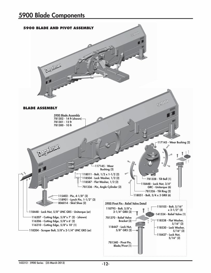
The 5900 Dozer Blade consists of a dozer blade connected to a pivot/main frame assembly.
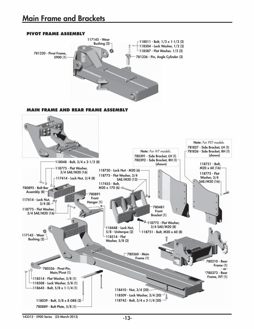
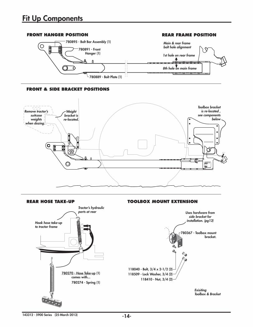
Typically, this assembly mounts to a front hanger bracket along with side or rear axle brackets that are bolted securely onto the frame of your tractor.
The blade is attachable/detachable with a simple D-lock mounting system and hydraulic hook-up.
The 5900 Blade has three hydraulically controlled ranges of motion – lift, angle & tilt.
Lift Angle Tilt
WELCOME PROOF OF OWNERSHIP
ABOUT THIS MANUAL
DESCRIPTION
Introduction
LeftSide
RightSide
Serial Number Plate
-2-143312 - 5900 Series (25-March-2013)
Safety
Why is SAFETY important to YOU?
3 BIG Reasons:
• Accidents Can Disable and Kill •AccidentsAreCostly •AccidentsCanBeAvoided
. . . for your own safety and that of others!
- If you are not familiar with basic agriculture & industrial safety, you must get training.
- Owners of equipment must give operating instructions to other operators such as family members or a hired hand.
- Making any design changes to equipment could cause a hazard, damage your machine & void your warranty.
YOU are responsible for the SAFE operation and maintenance of your Degelman implement. YOU must ensure that you and anyone else who is going to operate, maintain, or work around the machine be familiar with the operating and maintenance procedures, and related SAFETY information contained in this manual. This manual will take you step-by-step through your working day and will alert you to good safety practices that should be adhered to while operat ing this equipment.
Remember, YOU are the key to safety. Good safety practices not only protect you, but also the people around you. Make these practices a working part of your safety program. Be certain that EVERYONE operating this equipment is familiar with the recommended operating and maintenance procedures and follows all the safety precautions. Most accidents can be prevented. Do not risk injury or death by ignoring good safety practices.
•Ownersmustgiveoperatinginstructionstooperators or employees before allowing them to operate the unit, and at least annually thereafter per OSHA regulation 1928.57.
•Themostimportantsafetydeviceonthisequipment is a SAFE operator. It is the operator’s responsibility to read and understand ALL Safety and Operating instructions in the manual and to follow these. All accidents can be avoided!
•ApersonwhohasnotreadandunderstoodALLoperating and safety instructions is not qualified to operate the machine. An untrained operator exposes himself and bystanders to possible serious injury or death.
•Donotmodifytheequipmentinanyway.Unauthorized modifica tion may impair the function and/or safety and could affect the life of the equipment.
DANGER: Indicates an imminently hazardous situation that, if not avoided, WILL result in death or serious injury if proper precautions are not taken.
WARNING: Indicates a potentially hazardous situation that, if not avoided, COULD result in death or serious injury if proper precautions are not taken.
CAUTION: Indicates a potentially hazardous situation that, if not avoided, MAY result in minor or moderate injury if proper practices are not taken, or, serves as a reminder to follow appropriate safety practices.
Note the use of the Signal Words: DANGER, WARNING, and CAUTION with the safety messages. The appropriate Signal Word has been selected using the following guidelines:
SIGNAL WORDS
The Safety Alert Symbol identifies important safety messages applied to the dozer blade and in this manual. When you see this symbol, be alert to the possibility of injury or death. Follow the instructions provided on the safety messages.
The Safety Alert Symbol means:
ATTENTION! BECOME ALERT!
YOUR SAFETY IS INVOLVED!
SAFETY ALERT SYMBOL
YOU are RESPONSIBLE
-3-143312 - 5900 Series (25-March-2013)
WearProtectiveEquipment Note: Before working on machine, always turn
tractor off, set controls in neutral, and remove ignition key.
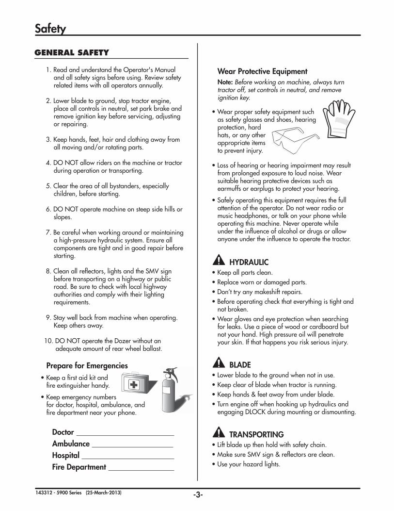
• Wear proper safety equipment such as safety glasses and shoes, hearing protection, hard hats, or any other appropriate items to prevent injury.
• Loss of hearing or hearing impairment may result from prolonged exposure to loud noise. Wear
suitable hearing protective devices such as earmuffs or earplugs to protect your hearing.
•Safelyoperatingthis equipment requires the full attention of the operator. Do not wear radio or music headphones, or talk on your phone while operating this machine. Never operate while under the influence of alcohol or drugs or allow anyone under the influence to operate the tractor.
Doctor Ambulance Hospital Fire Department
Prepare for Emergencies•Keepafirstaid kit and
fire extinguisher handy.
•Keep emergency numbers for doctor, hospital, ambulance, and fire department near your phone.
HYDRAULIC•Keep all parts clean. •Replace worn or damaged parts.•Don’t try any makeshift repairs. •Before operating check that everything is tight and
not broken.•Wear gloves and eye protection when searching
for leaks. Use a piece of wood or cardboard but not your hand. High pressure oil will penetrate your skin. If that happens you risk serious injury.
BLADE•Lower blade to the ground when not in use. •Keep clear of blade when tractor is running. •Keep hands & feet away from under blade. •Turn engine off when hooking up hydraulics and
engaging DLOCK during mounting or dismounting.
TRANSPORTING•Lift blade up then hold with safety chain.•Make sure SMV sign & reflectors are clean.•Use your hazard lights.
GENERAL SAFETY
1. Read and understand the Operator's Manual and all safety signs before using. Review safety related items with all operators annually.
2. Lower blade to ground, stop tractor engine, place all controls in neutral, set park brake and remove ignition key before servicing, adjusting or repairing.
3. Keep hands, feet, hair and clothing away from all moving and/or rotating parts.
4. DO NOT allow riders on the machine or tractor during operation or transporting.
5. Clear the area of all bystanders, especially children, before starting.
6. DO NOT operate machine on steep side hills or slopes.
7. Be careful when working around or maintaining a high-pressure hydraulic system. Ensure all components are tight and in good repair before starting.
8. Clean all reflectors, lights and the SMV sign before transporting on a highway or public road. Be sure to check with local highway authorities and comply with their lighting requirements.
9. Stay well back from machine when operating. Keep others away.
10. DO NOT operate the Dozer without an adequate amount of rear wheel ballast.
Safety
-4-143312 - 5900 Series (25-March-2013)
Operation
TO THE NEW OPERATOR OR OWNER
The Degelman Dozer Blade is a push type tractor attachment designed primarily for excavating, levelling and filling of dirt, snow and silage.
It is the owners or operators responsibility to read this manual carefully to learn how to operate the machine safely and how to set it to provide maximum efficiency. Safety is everyone’s business. By following safe operating practices, a safe environment is provided for the operator and bystanders.
The manual will take you step-by-step through your working day. By following the operating instructions in conjunction with a good maintenance program your machine will provide many years of trouble-free service.
BREAK-IN
Although there are no operational restrictions on the Dozer Blade when it is new, there are some mechanical checks that must be done to ensure the long term integrity of the unit. When using the machine for the first time, follow this procedure:
A. Before using:
1. Read Operator's Manual.
2. Lubricate all points shown in the Maintenance Section.
3. Check all bolt tightness.
B. After operating for 2 hours:
1. Check all hardware.
2. Check all hardware tightness.
3. Check all hydraulic system connections. Tighten if any are leaking.
C. After operating 10 hours:
1. Repeat Step B.
2. Go to the service schedule as outlined in the Maintenance Section.
TRACTOR PREPARATION
1. Wheel Spacing
Important: To avoid possible damage from over stressing tractor axles, use no tire combination which results in overall width greater than the width of the angle blade.
Important: Before beginning operation, turn the wheel fully to the right and left to be sure there is sufficient clearance between the tires and the angling cylinders. If necessary, move the wheels to a wider setting to provide clearance. See your Tractor Operator's Manual.
2. Rear Wheel Weight and Tire Inflation:
Add necessary rear end weights for efficient operation and safety. Any of the cast-iron weights recommended for your tractor or liquid in the tires, may be used for necessary ballast. Be sure the weight is distributed equally on each rear wheel.
Inflate front and rear tires to proper pressure as recommended in the Tractor Operator’s Manual for heavy front-mounted implements.
3. Checking HydraulicOilLevel:
Check the oil level in the tractor hydraulic system daily. Refer to your tractor operator's Manual for Instructions. Keep the oil supply up to the proper level. Before checking oil supply, fully extend and retract angle and lift cylinders 3 - 4 times and return the blade to the ground.
PRINCIPLES OF OPERATION
The dozer blade consists of a blade/cutting edge unit attached to a pivot-main frame combination suspended from the tractor by the front hanger and side or axle brackets. By driving the tractor forward with the blade either straight ahead or angled, and allowing the cutting edge to run just under the ground surface - dirt, silage or snow is relocated as desired.
ATTACHING THE DOZER BLADE
NOTE: Please refer to the assembly section of this manual - for full instructions for attaching your specific tractor and blade model.
BLEEDING THE HYDRAULICS
Before beginning operation, bleed the hydraulic system to remove any air. To do this, cycle the hydraulics several times by holding the cylinder fully extended for several seconds. This will cause any trapped air to be purged from cylinder.
COLD WEATHER OPERATION
To assure smooth operation in cold weather, cycle the cylinders several times to warm the oil in the hydraulic system.
-5-143312 - 5900 Series (25-March-2013)
Operation
ANGLING DOZER BLADE
The dozer blade can be hydraulically angled approximately 18° to the right or left by operating the proper tractor remote cylinder lever. In the angled position, the dozer blade can be used for backfilling trenches, side-casting into ditches, levelling and grading.
A dual relief valve is incorporated to protect the hydraulic angling system when the blade is overloaded. (This valve will bypass the hydraulic fluid and diminish the degrees that the blade was initially angled.)
Important: To avoid damage to tractor or blade, the hydraulic system must be hooked up properly including line to hydraulic tank drain.
FLOATING THE DOZER BLADE
Here are some the things you can do with your hydraulic system in float position:
By placing the remote cylinder operating lever for the lift function in float position, the blade may be used to smooth an area by running the tractor in reverse (refer to Tractor Operator's Manual). On moderate grades, the tractor can be driven up the slope and the blade dropped down for back-dragging. It may also be used to push dirt or snow on pavement or other smooth surfaces.
OPERATOR’S RESPONSIBILITY
Every operator should read this manual and be instructed in safe operating procedures. An untrained operator is not qualified to operate this machine and could place themselves or bystanders in danger.
OPERATING SPEED
For normal operation, operate the tractor at a comfortable or manufacturer recommended speed. When operating over rough terrain or limited to space, reduce engine speed. The actual forward speed will be determined by tractor horsepower, land density and depth of cut.
Experience will teach you the most efficient operating speed, but as a rule 3-4 MPH (5-7 km/h) is a normal operating range.
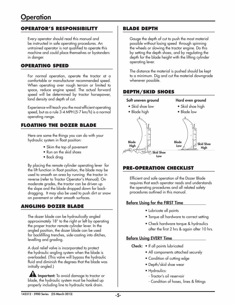
DEPTH/SKID SHOES
Softunevenground
• Skid shoe low• Blade high
Hardevenground
• Skid shoe high• Blade low
Skid ShoeHigh
Skid ShoeLow
BladeLow
BladeHigh
BLADE DEPTH
Gauge the depth of cut to push the most material possible without losing speed through spinning the wheels or slowing the tractor engine. Do this by setting the depth shoes, and by regulating the depth for the blade height with the lifting cylinder operating lever.
The distance the material is pushed should be kept to a minimum. Dig and cut the material downgrade whenever possible.
PRE-OPERATION CHECKLIST
Efficient and safe operation of the Dozer Blade requires that each operator reads and understands the operating procedures and all related safety procedures outlined in this manual.
Before Using for the FIRST Time
•Lubricateallpoints
•Torqueallhardwaretocorrectsetting
•Check hardware torque & hydraulics after the first 2 hrs & again after 10 hrs.
Follow this procedure when preparing to transport:
1. Clear the area of bystanders, especially small children, before converting into transport configuration.
2. Operate the lift hydraulics to raise the blade fully and install a certified safety chain to secure it.
3. Clean the SMV sign, lights and reflectors.
4. Maintain a safe speed. Slow down when cornering and on rough roads.
5. Slow down and pull off to the side of the road when meeting other traffic.
6. Use hazard flashers on tractor unless prohibited by law.
Transport & Storage
TRANSPORT SAFETY
• Read and understand ALL the information in the Operator's Manual regarding procedures and SAFETY when operating the machine in the field/yard or on the road.
• Check with local authorities regarding machine transport on public roads. Obey all applicable laws and regulations.
• Always travel at a safe speed. Use caution when making corners or meeting traffic.
• Make sure the SMV (Slow Moving Vehicle) emblem and all the lights and reflectors that are required by the local highway and transport authorities are in place, are clean and can be seen clearly by all overtaking and oncoming traffic.
• Keep to the right and yield the right-of-way to allow faster traffic to pass. Drive on the shoulder, if permitted by law.
• Always use hazard warning flashers on tractor when transporting, unless prohibited by law.
STORAGE
After the season's use, completely inspect all major systems of the machine. Repair or replace any worn or damaged components to prevent unnecessary down time at the beginning of next season.
Since the unit can be used in extremely adverse conditions during the season, the machine should be carefully prepared for storage to ensure that all dirt, mud, debris and moisture has been removed.
Follow this procedure when preparing to store:
1. Wash the entire machine thoroughly using a water hose or pressure washer to remove all dirt, mud, debris or residue.
2. Inspect all parts to see if anything has become entangled in them. Remove the entangled material.
3. Lubricate all grease fittings to remove any moisture.
4. Inspect all hydraulic hoses, fittings, lines and couplers. Tighten any loose fittings. Replace any hose that is badly cut, nicked or abraded or is separating from the crimped end of the fitting.
5. Touch up all paint nicks and scratches to prevent rusting.
6. Oil the exposed rams on the hydraulic cylinder to prevent rusting.
7. Select an area that is dry, level and free of debris.
STORAGE SAFETY
• Store unit in an area away from human activity.
• Do not permit children to play near the stored unit.
-7-143312 - 5900 Series (25-March-2013)
Troubleshooting
Dozer Falls Down In Transport.
Lift cylinder hydraulic circuit not connected correctly.
Trace your hoses from front to back of tractor, making sure angle circuitconnectedtorearreliefvalve,notliftcircuit.
D-lock will not stay in open position, falls closed.
Clip pin not being used. Use clip pin to hold open.
Dozer not following ground contour.
Tilt circuit not allowed to float. Float hydraulic tilt circuit.
-8-143312 - 5900 Series (25-March-2013)
Maintenance
LUBRICANTS
1. Grease: Use an SAE multi-purpose grease with extreme pressure (EP) performance. Also acceptable is an SAE multi-purpose lithium base grease.
2. Storing Lubricants: Your machine can operate at top efficiency only if clean lubricants are used. Use clean containers to handle all lubricants. Store them in an area protected from dust, moisture and other contaminants.
GREASING
1. Use only a hand-held grease gun for all greasing.
2. Wipe grease fitting with a clean cloth before greasing, to avoid injecting dirt.
3. Replace and repair broken fittings immediately.
4. If fittings will not take grease, remove and clean thoroughly. Also clean lubricant passageway. Replace fitting if necessary.
5. Inject grease until you see grease being expelled from the pin or bushing areas.
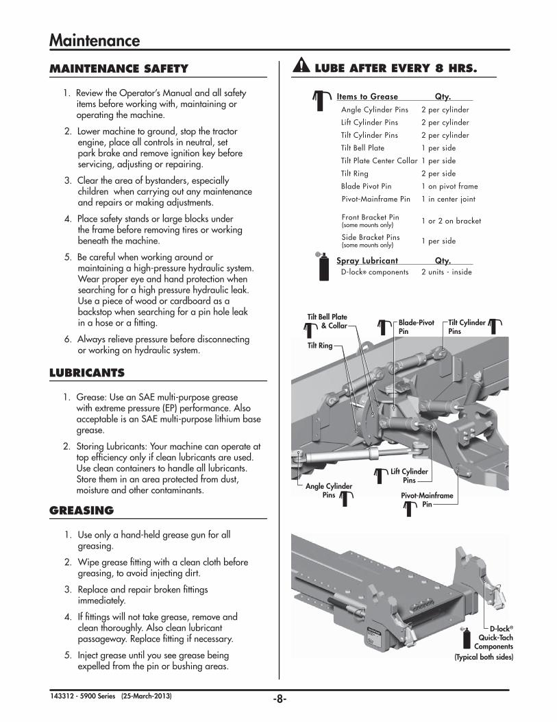
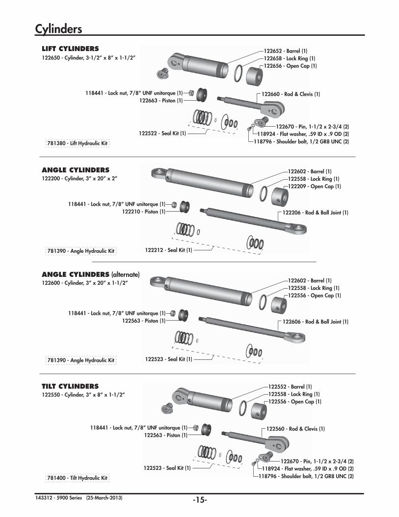
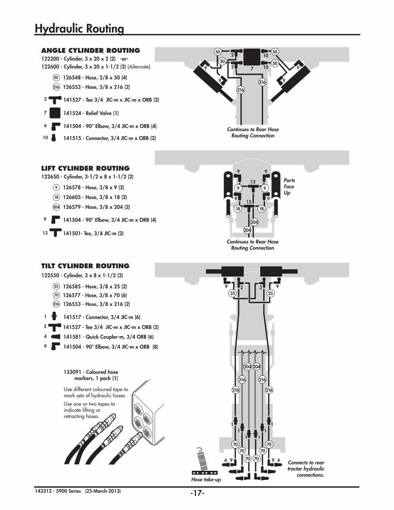
Items to Grease Qty. Angle Cylinder Pins 2 per cylinder
Lift Cylinder Pins 2 per cylinder
Tilt Cylinder Pins 2 per cylinder
Tilt Bell Plate 1 per side
Tilt Plate Center Collar 1 per side
Tilt Ring 2 per side
Blade Pivot Pin 1 on pivot frame
Pivot-Mainframe Pin 1 in center joint
Front Bracket Pin 1 or 2 on bracket(some mounts only)
Side Bracket Pins 1 per side(some mounts only)
Spray Lubricant Qty. D-lock® components 2 units - inside
LUBE AFTER EVERY 8 HRS.MAINTENANCE SAFETY
1. Review the Operator’s Manual and all safety items before working with, maintaining or operating the machine.
2. Lower machine to ground, stop the tractor engine, place all controls in neutral, set park brake and remove ignition key before servicing, adjusting or repairing.
3. Clear the area of bystanders, especially children when carrying out any maintenance and repairs or making adjustments.
4. Place safety stands or large blocks under the frame before removing tires or working beneath the machine.
5. Be careful when working around or maintaining a high-pressure hydraulic system. Wear proper eye and hand protection when searching for a high pressure hydraulic leak. Use a piece of wood or cardboard as a backstop when searching for a pin hole leak in a hose or a fitting.
6. Always relieve pressure before disconnecting or working on hydraulic system.
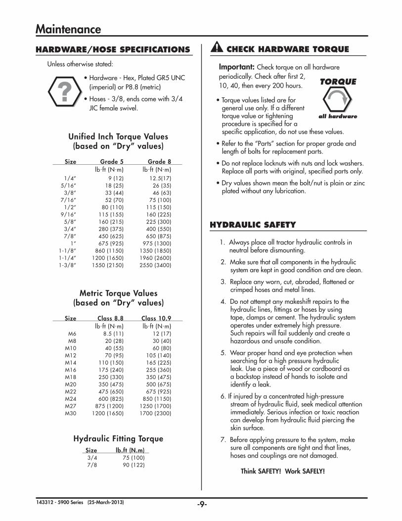
Important: Check torque on all hardware periodically. Check after first 2, 10, 40, then every 200 hours.
• Torque values listed are for general use only. If a different torque value or tightening procedure is specified for a specific application, do not use these values.
•Refer to the “Parts” section for proper grade and length of bolts for replacement parts.
•Do not replace locknuts with nuts and lock washers. Replace all parts with original, specified parts only.
•Dry values shown mean the bolt/nut is plain or zinc plated without any lubrication.
1. Always place all tractor hydraulic controls in neutral before dismounting.
2. Make sure that all components in the hydraulic system are kept in good condition and are clean.
3. Replace any worn, cut, abraded, flattened or crimped hoses and metal lines.
4. Do not attempt any makeshift repairs to the hydraulic lines, fittings or hoses by using tape, clamps or cement. The hydraulic system operates under extremely high pressure. Such repairs will fail suddenly and create a hazardous and unsafe condition.
5. Wear proper hand and eye protection when searching for a high pressure hydraulic leak. Use a piece of wood or cardboard as a backstop instead of hands to isolate and identify a leak.
6. If injured by a concentrated high-pressure stream of hydraulic fluid, seek medical attention immediately. Serious infection or toxic reaction can develop from hydraulic fluid piercing the skin surface.
7. Before applying pressure to the system, make sure all components are tight and that lines, hoses and couplings are not damaged.
Think SAFETY! Work SAFELY!
CHECK HARDWARE TORQUE
TORQUE
all hardware
-10-143312 - 5900 Series (25-March-2013)
SAFETY DECALS
1. Keep safety decals and signs clean and legible at all times.
2. Replace safety decals and signs that are missing or have become illegible.
3. Replaced parts that displayed a safety sign should also display the current sign.
4. Safety decals or signs are available from your Dealer Parts Department. Safety decals will be available upon request.
How to Install Safety Decals:
• Be sure that the installation area is clean and dry.
• Decide on the exact position before you remove the backing paper.
• Remove the smallest portion of the split backing paper.
• Align the decal over the specified area and carefully press the small portion with the exposed sticky backing in place.
• Slowly peel back the remaining paper and carefully smooth the remaining portion of the decal in place.
REPLACEMENT DECALS
Decals, especially safety and reflective, should be replaced when they become damaged or worn. Contact your dealer.
Note:Toavoidequipmentdamage,Tilt kit must also be purchased and installed if using the Angle Lockout kit.
781618 - Angle Lock-Out Assy, Outside (2)
781623 - Angle Lock-Out Assy, Inside (2)
Angle Lockout Kit Installation:1 - Install components loosely.2 - Ensure blade is straight.3 - Measure and mark positions for welding.4 - Tack weld into place (if desired).5 - Remove and weld fully.6 - Clean and paint.7 - Reinstall into place.
3. Drive forward until the front bracket pin is just behind the front hanger’s hook. It should be lined up so you can drive into the front hanger when it is raised up.
4. Hook up the hydraulics.
5. Extend the lift cylinders until the pin and hook are level.
6. Drive forward until the pin is in the front hanger.
7. Close the lift cylinder bringing the D-lock connection points up to the side bracket pins. (By closing the lift cylinder, the weight of the front of the blade swings the back frame upward, engaging the side bracket pins.)
8. Close the D-lock connections using the handle.
9. Install the D-lock clip pins and store the handle.
10. Note: There should be a 3/8” to 5/8” gap between the front bracket pin and the front hanger hook.
Important: You must close lift cylinder & lift blade before unlatching D-lock! This transfers the weight to the front hooks and frees up the D-lock. Otherwise, the whole assembly may come crashing down.
Proceduretoremoveblade:
1. Close lift cylinder to lift blade.
2. Open D-lock latches.
3. Lower blade by extending the lift cylinders - rear frame will disengage from brackets.
4. Check that connection points are disconnected and clear to back out.
5. Unhook hydraulics.
6. Back tractor out.
DANGER
UNHOOKING - REMOVING BLADE
103/8” - 5/8” gap
Front Bracket Pin
Hook
5Level
6
12
Lift Cylinder
D-lock
Pivot Frame
Front Bracket Pin
Side Bracket Pin
Rear / Main Frame
Hook
3
4
7
Side Bracket Pin
89
Mounting 10STEPSTEP
Important: There should be a gap (3/8” or larger) between the inside of the hook to the front of the bracket pin. The amount of gap may vary between specific models, but having a gap at this location is important.
Please note: The brackets and frame assembly for your particular fit-up may differ significantly from those used in the diagram, however, the procedure steps remain the same.
-20-143312 - 5900 Series (25-March-2013)
2 YearLimited Warranty
Degelman Industries Ltd. (“Degelman”) warrants to the original purchaser of any new Degelman equipment, purchased from an authorized Degelman dealer, that the equipment will be free from defects in material and workmanship for a period of two (2) years from the date of delivery, for non-commercial use (including farm, institutional, government, and municipality) and (1) year from the date of delivery for commercial use. The obligation of Degelman to the purchaser under this warranty is limited to the repair or replacement of defective parts in the first year and to the provision, but not the installation of replacement parts in the second year. Degelman reserves the right to inspect any equipment or parts which are claimed to have been defective in material or workmanship.
This warranty limits its replacement or repair coverage to what is consistent with the warranty of Degelman’s suppliers ofpurchased components. Replacement or repair parts installed in the equipment covered by this limited warranty are warranted for ninety (90) days from the date of delivery of such part or the expiration of the applicable new equipment warranty period, which ever occurs later. Warranted parts shall be provided at no cost to the user at an authorized Degelman dealer during regular working hours. Warranted replacement parts will either be replaced or rebuilt at Degelman’s discretion.
This warranty shall not be interpreted to render Degelman Industries Ltd. liable for injury, death, property damage or damages of any kind, whether direct, consequential, or contingent to property. Without limiting the generality of the foregoing, Degelman shall not be liable for damages resulting from any cause beyond its reasonable control, including, without limitation, loss of crops, any expense or loss of labour, supplies, rental machinery or loss of use.
No other warranty of any kind whatsoever, express or implied is made with respect to this sale; and all implied warranties of merchantability and fitness for a particular purpose which exceed the obligations set forth in this written warranty are hereby disclaimed and excluded from this sale. This exclusion shall not apply in any jurisdiction where it is not permitted by law.
This limited warranty shall not apply:
1. If, in the sole opinion of Degelman, the unit has been subjected to misapplication, abuse, misuse, negligence, accident or incorrect installation.
2. To any goods that have sustained damage or deterioration attributable to a lack of routine maintenance (eg. Re-torque of mounting hardware.)
3. If parts not made or supplied by Degelman have been used in the connection with the unit, if, in the sole judgement of Degelman such use affects its performance, safety, stability or reliability.
4. If the unit has been altered or repaired outside of an authorized Degelman dealership in a manner which, in the sole judgement of Degelman, affects its performance, safety, stability or reliability.
5. To expendable or wear items such as cutting edges, skid shoes, and any other items that in the company’s sole judgement is a wear item.
No employee or representative of Degelman Industries Ltd. is authorized to change this limited warranty in any way or grant any other warranty unless such change is made in writing and signed by the Degelman Service Manager.
This limited warranty is subject to any future availability of supply, which may directly affect Degelman’s ability to obtain materials or manufacture replacement parts.
Degelman reserves the right to make improvements in design or changes in specifications at any time, without incurring obligations to owners of equipment previously delivered.
This limited warranty is subject to compliance by the customer to the enclosed Retail Customer’s Responsibility Under Degelman Warranty.
Make certain the warranty registration card has been forwarded to: Degelman Industries Ltd. Box 830 272 Industrial Dr. Regina, SK, Canada S4P 3B1