Part No. 350245 Form No. F021302A Page 1 of 12 Thank You for Selecting Operator Owner's Manual The Powerful CR POWER RAKE Specifications FLAIL BLADES P/N 350251. A complete replacement set. 52 of our high quality flail blades for your CR. Includes 8 new lock clips for replacement installa- tion. CR550, CR550H FLAIL SHAFTS P/N 350185. A full set of four shafts for replacement. Includes 8 new lock clips for replace- ment installation. Note: We recommend replacing the shafts when you replace flails. REPLACEMENT PARTS DRIVE BELT P/N 350207. Original Equipment drive belt for your CR. SLICING REEL P/N 350252. A complete verti-slicing reel for your CR. 20" wide reel for use in grasses that require vertical cutting, and for assisting in lawn overseeding projects. ACCESSORIES SLICING BLADES P/N 350187. A full set of twenty blades for replacement. Includes 40 new capscrews, and lock nuts for replacement installation. R 2 1 3 CR550 CR550H ENGINE: H.P. 5.5 (4.1 kW) 5.5 (4.1 kW) ENGINE: TYPE B&S OHV HONDA OHV ENGINE: FUEL CAP. 3.0 qt. (2.84 L) 3.88 qt. (3.41 L) ENGINE: OIL CAP. 0.66 qt. (0.62 L) 0.69 qt. (0.65 L) WEIGHT: UNIT 125# (56.8 kg) 129# (58.6 kg) WEIGHT: SHIPPING 140# (63.6 kg) 144# (65.4 kg) ENGINE WEIGHT: 30# (13.6 kg) 34# (15.4 kg) MAX. ENGINE OPERATING SLOPE 15° 20° SPACER BUMPERS P/N 350258. A complete replacement set. 44 of 1/2" spacer bumpers and 4 of 1/4" spacer bumpers
Transcript
Part No. 350245 Form No. F021302APage 1 of 12
T h a n k Yo u f o r S e l e c t i n g
Operator Owner's Manual
The Powerful CR POWER RAKE
Specifications
FLAIL BLADESP/N 350251. A complete replacementset. 52 of our high qualityflail blades for your CR.Includes 8 new lock clipsfor replacement installa-tion.
CR550, CR550H
FLAIL SHAFTSP/N 350185. A full set of four shafts forreplacement. Includes 8new lock clips for replace-ment installation.Note: We recommendreplacing the shafts whenyou replace flails.
REPLACEMENT PARTS
DRIVE BELTP/N 350207.Original Equipment drivebelt for your CR.
SLICING REELP/N 350252.A complete verti-slicingreel for your CR. 20" widereel for use in grassesthat require verticalcutting, and for assistingin lawn overseedingprojects.
ACCESSORIES
SLICING BLADESP/N 350187. A full set of twenty bladesfor replacement. Includes40 new capscrews, andlock nuts for replacementinstallation.
SPACER BUMPERSP/N 350258.A complete replacementset. 44 of 1/2" spacerbumpers and 4 of 1/4"spacer bumpers
Part No. 350245 Form No. F021302APage 2 of 12
IN THE INTEREST OF SAFETY
THIS SYMBOL MEANS WARNING OR CAUTION. DEATH, PERSONAL INJURY AND/OR PROPERTYDAMAGE MAY OCCUR UNLESS INSTRUCTIONS ARE FOLLOWED CAREFULLY.
BEFORE STARTING ENGINE, READ AND UNDERSTAND THE “ENTIRE OPERATOR'S MANUAL &ENGINE MANUAL.”
WARNING: DO NOT1. DO NOT run engine in an enclosed area.Exhaust gases contain carbon monoxide, anodorless and deadly poison.
2. DO NOT place hands or feet near movingor rotating parts.
3. DO NOT store, spill or use gasoline nearan open flame, or devices such as a stove,furnace, or water heater which use a pilotlight or devices which can create a spark.
4. DO NOT refuel indoors where area is notwell ventilated. Outdoor refueling is recom-mended.
5. DO NOT fill fuel tank while engine isrunning. Allow engine to cool for 2 minutesbefore refueling. Store fuel in approvedsafety containers.
6. DO NOT remove fuel tank cap whileengine is running.
7. DO NOT operate engine when smell ofgasoline is present or other explosiveconditions exist.
8. DO NOT operate engine if gasoline isspilled. Move machine away from the spilland avoid creating any ignition until thegasoline has evaporated.
9. DO NOT transport unit with fuel in tank.
10. DO NOT smoke when filling fuel tank.
11. DO NOT choke carburetor to stopengine. Whenever possible, graduallyreduce engine speed before stopping.
12. DO NOT run engine at excessivespeeds. This may result in injury & /ordamage to unit.
13. DO NOT tamper with governor springs,governor links or other parts which maychange the governed engine speed.
14. DO NOT tamper with the engine speedselected by the engine manufacturer.
15. DO NOT check for spark with spark plugor spark plug wire removed. Use anapproved tester.
16. DO NOT crank engine with spark plugremoved. If engine is flooded, place throttlein “FAST” position and crank until enginestarts.
17. DO NOT strike flywheel with a hardobject or metal tool as this may causeflywheel to shatter in operation. Use propertools to service engine.
18. DO NOT operate engine without amuffler. Inspect periodically and replace, ifnecessary. If engine is equipped withmuffler deflector, inspect periodically andreplace, if necessary, with correct deflector.
19. DO NOT operate engine with anaccumulation of grass, leaves, dirt or othercombustible material in the muffler area.
20. DO NOT use this engine on any forestcovered, brush covered, or grass coveredunimproved land unless a spark arrester isinstalled on the muffler. The arrester mustbe maintained in effective working order bythe operator. In the State of California theabove is required by law (Section 4442 ofthe California Public Resources Code).Other states may have similar laws. Federallaws apply on federal lands.
21. DO NOT touch hot muffler, cylinder, orfins because contact may cause burns.
22. DO NOT run engine without air cleaneror air cleaner cover.
23. DO NOT operate during excessivevibration!24. DO NOT leave machine unattendedwhile in operation.
25. DO NOT park machine on a steep gradeor slope.
WARNING: DO1. ALWAYS DO remove the wire from thespark plug when servicing the engine orequipment TO PREVENT ACCIDENTALSTARTING.
2. DO keep cylinder fins and governorparts free of grass and other debriswhich can affect engine speed.
3. DO pull starter cord slowly until resis-tance is felt. Then pull cord rapidly to avoidkickback and prevent hand or arm injury.
4. DO examine muffler periodically to besure it is functioning effectively. A worn orleaking muffler should be repaired orreplaced as necessary.
5. DO use fresh gasoline. Stale fuel cangum carburetor and cause leakage.
6. DO check fuel lines and fittings frequentlyfor cracks or leaks. Replace if necessary
8. Inspect machine and work area beforestarting unit.
VIBRATIONVIBRATION LEVELS 3.2 g max.
Vibration levels at the operators handles weremeasured in the vertical, lateral, and longitudinaldirections using calibrated vibration test equipment.Tests were performed on 09/08/97 under theconditions listed:
WIND DIRECTION:
HUMIDITY:
TEMPERATURE:
BAROMETRIC PRESSURE:
SOUND
Sound tests conducted were in accordance with 2000/14/EECand were performed on 2/9/2002 under the conditions listed:
WARNING: The Engine Exhaust from this product contains chemicals known
to the State of California to cause cancer, birth defects or other reproductive harm.
○ ○ ○ ○ ○ ○ ○ ○
WIND SPEED:
NOTE: Sound power level listed is the highest value for any model in thismanual. Please refer to serial plate on the unit for the sound power levelfor your model.
99 dBWIND DIRECTION:
HUMIDITY:
TEMPERATURE:
BAROMETRIC PRESSURE:
GENERAL CONDITION:
29.91" Hg (760mm Hg)
31 %
East
10 MPH (16.1 kmh)
85° F (29.4° C)
Sunny
WIND SPEED:
Part No. 350245 Form No. F021302APage 3 of 12
PUT OIL IN ENGINE BEFORE STARTING
Read all safety and operating instructionsbefore assembling or starting this unit.
EngineManual Per
Model
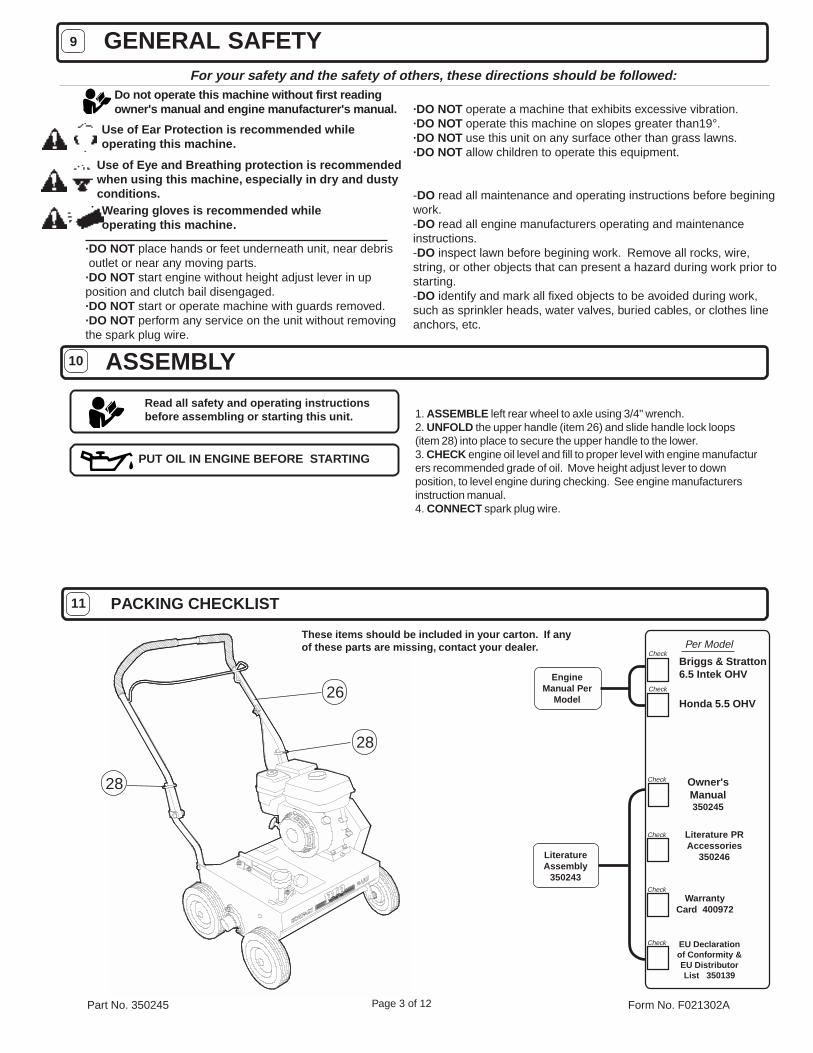
These items should be included in your carton. If anyof these parts are missing, contact your dealer.
ASSEMBLY
PACKING CHECKLIST
GENERAL SAFETYFor your safety and the safety of others, these directions should be followed:
Use of Ear Protection is recommended whileoperating this machine.
Use of Eye and Breathing protection is recommendedwhen using this machine, especially in dry and dustyconditions.
·DO NOT place hands or feet underneath unit, near debris outlet or near any moving parts.·DO NOT start engine without height adjust lever in upposition and clutch bail disengaged.·DO NOT start or operate machine with guards removed.·DO NOT perform any service on the unit without removingthe spark plug wire.
·DO NOT operate a machine that exhibits excessive vibration.·DO NOT operate this machine on slopes greater than19°.·DO NOT use this unit on any surface other than grass lawns.·DO NOT allow children to operate this equipment.
-DO read all maintenance and operating instructions before beginingwork.-DO read all engine manufacturers operating and maintenanceinstructions.-DO inspect lawn before begining work. Remove all rocks, wire,string, or other objects that can present a hazard during work prior tostarting.-DO identify and mark all fixed objects to be avoided during work,such as sprinkler heads, water valves, buried cables, or clothes lineanchors, etc.
9
10
11
Do not operate this machine without first readingowner's manual and engine manufacturer's manual.
Check
Check
Briggs & Stratton6.5 Intek OHV
Per Model
Honda 5.5 OHV
1. ASSEMBLE left rear wheel to axle using 3/4" wrench.2. UNFOLD the upper handle (item 26) and slide handle lock loops(item 28) into place to secure the upper handle to the lower.3. CHECK engine oil level and fill to proper level with engine manufacturers recommended grade of oil. Move height adjust lever to downposition, to level engine during checking. See engine manufacturersinstruction manual.4. CONNECT spark plug wire.
LiteratureAssembly
350243
Wearing gloves is recommended whileoperating this machine.
Check Owner'sManual350245
Literature PRAccessories
350246
Check
Check EU Declarationof Conformity &EU DistributorList 350139
CheckWarranty
Card 400972
28
28
26
Part No. 350245 Form No. F021302APage 4 of 12
These labels should be included on your Power Rake. If any ofthese labels are damaged, replace them before putting thisequipment into operation. Item and part numbers are given to helpin ordering replacement labels.
Label Do Not Fill WhileEngine Is HotItem 50 Part No.400268
EXPLOSIVE FUELSTOP ENGINE AND ALLOW TOCOOL BEFORE REFUELING.
4002
68
WARNING
1414141414
1515151515
INSTRUCTION LABELS
ENGINE LABELS
DANGER
8107
36
Label Danger Flying MaterialItem 48 Part No.810736
1313131313 CONTROLS
Set lever to choke position whenstarting a cold engine
Set lever to desired engine speed.Move lever completely to the leftto stop engine
READ OWNERS MANUALBEFORE OPERATING
BEFORE STARTING, MAKE SURE:
USE PERSONALPROTECTION EQUIPMENT
HEIGHT ADJUST LEVER IS IN DOWN POSITION.ALL GUARDS ARE ATTACHED.
USE ONLY A QUALIFIED MECHANIC TO SERVICE THIS MACHINE.
INSPECT MACHINE BEFORE EACH USE AND REPLACE ANY WORN AND DAMAGED PARTS.
CHECK ENGINE OIL DAILY.
PROPERLY SECURE EQUIPMENT BEFORE TRANSPORTING.DISCONNECT SPARK PLUG WIRE BEFORE SERVICING UNIT.
FOR PREVENTATIVE MAINTENANCE
INSPECT AND CLEAN ENGINE AIR FILTER DAILY. REPLACE AS NEEDED.GREASE REEL BEARINGS AND LUBRICATE DEPTH CONTROL LEVER EVERY ENGINE OIL CHANGE.
ALWAYS:
ROTATE KNOB TO ADJUST BLADE DEPTH
BLADES UPTRANSPORT POSITION
BLADES DOWNOPERATING POSITION
PROTECT BYSTANDERSFLYING DEBRIS
BLADES UP BLADES DOWN
3502
24
LOOSEN JAM NUT BEFORE ADJUSTING BLADE DEPTH THEN
TIGHTEN BACK TO LOCK IN PLACE
Label Instructions Height AdjustItem 35 Part No. 350224
WARNING
9003
27
Label Danger GuardItem 52 Part No.900327
Briggs & Stratton
'' '
..
Honda
OIL ALERT
ENGINE STOPS IMMEDIATELY.WHEN OIL LEVEL LOW,
PULL TO ENGAGE CLUTCHRELEASE TO DISENGAGE CLUTCH
8305
03
Label Clutch Item 49 Part No.830503
RUN CHOKE
STOP
B & S ENGINE THROTTLE CONTROLHONDA ENGINE THROTTLE CONTROL
THROTTLE LEVER
FUEL VALVE CHOKE LEVER
RUN CHOKEON
OFF
THIS ENGINE EQUIPPED WITH LOW OIL SENSOR, IF ENGINE WILLNOT START, CHECK OIL LEVEL
WARNINGRead and follow OperatingInstructions before running engine.
Gasoline is flammable. Allow engineto cool at least 2 minutes before fueling.
Engines emit carbon monoxide,DO NOT run in enclosed area.
Part No. 350245 Form No. F021302APage 5 of 12
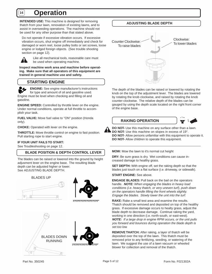
ENGINE: See engine manufacturer’s instructionsfor type and amount of oil and gasoline used.
Engine must be level when checking and filling oil andgasoline.
ENGINE SPEED: Controlled by throttle lever on the engine.Under normal conditions, operate at full throttle to accom-plish your task.
FUEL VALVE: Move fuel valve to "ON" position (Hondaonly).
CHOKE: Operated with lever on the engine.
THROTTLE: Move throttle control on engine to fast position.Pull starting rope to start engine.
IF YOUR UNIT FAILS TO START:See Troubleshooting on page 12.
INTENDED USE: This machine is designed for removingthatch from your lawn, renovation of existing lawns, and toassist in overseeding operations. The machine should notbe used for any other purpose than that stated above.
Inspect machine work area and machine before operat-ing. Make sure that all operators of this equipment aretrained in general machine use and safety.
Do not operate if excessive vibration occurs. If excessivevibration occurs, shut engine off immediately and check fordamaged or worn reel, loose pulley bolts or set screws, looseengine or lodged foreign objects. (See trouble shootingsection on page 12).
1616161616 Operation
STARTING ENGINE
RAKING OPERATION
Like all mechanical tools, reasonable care mustbe used when operating machine.
MOW: Mow the lawn to it's normal cut height
DRY: Be sure grass is dry. Wet conditions can cause in-creased damage to healthy grass.
SET DEPTH: With engine off, set the raking depth so that theblades just touch on a flat surface (i.e. driveway, or sidewalk).
START ENGINE: See above.
ENGAGE BLADES: Pull back on the bail on the operatorshandle. NOTE: When engaging the blades in heavy loadconditions (i.e. heavy thatch, or very uneven turf), push downon the operators handle lifting the front wheels slightly.Engage the blades. Slowly lower the unit into the turf.
RAKE: Rake a small test area and examine the results.Thatch should be removed and deposited on top of the healthygrass. If excessive damage occurs to healty grass, adjust theblade depth to decrease damage. Continue raking the yard,working in one direction (i.e. north-south, or east-west).NOTE: If a large drop in engine RPM occurs, or the unit pullsyou forward and bounces during operation the blade depth isset too low.
REMOVE THATCH: After raking, a layer of thatch will bedeposited over the top of the lawn. This thatch must beremoved prior to any fertilizing, seeding, or watering of thelawn. We suggest the use of a lawn vacuum or wheeledblower for collection and removal of the thatch.
DO NOT- Use this machine on any surface other than a lawn.DO NOT- Use this machine on slopes in excess of 19°.DO NOT- Allow persons unfamiliar with this equipment to operate it.DO NOT- Allow children to operate this equipment.
The blades can be raised or lowered into the ground by heightadjusment lever on the engine base. The resulting bladedepth can be adjusted higher or lower.See ADJUSTING BLADE DEPTH.
BLADE POSITION & DEPTH CONTROL LEVER
Clockwise:To lower bladesCounter Clockwise:
To raise blades
ADJUSTING BLADE DEPTH
The depth of the blades can be raised or lowered by rotating theknob on the top of the adjustment lever. The blades are loweredby rotating the knob clockwise, and raised by rotating the knobcounter-clockwise. The relative depth of the blades can begauged by using the depth scale located on the right front cornerof the engine base.
BLADES UPTRANSPORT
BLADES DOWNRUNNING
Part No. 350245 Form No. F021302APage 6 of 12
OPERATION continued1616161616
OVERSEEDING OPERATION continued
MOW: Mow the lawn to it's normal cut height
DRY: Be sure grass is dry. Wet conditions can cause in-creased damage to healty grass.
SET DEPTH: With engine off, set the raking depth so that theblades just touch on a flat surface (i.e. driveway, or sidewalk).
START ENGINE: See Page 5.
ENGAGE BLADES: Pull back on the bail on the operatorshandle. NOTE: When engaging the blades in heavy loadconditions (i.e. heavy thatch, or very uneven turf), push downon the operators handle lifting the front wheels slightly.Engage the blades. Slowly lower the unit into the turf.
SLICE: Verti-cut a small test area and examine the results.Some thatch and cut stems should be removed and depositedon top of the healthy grass. Grass runners should be cut andready for removal. If excessive damage occurs to healthygrass, adjust the blade depth to decrease damage. Continueraking the yard, working in one direction (i.e. north-south, oreast-west). NOTE: If a large drop in engine RPM occurs, orthe unit pulls you forward and bounces during operation theblade depth is set too low.
REMOVE THATCH/STEMS: After verti-cutting, a layer ofthatch and cut stems will be deposited over the top of the lawn.We suggest the use of a lawn vacuum or wheeled blower forcollection and removal of the thatch/stems.
DO NOT- Use this machine on any surface other than a lawn.DO NOT- Use this machine on slopes in excess of 19°.DO NOT- Allow persons unfamiliar with this equipment tooperate it.DO NOT- Allow children to operate this equipment.
RAKING/SLICING TIPS
THATCH: Thatch is a dense layer of dead grass, clippings,and roots that builds up over time at the base of of the lawnpreventing air, water, and fertilizer from reaching the soil.This can cause shallow root development and make a lawnmore susceptible to drought and disease. Thatch alsoprovides an ideal environment for insects to hide andmultiply. Periodic removal of thatch will keep your lawn ingood health.
HEAVY THATCH: Lawns with an excessive amount of thatchwill require multiple treatments for effective removal. Tryingto remove excessive thatch (greater than 3/4"[19 mm] deep)in one treatment will damage or destroy the living part of thelawn. It is best to remove heavy thatch in seasonal treat-ments (i.e. spring, and fall).
CHECK: Before begining, it is best to evaluate the condi-tion of the lawn by cutting one or more core samples fromarea to be treated. A core can be cut using a piece of pvc,or metal pipe. Hammer the pipe into the ground, remove it,push the core out of the pipe and inspect it to determine thedepth of thatch in your yard.
SLOPES: Rake slopes across not up and down. This ismuch easier and safer for the operator and is better for thelawn. Raking across will help to reduce runoff duringwatering and allow the sloped ground to hold more seed,fertilizer, and water. The units maximum operating slope is35% or 19°.
DEPTH: The wide range of depth adjusment on your unit isprovided to allow for blade wear. Setting the reel deeper willnot produce better, or quicker results. The flail reel isintended to be set so it just touches the surface on flatground. The slicing reel should be set even with the groundfor verti-slicing work, and set to a maximum 1/2" depth foroverseeding jobs. Setting the reel deeper than this will onlyresult in premature wear on the unit (i.e. failed belt). If youdesire to work the ground deeper than the above guidlinesallow, it should be done gradually in multiple passes.
Hints!
OVERSEEDING OPERATION
MOW: Mow the lawn to it's normal cut height
DRY: Be sure grass is dry. Wet conditions can cause in-creased damage to healthy grass.
SEED: Spred grass seed according to the seed suppliersdirections (e.g. 10 lbs. per 1000 ft2 [4.5 kg. per 93 m2 ])
SET DEPTH: With engine off, set the raking depth so that theblades reach 1/4"-1/2"(6-12 mm) below a flat surface (i.e.driveway, or sidewalk).
START ENGINE: See Page 5.
ENGAGE CLUTCH: Pull back on the bail on the operatorshandle. NOTE: When engaging the clutch in heavy loadconditions (i.e. heavy thatch, or very uneven turf), push downon the operators handle lifting the front wheels slightly.Engage the clutch. Slowly lower the unit into the turf.
DO NOT- Use this machine on any surface other than a lawn.DO NOT- Use this machine on slopes in excess of 19°.DO NOT- Allow persons unfamiliar with this equipment tooperate it.DO NOT- Allow children to operate this equipment.
SLICE: Run machine over the area that has been seeded toincorporate the seed into the soil. If excessive damageoccurs to healthy grass, adjust the blade depth to decreasedamage. Continue raking the yard, working in one direction(i.e. north-south, or east-west). NOTE: If a large drop inengine RPM occurs, or the unit pulls you forward andbounces during operation the blade depth is set too low.
WATER/FERTILIZE: After the seed has been worked intothe soil, water and fertilize according to the seed suppliersdirections.
VERTI-CUTTING OPERATION
This unit is equipped with a folding upper handle for easier storageand transportation. The handle can be folded by sliding the handlelock loops(item 28) up. This releases the upper handle, allowing it tobe folded over the unit.
FOLDING HANDLE
This unit requires two people to lift it. With the handle in the foldedposition, lift holding the lower handle and belt/shaft guard one oneach side of the machine. Secure the machine in place duringtransport.
HANDLING & TRANSPORTING
Part No. 350245 Form No. F021302APage 7 of 12
MAINTENANCE
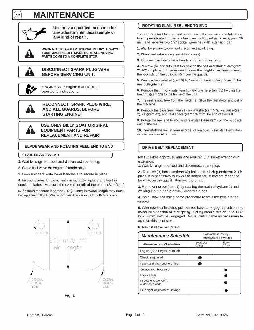
BLADE WEAR AND ROTATING REEL END TO END
1. Wait for engine to cool and disconnect spark plug.
2. Close fuel valve on engine. (Honda only)
3. Lean unit back onto lower handles and secure in place.
4. Inspect blades for wear, and immediately replace any bent orcracked blades. Measure the overall length of the blade. (See fig. 1)
5. If blades measure less than 3.0"(76 mm) in overall length they mustbe replaced. NOTE: We recommend replacing all the flails at once.
FLAIL BLADE WEAR
Use only a qualified mechanic forany adjustments, disassembly orany kind of repair .
DISCONNECT SPARK PLUG WIREBEFORE SERVICING UNIT.
WARNING: TO AVOID PERSONAL INJURY, ALWAYSTURN MACHINE OFF, MAKE SURE ALL MOVINGPARTS COME TO A COMPLETE STOP.
RECONNECT SPARK PLUG WIRE,AND ALL GUARDS, BEFORESTARTING ENGINE.
ENGINE: See engine manufactureroperator's instructions.
1717171717
Engine (See Engine Manual)
Check engine oil
Inspect and clean engine air filter
Grease reel bearings
Inspect belt
Maintenance Operation
Follow these hourlymaintenance intervals.Maintenance Schedule
Every25 hrs
Every Use(Daily)
ROTATING FLAIL REEL END TO END
USE ONLY BILLY GOAT ORIGINALEQUIPMENT PARTS FORREPLACEMENT AND REPAIR
NOTE: Takes approx. 10 min. and requires 3/8" socket wrench withextension.1. Wait for engine to cool and disconnect spark plug.
2 . Remove (3) lock nuts(item 62) holding the belt guard(item 21) inplace. It is necessary to lower the height adjust lever to reach thelocknuts on the guard. Remove the guard.
3. Remove the belt(item 9) by rotating the reel pulley(item 2) andwalking it out of the groove. Discard old belt
4. Install new belt using same procedure to walk the belt into thegroove.
5. With new belt installed pull bail rod back to engaged position andmeasure extension of idler spring. Spring should stretch 1" to 1.25"(25-32 mm) with bail engaged. Adjust clutch cable as necessary toachieve this extension.
6. Re-install the belt guard.
DRIVE BELT REPLACEMENT
Inspect for loose, worn,or damaged parts
Oil height adjustment linkage
To maximize flail blade life and performance the reel can be rotated endto end periodically to provide a fresh lead cutting edge. Takes approx. 20min. and requires two 1/2" socket wrenches with extension bar.
1. Wait for engine to cool and disconnect spark plug.
2. Close fuel valve on engine. (Honda only)
3. Lean unit back onto lower handles and secure in place.
4. Remove (6) lock nuts(item 62) holding the belt and shaft guards(item21 &22) in place. It is necessary to lower the height adjust lever to reachthe locknuts on the guards. Remove the guards.
5. Remove the drive belt(item 9) by "walking" it out of the groove on thereel pulley(item 2).
6. Remove the (4) lock nuts(item 60) and washers(item 68) holding thebearings(item 23) to the frame of the unit.
7. The reel is now free from the machine. Slide the reel down and out ofthe machine.
8. Remove the capscrew(item 71), lockwasher(item 57), reel pulley(item2), key(item 42), and reel spacer(item 10) from the end of the reel.
9. Rotate the reel end to end, and re-install these items on the oppositeend of the reel.
10. Re-install the reel in reverse order of removal. Re-install the guardsin reverse order of removal.
Fig. 1
Part No. 350245 Form No. F021302A
CR550, CR550H
Page 8 of 12
1818181818 PARTS DRAWINGR
Part No. 350245 Form No. F021302APage 9 of 12
item PARTS CR550 QTY CR550H QTYno. LIST Part No. Part No.
1 Pulley 2.5" OD 350256 1 350255 12 Pulley 5.5" OD X ¾ " 350206 1 350206 1
3 Wheel 8" Semi-Pneu White 350236 4 350236 44 Bar Strap 350211 1 350211 1
5 Rod Height Wa 350220 1 350220 16 Reel Flail Assy (see page xx for parts list and detailed dw g.) 350241 1 350241 17 Pulley Idler 2.75" 350114 1 350114 1
8 Arm Idler WA 350115 1 350115 19 Belt 5L X 34" 350207 1 350207 1
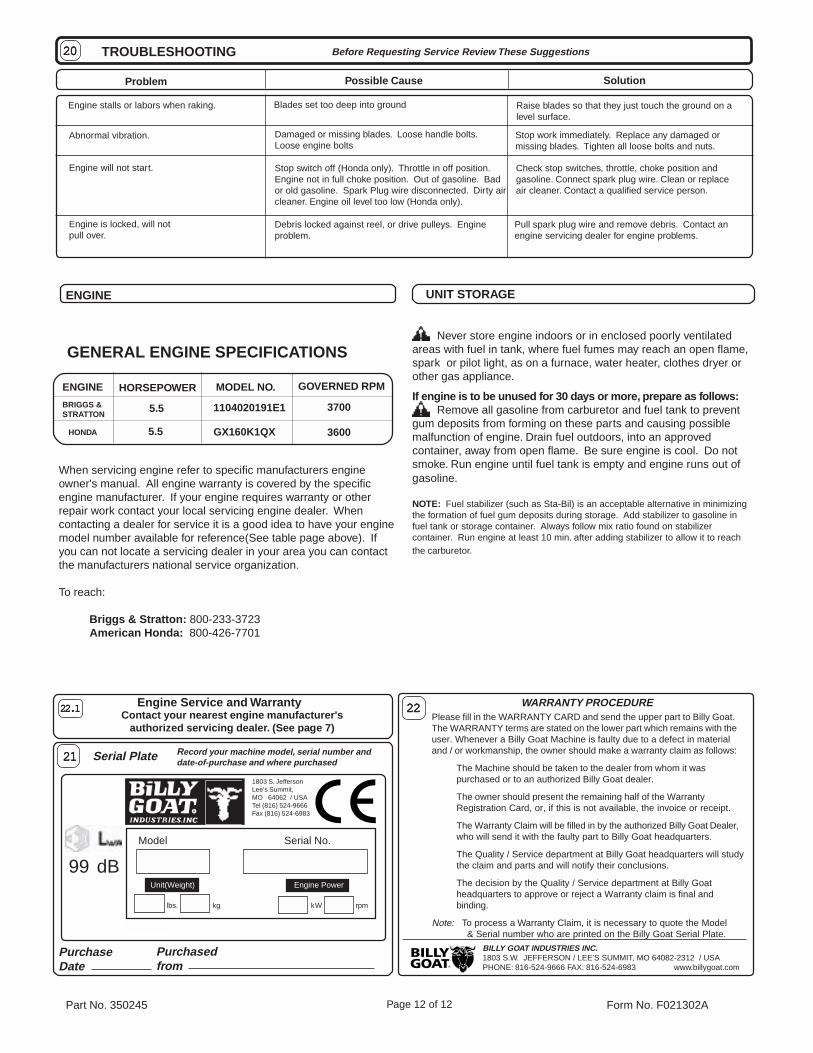
Debris locked against reel, or drive pulleys. Engineproblem.
Check stop switches, throttle, choke position andgasoline. Connect spark plug wire. Clean or replaceair cleaner. Contact a qualified service person.
Stop work immediately. Replace any damaged ormissing blades. Tighten all loose bolts and nuts.
Damaged or missing blades. Loose handle bolts.Loose engine bolts
Stop switch off (Honda only). Throttle in off position.Engine not in full choke position. Out of gasoline. Bador old gasoline. Spark Plug wire disconnected. Dirty aircleaner. Engine oil level too low (Honda only).
Pull spark plug wire and remove debris. Contact anengine servicing dealer for engine problems.
MODEL NO.
GENERAL ENGINE SPECIFICATIONS
HORSEPOWERENGINE
BRIGGS &STRATTON
HONDA 5.5
5.5 1104020191E1
GX160K1QX
GOVERNED RPM
3700
3600
ENGINE
When servicing engine refer to specific manufacturers engineowner's manual. All engine warranty is covered by the specificengine manufacturer. If your engine requires warranty or otherrepair work contact your local servicing engine dealer. Whencontacting a dealer for service it is a good idea to have your enginemodel number available for reference(See table page above). Ifyou can not locate a servicing dealer in your area you can contactthe manufacturers national service organization.
To reach:
Briggs & Stratton: 800-233-3723 American Honda: 800-426-7701
Never store engine indoors or in enclosed poorly ventilatedareas with fuel in tank, where fuel fumes may reach an open flame,spark or pilot light, as on a furnace, water heater, clothes dryer orother gas appliance.
If engine is to be unused for 30 days or more, prepare as follows:Remove all gasoline from carburetor and fuel tank to prevent
gum deposits from forming on these parts and causing possiblemalfunction of engine. Drain fuel outdoors, into an approvedcontainer, away from open flame. Be sure engine is cool. Do notsmoke. Run engine until fuel tank is empty and engine runs out ofgasoline.
NOTE: Fuel stabilizer (such as Sta-Bil) is an acceptable alternative in minimizingthe formation of fuel gum deposits during storage. Add stabilizer to gasoline infuel tank or storage container. Always follow mix ratio found on stabilizercontainer. Run engine at least 10 min. after adding stabilizer to allow it to reachthe carburetor.
UNIT STORAGE
R
Please fill in the WARRANTY CARD and send the upper part to Billy Goat.The WARRANTY terms are stated on the lower part which remains with theuser. Whenever a Billy Goat Machine is faulty due to a defect in materialand / or workmanship, the owner should make a warranty claim as follows:
The Machine should be taken to the dealer from whom it waspurchased or to an authorized Billy Goat dealer.
The owner should present the remaining half of the WarrantyRegistration Card, or, if this is not available, the invoice or receipt.
The Warranty Claim will be filled in by the authorized Billy Goat Dealer,who will send it with the faulty part to Billy Goat headquarters.
The Quality / Service department at Billy Goat headquarters will studythe claim and parts and will notify their conclusions.
The decision by the Quality / Service department at Billy Goatheadquarters to approve or reject a Warranty claim is final andbinding.
Note: To process a Warranty Claim, it is necessary to quote the Model & Serial number who are printed on the Billy Goat Serial Plate.