D E G E L M A N I N D U S T R I E S L T D.B O X 8 3 0 - 2 7 2 I N D U S T R I A L D R I V E ,R E G I N A , S K , C A N A D A , S 4 P 3 B 1FA X 306.543.2140 P H 3 0 6 . 5 4 3 . 4 4 4 71 . 8 0 0 . 6 6 7 . 3 5 4 5 D E G E L M A N . C O M
MANURE SPREADERM28 & M34
Serial Numbers 1010-1070
D E G E L M A N I N D U S T R I E S L T D.B O X 8 3 0 - 2 7 2 I N D U S T R I A L D R I V E ,R E G I N A , S K , C A N A D A , S 4 P 3 B 1FA X 306.543.2140 P H 3 0 6 . 5 4 3 . 4 4 4 71 . 8 0 0 . 6 6 7 . 3 5 4 5 D E G E L M A N . C O M
IMPORTANT:
READ MANUAL
TABLE OF CONTENTS - OPERATORS SECTION
Introduction 2
Overview 3
Safety 4
Preparation
Hook-up / Unhooking 6
Tractor & Spreader Preparation 7
Operation
Operation Safety & Preparation 8
Loading / Unloading 9
Optional Material Trailer Use 10
Transporting & Storage 11
Service & Maintenance
Safety & Specifications 12-13
Service Intervals 14
Adjustments 15-16
Repair 17-19
Troubleshooting 20
Parts Section - Table Of Contents 22
Warranty 42-43
-2-142657 - Manure Spreader (17-March-2016)
OPERATOR ORIENTATION - The directions left, right, front and rear, as mentioned throughout the manual, are as seen from the tractor drivers’ seat and facing in the direction of travel.
Introduction
CONGRATULATIONS Congratulations on your choice of a Degelman M28/M34 Manure Spreader to complement your farming operation. It has been designed and manufactured to meet the needs of a discerning agricultural market for the efficient and uniform spread distribution of manure. Use this manual as your first source of information about this machine. If you follow the instructions given in this manual, your machine will work well for many years.
Safe, efficient and trouble free operation of your Degelman Spreader requires that you and anyone else who will be operating or maintaining the Spreader, read and understand the Safety, Operation, Maintenance and Troubleshooting information contained within this Manual.
Keep this manual handy for frequent reference and to pass on to new operators or owners. Call your Degelman Dealer if you need assistance, information or additional copies of the manual.
Left Side
Front
Right Side
Rear
M28 & M34 SERIES MANURE SPREADERS
-3-142657 - Manure Spreader (17-March-2016)
Overview
The Degelman M28 & M34 Manure Spreaders are designed to efficiently and uniformly spread manure in widths of up to 60 feet in fields. Many of the features incorporated into this machine are the result of suggestions made by customers like you.
It is the owner’s or operator’s responsibility to read this manual carefully to learn how to operate the machine safely and how to set it to provide maximum efficiency. Safety is everyone’s business. By following safe operating practices, a safe environment is provided for the operator and bystanders.
The manual will take you step-by-step through your working day. By following the operating instructions in conjunction with a good maintenance program, your machine will provide many years of trouble-free service.
TO THE NEW OPERATOR OR OWNER
The Manure Spreader consists of a smooth walled material trailer with a floor chain drag system that pulls material steadily through a discharge gate at the rear of the machine where the dual vertical beaters process and distribute the material at high speeds in a uniform spread pattern.
The dual rear beaters are directly driven by gearboxes that are connected to the tractor’s PTO through drivelines.
The floor chain drag system is hydraulically controlled and incorporates a “Flow Control System”
adjusted by an incremental dial located on an in-cab control box. This controls the speed of which the chains drag material towards the rear beaters. The chain is driven by a hydraulic motor and gearbox located on the rear right-hand side of the spreader.
A rear gate is used to prevent material from packing into the rear beaters while loading and to prevent material
from falling out during transport. It is raised and lowered by two hydraulic cylinders.
The Safety Alert Symbol identifies important safety messages applied to the Manure Spreader and in this manual. When you see this symbol, be alert to the possibility of injury or death. Follow the instructions provided on the safety messages.
The Safety Alert Symbol means:
ATTENTION! BECOME ALERT!
YOUR SAFETY IS INVOLVED!
DANGER: Indicates an imminently hazardous situation that, if not avoided, WILL result in death or serious injury if proper precautions are not taken.
WARNING: Indicates a potentially hazardous situation that, if not avoided, COULD result in death or serious injury if proper precautions are not taken.
CAUTION: Indicates a potentially hazardous situation that, if not avoided, MAY result in minor or moderate injury if proper practices are not taken, or, serves as a reminder to follow appropriate safety practices.
Why is SAFETY important to YOU?
3 BIG Reasons:
•Accidents Can Disable and Kill •Accidents Are Costly •Accidents Can Be Avoided
Note the use of the Signal Words: DANGER, WARNING, and CAUTION with the safety messages. The appropriate Signal Word has been selected using the following guidelines:
SAFETY ALERT SYMBOL
SIGNAL WORDS
Safety
CAUTION
DANGER
WARNING
-5-142657 - Manure Spreader (17-March-2016)
1. Read and understand the Operator’s Manual and all safety signs before operating, maintaining or adjusting the Manure Spreader.
2. Install and properly secure all shields and guards before operating. Use hitch pin with a mechanical locking device.
3. Have a first-aid kit available for use should the need arise and know how to use it.
4. Have a fire extinguisher available for use should the need arise and know how to use it.
5. Wear appropriate protective gear. This list includes but is not limited to:
• A hard hat• Protective shoes with slip resistant soles• Protective glasses or goggles• Heavy gloves• Wet weather gear• Hearing protection• Respirator or filter mask
6. Clear the area of people, especially small children, and remove foreign objects from the machine before starting and operating.
7. Do not allow riders.
8. Stop tractor engine, set park brake, remove ignition key and wait for all moving parts to stop before servicing, adjusting, repairing or unplugging.
9. Review safety related items with all operators annually.
YOU are responsible for the safe operation andmaintenance of your Degelman Manure Spreader. YOU must ensure that you and anyone else who is going to operate, maintain or work around the Spreader be familiar with the operating and maintenance procedures and related SAFETY information contained in this manual.This manual will take you step-by-step through your working day and alerts you to all good safety practices that should be adhered to while operating this equipment.
Remember, YOU are the key to safety. Good safety practices not only protect you but also the people around you. Make these practices a working part of your safety program. Be certain that EVERYONE operating this equipment is familiar with the recommended operating and maintenance procedures and follows all the safety precautions. Most accidents can be prevented. Do not risk injury or death by ignoring good safety practices.
• Manure Spreader owners must give operating instructions to operators or employees before allowing them to operate the Spreader, and at least annually thereafter.
• The most important safety device on this equipment is a SAFE operator. It is the operator’s responsibility to read and understand ALL Safety and Operating instructions in the manual and to follow these. All accidents can be avoided.
• A person who has not read and understood all operating and safety instructions is not qualified to operate the machine. An untrained operator exposes himself and bystanders to possible serious injury or death.
• Do not modify the equipment in any way. Unauthorized modification may impair the function and/or safety and could affect the life of the equipment.
• Think SAFETY! Work SAFELY!
Safety
SAFETY GENERAL SAFETY
-6-142657 - Manure Spreader (17-March-2016)
The Manure Spreader should always be parked on a level, dry area that is free of debris and foreign objects. Follow this procedure when attaching:
1. Clear the area of bystanders and remove foreign objects from the machine and working area.
2. Make sure there is enough room to back the tractor up to the hitch pole.
3. Start the tractor and slowly back it up to the hitch point.
4. Stop the tractor engine, place all controls in neutral, set park brake and remove ignition key before dismounting.
5. Use the hitch pole jack to raise or lower the pole to align with the drawbar.
6. Install a drawbar pin with provisions for a mechanical retainer such as a Klik pin.
Install the retainer.
7. Install a safety chain between the tractor drawbar and the hitch pole.
8. Connect PTO driveline to tractor.
9. Connect the Flow Control cable plugs.
Preparation
HOOK-UP / UNHOOKING
10. Connect the Electrical Light plug.
11. Connect the hydraulics. To connect, proceed as follows:
• Use a clean cloth or paper towel to clean the couplers on the ends of the hoses. Also clean the area around the couplers on the tractor.
• Remove the plastic plugs from the couplers and insert the male ends.
NOTE: If the direction of motion is wrong, reverse the couplers.
12. Raise the hitch jack and rotate it 90º to place in its stowed position or relocate on jack bushing located on the side frame (see detail below).
13. When unhooking from the tractor, reverse the above procedure.
NOTE: Occasionally air may become trapped in the hydraulic circuit, making it necessary to “bleed” the circuit.
To perform this operation cycle the hydraulics several times or especially on older tractors, temporarily loosen an easily accessible hose fitting enough to allow any trapped air to escape while cycling the hydraulics. Retighten fitting.
PTO: Connect the PTO Driveline
• Check that the PTO driveline telescopes easily and the shield rotates freely
• Attach the driveline to tractor by:- Retracting the locking collar- Slide the yoke over the shaft- Push yoke until lock collar clicks into position
Connect the Hyd. lines
• Clean off couplers on hose & tractor with cloth
• Remove plugs & insert couplers
- Ensure pressure & return lines are matched up on same valve bank
Turn jack sideways for field position or relocate on side.
Install a safety chain between tractor drawbar and the hitch pole.
• Always park on a level surface clear of debris and obstacles.
Connect Flow Control
• Connect the cable plug ends from the flow control box to the valve assembly.
Connect Electrical Lights Plug
-7-142657 - Manure Spreader (17-March-2016)
Preparation
TRACTOR PREPARATION
Although there are no operational restrictions on the Manure Spreader when it is new, there are some mechanical checks that must be done to ensure the long term integrity of the unit. When using the machine for the first time, follow this procedure:
IMPORTANT: It is extremely important to follow all of the procedures especially those listed in the
“Before using” section below to avoid damage:
A. Before using:
1. Read Safety Info. & Operator’s Manual. Do not operate the spreader until the safety precautions in this manual and the decals on the spreader have been read and understood by the operator.
2. Check for proper assembly and adjustment and make sure all bolts are tight. All bolts were checked at the factory when assembled but need to be checked again as vibrations in shipment may loosen them slightly.
3. Complete steps in “Pre-Operation Checklist”.4. Lubricate the machine completely. Refer to the
Lubrication section of this manual (p.14). The initial grease was applied at the factory but proper maintenance is the user’s responsibility and must begin before the first use.
NOTE: Ensure driveline is properly lubricated, especially the driveline CV as it is not originally lubricated from supplier.
5. Operate the machine slowly for a period of time to run the chains in and confirm that all parts work freely.
B. After operating for 2 hours:
1. Retorque wheel bolts. 2. Check torque on the driveline cut-out clutch bolt (taper pin). Tighten to 75 ft-lbf (102 N·m) 3. Check all hardware. Tighten as required. 4. Check all hydraulic system connections. Tighten if any are leaking. 5. Tighten chain.
C. After operating for 8 hours:
1. Repeat Step B. 2. Go to the service schedule as outlined in the “Service & Maintenance” section.
SPREADER PREPARATION
Follow this procedure when selecting and preparinga tractor for use with the machine:
1. Use only a tractor of sufficient power and weight to adequately handle the machine. It is recommended that the tractor have at least 180 PTO horsepower for normal operating conditions.
2. It is recommended to pin the drawbar in its centre draft position.
3. Use only a drawbar pin with provisions for a mechanical retainer such as a Klik pin. Always install the retainer.
4. Always attach a safety chain between the tractor and the machine to prevent unexpected separation.
5. The drawbar pin to 1000 PTO shaft end dimension should be either:
16 inches for 1-3/8, 21 spline PTO models
20 inches for 1-3/4, 20 spline PTO models.
IMPORTANT: Do not use on a tractor equipped with a PTO shaft adapter to prevent
mismatching of PTO speeds and over telescoping of the driveline.
20 inches
16 inches
1-3/4 - 20 Spline
1-3/8 - 21 Spline
Recommended Wheel Bolt Torque Specs:
280-300 ft·lbs (380-405 N·m) -dry220-240 ft·lbs (300-325 N·m) -lub.Note: Recheck torque on wheel bolts after a couple of hours, and following day.
-8-142657 - Manure Spreader (17-March-2016)
Operation
OPERATING SAFETY
1. Read and understand the Operator’s Manual and all safety signs before using.
2. Stop tractor engine, place all controls in neutral, set park brake, remove ignition key and wait for all moving parts to stop before servicing, adjusting, repairing or unplugging.
3. Keep hands, feet, hair and clothing away from all moving and/or rotating parts.
4. Do not allow riders on the Manure Spreader or tractor during operation or transporting.
5. Keep all shields and guards in place when operating.
6. Clear the area of all bystanders, especially children, before starting.
7. Be careful when working around or maintaining a high-pressure hydraulic system. Ensure all components are tight and in good repair before starting.
8. Clean all reflectors, lights and the SMV sign (if applicable) before transporting on a highway or public road. Be sure to check with local highway authorities and comply with their lighting requirements.
9. Stay well back from machine when operating to prevent being hit by flying rocks and debris. Keep others a minimum of 500 ft (150m) away.
PRE-OPERATION CHECKLIST
It is important for both personal safety and maintaining the good mechanical condition of the machine that this pre-operational checklist be followed.
Before operating the machine and each time there-after, the following areas should be checked off:
1. Lubricate the machine completely. Refer to the schedule outlined in the “Service & Maintenance Section” of this manual.
2. Use only a tractor of adequate power (180hp minimum) and weight to handle the spreader.
3. Ensure that the machine is properly attached to the tractor using a drawbar pin with provisions for a mechanical retainer. Make sure that a retainer such as a Klik pin is installed.
4. Ensure the safety chain on the hitch is installed.
5. Check tires and ensure that they are inflated to the specified pressure: 65 psi (450 kPa) or 58 psi (400 kPa) for large tire option.
6. Check oil level in the tractor hydraulic reservoir. Top up as required.
7. Inspect all hydraulic lines, hoses, fittings and couplers for tightness. Tighten if there are leaks. Use a clean cloth to wipe any accumulated dirt from the couplers before connecting to the tractor’s hydraulic system.
8. Inspect all moving and rotating parts. Remove any debris that has become entangled in them.
9. Make sure that all guards and shields are installed and secured in position.
10. Check the oil level in the gearboxes. Top up as required.
11. Insure that the PTO driveline is securely attached on both ends and can telescope easily. Check that the PTO driveline shield rotates freely.
WARNING: Use extreme care when working around a high pressure hydraulic system. Make sure all connections are tight and all components are in good repair. Wear hand and eye protection when searching for suspected leaks.
-9-142657 - Manure Spreader (17-March-2016)
Operation
IMPORTANT: When parking the spreader for loading, put the tractor in PARK or NEUTRAL and apply the parking brake.
1. Fully Close Rear Hydraulic Gate
NOTES: - It is unlawful to allow any manure spillage to occur on public roadways. Do not heap load such that manure is allowed to fall off spreader during transporting on roadways.
- Always check the floor drag chain and slats to make sure they are not frozen to the bottom of the bed. Operating the spreader when the slats or chain are frozen to the bed may cause damage. Also make sure there are no lumps of manure frozen to the floor.
- It is recommended to make sure chains and table floor are operating properly before loading the spreader.
2. Load the Spreader - The moisture content will determine how full it can be loaded. Refer to the Specifications for capacity. Solid manure can generally be loaded level to slightly heaped. High moisture materials are heavier and may limit loading.
- Use front mesh cover when loading wet, slurry materials. Remove mesh cover for visibility, if desired, when spreading for coarser material.
LOADING
NOTE: Before starting the table, the operator should get the beaters up to speed and fully open the rear gate. This prevents the spreader from overworking itself from material being pulled up against the rear gate.
3. Start the Table Floor
Turn on power switch on the Control box.
Turn on the hydraulics used to start the table floor moving. This speed is adjusted with the “Flow Control Dial”.
The flow control dial adjusts the “table speed” at which material is being pulled towards the rear beaters. The slower the speed - the finer the spread as the rear beaters have more time to “process” the material. The typical starting speed on the flow control dial is 40 (based on spreading cattle manure). Operators may wish to slow this down a depending on preference or material being spread.
Note: At the end of the day it is recommended to turn off the power switch on the “Flow Control Box” to prevent possibility of battery drain.
4. Travel Speed - A suggested starting speed is between 4-5 mph. This can be adjusted to operator preference.
The effective spread is roughly 60ft (although thinned out material may cover distances of up to 100ft).
5. Lower Gate as Load Decreases
DANGER: Normally, the load itself blocks manure and loose materials from being thrown towards the front. As the load/pile gets reduced, the rotation of the rear beaters can throw some material forward, therefore it is strongly recommended to lower the rear gate about 1/3 of the way down to prevent debris from being projected towards the front.
UNLOADING CONTINUED...
1. Start up the Rear Beaters - Start the PTO and get the beaters running up to speed.
2. Fully Open Rear Gate - Fully extend the cylinders so the gate is fully open all the way to the top.
DANGER: If, at any time, abnormal vibrations occur, shut down machine, wait for all moving parts to stop, inspect machine, drivelines, and rear beaters for missing, jammed, or damaged components.
UNLOADING
IMPORTANT: Ensure all items under Operating Safety are followed and ensure all bystanders are a minimum of 500 ft (150m) away before operating!
-10-142657 - Manure Spreader (17-March-2016)
Operation
This manure spreader may also be used as a material trailer by removing the rear beater/frame assembly.
WARNING: Stop tractor engine, place all controls in neutral, set park brake, remove ignition key and wait for all moving parts to stop before servicing, adjusting, repairing or unplugging.
1. Disconnect/Remove rear Driveline
Before removing the rear frame assembly, the rear driveline must be disconnected and removed. Store in a safe location.
2. Disconnect (4) bolts on both sides (8 total).
3. Securely wrap a chain around rear beaters (above center of gravity).
4. With the aid of a front end loader, the “Rear
Frame Assembly” will then lift off. Store in a suitable, safe location.
5. The unit should now be ready to use as a
material trailer/wagon.
OPTIONAL MATERIAL TRAILER USAGE
1
2
3 & 4
The following is a recommended procedure that may help if the manure spreader becomes plugged or the PTO disengages:
1. Stop the Table Floor Disengage the hydraulics on that run the table
floor chains and turn off the flow control box.
2. Lower RPM After the PTO clutch dis-engages, the RPM has
to be lowered below 500 RPM in order for it to re-engage.
3. Reverse the Table Floor Direction Reverse the hydraulics used to start the table
floor moving in order to back material away from beaters. Stop table after material is backed away from beaters or if pile doesn’t move.
4. Re-start Beaters Bring beaters back up to regular speed.
5. Start Table Floor Chain Re-start the table floor moving again by turning
the hydraulics on in the proper direction.
If this above procedure does not solve the situation, closer inspection and possible manual unplugging may be required. Make sure to stop tractor and wait for all moving parts to stop before servicing or unplugging.
UNPLUGGING
FREEZING WEATHER OPERATION
• Before loading in freezing weather, make sure the apron chains and slats are not frozen to the floor, the spreader beaters are free to rotate and the rear gate moves freely up and down.
• At end of use, completely empty the last of the spreader contents. Clean any remaining debris from the spreader, the main drive, and the rear gate.
• Ensuring area is clear, slowly engage the PTO & run the spreader for a few minutes to clean out manure debris and to allow any remaining manure and the spreader to freeze dry.
• Run rear gate up and down to clean the gate slides. Park spreader with the gate halfway open.
WARNING: Stop tractor engine, place all controls in neutral, set park brake, remove ignition key and wait for all moving parts to stop before servicing, cleaning, adjusting, repairing or unplugging.
-11-142657 - Manure Spreader (17-March-2016)
Transporting & Storage
RIDERS
TRANSPORT SAFETY
• Read and understand ALL the information in the Operator’s Manual regarding procedures and SAFETY when operating the spreader in the field/yard or on the road.
• Check with local authorities regarding machine transport on public roads. Obey all applicable laws and regulations.
• Always travel at a safe speed. Use caution when making corners or meeting traffic.
• Make sure the SMV (Slow Moving Vehicle) emblem and all the lights and reflectors that are required by the local highway and transport authorities are in place, are clean and can be seen clearly by all overtaking and oncoming traffic.
• Clean off machine to ensure loose debris/materials do not fall from spreader while in transport.
• Keep to the right and yield the right-of-way to allow faster traffic to pass. Drive on the road shoulder, if permitted by law.
• Always use hazard warning flashers on tractor when transporting unless prohibited by law.
• Always use a pin with provisions for a mechanical retainer and a safety chain when attaching to a tractor or towing vehicle.
After the season’s use, completely inspect allmajor systems of the machine. Repair or replaceany worn or damaged components to preventunnecessary down time at the beginning of nextseason.
Since the unit can be used in extremely adverseconditions during the season, the machine shouldbe carefully prepared for storage to ensure that alldirt, mud, debris and moisture has been removed.
Follow this procedure when preparing to store:
1. Wash the entire machine thoroughly using a water hose or pressure washer to remove all dirt, mud, debris or residue. Manure is acidic and will damage paint and cause rusting of metal components.
2. Inspect all moving or rotating parts to see if anything has become entangled in them. Remove the entangled material.
3. Lubricate all grease fittings to remove any moisture in the bearings.
4. Run the machine slowly for 1 minute to distribute lubricant to all surfaces.
5. Inspect all hydraulic hoses, fittings, lines, couplers and valves. Tighten any loose fittings. Replace any hose that is badly cut, nicked or abraded or is separating from the crimped end of the fitting.
6. Touch up all paint nicks and scratches to prevent rusting.
7. Oil the exposed rams on the hydraulic cylinders to prevent rusting.
8. Select an area that is dry, level and free of debris.
STORAGE
STORAGE SAFETY
• Store unit in an area away from human activity.
• Do not permit children to play around the stored unit.
WARNING: Always check local transport height restrictions and confirm clearances before transporting.
We recommend lowering and securing the front guard assembly before transport:
1. Remove top hardware (both sides). Swing down
front guard and re-attach hardware.
2. Secure front guard as required.
3. IMPORTANT: Properly re-install front guard before use.
TRANSPORT HEIGHT
-12-142657 - Manure Spreader (17-March-2016)
Service & Maintenance
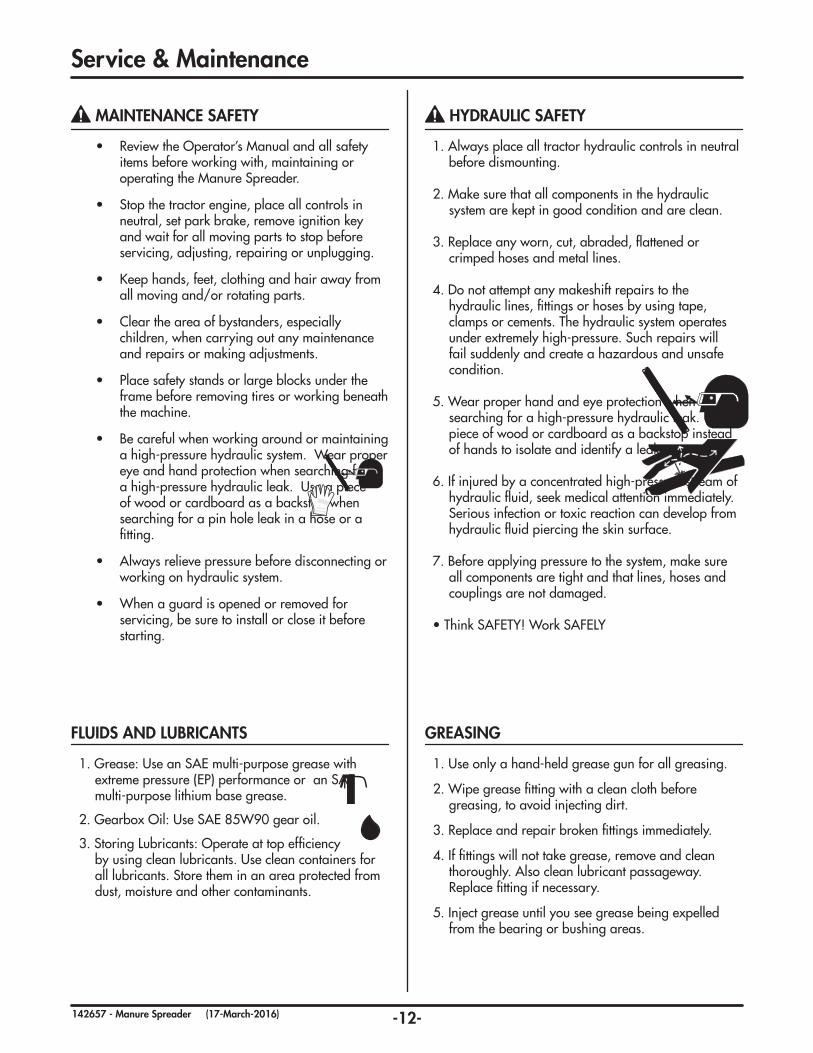
MAINTENANCE SAFETY
• Review the Operator’s Manual and all safety items before working with, maintaining or operating the Manure Spreader.
• Stop the tractor engine, place all controls in neutral, set park brake, remove ignition key and wait for all moving parts to stop before servicing, adjusting, repairing or unplugging.
• Keep hands, feet, clothing and hair away from all moving and/or rotating parts.
• Clear the area of bystanders, especially children, when carrying out any maintenance and repairs or making adjustments.
• Place safety stands or large blocks under the frame before removing tires or working beneath the machine.
• Be careful when working around or maintaining a high-pressure hydraulic system. Wear proper eye and hand protection when searching for a high-pressure hydraulic leak. Use a piece of wood or cardboard as a backstop when searching for a pin hole leak in a hose or a fitting.
• Always relieve pressure before disconnecting or working on hydraulic system.
• When a guard is opened or removed for servicing, be sure to install or close it before starting.
HYDRAULIC SAFETY
1. Always place all tractor hydraulic controls in neutral before dismounting.
2. Make sure that all components in the hydraulic system are kept in good condition and are clean.
3. Replace any worn, cut, abraded, flattened or crimped hoses and metal lines.
4. Do not attempt any makeshift repairs to the hydraulic lines, fittings or hoses by using tape, clamps or cements. The hydraulic system operates under extremely high-pressure. Such repairs will fail suddenly and create a hazardous and unsafe condition.
5. Wear proper hand and eye protection when searching for a high-pressure hydraulic leak. Use a piece of wood or cardboard as a backstop instead of hands to isolate and identify a leak.
6. If injured by a concentrated high-pressure stream of hydraulic fluid, seek medical attention immediately. Serious infection or toxic reaction can develop from hydraulic fluid piercing the skin surface.
7. Before applying pressure to the system, make sure all components are tight and that lines, hoses and couplings are not damaged.
• Think SAFETY! Work SAFELY
1. Use only a hand-held grease gun for all greasing.
2. Wipe grease fitting with a clean cloth before greasing, to avoid injecting dirt.
3. Replace and repair broken fittings immediately.
4. If fittings will not take grease, remove and clean thoroughly. Also clean lubricant passageway. Replace fitting if necessary.
5. Inject grease until you see grease being expelled from the bearing or bushing areas.
GREASING
1. Grease: Use an SAE multi-purpose grease with extreme pressure (EP) performance or an SAE multi-purpose lithium base grease.
2. Gearbox Oil: Use SAE 85W90 gear oil.
3. Storing Lubricants: Operate at top efficiency by using clean lubricants. Use clean containers for all lubricants. Store them in an area protected from dust, moisture and other contaminants.
FLUIDS AND LUBRICANTS
-13-142657 - Manure Spreader (17-March-2016)
TIRE SAFETY
1. Failure to follow proper procedures when mounting a tire on a wheel or rim can produce a blow out which may result in serious injury or death.
2. Do not attempt to mount a tire unless you have the proper equipment and experience to do the job.
3. Have a qualified tire dealer or repair serviceman perform required tire maintenance.
Service & Maintenance
TORQUE SPECIFICATIONS
CHECKING BOLT TORQUE
The tables shown below give correct torque values for various bolts and capscrews. Tighten all bolts to the torques specified in chart unless otherwise noted. Check tightness of bolts periodically, using bolt torque chart as a guide. Replace hardware with the same strength (Grade/Class) bolt.
IMPERIAL TORQUE SPECIFICATIONS(based on “Zinc Plated” values)
1. Check flare and flare seat for defects that might cause leakage.
2. Align tube with fitting before tightening.
3. Lubricate connection and hand tighten swivel nut until snug.
4. To prevent twisting the tube(s), use two wrenches. Place one wrench on the connector body and with the second tighten the swivel nut to the torque shown.
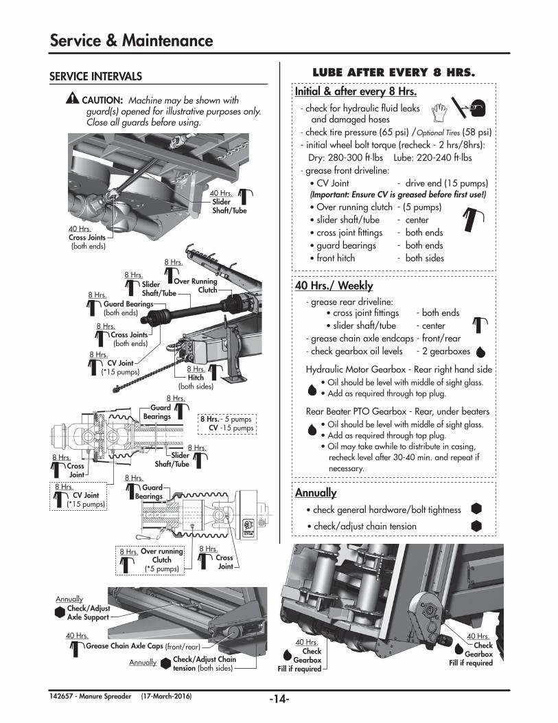
Hydraulic Motor Gearbox - Rear right hand side • Oil should be level with middle of sight glass.
• Add as required through top plug.
Rear Beater PTO Gearbox - Rear, under beaters • Oil should be level with middle of sight glass.
• Add as required through top plug. • Oil may take awhile to distribute in casing,
recheck level after 30-40 min. and repeat if necessary.
Annually
Annually
Check/Adjust Chain tension (both sides)
Check/Adjust Axle Support
Grease Chain Axle Caps (front/rear)40 Hrs.
Slider Shaft/Tube
8 Hrs. - 5 pumps CV -15 pumps
8 Hrs.
Cross Joint
8 Hrs.
CV Joint(*15 pumps)
8 Hrs.
Guard Bearings
8 Hrs.
Over running Clutch
(*5 pumps)
8 Hrs.Cross Joint
8 Hrs.
Guard Bearings
8 Hrs.
Annually • check general hardware/bolt tightness
• check/adjust chain tension
Hitch(both sides)
8 Hrs.
-15-142657 - Manure Spreader (17-March-2016)
Service & Maintenance
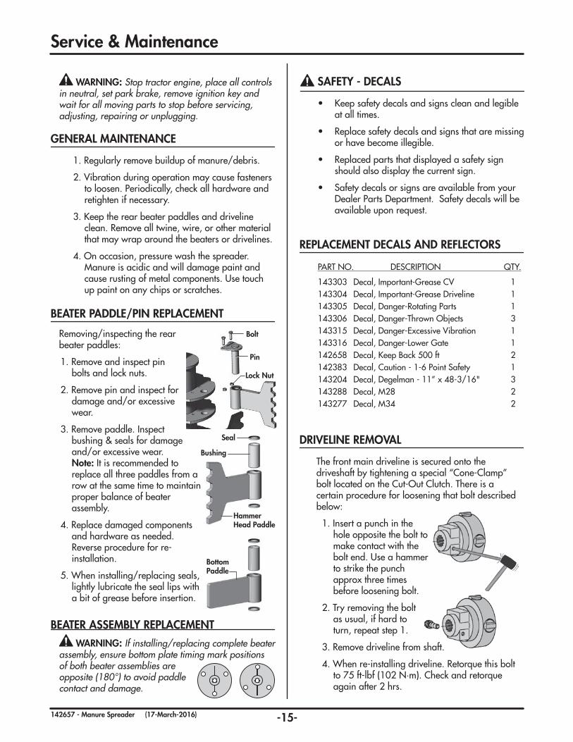
GENERAL MAINTENANCE
1. Regularly remove buildup of manure/debris.
2. Vibration during operation may cause fasteners to loosen. Periodically, check all hardware and retighten if necessary.
3. Keep the rear beater paddles and driveline clean. Remove all twine, wire, or other material that may wrap around the beaters or drivelines.
4. On occasion, pressure wash the spreader. Manure is acidic and will damage paint and cause rusting of metal components. Use touch up paint on any chips or scratches.
WARNING: Stop tractor engine, place all controls in neutral, set park brake, remove ignition key and wait for all moving parts to stop before servicing, adjusting, repairing or unplugging.
DRIVELINE REMOVAL
The front main driveline is secured onto the driveshaft by tightening a special “Cone-Clamp” bolt located on the Cut-Out Clutch. There is a certain procedure for loosening that bolt described below:
1. Insert a punch in the hole opposite the bolt to make contact with the bolt end. Use a hammer to strike the punch approx three times before loosening bolt.
2. Try removing the bolt as usual, if hard to turn, repeat step 1.
3. Remove driveline from shaft.
4. When re-installing driveline. Retorque this bolt to 75 ft-lbf (102 N·m). Check and retorque again after 2 hrs.
Note: It is recommended to replace all three paddles from a row at the same time to maintain proper balance of beater assembly.
4. Replace damaged components and hardware as needed. Reverse procedure for re-installation.
5. When installing/replacing seals, lightly lubricate the seal lips with a bit of grease before insertion.
Seal
Bushing
Hammer Head Paddle
Bottom Paddle
Pin
Lock Nut
Bolt
WARNING: If installing/replacing complete beater assembly, ensure bottom plate timing mark positions of both beater assemblies are opposite (180°) to avoid paddle contact and damage.
BEATER ASSEMBLY REPLACEMENT
-16-142657 - Manure Spreader (17-March-2016)
Service & Maintenance
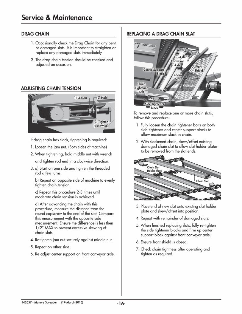
To remove and replace one or more chain slats, follow this procedure:
1. Fully loosen the chain tightener bolts on both side tightener and center support blocks to allow maximum slack in chain.
2. With slackened chain, skew/offset existing damaged chain slat to allow slat holder plates to be removed from the slat ends.
3. Place end of new slat onto existing slat holder plate and skew/offset into position.
4. Repeat with remainder of damaged slats.
5. When finished replacing slats, fully re-tighten the side tightener blocks and firm up center support block against front conveyor axle.
6. Ensure front shield is closed.
7. Check chain tightness after operating and tighten as required.
REPLACING A DRAG CHAIN SLAT
Chain Slat
Chain Slat Holder Plate
Center Support Block
Front Shield
Chain Slat
Chain Tightener
Bolt
Side Tightener Block
Front Conveyor
Axle
ADJUSTING CHAIN TENSION
If drag chain has slack, tightening is required:
1. Loosen the jam nut. (Both sides of machine)
2. When tightening, hold middle nut with wrench
and tighten rod end in a clockwise direction.
3. a) Start on one side and tighten the threaded rod a few turns.
b) Repeat on opposite side of machine to evenly tighten chain tension.
c) Repeat this procedure 2-3 times until moderate chain tension is achieved.
d) After advancing the chain with this procedure, measure the distance from the round capscrew to the end of the slot. Compare this measurement with the opposite side measurement. Ensure the difference is less then 1/2” MAX to prevent excessive skewing of chain slats.
4. Re-tighten jam nut securely against middle nut.
5. Repeat on other side.
6. Re-adjust center support on front conveyor axle.
1) Loosen 2) Hold
3) Tighten (clockwise)
DRAG CHAIN
1. Occasionally check the Drag Chain for any bent or damaged slats. It is important to straighten or replace any damaged slats immediately.
2. The drag chain tension should be checked and adjusted on occasion.
-17-142657 - Manure Spreader (17-March-2016)
Service & Maintenance
When cylinder repair is required, clean off unit, disconnect hoses and plug ports before removing cylinder.
DISASSEMBLY
1. Loosen lock ring and turn off end cap.
2. Carefully remove piston, rod and cap combination.
3. Disassemble piston from rod by removing lock nut.
NOTE: DO NOT clamp rod by chrome surface.
4. Slide off end cap.
5. Remove seals and inspect all parts for damage.
6. Install new seals and replace damaged parts with new components.
ASSEMBLY
1. Reinstall rod through end cap.
2. Secure piston to rod with lock nut. Torque to 225 ft-lb (305 N·m).
3. With cylinder body held gently in a vise, insert piston and rod combination using a slight rocking motion.
4. Thread lock ring fully onto barrel.
5. Turn end cap fully against lock ring then back off end cap to align ports.
6. Tighten lock ring against end cap using a punch and hammer.
HYDRAULIC CYLINDER REPAIR
COMMON DEGELMAN CYLINDER COMPONENTS
Barrel
RodAssembly
Lock Nut
Lock Ring
End Cap
Flat Washer
O-ring
Rod Seal
Wear Ring
Piston
PinAssembly
Shoulder Bolt
Piston Seals (5 part)
O-ring
Rod Wiper Seal
-18-142657 - Manure Spreader (17-March-2016)
Service & Maintenance
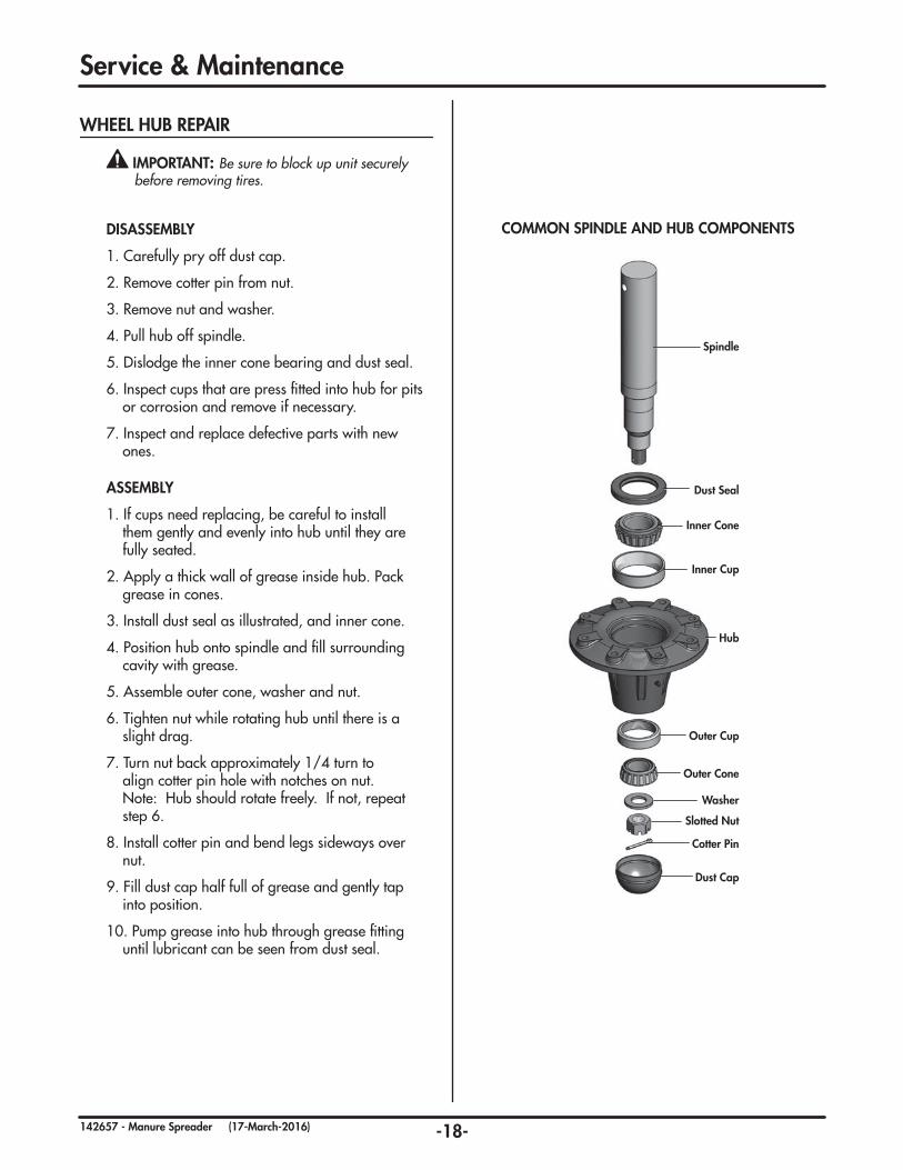
IMPORTANT: Be sure to block up unit securely before removing tires.
DISASSEMBLY
1. Carefully pry off dust cap.
2. Remove cotter pin from nut.
3. Remove nut and washer.
4. Pull hub off spindle.
5. Dislodge the inner cone bearing and dust seal.
6. Inspect cups that are press fitted into hub for pits or corrosion and remove if necessary.
7. Inspect and replace defective parts with new ones.
WHEEL HUB REPAIR
ASSEMBLY
1. If cups need replacing, be careful to install them gently and evenly into hub until they are fully seated.
2. Apply a thick wall of grease inside hub. Pack grease in cones.
3. Install dust seal as illustrated, and inner cone.
4. Position hub onto spindle and fill surrounding cavity with grease.
5. Assemble outer cone, washer and nut.
6. Tighten nut while rotating hub until there is a slight drag.
7. Turn nut back approximately 1/4 turn to align cotter pin hole with notches on nut. Note: Hub should rotate freely. If not, repeat step 6.
8. Install cotter pin and bend legs sideways over nut.
9. Fill dust cap half full of grease and gently tap into position.
10. Pump grease into hub through grease fitting until lubricant can be seen from dust seal.
Spindle
Inner Cone
Inner Cup
Hub
Dust Seal
Outer Cone
Outer Cup
Cotter Pin
Slotted Nut
Washer
Dust Cap
COMMON SPINDLE AND HUB COMPONENTS
-19-142657 - Manure Spreader (17-March-2016)
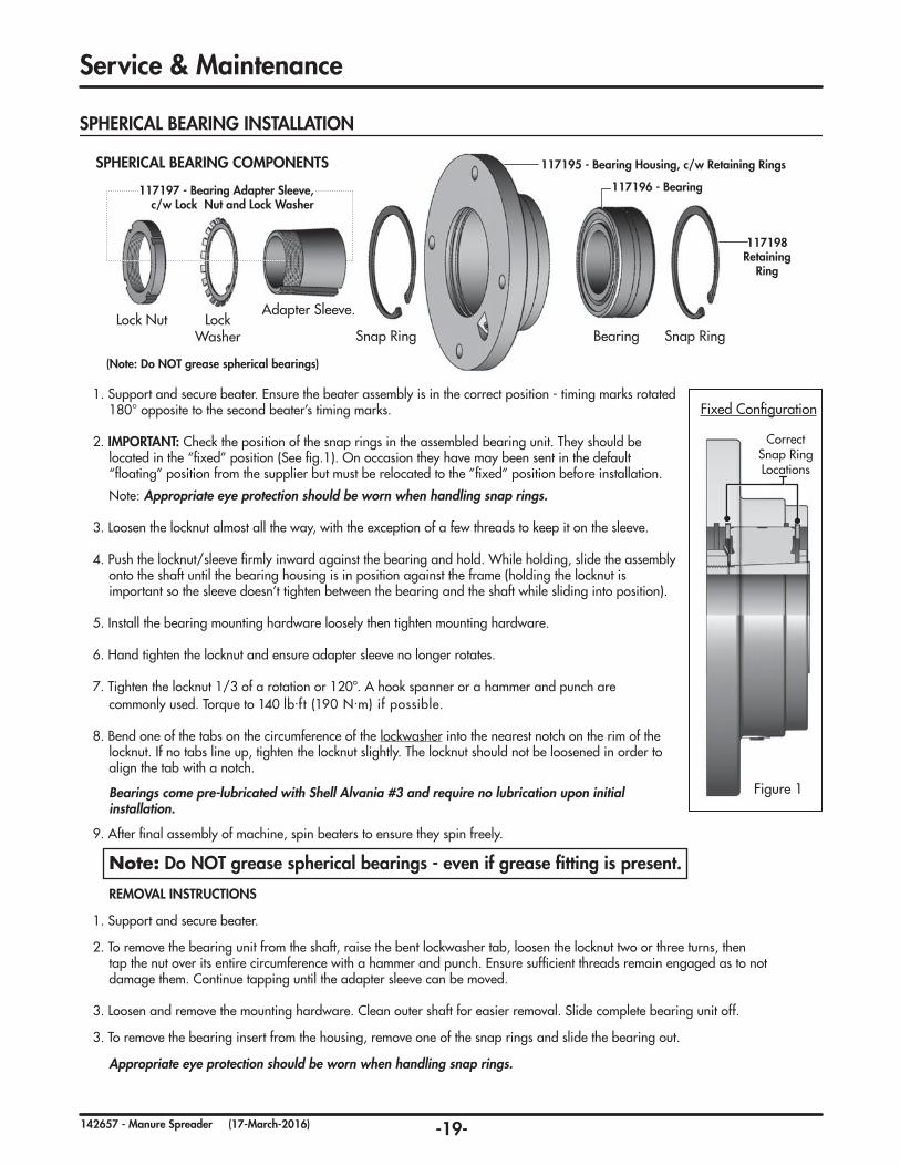
BearingSnap RingLock
WasherLock Nut
Snap Ring
Adapter Sleeve.
SPHERICAL BEARING COMPONENTS
Correct Snap Ring Locations
Fixed Configuration
Figure 1
SPHERICAL BEARING INSTALLATION
Service & Maintenance
1. Support and secure beater. Ensure the beater assembly is in the correct position - timing marks rotated 180° opposite to the second beater’s timing marks.
2. IMPORTANT: Check the position of the snap rings in the assembled bearing unit. They should be located in the “fixed” position (See fig.1). On occasion they have may been sent in the default “floating” position from the supplier but must be relocated to the ”fixed” position before installation.
Note: Appropriate eye protection should be worn when handling snap rings.
3. Loosen the locknut almost all the way, with the exception of a few threads to keep it on the sleeve.
4. Push the locknut/sleeve firmly inward against the bearing and hold. While holding, slide the assembly onto the shaft until the bearing housing is in position against the frame (holding the locknut is important so the sleeve doesn’t tighten between the bearing and the shaft while sliding into position).
5. Install the bearing mounting hardware loosely then tighten mounting hardware.
6. Hand tighten the locknut and ensure adapter sleeve no longer rotates.
7. Tighten the locknut 1/3 of a rotation or 120º. A hook spanner or a hammer and punch are commonly used. Torque to 140 lb.ft (190 N.m) if possible.
8. Bend one of the tabs on the circumference of the lockwasher into the nearest notch on the rim of the locknut. If no tabs line up, tighten the locknut slightly. The locknut should not be loosened in order to align the tab with a notch.
Bearings come pre-lubricated with Shell Alvania #3 and require no lubrication upon initial installation.
9. After final assembly of machine, spin beaters to ensure they spin freely.
Note: Do NOT grease spherical bearings - even if grease fitting is present.
REMOVAL INSTRUCTIONS
1. Support and secure beater.
2. To remove the bearing unit from the shaft, raise the bent lockwasher tab, loosen the locknut two or three turns, then tap the nut over its entire circumference with a hammer and punch. Ensure sufficient threads remain engaged as to not damage them. Continue tapping until the adapter sleeve can be moved.
3. Loosen and remove the mounting hardware. Clean outer shaft for easier removal. Slide complete bearing unit off.
3. To remove the bearing insert from the housing, remove one of the snap rings and slide the bearing out.
Appropriate eye protection should be worn when handling snap rings.
In the following section, we have listed some of the problems, causes and solutions that you may encounter. If you encounter a problem that is difficult to solve, even after having read through this troubleshooting section, please call your local dealer or distributor. Before you call, have this manual and the serial number from your unit ready.
PROBLEM
Chain came off sprocket
Oil accumulation on cylinder shaft.
Hydraulics are on but floor chain won’t engage.
PTO disengaged and beaters stopped working.
CAUSE
Freezing conditions.
Bent drag chain slat.
Loose chain.
External hydraulic leak.
Hydraulic cylinder leak.
Control box not properly connected or turned on.
Rear beaters were jammed, plugged, or stalled causing driveline clutch to disengage.
SOLUTION
Always check to make sure chain is not frozen before operating.
Replace bent or damaged slats.
Tighten chain. (Refer to Maintenance Section)
Disconnect & blow out lines with compressed air.
Repair as needed.
Flow control box must have power and be “on” in order to operate the floor chain.
PTO must be slowed to under 500 RPM before clutch will re-engage. Refer to “unplugging” procedure found on page 10 for more info.
-21-142657 - Manure Spreader (17-March-2016)
-22-142657 - Manure Spreader (17-March-2016)
Parts Section
IMPORTANT:
READ MANUAL
TABLE OF CONTENTS - PARTS SECTION
Overview 22
Frame Components 23
Walking Axle & Wheel Components 24
Hitch Pole Components 26
Rear Gate Components 26-27
Front Shield Components 28
Chain & Tightener Components 29
Rear Axle & Gearbox Components 30
Rear Beater Gearbox Components 31
Rear Frame & Beater Components 32-34
Driveline Components 35-37
Hydraulic Routing 38-39
Electrical Components 40-41
Warranty 42-43
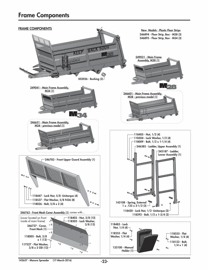
Frame Components (pg. 21)
Driveline Components (pg. 33-35)
Hydraulic Routing (pg. 36-37)
Driveline Components (pg. 33-35)
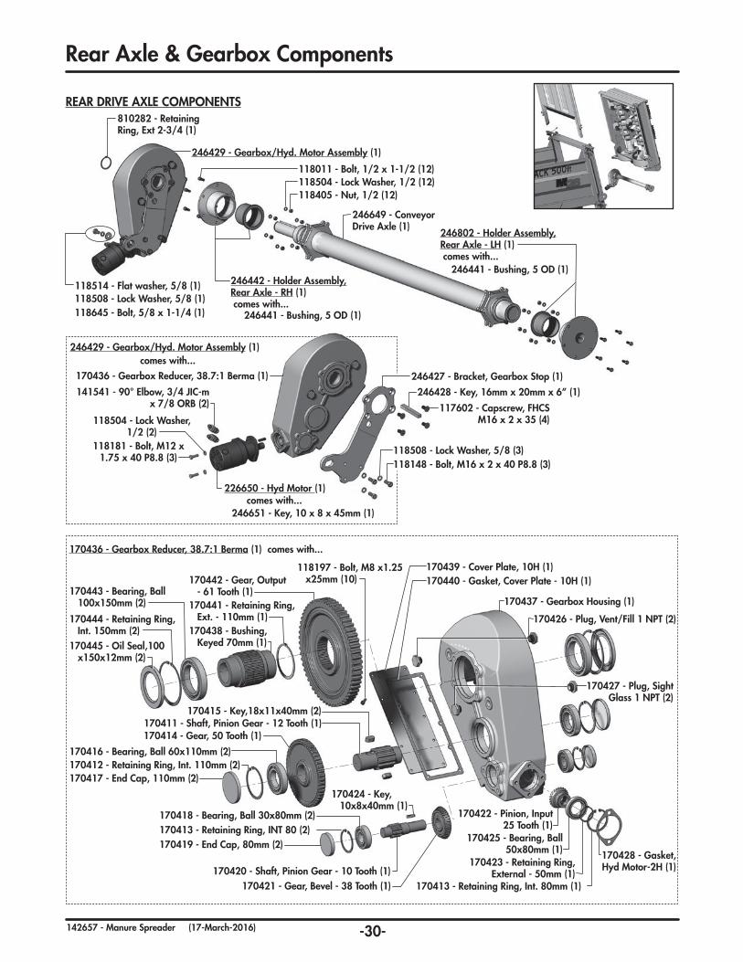
Rear Axle & Gearbox Components (pg. 28)
Lights & Electrical Components (pg. 38-39)
Driveline Front Shield (pg. 26)
Front Shield Components (pg. 26)
Hitchpole Components (pg. 24)
Walking Axle & Wheel Components (pg. 22)
Rear Gate Assembly& Cylinders (pg. 24-25)
Rear Frame & Beater Components (pg. 30-32)
Rear Beater Gearbox Components
(pg. 29)
Chain & Components(pg. 27)
Chain Tightener Components (pg. 27)
-23-142657 - Manure Spreader (17-March-2016)
246601 - Main Frame Assembly, M28 - previous model (1)
249031 - Main Frame Assembly, M28 (1)
246651 - Main Frame Assembly, M34 - previous model (1)
249041 - Main Frame Assembly, M34 (1)
New Models - Plastic Floor Strips
Frame Components
246763 - Front Mesh Cover Assembly (1) comes with...
HUB/SPINDLE COMPONENTS131396 - Hub/Spindle Assembly (4) comes with...
Recommended Wheel Bolt Torque Specs:
280-300 ft·lbs (380-405 N·m) -dry220-240 ft·lbs (300-325 N·m) -lub.Note: Recheck torque on wheel bolts after a couple of hours, and following day.
Recommended pressure: 58 psi (400 kPa)
Note: Larger wheel option replaces the walking axles and tires only. All other items are the same as the standard tire option (Spindles, wear washers, rod assembly and hardware.)
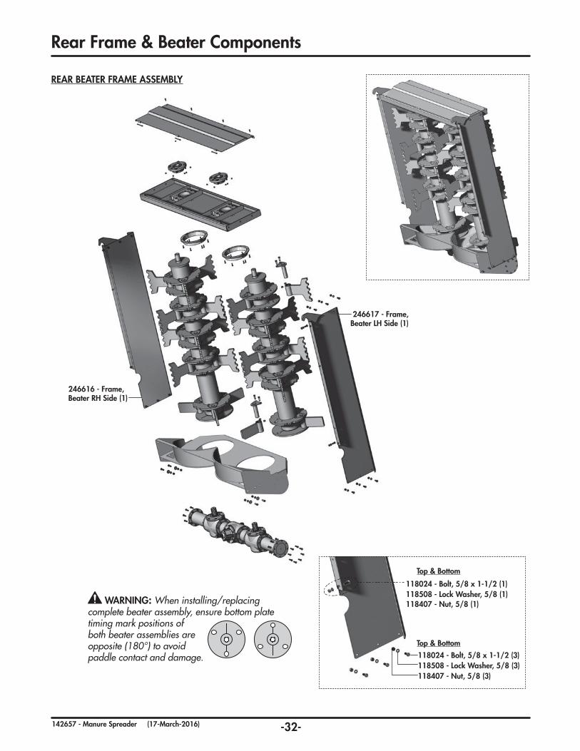
118407 - Nut, 5/8 (1) WARNING: When installing/replacing complete beater assembly, ensure bottom plate timing mark positions of both beater assemblies are opposite (180°) to avoid paddle contact and damage.
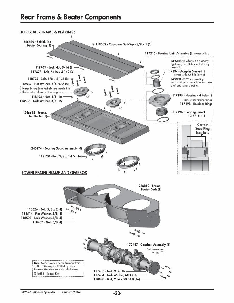
Note: Models with a Serial Number from 1000-1009 require 2” thick spacers between Gearbox ends and deckframe.
(246684 - Spacer Kit)
(Part Breakdown on pg. 29)
117195 - Housing - 4 hole (1)(comes with retainer rings
117198 - Retainer Ring)
117196 - Bearing, Insert - 2-7/16 (1)
117197 - Adapter Sleeve (1)(comes with nut & lock ring)
IMPORTANT: After nut is properly tightened, bend tab(s) of lock ring onto nut.
IMPORTANT: When installing, ensure adaptor sleeve is locked onto shaft and is not slipping.
Correct Snap Ring Locations
-34-142657 - Manure Spreader (17-March-2016)
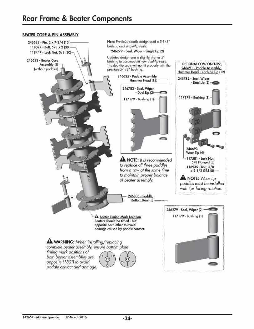
BEATER CORE & PIN ASSEMBLY
118027 - Bolt, 5/8 x 2 (30)246628 - Pin, 2 x 7-3/4 (15)
118447 - Lock Nut, 5/8 (30)
Beater Timing Mark LocationBeaters should be timed 180° opposite each other to avoid damage caused by paddle contact.
246805 - Paddle, Bottom Row (3)
246623 - Beater Core Assembly (2)
(without paddles)
Note: Previous paddle design used a 5-1/8” bushing and single-lip seals: 246279 - Seal, Wiper - Single Lip (2)
Updated design uses a slightly shorter 5” bushing to accomodate new dual-lip seals. The dual-lip seals will not fit properly with the previous 5-1/8” bushing.
Rear Frame & Beater Components
246279 - Seal, Wiper (2)
117179 - Bushing (1)
WARNING: When installing/replacing complete beater assembly, ensure bottom plate timing mark positions of both beater assemblies are opposite (180°) to avoid paddle contact and damage.
246625 - Paddle Assembly, Hammer Head (12)
246782 - Seal, Wiper - Dual Lip (2)
117179 - Bushing (1)
NOTE: It is recommended to replace all three paddles from a row at the same time to maintain proper balance of beater assembly. NOTE: Wear tip
paddles must be installed with tips facing rotation.
IMPORTANT: When installing, ensure tapered collar is locked onto shaft and not slipping
IMPORTANT: After nut is properly tightened, bend tab(s) of lock ring onto nut.
IMPORTANT: When attaching driveline onto shaft, tighten cut-out clutch bolt to to 75 ft-lbf (102 N·m). Check and retorque again after 2 hrs.
118447 - Lock Nut, 5/8 (2)
118537 - Flat Washer, 5/8 (4)
117220 - Bearing Assembly (1)
118026 - Bolt, 5/8 x 2 (2)
M28 - Qty (2) / M34 - Qty (3)
117210 - Bearing Assembly (1)
DRIVELINE & MOUNTING COMPONENTS
-36-142657 - Manure Spreader (17-March-2016)
Driveline Components
160352 - DRIVELINE SLIDER SHAFT, 37-48 - (Standard on models produced after June 2011)
160329 - Cross & Bearing, Kit (1)
160312 - Cross & Bearing, Kit (1)
160322 - Cross & Bearing, Kit (1)
160353 - Yoke, 1-3/4 x 20 Spline (1)
160327 - Overrunning Clutch & S4 (1)
160328 - Cut-out Clutch (1)
160326 - Slider Outer (1)
160356 - Yoke, Inboard S5 (1)
160361 - Guard Kit, Complete (1)
160355 - Double Yoke (1)
CV Joint(*15 pumps)
8 Hrs.
Note: CV is typically shipped without grease. Ensure CV and driveline are properly lubricated before first use and every 8hrs. (refer to maintenance section)
160320 - DRIVELINE SLIDER SHAFT - (Models produced before June 2011)
160362 - Cam (4)
160359 - Hub (1)
160363 - Bolt, Clamp-Cone (1)
160358 - Spring Pack (1)
Note: Cut-out Clutch bolt/taper pin needs to be checked and re-torqued to 75 ft-lbf (102 N·m) after first 2 hrs. of operation (to loosen or replace, refer to instructions in maintenance section on driveline removal)
Note: Install control box inside of tractor and connect tractor cable connector.
Note: Attach electrical wiring to hydraulic lines with plastic tie straps.
Note: Wrap hydraulic hoses in pairs with hose wrap (2), include electrical cable.
Note: Attach spiral wrapped hoses to hose holder assembly with two hose ties.
246514 - Flow Control Valve & Electrical Control Box Assembly (1) comes with...
129076 - Connector, Weather Pack - 2 Pin (m) (1)
246522 - Cable Connector Assembly - Tractor (1)
246517 - Tube, Heat shrink - 1/2 x 4 (2)
129043 - Crimp, Butt Splice - 16 GA (4)
141122 - Electrical Control Box (1)
246520 - Wire, 16/2 - 60” (1)
Black
Empty Red
Red
Red
Black
Black
Blue
Blue
129100 - Plug, Main Body -3P (1)
129102 - Connector, FM -AMP #F -A4200 (2)
246523 - Wire, 16 x 24”- BLK (1)
246524 - Wire, 16 x 24”- RED (1)246519 - Electrical Control Box & Wiring Cable Assembly (1) comes with...
129074 - Terminal, 16-14 GA (m) (2)
129078 - Seal, Weather Pack (2)
246808 - Hose Wrap, Spiral (2)
133009 - Hose Tie (2)
-42-142657 - Manure Spreader (17-March-2016)
2 YearLimited Warranty - Agricultural Products
Degelman Industries Ltd. (“Degelman”) warrants to the original purchaser of any new Degelman equipment, purchased from an authorized Degelman dealer, that the equipment will be free from defects in material and workmanship for a period of two (2) years from the date of delivery, for non-commercial use (including farm, institutional, government, and municipality) and (1) year from the date of delivery for commercial use. The obligation of Degelman to the purchaser under this warranty is limited to the repair or replacement of defective parts in the first year and to the provision, but not the installation of replacement parts in the second year. Degelman reserves the right to inspect any equipment or parts which are claimed to have been defective in material or workmanship.
This warranty limits its replacement or repair coverage to what is consistent with the warranty of Degelman’s suppliers of purchased components.
Replacement or repair parts installed in the equipment covered by this limited warranty are warranted for ninety (90) days from the date of delivery of such part or the expiration of the applicable new equipment warranty period, which ever occurs later. Warranted parts shall be provided at no cost to the user at an authorized Degelman dealer during regular working hours. Warranted replacement parts will either be replaced or rebuilt at Degelman’s discretion.
Disclaimer of implied warranties & consequential damages
This warranty shall not be interpreted to render Degelman Industries Ltd. liable for injury, death, property damage or damages of any kind, whether direct, consequential, or contingent to property. Without limiting the generality of the foregoing, Degelman shall not be liable for damages resulting from any cause beyond its reasonable control, including, without limitation, loss of crops, any expense or loss of labour, supplies, rental machinery or loss of use.
No other warranty of any kind whatsoever, express or implied is made with respect to this sale; and all implied warranties of merchantability and fitness for a particular purpose which exceed the obligations set forth in this written warranty are hereby disclaimed and excluded from this sale. This exclusion shall not apply in any jurisdiction where it is not permitted by law.
This limited warranty shall not apply:
1. If, in the sole opinion of Degelman, the unit has been subjected to misapplication, abuse, misuse, negligence accident or incorrect off-site machine set-up.
2. To any goods that have sustained damage or deterioration attributable to a lack of routine maintenance (eg. Check and Re-torque of fastening hardware, Hydraulic fluid purities, drive train alignments, and clutch operation)
3. If parts not made or supplied by Degelman have been used in the connection with the unit, if, in the sole judgement of Degelman such use affects its performance, safety, stability or reliability.
4. If the unit has been altered or repaired outside of an authorized Degelman dealership in a manner which, in the sole judgement of Degelman, affects its performance, safety, stability or reliability.
5. To expendable or wear items such as (eg. Harrow tines, Rock Picker and Rock Rake wear teeth and replaceable bushings and pins.) and any other items that in the company’s sole judgement are a wear item.
No employee or representative of Degelman Industries Ltd. is authorized to change this limited warranty in any way or grant any other warranty unless such change is made in writing and signed by the Degelman Service Manager.
This limited warranty is subject to any future availability of supply, which may directly affect Degelman’s ability to obtain materials or manufacture replacement parts.
Degelman reserves the right to make improvements in design or changes in specifications at any time, without incurring obligations to owners of equipment previously delivered.
This limited warranty is subject to compliance by the customer to the enclosed Retail Customer’s Responsibility Under Degelman Warranty.
Warranty
-43-142657 - Manure Spreader (17-March-2016)
Warranty
Make certain the warranty registration card has been forwarded to: Degelman Industries Ltd. Box 830 -272 Industrial Dr. Regina, SK, Canada S4P 3B1
Always give your dealer the serial number of your Degelman product when ordering parts or requesting service or other information.
The serial number is located on the machine as shown in the diagram below. In the space provided record the model number, the serial number and the date of purchase to assist your dealer in providing you with prompt and efficient service.
SERIAL NUMBER:
MODEL NUMBER:
DATE OF PURCHASE:
WARRANTY INFORMATION
Retail Customer’s Responsibility Under Degelman Warranty.
It is the retail customer and/or Operator’s responsibility to read the Operator’s Manual, to operate, lubricate, maintain and store the equipment in accordance with all instructions and safety procedures. Failure of the operator to read the operators manual is a misuse of this equipment.
It is the retail customer and/or operators responsibility to inspect the product and to have any part(s) repaired or replaced when continued operation would cause damage or excessive wear to other parts or cause safety hazard.
It is the retail customer’s responsibility to deliver the product to the authorized Degelman dealer, from whom he purchased it, for service or replacement of defective parts, which are covered by warranty. Repairs to be submitted for warranty consideration must be made within forty-five days of failure.
It is the Retail Customer’s responsibility for any cost incurred by the dealer for hauling of the product for the purpose of performing a warranty obligation or inspection.