64
Operator unit CDSA-D1-VX Description Software manual 560340 1501b [8039835]

Operator unit
CDSA-D1-VX
Description Software manual
560340 1501b [8039835]


Version ______________________________________________________________ 1501b
Designation ________________________________________________ GDCP-CDSA-SW-EN
Order no. ____________________________________________________________ 560340
(Festo AG & Co., 73726 Esslingen, 2015)
Internet: http://www.festo.com
E-mail: [email protected]
Reproduction, distribution and utilisation of this document, as well as the communication of its contents to others without explicit authorisation, is prohibited. Offenders will be held liable for damages. All rights reserved, in particular the right to file patent, utility model and registered design applications.
Festo GDCP-CDSA-SW-EN 1501b 3

Revisions index
Created by:
Handbook title: GDCP-CDSA-SW-EN
Filename:
File storage location:
Consec. no. Description Revisions index Date of revision
001 Created 1501b 7 July 2008
002 Correction 0909a 25 July 2009
003 Revision 1501b 15 Jan. 2015
Table 1.1 Directory of revisions
Specified directives/standards
Version status
EN ISO 13849-1:2008-12
Table 1.2 Directives/standards specified in the document
4 Festo GDCP-CDSA-SW-EN 1501b

Notes on this documentation
This documentation describes the function of the operator unit CDSA-D1-VX and its emulation through software as a PC application.
Identification of dangers and instructions on how to avoid them:
Warning
Dangers which can lead to death or serious injuries.
Caution
Dangers which can lead to slight injuries or to serious material damage.
Other symbols:
Note
Material damage or failure of function.
Recommendation, tip, reference to other documentation.
Necessary or useful accessories.
Information on environmentally friendly use.
Text designations:
• Activities that can be carried out in any order.
1. Activities which should be carried out in the specified sequence.
− General lists.
Festo GDCP-CDSA-SW-EN 1501b 5

Table of contents
Table of contents
1. Safety and requirements for product use .............................................................. 9
1.1 Safety .................................................................................................................. 9
1.1.1 General safety information ................................................................... 9
1.1.2 Intended use ...................................................................................... 11
1.2 Requirements for product use............................................................................ 12
1.2.1 Qualification of specialized personnel ................................................ 12
1.3 Service .............................................................................................................. 12
2. Introduction ........................................................................................................ 13
2.1 Starting the CDSA emulation ............................................................................. 13
3. Commissioning ................................................................................................... 15
3.1 Installation ........................................................................................................ 15
3.2 Setup menu ....................................................................................................... 15
3.2.1 Introduction to the setup menu .......................................................... 15
3.2.2 Masks in the setup menu ................................................................... 16
3.2.3 Equipment reset ................................................................................. 17
4. User interface ...................................................................................................... 18
4.1 General .............................................................................................................. 18
4.2 Philosophy of use .............................................................................................. 19
4.2.1 User interface on the operator unit ..................................................... 19
4.2.2 Status line .......................................................................................... 20
4.3 Overview of the menus and buttons ................................................................... 22
5. Message masks .................................................................................................. 24
5.1 Message classes ................................................................................................ 24
5.1.1 Message statuses .............................................................................. 25
5.2 Messages .......................................................................................................... 26
5.3 Message log ...................................................................................................... 27
5.3.1 Help for messages .............................................................................. 28
6 Festo GDCP-CDSA-SW-EN 1501b

Table of contents
6. Position mask ..................................................................................................... 29
7. Project mask ....................................................................................................... 32
8. Program mask ..................................................................................................... 34
8.1 Editing line ........................................................................................................ 36
8.2 Variable mask .................................................................................................... 37
8.3 Instruction mask ................................................................................................ 38
8.4 Parameter mask ................................................................................................ 39
8.5 Label list (dialogue) ........................................................................................... 41
8.6 Operator dialogue ............................................................................................. 41
9. Text editor mask ................................................................................................. 42
10. Setup mask ......................................................................................................... 43
10.1 Settings ............................................................................................................. 43
10.2 System information ........................................................................................... 43
10.3 Menu bar ........................................................................................................... 44
10.4 User ................................................................................................................... 45
10.4.1 Login dialogue ................................................................................... 45
10.4.2 User management – logged in (all users) ............................................ 46
10.4.3 User management – administration (only administrators) ................... 47
11. Variable mask ..................................................................................................... 49
11.1 Create new variable ........................................................................................... 51
12. I/O monitor ......................................................................................................... 52
12.1 Overview ........................................................................................................... 52
12.2 Detail ................................................................................................................. 53
13. Execution mask ................................................................................................... 56
14. Working with the operator unit ........................................................................... 57
14.1 Start/stop program ............................................................................................ 57
14.2 Creating a new program ..................................................................................... 57
14.3 Edit program ...................................................................................................... 58
14.3.1 Insert instruction ................................................................................ 59
14.3.2 Changing parameters ......................................................................... 60
Festo GDCP-CDSA-SW-EN 1501b 7

Table of contents
14.3.3 Modifying an expression in a program instruction .............................. 60
14.4 Teach/modify parameter values ........................................................................ 60
14.5 Messages .......................................................................................................... 61
14.5.1 Acknowledging the message in the message mask ............................. 61
Index ............................................................................................................................ 62
8 Festo GDCP-CDSA-SW-EN 1501b

1 Safety and requirements for product use
1. Safety and requirements for product use
1.1 Safety
1.1.1 General safety information
Warning
Project planning of the operator unit must be carried out by the machine manufacturer based on the danger-and-risk assessment.
The following safety aspects must be taken into account here:
− correct cable length for limiting the work area
− emergency stop switch required or permitted
− safety category sufficient for the respective application
The user must have the necessary level of training and must be familiar with the details of intended use corresponding to the operating instructions.
Warning
The enabling button is only suitable as a protective function when the person operating the enabling button realizes in time that there is a danger to persons and can take precautions to avoid dangers!
As an additional measure, reduced speed of the movement may be necessary. The permitted speed must be ascertained by means of a risk assessment.
Commands for statuses which bring danger cannot be initiated with an enabling button alone. A second start command is required here (pushbutton on the operator unit).
Only the person who operates the enabling button may be present in the danger zone.
Caution
Ineffective emergency stop with unplugged operator unit.
A not-connected operator unit in reach of the user can result in ineffective use of the emergency stop switch.
• Keep a not-connected operator unit outside the reach of the user.
Festo GDCP-CDSA-SW-EN 1501b 9

1 Safety and requirements for product use
Caution
In order to avoid malfunctioning or damage due to incorrect handling, you must always observe the following notes:
• The connection shaft must only be opened when the supply voltage is switched off. Otherwise, components may be damaged or undefined signal statuses may occur.
• Make sure that nobody can trip over the cable, thereby causing the device to fall onto the floor.
• Make sure that the cable is not squashed or damaged by other objects.
• Avoid laying the cable over sharp edges, which can abrade the cable sheath.
• Hang the device on the wall fastening intended for this purpose when it is not in use.
• Make sure that the device is not laid on the operating side, whereby operating elements may be mechanically damaged.
• Never lay the device on unstable surfaces or storage spaces. It might fall down and become damaged.
• Never place the device in the vicinity of sources of heat or direct sunlight.
• Avoid subjecting the device to mechanical shocks, excessive dust, humidity or strong magnetic fields.
• Do not use solvents, abrasive media or sponges for cleaning the housing, operating panel and operating elements. For cleaning, use a soft cloth moistened with water or a mild cleaning agent.
• Prevent objects and liquids from entering the inside of the device. Periodically check the protective covers on the device, completeness of the housing screws, as well as damage to the housing of the operator unit and cable throughfeed.
• The operator unit is equipped with a touch screen; operate it with your finger or the touch pin. The touch screen must on no account be operated with sharp objects, as these would damage the touch screen.
Note
Damage to the product from incorrect handling.
• Never unplug or plug in a product when powered.
• Observe the handling specifications for electrostatically sensitive devices.
10 Festo GDCP-CDSA-SW-EN 1501b

1 Safety and requirements for product use
1.1.2 Intended use The operator unit CDSA-D1-VX is intended for parameterisation and operation of machines and systems in conjunction with the multi-axis control system CMXR.
The operator unit is used for:
− parameterisation
− creation of FTL programs
− jogging and teaching
− observing
− control and
− diagnostics.
An enabling device and an emergency stop switch are available as safety functions. All safety functions are designed with two circuits, so that applications are possible up to safety category 3 PLd in accordance with EN ISO 13849-1.
• Use the operator unit only as follows:
− in perfect technical condition
− in original status without unauthorised modifications, except for the adaptations described in this documentation
− within the limits of the product defined through the technical data
− in an industrial environment.
Note
In the event of damage caused by unauthorised manipulation or other than intended use, the guarantee is invalidated and the manufacturer is not liable for damages.
Festo GDCP-CDSA-SW-EN 1501b 11

1 Safety and requirements for product use
1.2 Requirements for product use • Provide this documentation to the following persons:
− design engineer
− installer
− commissioner of the machine or system
• Comply with the specifications of the documentation. Follow all accompanying documentation and the documentation of any associated accessories.
• Take the following into consideration for the destination:
− applicable legal regulations
− regulations and standards
− regulations of the testing organisations and insurers
− national specifications
For correct and safe use:
• Observe all warnings and notes.
• Comply with all load limits for the product and the connected components.
1.2.1 Qualification of specialized personnel • The product should only be installed by specialized personnel with corresponding
qualifications.
The following knowledge is required:
− installation and operation of electrical control systems
− applicable regulations for operating safety-engineering systems
− applicable regulations for accident prevention and operational reliability
− documentation and mode of operation of the product.
1.3 Service • Consult your local Festo service or write to the following e-mail address if you have any
technical problems ( [email protected]).
12 Festo GDCP-CDSA-SW-EN 1501b

2 Introduction
2. Introduction This documentation describes the function of the operator unit CDSA-D1-VX and the CDSA emulation. The emulation is an implementation of the full function of the operator unit through a PC program.
Chapter 3 (Commissioning) applies only to the operator unit; all other chapters apply also for the CDSA emulation.
Warning
The CDSA emulation does not have the safety equipment of the operator unit. Emergency stop switch and enabling button are missing. You must be aware of this risk when using the CDSA emulation!
Small deviations in the function of the CDSA emulation are described at the corresponding position.
2.1 Starting the CDSA emulation The CDSA emulation runs on a standard PC, as used for the Festo Configuration Tool (FCT), for example. It is a functionally complete replacement for the operator unit, except for the limitation in the safety functions described above.
Call-up from the CMXR FCT plug-in
With the CMXR FCT plug-in started, the CDSA emulation can be activated via the menu option [Component] [Start CDSA emulation].
The following dialogue points out the limited safety functions:
The software is not started until confirmation is given through the “Start CDSA emulation” button.
Festo GDCP-CDSA-SW-EN 1501b 13

2 Introduction
Call-up from the Windows user interface
The emulation can also be started directly from the Windows interface using the normal methods for applications. The same dialogue as shown above appears first; upon confirmation, the emulation program starts.
Start screen of the CDSA emulation
14 Festo GDCP-CDSA-SW-EN 1501b

3 Commissioning
3. Commissioning
3.1 Installation The operator unit must be connected to the CMXR multi-axis controller via an Ethernet interface in order to enable commissioning and series operation. Connection is made via the CAMI-C interface housing. The connection circuitry can be found in the corresponding documentation.
Note
This documentation is part of the documentation package.
• It is essential that you observe the information and the safety instructions in the description “Mounting and installation” ( GDCP-CDSA-SY-…).
3.2 Setup menu The setup menu consists of the network setup and the display setup. The following settings can be made:
Network setup
− “IP-Address”
− “Subnet Mask”
− “Default Gateway”
− “Host IP”
Display setup
− “Backlight Time”
− “Brightness”
− “Touch Screen Calibration”
3.2.1 Introduction to the setup menu
If the button for activating the setup menu is not pressed, the operator unit will switch automatically to the setup menu after a timeout period of 2 minutes, providing a connection to the controller could be created.
During the boot procedure, “Enter Setup Mask?” appears for 2 seconds on the display. If
the button is held down during this time, you can access the setup menu.
• Set the desired values for the operator unit (IP-Address, Subnet Mask, Default Gateway) and the multi-axis controller (Host IP) in the setup menu.
• To activate the changes, press the “Save/Exit” button.
Festo GDCP-CDSA-SW-EN 1501b 15

3 Commissioning
The run-up will follow in the sequence as specified in the next chapter. Depending on the run-up procedure, appropriate messages will be shown on the display.
3.2.2 Masks in the setup menu
The values shown correspond to the factory setting when the device was shipped.
KeTop T50 FirmwareDisplay Setup
Backlighttime / on:
/off:
10
0
120
KeTop T50Vx_0.0705.10.2006
Save/Exit
+1 -1 +10 -10
Network Display
sec
sec
Brightness:
In order to modify the values in the entry fields in the above network/display setup menu by means of the soft keys “+1”, “+10”, “-1”, “-10”, the entry field to be modified must first be activated by touch. With the soft key “Save/Exit”, the new set values are saved in the EEPROM and the menu is ended.
16 Festo GDCP-CDSA-SW-EN 1501b

3 Commissioning
Menu option Explanation Default setting
IP-Address IP address of the operator unit 192.168.100.101
Subnet Mask Subnet mask of the operator unit 255.255.255.0
Default Gateway Default gateway of the operator unit 192.168.100.1
Host IP IP address of the multi-axis controller 192.168.100.100
Backlight Time Duration for dark switching of the display − On: Time from last input until background lighting is
switched to “low”. − Off: Time from switching the background lighting
from “low” until shut-down “off”.
On: 120 s Off: 0 s (deactivated)
Brightness Setting the display brightness (0 to 10) 10
Touch Screen Calibration
If you are already in the Setup menu, you should press the button for the Setup menu again in order to activate the touch screen calibration of the operator unit. Select the 3 reference points one after the other. Note: When calibrating the reference points, click the touch screen only very briefly with the touch pin. Pressing the reference points for too long will lead to faulty calibration. If the reference points lie too close to each other (assuming previous calibration was faulty), the touch screen calibration must be carried out again. When all three reference points have been entered, calibration is concluded automatically and the Setup menu appears again. The calibration procedure is stored with the “Save” button.
–
Table 3.1 Menu
3.2.3 Equipment reset If the equipment is to be restarted, to restart commissioning, for example, this can be done through simultaneously pressing the following button combination:
“Program mask”, “Message mask”, “Stop” ( Section 4.3)
This makes it possible to avoid interruption of the power supply of the operator unit.
Festo GDCP-CDSA-SW-EN 1501b 17

4 User interface
4. User interface
4.1 General The operator unit has a graphical user interface that has an easy-to-understand and intuitive design.
It is not necessary to have special knowledge of programming and computers in order to use the operator unit. All information is available in German and English. The language is selected within the software of the operator unit, without having to restart the system.
18 Festo GDCP-CDSA-SW-EN 1501b

4 User interface
4.2 Philosophy of use
4.2.1 User interface on the operator unit
1 Jog panel
2 Menu bar
3 Selected mask
4 Mask panel
5 Status line
Fig. 4.1 User interface, operator unit
Component Description
Menu bar Mask-specific, softkey panel with pop-up menus
Status line Fixed, always visible
Jog panel Axis display in relevant jog coordinate system (serves only to display; switching is carried out with the corresponding buttons on the operator unit. The buttons on the jog panel are transferred in real time to the controller).
Mask panel Switch between individual masks (serves only to display; switching is carried out with the corresponding buttons on the operator unit.
Table 4.1 Menu
1
2
3
5
4
Festo GDCP-CDSA-SW-EN 1501b 19

4 User interface
4.2.2 Status line
−
Top:
1 Operating mode
2 Program status
3 Name of the kinematics
4 Jog coordinate system
5 Override
6 Robot status
7 User level/write authorization
Bottom:
1 Project/program name
2 User icons (6)
3 Connection status
4 Time
5 Current message
6 Acknowledge current message
1
2
3
4
5
6
7
1
2
6
3
4
5
20 Festo GDCP-CDSA-SW-EN 1501b

4 User interface
Component Description
Operating mode The graphic user interface shows in this area the currently set operating mode for the selected robot. − Invalid No valid operating mode − HAND Manual override active − AUTO Automatic mode active
Program status − <empty>: No program being executed − STOP: Program stopped − RUN: At least one program is started
Project/program name Name of the currently running project and of the current program (separated by “,”), otherwise “-” is shown. If several programs have been started, the program containing the main pointer will be shown.
Kinematics Name of the selected kinematics.
Override Displays the override (speed of the robot).
Robot status Drives switched off Drives switched on, errors present
Ready to run
Write authorization and user level
Display of the user level of the currently logged-in user. If the user has write authorization, the field will be shown with a blue background. The write authorization enables the user to carry out commands and to modify values.
User icons User-defined icons can show various control statuses here, depending on the program (position 0 = outside left, position 5 = outside right).
Currently left: emergency stop status /
Last current message The last current message is shown in this field.
Jog coordinate system Display of the active jog coordinate system. The labelling of the jog panel also depends on this coordinate system.
Connection status Connection to the controller OK
Connection to the controller interrupted or does not exist
Connection to the controller not initialized
Message status At least one error message active <empty>: If no error message active (But warnings or information can be present) The last activated error message is always shown in a red line below the status line (the displayed message classes can be configured). These can be masked out with a click on the message text or acknowledged with the appropriate button in the line.
Time Display of the system time
Table 4.2 Contents of the status line
Festo GDCP-CDSA-SW-EN 1501b 21

4 User interface
4.3 Overview of the menus and buttons
Icon Description
Application mask (CANopenSDO, PLC Interface)
Service range (Setup, I/O monitor)
Variable mask
Project mask
Program mask
Position mask
Message mask
22 Festo GDCP-CDSA-SW-EN 1501b

4 User interface
Icon Description
Start/continue program
Interrupt all active programs
Jog buttons for axes 1 … 6 (move individual axis)
Reserved for extensions
Function button for extensions
Function button for extensions
Enable drives
Function button for extensions
Switching over the JOG coordinate system
Function button for extensions
Switch between “Step” and “Cont” for testing programs − Step for individual step − Cont for continuous operation (standard)
Increase or reduce override
Table 4.3 Overview
Festo GDCP-CDSA-SW-EN 1501b 23

5 Message masks
5. Message masks Messages triggered from the message system of the controller are shown in these masks.
− Messages Shows all current messages (message buffer)
− Message log Shows all messages which have occurred (report buffer)
In order to distinguish their treatment, messages are divided into 32 classes. In the HMI configuration, message classes can be grouped together as desired. By means of a selection list, the display can be limited to one group.
Message classes which are not assigned to any group are shown in the group “Other messages”. The group “All messages” is specified as standard by the system.
5.1 Message classes In order to distinguish their treatment, messages are divided into 32 classes. Classes 1 … 6 are reserved for the system (firmware), classes 7 … 32 are available for applications.
Icons are used for displaying the message classes and message statuses in the message masks.
Class Icon Description
1
Fatal firmware error. The controller is stopped. All processes are frozen.
2
Serious functional error. The controller stops and switches off the peripherals in a controlled manner.
3
Slight functional error. The application can react selectively.
4
Warnings of the firmware. The application can react selectively.
5
Information of the firmware. The application can react selectively.
6
Serious error in the application. The controller stops and switches off the peripherals in a controlled manner.
7 … 16
Medium and slight errors in the application, warnings and information. The application can react selectively.
17 … 32
For these classes, no message buffers are created, but only report buffers. They are written exclusively by the firmware and cannot be read by the application.
Without
Standard icon for all message classes which are not assigned their own icon.
Table 5.1 Icons
24 Festo GDCP-CDSA-SW-EN 1501b

5 Message masks
5.1.1 Message statuses The status of each message is also shown with each message in the message masks. The following statuses are possible:
Icon Status/description
Message serves only as information (no acknowledgment necessary).
Message must be acknowledged by the application.
Message must be acknowledged by the user.
Message must be acknowledged by the user and the application.
Message can be acknowledged either by the user or the application.
Message has been acknowledged by the application.
Message has been acknowledged by the user.
Table 5.2 Message statuses
Festo GDCP-CDSA-SW-EN 1501b 25

5 Message masks
5.2 Messages All current messages are shown in this mask. The list corresponds to the contents of the message memory.
Column Description
Class Displays the message class or the appropriate icon.
Time Time when the message occurred.
Status Shows the status icon of the message.
Description Display of the message text (translation text). This is provided by the controller.
Table 5.3 Explanations of the message window
Button/field Description
Group Here the displayed message list can be limited to one group.
Acknowledge Acknowledge selected message.
Display ID With this button, either the message text or the message key can be shown under Description. The message key consists of the component number, message number and instance number (e.g. component 2000, message 200, instance 17 results in the message key 2000_200_17).
Help When this button is pressed, a Help page for the marked message will be shown.
Acknowledge all All displayed messages will be acknowledged.
Table 5.4 Explanations of the message window
26 Festo GDCP-CDSA-SW-EN 1501b
5 Message masks
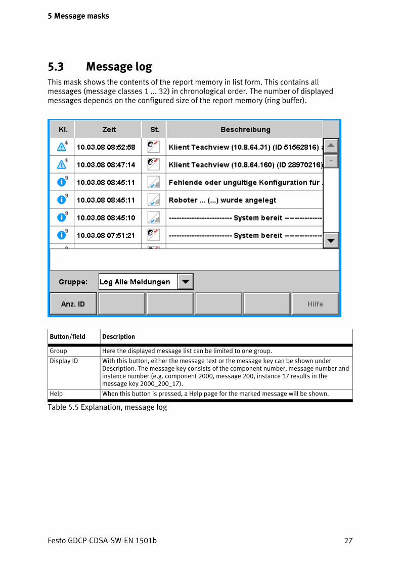
5.3 Message log This mask shows the contents of the report memory in list form. This contains all messages (message classes 1 ... 32) in chronological order. The number of displayed messages depends on the configured size of the report memory (ring buffer).
Button/field Description
Group Here the displayed message list can be limited to one group.
Display ID With this button, either the message text or the message key can be shown under Description. The message key consists of the component number, message number and instance number (e.g. component 2000, message 200, instance 17 results in the message key 2000_200_17).
Help When this button is pressed, a Help page for the marked message will be shown.
Table 5.5 Explanation, message log
Festo GDCP-CDSA-SW-EN 1501b 27

5 Message masks
5.3.1 Help for messages After actuation of the “Help” button, a separate dialogue with additional information on the selected message will be shown. The contents of the dialogue always have the same structure.
Field Description
Message: Message group and sub-group – separated by “_”
Text Text of the message with wildcard “%n” for any existing variable text parts.
Cause: Description of the possible causes of errors.
Effect: Effects of the cause of this message.
Measure: Remedy
Parameter n: Description of the variable parts embedded in the text.
Table 5.6 Layout of the help page for the messages
28 Festo GDCP-CDSA-SW-EN 1501b
6 Position mask
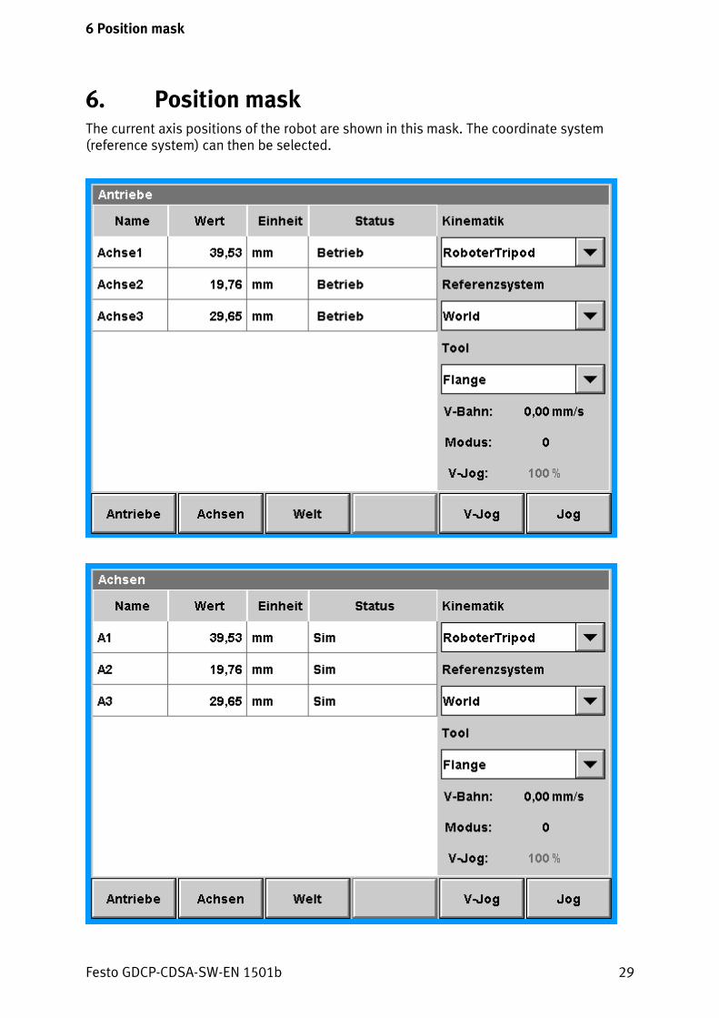
6. Position mask The current axis positions of the robot are shown in this mask. The coordinate system (reference system) can then be selected.
Festo GDCP-CDSA-SW-EN 1501b 29

6 Position mask
The actual values are shown in the table, dependent on the set display system (axes/joints/Cartesian). The number of actual values shown in the table also depend on the selected display coordinate system.
Column Description
Name Designation of the axis/joint or Cartesian designation.
Value Actual value of the axis or coordinate.
Unit Unit of the displayed value.
Status (only for axes)
Display of the axis statuses in text form. The following statuses can be displayed: − Sim: Axis is simulated − E+: Limit switch + reached − E–: Limit switch – reached − Nref: Not referenced − OK: Drives referenced Several statuses separated by hyphens can also be shown in this field.
Table 6.1 Explanation of the position mask
Next to the “World” button, the designation of the reference system will appear on the button when a reference system is selected. With this, the display can be activated to the Cartesian reference system.
30 Festo GDCP-CDSA-SW-EN 1501b

6 Position mask
Button/component Description
Kinematics Receives the name of the kinematics. No selection possible.
Reference system A reference system can be selected in this selection list. The selected reference system will be shown in the button to the right next to the “World” button.
V-path Display of the path speed.
Mode Not in use
V-jog (field) Display of the jog override.
Drives Selection of the Drives display system.
Axes Selection of the Axes display system.
World Selection of the World coordinate system.
Reference system Selection of the coordinate system of the reference system.
V-jog (button) Selection of the jog override (100 %, 50 %, 25 % 10 %, 1 ink, 0.1 ink).
Jog Switching over the Jog coordinate system between: − Axes − World − Reference system − Tool
Table 6.2 Explanation of the position mask
Selection when actuating the V-jog or Jog button.
Festo GDCP-CDSA-SW-EN 1501b 31

7 Project mask
7. Project mask All available projects with all programs will be shown in alphabetical sequence on this page. For a project to be displayed in this view, it must be in the application index in the controller.
Column Description
Name Name of the project (directory name of the FTL project).
Status The following statuses will be displayed: − --- : Project neither opened not loaded, inactive − Transmitted: Project has been opened, but not loaded, faulty − Loaded: Project opened and loaded − Active: Program started − Interrupted: Program stopped − Unloading: Project is now being closed − Loading: Project is now being loaded
Setting This column is not used.
Table 7.1 Explanation of the project mask
32 Festo GDCP-CDSA-SW-EN 1501b

7 Project mask
Button Description
Load The selected project is loaded. After a successful loading process, the status changes from --- or from transmitted to loaded. The load behaviour of the projects can be set in the configuration (only one project; only one project with automatic closing of the previously loaded project; or several projects simultaneously).
Open (project) Selected project opened, but not loaded. (Several projects can be opened in parallel.) After the project has been successfully opened, the status of the projects changes from --- to transmitted.
Open (program) Opens the program view of the selected program (only possible if program is transmitted). The relevant project will also be opened, if it has not yet been opened or loaded.
Close (project) Close open project. After successful closing, the status of the project changes from translated to ---.
Exit (program) Exits the selected active program. After successful exiting, the status changes from active or interrupted to ---.
Update The status of all projects is checked and updated, if necessary.
File Opens a menu with the following file operations: − Rename − Delete − Insert − Copy − New program (creates a new program in the current project) − New project − Import: Imports a project/program from a previously set directory/drive. When
a project is being imported, the selected project in the project mask is completely replaced.
− Export: Exports a project/program to a previously set directory/drive
Table 7.2 Explanation of the project mask
Festo GDCP-CDSA-SW-EN 1501b 33

8 Program mask
8. Program mask The contents of the program selected in the project mask can be shown and modified in this mask. In addition to modifying parameters, you can also insert or delete instructions in the program.
If transmission of the project which contains the program to be edited is faulty, the program mask cannot be opened. The incorrect program can be processed in the text editor mask.
For processing the programs, nested masks are used. These must be exited in the same sequence as they were opened. Depending on the activity carried out, the masks necessary for this will be opened in order to generate or modify step-by-step the desired program code.
The following masks and lists are used for creating a program:
− Program mask (main mask)
− Variable mask
− Instruction mask
− Parameter mask
− Label list (dialogue)
− Operator dialogue
1 Main pointer
2 Program name
3 Operating mode
4 Position of the main pointer
5 Selected line
Fig. 8.1 Program mask
The background of the program mask is represented in the following colours, depending on the loading status of the program:
− White background: Program is loaded
− Grey background: Program is not loaded, but only open
2
1
3
4
5
34 Festo GDCP-CDSA-SW-EN 1501b

8 Program mask
Button Description
Modify With this button, you can switch to the edit mode. An editing line will then be shown, in which the selected (blue) line can be edited. If only one change is possible at this position, the corresponding selection mask (e.g. variable mask) will also be displayed.
Macro Inserts the macro last selected in the instruction tree at the current cursor position (no program calls or logic commands).
New Opens the instruction mask. An instruction (program call, routine call, logic command) can be selected from the instruction tree and inserted in front of the cursor position in the program.
Set PC Sets the program pointer at the cursor position (blue background). At the next start command, the application runs from this line. When the action Set PC has been carried out, the previous program pointer position will be shown in brackets after the current position. This display is retained until an instruction is carried out. This button is only active when the program has been loaded.
Step/Cont Switch of the operating mode between individual step mode (Step) and sequence mode (Cont). This button is only active when the program is loaded. The set mode is displayed in the status line of the program mask.
Edit Opens a menu with the following commands: − Keyboard: Opens a keyboard window in which the selected line of the opened
program can be edited. − Subprogram: Opens the marked subprogram in the program mask. − Back: Closes the subprogram opened in the program mask. The main program, from
which this subprogram has been opened, will be shown again in the program mask. − Format − Search − Commend/delete comment: A comment mark is set or deleted at the beginning of
the current line (none of the instructions in the line will be taken into consideration).
− Deactivate/activate: A disable comment mark (##) will be inserted (or deleted) at the beginning of the current line. Deactivated instructions still exist in the execution structure, but are not carried out. If the instructions contain expressions, named elements in these expressions will nevertheless be checked for syntax. Therefore, variables in deactivated expressions cannot simply be deleted (e.g. cleaning up variables).
Selection Opens the selection menu with the following commands: − Select all − Cut − Copy − Insert
Delete Removes the program line at the cursor position.
Undo With this button, the last activity can be cancelled. Here only the activities insert, replace or remove are considered.
Table 8.1 Explanation of program mask
Festo GDCP-CDSA-SW-EN 1501b 35

8 Program mask
8.1 Editing line When the Modify button is pressed, the editing line is shown in the lower part of the program mask. The selected line of the opened program can be edited in the editing line. The activities necessary for this will be shown in the menu bar.
Button Description
Arrow keys (buttons)
The range to be modified (blue background) can be selected with the arrow keys.
Modify A corresponding selection mask (e.g. variable mask) will be shown, depending on the selected part of the instruction.
Keyboard Opens the virtual keyboard for direct entry of the instruction.
Cancel Exits the editing mode without modification.
Insert The modifications are inserted in the selected line of the program and the editing mode is exited.
Table 8.2 Explanation of the editing line
36 Festo GDCP-CDSA-SW-EN 1501b

8 Program mask
8.2 Variable mask The variable mask can be opened with Modify if a variable or the corresponding position of a new expression has been selected in the editing line. The variable mask serves to select variables. Only the variables of the opened program and the variables lying above it (global and project-wide variables) will be shown in the table. The display can be filtered according to the different variable types. In the type filter, only the variable types possible in this position in the program will be offered for selection.
The variable table displayed and the menu bar are identical with the variable mask. The variable mask can be closed without modification with the Cancel button. With the OK button, the modification made at the marked position in the editing line is transferred and the variable mask closed.
Festo GDCP-CDSA-SW-EN 1501b 37
8 Program mask
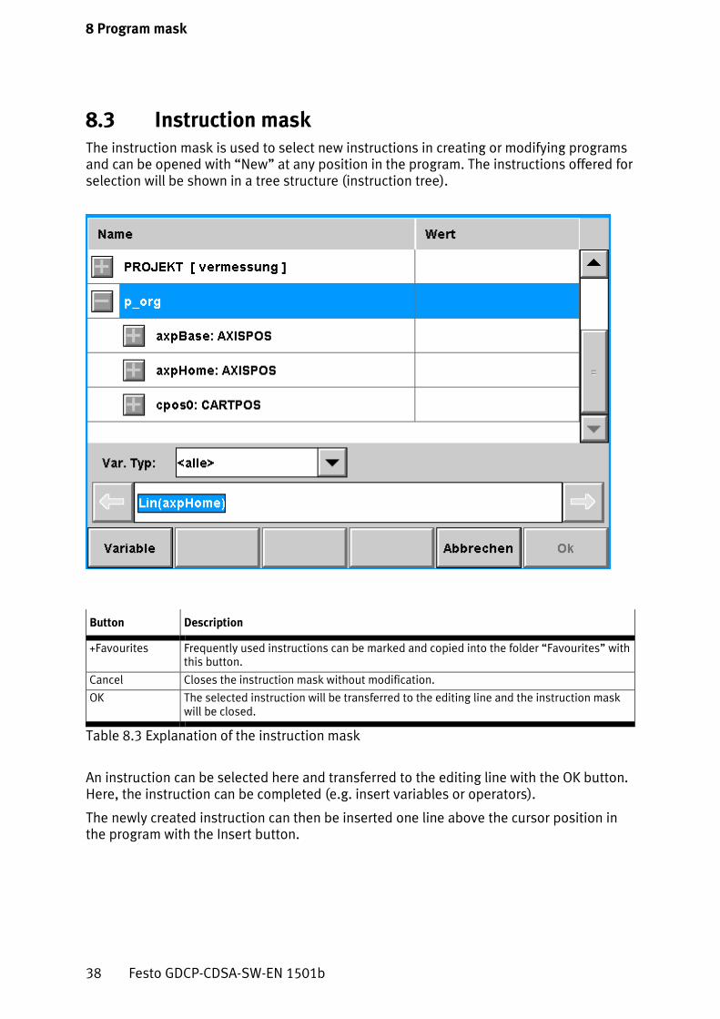
8.3 Instruction mask The instruction mask is used to select new instructions in creating or modifying programs and can be opened with “New” at any position in the program. The instructions offered for selection will be shown in a tree structure (instruction tree).
Button Description
+Favourites Frequently used instructions can be marked and copied into the folder “Favourites” with this button.
Cancel Closes the instruction mask without modification.
OK The selected instruction will be transferred to the editing line and the instruction mask will be closed.
Table 8.3 Explanation of the instruction mask
An instruction can be selected here and transferred to the editing line with the OK button. Here, the instruction can be completed (e.g. insert variables or operators).
The newly created instruction can then be inserted one line above the cursor position in the program with the Insert button.
38 Festo GDCP-CDSA-SW-EN 1501b

8 Program mask
8.4 Parameter mask The parameters of a macro can be processed in the parameter mask. Creating new parameters, entering values and teaching are possible here.
Use of the parameter mask is described in more detail in chapter 14 Working with the operator unit.
In addition to the designation, icons which describe the validity range of the parameter are also shown in the parameter list.
Festo GDCP-CDSA-SW-EN 1501b 39

8 Program mask
The following icons are used for displaying the validity range:
Icon Validity range
L Local (in the relevant program)
P Project (in all programs of the project)
G Global (parameter in the “global” project)
S Global (system variable)
Table 8.4 Icons
Button Description
Variable Opens a submenu with the following entries: − Selection: Opens the variable mask for selecting a different variable. Only the
variables possible at this position are offered for selection. − New: Opens a dialogue for creating a new project variable. In this dialogue, a
variable name with type-dependent prefix can be specified with the “Suggestion” button.
− Keyboard: The name of a variable can be entered here directly via the keyboard.
Teach If variable values in the column Value have been modified, they can be accepted with Teach.
Remove value The value of the selected parameter can be removed with this button.
Value Direct entry of the value (constant) for parameters with which a variable or constant can be specified. The corresponding input option is offered dependent on the variable type.
Cancel Closes the parameter mask without modification.
OK The parameters are accepted, and the parameter mask is closed.
Table 8.5 Explanation of program mask
If a component of a module is to be used as a parameter, it must be inserted in the variable mask via the Variable button ( 8.2 Variable mask).
40 Festo GDCP-CDSA-SW-EN 1501b

8 Program mask
8.5 Label list (dialogue) The label list is a list with all jump destinations within the displayed program. You can select a line from this list to create a jump instruction. The label list can be opened with Edit, if the relevant position in the editing line has already been marked.
8.6 Operator dialogue Arithmetical, logical and comparison operators for creating expressions are offered in this dialogue. The operator dialogue can be opened with “New”, if the relevant position in the editing line has already been marked.
Festo GDCP-CDSA-SW-EN 1501b 41

9 Text editor mask
9. Text editor mask A defective program can be edited with this mask. The error messages are shown in the lower part of the mask. When an error message is selected, the cursor is placed in the relevant line of the program. Compared with the program mask, the program can only be edited through direct entry via the alphanumerical keyboard (touch screen keyboard). Help masks, such as the variable mask or instruction mask, are not available in the text editor mask.
The text editor mask is shown automatically when an incorrect program is loaded or opened. The program remains open in the mask until all errors have been rectified or the relevant project has been unloaded. An already open text editor mask can be displayed again via the main menu (submenu option next to the program mask).
Menu button Description
Edit Edit the current line using an alphanumeric keyboard.
Transfer Transfers the project belonging to the displayed program.
Undo The last action is undone. Here only the activities insert, replace or remove are considered.
Insert Inserts a new line above the selected program line.
Delete Deletes the selected program line.
Table 9.1 Explanation of the text editor mask
42 Festo GDCP-CDSA-SW-EN 1501b

10 Setup mask
10. Setup mask Settings can be modified and system information can be shown in the setup mask. A status report can also be triggered and the system restarted in this mask.
10.1 Settings Field Description
Language A system language can be selected in this list. In addition to this manual selection, a predefined language can be assigned to each user via the user management. At the start of the visualization, the language will be loaded to the first position in the selection list.
Date/time The system time and the current date of the controller can be set here. These are managed and saved centrally in the controller.
User Displays the current logged-in user, including user level.
Table 10.1 Settings of the setup mask
10.2 System information
Field Description
CDSA-IP Displays the IP address of the operator unit.
CMXR-IP Displays the IP address of the controller.
System version Displays the system version of the controller.
TC memory utilization Specifies memory utilization in %
Table 10.2 Settings of system information
Festo GDCP-CDSA-SW-EN 1501b 43

10 Setup mask
10.3 Menu bar
Button Description
User Opens the dialogue to register a user or user management if a user is already logged in.
Display Sets brightness and contrast of the display.
System Opens a submenu with 4 entries: − HMI Restart: Restarts the operator unit (after acknowledgment) − Soft Restart: Restarts the controller − Restart: Restarts the controller and the operating system − Switch off: Switches the controller off.
Block Blocks the touch operation for a specific time.
Report Opens a submenu with 2 entries: Create:
After acknowledgement of the “State Report” dialogue, the report is created and also saved to the memory card of the CMXR. Successful creation is displayed with specification of the complete file name. Example: (/harddisk0/protocol/statusreport/starep_002.tgz) Export: Previously created status reports can be saved here on a USB storage medium. In a dialogue, the user can select one or all status reports for saving. A USB storage medium on the CMXR or CDSA can be selected as target. Exception: The CDSA emulation can store reports only on the USB storage medium of the multi-axis control system! If “CDSA” is selected, an error message is displayed.
Table 10.3 Settings of the system information
44 Festo GDCP-CDSA-SW-EN 1501b

10 Setup mask
10.4 User When the “User” button is pressed, the login dialogue appears. The total function range will only be available to the administrator.
If the user management is accessed through a guide system, the log-in dialogue or the user management cannot be opened. The user logged in at the guide system is automatically accepted.
10.4.1 Login dialogue The login dialogue is required for changing the user and/or his rights.
Selection of a user from the list
Input of the password assigned to the user
Request write authorisation
Festo GDCP-CDSA-SW-EN 1501b 45

10 Setup mask
Input field/checkbox Description
User Here you can select a user from a predefined list. This is defined by the administrator.
Password Hidden entry of the password through the keyboard.
Write authorisation If this check box is set, the displayed user receives write authorisation.
Logout With this button, a user can log out from the system. After that, the “default user” is active with its rights.
Table 10.4 Explanation of the login dialogue
In the “User” combo box, selection can be made from the list of logged-in users. When the correct password is entered and “OK” is pressed, the user is logged in. Switching of language or level can also take place here.
10.4.2 User management – logged in (all users) The logged-in user is shown on this page.
Column/button Description
User Name of the logged-in user.
Station IP address of the CDSA or of the CDSA emulation computer.
Level User level of the logged-in user.
Write An active checkbox grants the user write authorisation
Table 10.5 Explanation of the user management - logged in
46 Festo GDCP-CDSA-SW-EN 1501b

10 Setup mask
10.4.3 User management – administration (only administrators) On this page, new users can be created and existing users modified or deleted.
Column/button Description
User Shows the names of the users defined in the controller.
Level User level
Language Standard language of the user.
New Opens a dialogue in which a new user can be defined with all required settings.
Delete Deletes selected users in the list after acknowledgment. The user “Administrator” cannot be deleted.
Edit Opens a dialogue in which the user profile of the selected user can be modified. The user level of the administrator cannot be changed.
Table 10.6 Explanation of the user management - administration
Festo GDCP-CDSA-SW-EN 1501b 47

10 Setup mask
Modifying the user profile When a user is selected from the table and the “Change user profile” button is pressed, the following dialogue for editing user settings is shown.
48 Festo GDCP-CDSA-SW-EN 1501b

11 Variable mask
11. Variable mask All available variables of the current project will be shown in alphabetical sequence on this page. Variable values can also be modified directly here and new variables can be saved.
The variables are represented structured in a table (tree structure), whereby the first level contains all the programs of the current project. The relevant variables can be shown by opening it.
Column Description
Name Displays name and type of the variables (form: <Variable Name> : <Variable Type>). With an active type filter, the type will be shown not with the variable names, but only in the first line of the table.
Value Value of the relevant variable. If it is a Boolean variable, a checkbox for setting and resetting will be shown instead of a value. If a line is selected in the value column, an entry panel will then be opened. The entry panel is dependent on the data type.
Table 11.1 Explanation of the variable mask - column
Festo GDCP-CDSA-SW-EN 1501b 49

11 Variable mask
Column Description
Var. type Limits the displayed variables to a specific variable type. If the entry <all> is selected, all variables will be shown independent of type.
Project Shows a list of the variables of all loaded projects. The project/program nodes and variables of the project selected here are shown in the variable mask (project filter). If a project has not yet been selected, the first project in the list will be used. The GLOBAL project is always shown. The project filter is shown only with the appropriate configuration setting (ProjectAutoClose).
Variable Opens a submenu with the following entries: − Delete: Deletes the marked variable. − Insert: Inserts a variable from the buffer at the current position in the table. − Copy: Copies the variable into the buffer. − Cut: Cuts out the variable at the current position. The variable can then be inserted
again at another position. The variables can only be shifted in the following directions: − Program -> Project − Project -> GLOBAL
− Rename: Changes the name of the variables. − New: Creates a new variable at the current position in the table (see section “Create
new variable”).
Teach The selected variable takes over the actual position. This applies only for position variables. After successful teaching, an instruction dialogue is displayed which automatically blanks out off after a certain length of time.
Clean up Deletes all non-used variables.
Check use Checks and displays whether the marked variable is used.
Table 11.2 Explanation of the variable mask - menu
50 Festo GDCP-CDSA-SW-EN 1501b

11 Variable mask
11.1 Create new variable The dialogue for creating a new variable can be opened through the buttons “Variable” and “New”. After confirmation of the details, the new variable will be inserted at the current position in the table.
Button/field Description
Name Name of the new variables.
Typ Selection field for specifying the variable type of the new variable.
Visibility Displays the visibility of the variables. The visibility of a variable can only be selected when a new variable is created if the variable mask is opened from within the program mask. The following options are available: − Program − Project − Global In the variable mask itself, the field is blocked; the visibility is regulated there by the activated object.
Cancel (modification is discarded)
Suggestion Shows a suggested variable name in the name field. The variable name consists of the variable type and a consecutive number.
Confirmation (new variable will be inserted at the current position in the table).
Table 11.3 Explanation of Create new variable
Festo GDCP-CDSA-SW-EN 1501b 51

12 I/O monitor
12. I/O monitor The I/O monitor mask shows the status of the inputs and outputs of the hardware components. For debug or error analysis purposes, these can be forced set.
The I/O monitor mask is divided into two ranges:
− Overview (start mask)
− Detail
12.1 Overview The mask serves to select one or several variables, which are assigned to specific hardware modules. Representation takes place hierarchically in a tree structure, as they are incorporated in the system.
− KBUS:0 Root of all peripheral modules which are attached to the central control unit.
− CAN:0 Root for all drives connected to the DriveBus (CAN:0).
− SLOTCAN:0 Root for all peripherals which can be addressed via the bus CAN:1 (peripheral CAN).
You can select the modules by setting the checkbox to the right next to the module designation. Selection of a structure element marks all components below this.
The detailed view of the selected modules can be opened via the Detail button ( 12.2 Detail).
52 Festo GDCP-CDSA-SW-EN 1501b

12 I/O monitor
The module status is shown in the outer right column of the selection table. The following icons are used here:
Icon Description
Module is simulated (does not exist physically)
Node monitoring (guarding) deactivated
At least one input or output on the module is forced.
Unknown module status.
Module status OK
Error
Table 12.1 Module status - icons
12.2 Detail The current values of the inputs and outputs for each selected hardware module are shown in this mask.
Festo GDCP-CDSA-SW-EN 1501b 53

12 I/O monitor
Button Description
Overview Shows the selection of the modules (“Overview” mask)
Filter on/off Here, the filter parameterised with “Setup” for the display can be switched on or off.
Setup Opens the dialogue for the filter setting (selection of the modules to be shown).
View Opens a submenu for selecting one of the following views: − Compact: Displays the port identification and status icon. − Standard: In addition to the connection designation and the status icon, the
assigned system variable is also shown. − List: Displays the connections in table form.
Force Cancels all forced IO statuses.
Table 12.2 I/O monitor - detail
The statuses of the digital inputs and outputs are represented with the following icons:
Icon Status of the digital input/output
Off
On
Forced off
Forced on
Error
Table 12.3 I/O monitor - icons
When an input or output is selected, a corresponding input dialogue appears for modification of the relevant values or statuses.
54 Festo GDCP-CDSA-SW-EN 1501b

12 I/O monitor
The name of the variable is displayed in the header line of the dialogue.
Button Description
Actual value Current status
Setpoint value Forced value
Set Only for outputs: The current setpoint value is accepted (without forcing)
Force active? Activate forced value
Table 12.4 Input dialogue for digital input or output
Field Description
Actual value Actual value of the input/output. Note: If there is a sensor fracture, “-----” is shown in this field. A forced value will still be shown with a red frame.
Setpoint value Value to which the input/output is forced.
Force active? The forced setting of the value is activated by selection.
Table 12.5 Input dialogue for analogue input or output
Festo GDCP-CDSA-SW-EN 1501b 55

13 Execution mask
13. Execution mask This mask shows an overview of all loaded and currently executed programs.
Column Description
Name Designation of the project or program.
Typ Type of program (HP=main program, UP=sub-program).
HL Position (line) of the main pointer.
VL Position (line) of the setup pointer.
Status Program status (STOP = Program is not executed, RUN = Program is executed.)
Mode Execution mode of the program (STEP = Individual step mode, CONT = Sequence mode).
Program The program that calls a subprogram is shown in this column.
Aw. “Selection”: currently not used.
Table 13.1 Explanation of the execution mask - column
Column Description
View Displays the selected program in the program mask.
Step/Cont Switches between individual step mode and sequence mode with a selected and active program.
Exit Interrupts and exits selected program.
Table 13.2 Explanation of the execution mask - button
56 Festo GDCP-CDSA-SW-EN 1501b

14 Working with the operator unit
14. Working with the operator unit
14.1 Start/stop program To be able to execute an FTL program, the following steps must be performed:
1. In the project mask, select the project (in which the program is located).
2. Prepare project for execution with the “Load” button.
3. If necessary, open project with “+” and select program.
4. Display program with the “Load” button in the program mask. Changes to the program can still be undertaken here (insert instructions, modify parameters, etc.).
5. Select the desired run mode in the menu bar with the “Step/Cont” button (sequence mode or individual step mode).
6. Start the program with the “Start” button.
Execution of a program is shown in the project mask and in the execution mask with the status “active”. In the individual step mode (Step), only the current command (position of the program cursor) will be processed. The program is carried out automatically in the sequence mode (Cont).
The program can be stopped with the “Stop” button.
When a program has been completely processed, the program cursor jumps again to the first line of the program. A restart can then be made with the start button.
This procedure does not apply to program interruptions.
14.2 Creating a new program The following steps must be executed to create a new program:
1. Switch to the project mask.
2. Select the project into which the new program should be inserted.
3. Open the dialogue “Create new program” in the menu “File – new program”.
4. Enter the program name in this dialogue and confirm.
The new program can now be opened and edited in the program mask.
Festo GDCP-CDSA-SW-EN 1501b 57

14 Working with the operator unit
14.3 Edit program A program is edited in the program mask. The program mask can alternatively be called up with one of the two buttons:
− “Load” button: The program can be edited and executed. For this, the program must be in the Stop status.
− “Open” button: The program can only be edited, but not started.
Incorrect programs are shown automatically in the text editor mask and can be edited there.
1 Main pointer
2 Program name
3 Operating mode
4 Position of the main pointer
5 Selected line
Fig. 14.1 Program mask
The main pointer specifies the line which is to be executed next. The line with the coloured background specifies that this command has been selected (cursor position).
An overview of the possible commands can be found in the chapter “Program mask” ( 8 Program mask).
2
1
3
4
5
58 Festo GDCP-CDSA-SW-EN 1501b
14 Working with the operator unit
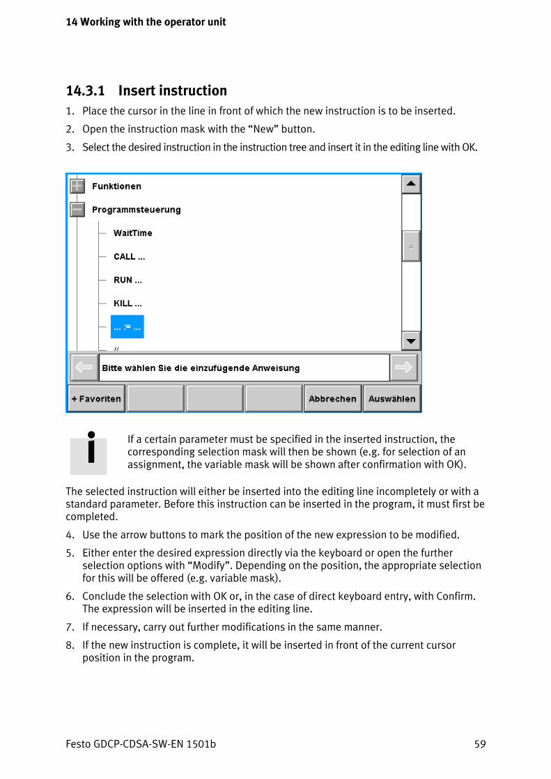
14.3.1 Insert instruction 1. Place the cursor in the line in front of which the new instruction is to be inserted.
2. Open the instruction mask with the “New” button.
3. Select the desired instruction in the instruction tree and insert it in the editing line with OK.
If a certain parameter must be specified in the inserted instruction, the corresponding selection mask will then be shown (e.g. for selection of an assignment, the variable mask will be shown after confirmation with OK).
The selected instruction will either be inserted into the editing line incompletely or with a standard parameter. Before this instruction can be inserted in the program, it must first be completed.
4. Use the arrow buttons to mark the position of the new expression to be modified.
5. Either enter the desired expression directly via the keyboard or open the further selection options with “Modify”. Depending on the position, the appropriate selection for this will be offered (e.g. variable mask).
6. Conclude the selection with OK or, in the case of direct keyboard entry, with Confirm. The expression will be inserted in the editing line.
7. If necessary, carry out further modifications in the same manner.
8. If the new instruction is complete, it will be inserted in front of the current cursor position in the program.
Festo GDCP-CDSA-SW-EN 1501b 59

14 Working with the operator unit
14.3.2 Changing parameters 1. Select the instruction.
2. Switch to the editing mode with the “Modify” button.
The parameter mask will be opened and the selected instruction shown in the editing line.
3. Modify the parameter with one of the following methods:
− Direct value input: Click on the value and enter the value directly in the entry panel which appears.
− “Value” button: When this button is pressed, an entry panel is opened for direct entry of the value. This method is used if a ComboBox for selecting the variable is shown in the “Value” field, but an INT value is to be specified.
− “Variable” menu: A variable can be inserted in the current instruction here (either with select, new or keyboard).
4. When the parameters have been adapted, close the modification with OK.
The parameter has been modified.
14.3.3 Modifying an expression in a program instruction 1. Select expression
2. Switch to the editing mode with the “Modify” button.
The editing line will be opened and the selected instruction shown.
3. Use the arrow buttons to mark the part of the expression to be modified in the editing line.
4. Modify the marked part with the appropriate menu entries.
5. Conclude the modification with OK
The expression has been changed.
14.4 Teach/modify parameter values Teaching or modifying parameter values can take place either directly by entry or by modification of the variable values with the jog buttons.
The sequence described in the following represents only a sample procedure. If necessary, the sequence can be adapted to the individual requirements.
1. Select the desired macro or program in the program window.
2. Switch to the individual step mode with Step/Cont.
3. Using the Start button, carry out the program in individual steps, up to the positioning command to be adjusted.
60 Festo GDCP-CDSA-SW-EN 1501b

14 Working with the operator unit
Direct entry
1. Open the parameter mask with Modify.
2. Enter the new values in the Values table column in the parameter mask. The values entered will be accepted immediately.
3. Close the parameter mask with OK.
With jog buttons
1. Correct the position of the robot with the jog buttons.
2. Open the parameter mask with Modify.
3. Accept the new position values in the parameter mask with the Teach button and close the parameter mask with OK.
14.5 Messages All the messages which have occurred will be shown in the message mask and can be acknowledged here.
The last message is displayed in the status line. The message classes for this display form can be configured. Usually, messages which draw attention to a problem in the system or in the process are shown in this manner.
14.5.1 Acknowledging the message in the message mask 1. Open message mask.
2. Select message.
3. Confirm the selected message with Acknowledge.
All the messages can be acknowledged with “Acknowledge all”. For security reasons, a confirming dialogue will be shown before final acknowledgement is carried out.
Festo GDCP-CDSA-SW-EN 1501b 61

Index
Index
A
Acknowledge ....................................... 61
C
Connection status ................................ 21 Coordinate system ............................... 29
D
Default Gateway ............................ 15, 17 Display setup....................................... 15
E
Editing line .......................................... 36 Execution mask ................................... 56
H
Host IP ................................................. 17
I
I/O monitor mask ................................ 52 Instruction mask .................................. 38 IP-Address ..................................... 15, 17
K
KBUS ................................................... 52 Kinematics ........................................... 21
L
Label list .............................................. 41 Login dialogue ..................................... 45
M
Message classes .................................. 24 Message log ........................................ 24 Message status ................................... 21 Message statuses ................................ 24 Messages ...................................... 24, 61 Module status ..................................... 53
N
Network setup .................................... 15
O
Operating mode .................................. 21 Operator dialogue ............................... 41 Override .............................................. 21
P
Parameter mask .................................. 39 Program mask ..................................... 34 Program status ................................... 21 Project mask ....................................... 34
R
Reference points ................................. 17 Report memory ................................... 27 Robot status ....................................... 21
S
Setup mask ......................................... 43 Setup menu ........................................ 15 Subnet Mask ................................. 15, 17
T
Text editor mask ................................. 42 Touch screen calibration ..................... 17
U
User levels .......................................... 21 User management ............................... 46 User profile ......................................... 48
V
Variable mask ..................................... 37 Variables ............................................. 49
62 Festo GDCP-CDSA-SW-EN 1501b


Copyright:
Festo AG & Co. KG Postfach D-73726 Esslingen, Germany Phone: +49 711 347 0 Fax: +49 711 347 2144 E-mail: [email protected]
The reproduction, distribution or sale of this document or communication of its contents to others without express authorisation is prohibited. Offenders will be held liable for damages. All rights reserved in the event that a patent, utility model or design patent is registered.
Internet: www.festo.com Original: de Version: 1501b


