OPERATOR’S MANUAL This Operator’s Manual MUST BE READ prior to operating your Telescoping Material Handling . DIGGER DERRICK PRINTED IN THE USA 463280 03/2007 TEREX TELELECT Terex Telelect Digger Derrick Telescoping Material Handling Digger Derrick
Transcript
OPERATOR’S MANUALThis Operator’s Manual MUST BE READ prior to operating your
OWNERS, USERS AND OPERATORSThank you for choosing TEREX TELELECT equipment for your application. User safety is our number one priority and this is best achieved by our joint efforts.
As equipment users and operators, you make a major contribution to safety if you:
1. Comply with OSHA, federal, state, ANSI, local and company regulations.
2. Read, understand and follow the instructions in this manual and other manuals supplied with this vehicle.
3. Only allow trained operators, directed by informed and knowledgeable supervision, to run the unit.
If there is anything in this manual that is not clear or you believe should be added, please send your comments to:
Manager of PublicationsTEREX TELELECT, INC.500 Oakwood RoadWatertown, South Dakota 57201
You may also contact us by phone at: (605) 882-4000
This manual contains important information on the safe use of your TEREX TELELECT equipment. Your failure to read, understand and follow all safety rules, warnings and instructions will unnecessarily expose you and others to dangerous situations. For your safety and the safety of those around you, you must operate your TEREX TELELECT equipment as instructed in this manual.
This Symbol means your safety is involved! - Read, understand and follow all danger, warning and caution decals and instructions on your Digger Derrick and in this manual.
-IDigger Derr ick Terex Tele lect 463280 - 3/07
DIGGER DERRICK
INT
RO
DU
CT
ION
Table of Contents
The operator is the single most important factor for safety when using any piece of equipment. Learn to operate your TEREX TELELECT equipment in a safe manner.
To help you recognize important safety information, we have identified warnings and instructions that directly impact on safety.
Danger: Indicates an imminently hazardous situation, which if not avoided, will result in death or serious injury.
Warning: Indicates a potentially hazardous situation, which if not avoided, could result in death or serious injury.
Caution: Indicates a potentially hazardous situation, which if not avoided, may result in minor or moderate injury.
Caution: Used without the safety alert symbol indicates a situation, which if not avoided, may result in property damage.
NOTE: The best method to protect yourself and others from injury or death is to use common sense. If you are unsure of any operation, do not continue until you are satisfied that it is safe to proceed.
1. Study all safety messages. Remember and apply them on the job.
2. Modifications to this TEREX TELELECT equipment from the original design specifications without written permission from TEREX TELELECT are strictly forbidden. A modification may compromise the safety of the TEREX TELELECT equipment, subjecting users to serious injury or death. Any such modification will void any remaining warranty.
3. TEREX TELELECT reserves the right to change, improve, modify or expand features of its equipment at any time. Specifications, model or equipment are subject to change without notice and without incurring any obligations to change, improve, modify or expand features of previously delivered equipment.
4. Comply with manufacturer’s instructions and requirements of current OSHA regulations and ANSI standards.
DANGER
WARNING
CAUTION
CAUTION
In addition to maintenance and operating instructions in this manual, the operator must read and understand all the instructions in the following safety guidelines.
1. The use of this Digger Derrick is subject to certain potential dangers that cannot be protected against by mechanical means. Only the exercise of intelligence, care, and common sense can eliminate these dangers. It is essential to have competent, careful operators who are physically and mentally fit, and thoroughly trained in the safe operation of this Digger Derrick. Learn, understand and practice safe use of all equipment and controls - before operating this Digger Derrick.
2. Never exceed the rated load capacity. Know the total weight of the object(s) to be handled. Stay within the limits shown on the load capacity chart.
3. When operating this Digger Derrick, if you become aware of any dangerous condition or hear any unusual noises such as grinding, cranking or grating sounds, STOP in position. DO NOT move or operate the Digger Derrick until the problem has been diagnosed and resolved.
4. Do not operate this Digger Derrick if any interlock or safety device is malfunctioning.
5. Do not bypass or remove any interlock or safety device.
6. Keep the vehicle free of obstructions that may interfere with the controls or personnel who may have to operate them in an emergency.
7. Do not operate if Digger Derrick is not functioning properly, or has leaks, get repaired before further use.
8. Perform all scheduled maintenance required.
9. Be sure all personnel know the proper procedure to follow in case of an emergency.
10. Do not operate the Digger Derrick in an electrical storm.
11. Never operate the Digger Derrick control while standing on the ground. Always operate controls while standing on the vehicle.
12. Hydraulic oil is flammable. A hydraulic leak may create a mist of oil, which is conductive and explosive.
1. Survey the conditions of the work area. Identify situations such as soft ground, ditches, drop offs, holes, debris, overhead obstructions, electrical conductors and underground utilities.
2. Plan the job (tailgate session) and clear the area of bystanders.
3. The vehicle must be securely parked, set parking brakes and chock wheels.
4. Stabilize the vehicle before any operation is performed.
5. Do not lower outriggers unless you can see that all ground personnel and bystanders are clear of the outrigger path of movement and its ground contact point. Lower all outriggers onto solid footing.
6. Do not place outriggers on ice as slippage may occur regardless of solid footing. Operation on snow or slippery surfaces requires extra care during set up to ensure Digger Derrick and vehicle have sufficient traction to prevent sliding.
7. The Digger Derrick has been stability tested per ANSI A10.31. The lift capacity shown on the load chart must be reduced if vehicle is not level.
8. The Digger Derrick when used for lifting personal in attached platform has been tested per ANSI A92.2 and may be operated on firm, flat, non-level surfaces up to a 5 degree slope.
9. Ground and/or barricade the vehicle per OSHA and your company rules.
10. Perform controls inspection before beginning operation. Do not operate with malfunctioning controls.
11. Inspect winch line for damage and hook for safety latch and damage.
12. Barricade or cover any overhead electrical lines that may be a potential contact during operation.
13. Inspect and maintain personal protective equipment.
14. Perform maintenance as specified in the Maintenance Guidelines.
BEFORE OPERATION
- IV463280 - 3/07 Terex Tele lect Digger Derr ick
DIGGER DERRICK
SA
FE
TY
GU
IDE
LIN
ES
Table of Contents
BOOM FUNCTIONS1. Never operate the Digger Derrick unless you know the location, function, and operation of all the
controls, including emergency and accessory operation.
2. Avoid abrupt starts, stops and reversal of direction. Operate all controls slowly for smooth motion.
3. Keep hands off all moving parts to avoid injury.
4. Do not place booms in the open traffic lanes, stop traffic or barricade lanes to divert traffic from area.
5. Do not allow ground personnel to stand or walk under a suspended load.
6. Never operate controls while standing on the ground.
7. If the vehicle is setup on a slope, use extreme caution. Stability may be affected.
8. Do not allow ground personnel to be in contact with the vehicle or attached apparatus.
9. Do not pull poles using the winch, extension or outriggers, use a pole puller. Do not attempt to lift any items imbedded in the ground, or frozen down.
10. Remain at the controls at all times with a suspended load on the winch line, or personnel in the platform if not equipped with upper controls.
11. Do not exceed the capacities (as listed on the load capacity chart) for boom extensions, angles, boom relation to vehicle and winch line capacity.
12. Do not allow rope to contact energized power lines. Do not rely on the rope being non-conductive.
13. Keep the winch rope clean and dry.
14. Inspect the winch rope daily. Do not operate with a damaged or frayed rope.
15. Use a sling. Do not use the winch rope as a sling.
16. Use only hooks with a safety latch.
17. Use only approved hot line tools for lifting energized conductors. Clean and inspect all fiberglass on the conductor lifter before use. Dirty or damaged fiberglass may be conductive.
DIGGING1. Never dig until all the underground utilities (such as, electrical lines, gas lines and other lines) have been
identified and marked. Call your local “Call before you Dig” hotline or the national number (888) 258-0808 for assistance.
2. Before lowering the digger/auger, clear the area of all ground personnel.
3. Never corkscrew the auger; the force exerted can exceed the load capacity.
4. Before storing the digger/auger, inspect the roll up cable for damage.
5. Before storing the digger/auger, clear the area of all ground personnel.
DURING OPERATION
-VDigger Derr ick Terex Tele lect 463280 - 3/07
DIGGER DERRICK
SA
FE
TY
GU
IDE
LIN
ES
Table of Contents
OPERATION WITH PERSONNEL PLATFORM ATTACHED1. Never operate from the platform with malfunctioning controls. Perform platform and lower controls
inspection; see DAILY INSPECTION in the MAINTENANCE SECTION of this manual.
2. Never operate from the platform unless you know the location, function, and operation of all the controls at the platform.
3. Operator(s) must wear an OSHA approved fall protection system with the lanyard attached to anchor provided.
4. Wear personal protective equipment such as: Insulated hard hat, rubber gloves with leather protectors, and rubber sleeves. Hearing and eye protection, proper boots and suitable clothing may also be required.
5. Do not allow boom, extended boom, platform, or any part of the Digger Derrick to contact fixed objects.
6. Do not use the platform for lifting material. The platform was designed for lifting personnel only.
7. Do not tie off to an adjacent structure, pole, or other equipment.
8. Never exceed rated capacity of platform.
9. Do not pass tools, equipment, or other objects between the occupant of the platform and other personnel on poles or other platforms.
10. Do not sit or climb onto edge of platform or use planks, ladders, or other devices for a work position. Always stand with both feet on floor of the platform.
11. Do not wear climbers while in the platform.
12. Do not allow ground personnel under the platform work area.
13. Do not operate with platform leveling device (such as the platform brake) malfunctioning.
14. Do not move the vehicle with personnel in the platform.
15. Do not leave the platform to build trestles between the platform and another support work location. Avoid careless handling of tools and equipment while aloft. Use a tool tray to help prevent dropping items. Keep ground personnel away from the area directly under the work point unless it is absolutely necessary and caution them that it is necessary to be constantly on the alert for possible falling items.
16. If, when operating the Digger Derrick, you become aware of any dangerous conditions, unusual operation, or hear any unusual noise, such as grinding, cracking, or grating sounds-STOP-in position. Do not move the boom or platform until the problem has been diagnosed and resolved with your safety in mind. No matter how long it my take to get help, waiting is better than a serious or fatal accident.
17. When working from the platform, on structures that contain energized lines or equipment the Digger Derrick must be equipped with top controls per ANSI A10.31.
-VI463280 - 3/07 Terex Tele lect Digger Derr ick
DIGGER DERRICK
SA
FE
TY
GU
IDE
LIN
ES
Table of Contents
ELECTRICITY OBEYS NO LAW, BUT ITS OWN.1. Electricity is an ever-present danger when using a Digger Derrick and working from a platform. Follow all
OSHA, ANSI, state, federal and company rules and regulations when working on or near energized power lines.
2. Always maintain proper clearance from energized power lines. This Digger Derrick cannot protect you from phase-to-phase or phase-to-ground contact, which occurs above the insulating boom section when operating form the platform:
• Allow for sag, sway or rocking.
• If any part of boom-tip, contacts an energized conductor, the entire boom-tip, including the control handle(s), must be considered energized.
• If any part of the boom-tip, contacts a grounded object the entire boom-tip including the control handle(s) must be considered grounded.
3. The booms and boom operators in the personnel platform must be properly insulated from contacts with electrical conductors; including neutrals or ground lines, poles, cross arms and guy wires. Utilize proper insulation such as line covers, rubber gloves with leather protectors, insulated rubber sleeves, insulated hard hats, hot line tools and eye protection.
4. Never place booms, platforms or personnel between energized conductors.
5. Digger/auger must be in the stored position when personnel are in the platform.
6. Never operate the Digger Derrick or personnel platform in an electrical environment if the fiberglass components are damaged, contaminated by moisture or dirt or otherwise improperly maintained. At a minimum, a daily inspection and an annual dielectric testing of all fiberglass components is absolutely necessary to maintain the integrity of the insulation.
7. Never allow ground personnel to come in contact with the Digger Derrick, vehicle or vehicle attachments while in operation near energized power lines.
8. When working on or near energized power lines or equipment, the vehicle must be grounded and/or barricaded and considered as energized.
9. Never rely on the fiberglass platform insulation when in the platform. It may contain small unseen cracks that will allow an electrical path into the platform. Always use a platform liner.
10. Never touch the controls or boom tip area when in the platform without proper protection (rubber gloves), while holding any conductors, neutrals, grounds or other structures.
11. All tools, accessories and other objects must be contained within the platform when working on or near energized power lines.
12. Fiberglass third section shall be fully extended when using personnel platform on or near energized power lines.
13. Ground personnel must wear rubber gloves if they will contact load line, load, auger, or screw anchor attachments while boom is in area of electrical wires.
14. The winch line must be considered conductive.
ELECTRICAL DANGERS
-VIIDigger Derr ick Terex Tele lect 463280 - 3/07
DIGGER DERRICK
SA
FE
TY
GU
IDE
LIN
ES
Table of Contents
1. When working from the platform, only use hydraulic tools equipped with orange hoses marked NONCONDUCTIVE. The hoses must be kept clean and dry.
2. All accessories must be inspected, maintained and operated with the same care and safety rules that apply to Digger Derricks.
3. Tools selected for use with the Digger Derrick must be of the open center type and operate at 2000 PSI (140 kg/cm2) and flow input shall not exceed the maximum tool rating.
If the boom has been lowered by using counterbalance/holding valves, readjust to proper setting and tighten jam nut. Never operate from the platform without first recharging the cylinder with hydraulic oil.
1. Never travel with personnel in the platform or at the control locations.
2. Never travel with the boom(s) raised.
3. Store boom(s) properly in the boom rest with all boom sections fully retracted. If fiberglass boom is not fully retracted, the fiberglass may craze, shatter or eventually buckle.
4. Keep all tools or other items properly stored on the vehicle while traveling. Otherwise, they may fall onto roadway.
5. Fully retract the outriggers. Store the outrigger pads and wheel chocks.
6. Disengage the power take off. If left engaged, the pump will be damaged.
7. Follow the vehicle manufacturer's instructions for operating the vehicle.
8. Remove and store personnel platform for road travel.
1. Only authorized and skilled personnel with complete knowledge of this Digger Derrick shall be allowed to perform maintenance on this Digger Derrick.
2. Never drill holes in the platform.
3. Replace all illegible decals.
4. Do not alter the insulated portion of this Digger Derrick in any way could reduce its insulating value.
5. Do not search for hydraulic leaks with your hands or any other part of your body.
6. Use orange hose marked NONCONDUCTIVE at the boom tip and areas that bridge the insulation gap.
7. All hoses must meet or exceed the working pressure as stated in the maintenance manual.
8. Do not use replacement components that are not equal to the original components.
9. Before doing any work on the hydraulic system, secure the booms and outriggers. Release any hydraulic pressure before attempting repairs or disassembly of hoses, valves, cylinders or any other hydraulic components.
10. Fuel or oil spill may require notification or appropriate Federal, State, or Local officials.
11. Do not operate the Digger Derrick after adjustments or repairs until all guards have been reinstalled, trapped air removed from the hydraulic system, safety devices reactivated, and maintenance equipment removed.
12. The subframe, outriggers and mounting the vehicle must be inspected following the frequent and periodic inspection intervals for fastener tightness, damaged components and weld inspections.
13. Inspect, maintain, and operate the vehicle following the vehicle manufacturer’s guidelines.
MAINTENANCE
-IXDigger Derr ick Terex Tele lect 463280 - 3/07
DIGGER DERRICK
SA
FE
TY
RE
LA
TE
D D
EC
AL
S
Table of Contents
SAFETY RELATED DECALS
If any of these items are illegible or missing, replace them immediately.
NOTE: * Use decals 419265 and 419272 when all booms are steel (not insulated) or have not been dielectrically tested.
Operating this equipment without all safety and control decals in place can be hazardous.
ITEM # DECAL QTY PART #1. ELECTROCUTION HAZARD - ENERGIZED CONTROLS 1 4010662. READ CAREFULLY 1 4145903. ELECTROCUTION HAZARD - INADEQUATE CLEARANCE 1 4192634. FALLING FROM PLATFORM 1 4192645. * ELECTROCUTION HAZARD - NON - INSULATED 1 4192656. UNTRAINED OPERATOR 3 4192677. OUTRIGGER - CRUSHING - DO NOT OPERATE 2 4192688. OUTRIGGER - CRUSHING - STAND CLEAR 4 4192699. CONDUCTIVE HOSE 1 41927010. ELECTROCUTION HAZARD - KEEP CLEAR 3 41927111. * ELECTROCUTION HAZARD - NOT INSULATED 2 41927212. FAILURE TO OBEY THE FOLLOWING 2 41927313. FAILURE TO OBEY THE FOLLOWING 3 41927414. FREE SWINGING AUGER 2 41927515. TWO - BLOCKING 3 41927616. ELECTROCUTION AND EXPLOSION HAZARD 2 41927717. ELECTROCUTION HAZARD 2 41999118. LEVEL INDICATOR 2 47225619. WARNING - ANSI 1 48589420. ESCAPING FLUID UNDER PRESSURE 1 H23877
1,6,11,12,13,14,15,16,17,19,20
2,3,4,5,6,9,13,15
7,18
8 810
-X463280 - 3/07 Terex Tele lect Digger Derr ick
DIGGER DERRICK
SA
FE
TY
RE
LA
TE
D D
EC
AL
S
Table of Contents
1. 2.
3.
Will result if control handles become electrically charged from boom contact with energized conductors and the operator is standing on the ground.
Operate controls from operators platform or while on vehicle only.
For stationary operation, vehicle must be securelyparked, driveline disengaged, and Digger Derrickproperly stabilized prior to operation.To avoid tip-over, all outriggers must be properlyextended on a solid level surface.Operate all controls slowly and smoothly andmake sure controls are returned to neutralafter desired operation.
Keep load under boom tip. Do not side load boomor drag loads. Avoid free swinging loads.
Never move the vehicle until the booms, auger andoutriggers are in properly stowed postion and secured.
Refer to the operator's manual for completeinstructions. If missing, replace manual.
Never operate the machine with personnel underboom or load.
Keep at least 4 wraps of loadline on winch drum.
on structures with energized lines or components.Top Controls are required when working from platform
The term insulated means separated from other conductive surfaces by a dielectric substance (including air space) offering a high resistance to the passage of current (from OSHA 1926.960).
A. Provides an insulating area between section “D” and earth ground when:
• The winch line (synthetic rope or steel cable) is removed from across the fiberglass boom.
• Upper boom is fully extended.
• Fiberglass section is clean, dry and in properly maintained condition.
B. This area does not provide insulation. This area contains conductive materials; such as the boom structure and cylinders. The operator shall not allow any portion of this area to come in contact with an energized phase, ground conductor or grounded objects. Proper protective devices shall be used on all conductors. Any contact with a ground and a phase or between two phase conductors will create a hazard.
C. This area does not provide insulation. This area contains conductive materials such as cylinders, pins, boom structure, and other metal components. The operator shall not allow any portion of this area to come in contact with an energized phase, ground conductor, or grounded objects. Proper protective devices shall be used on all conductors. Any contact with a ground and a phase or between two phase conductors will create a hazard. The position of the pole claws may affect the insulation gap provided by section A.
D. This area does not provide insulation. This area contains conductive materials; such as control levers, uninsulated platform(s), platform support shaft, boom tip structure and other metal components. These objects must be considered connected. The operator shall not allow any portion of this area to come in contact with an energized phase, ground conductor or grounded objects. Proper protective devices shall be used on all conductors. The operator shall not make contact with any portion of this area when working on or near an energized phase, ground conductor or grounded objects, unless wearing proper protective clothing such as rubber gloves and sleeves rated at the voltage of the lines. Any contact with a ground and a phase or between two-phase conductors will create a hazard. Accidental contact of any portion of area D to an energized conductor will energize the entire area D.
E. This area does not provide insulation. This area contains conductive materials such as cylinders, pins, boom structure, turntable, pedestal and other metal components. The operator shall not allow any portion of this area to come in contact with an energized phase, ground or grounded objects. Proper protective devices shall be used on all conductors. This area is attached to the vehicle and connected trailers, which must be barricaded and/or grounded through an approved ground system when working in the vicinity of energized conductors. Any contact with a phase or between two-phase conductors will create a hazard.
NOTE: A properly maintained platform liner will only provide protection for those portions of the body or materials entirely within the liner and not in contact with any part of area D.
E
EE
B
CA
D
-XIXDigger Derr ick Terex Tele lect 463280 - 3/07
DIGGER DERRICK
WH
AT
IS IN
SU
LA
TE
D A
ND
WH
AT
IS N
OT
INS
UL
AT
ED
Table of Contents
The following apply to insulated units only. If the unit is not equipped with an insulating upper boom the unit does not provide any electrical protection. Refer to the ID plate on the unit to determine if it is considered an insulating unit. If it is insulating it will provide insulation only when the upper boom is fully extended, clean and dry, and maintained properly. Then it will only provide protection from current traveling from the boom tip to the truck and ground through the booms.
The insulated Upper Boom section only prevents current from passing from the boom tip to the Lower Boom through the vehicle to ground. All components above and below the insulating section must be considered conductive. This section only provides protection when the winch line does not span the insulating section, the upper boom is fully extended, and in clean properly maintained condition.
The boom tip is everything past the fiberglass insulating section. All boom tip components are structurally and electrically connected. Contact with any part of the boom tip will energize the entire boom tip including, controls and platform support structure.
You must always cover the line and wear rubber gloves with rubber sleeves, and an approved hard hat when any part of the machine is working in or near energized lines or conductors even when working on a grounded line, neutral line, or ground line.
Death or serious injury to the operator or ground personnel can occur if any part of the Digger Derrick contacts an energized conductor, ground line, grounded line, or other OBJECTS. Proper clearance must be maintained.
Working around electrical power lines is covered by ANSI and OSHA Regulations. To reduce danger to the operator and ground personnel or bystanders on the ground, understand and follow all rules.
The fiberglass upper boom and fiberglass platform, including its components, do not protect the platform operator from injury in case of contact between two energized lines, or between an energized line and a grounded conductor.
Anytime the platform occupant(s) contact two items at different potential with out proper personnel protective equipment, their body may become a path for electric current, and they may be electrocuted. This includes touching the controls, any tools, or items on the boom tip while also contacting a line or ground.
All conductors including grounds and neutral lines are current carrying conductors and must be treated as energized unless properly grounded and tested.
You must read the operators manual thoroughly to fully understand the protection the machine will give you.
The fiberglass Upper Boom, in a well-maintained condition, provides electrical insulation between the boom tip and the vehicle to ground. This fiberglass will not protect the platform operator if any portion of the boom tip or upper control station, including options, is brought into contact with an energized or non-energized conductor and the operator is in contact with a different potential, such as grounded non-energized conductor. This type of contact can energize or ground the controls because all components of the upper control station are interconnected. The fiberglass will not provide protection for the operator in phase to phase contact or a phase to ground wire contact, nor will it protect the vehicle from becoming energized if the steel boom sections are brought into contact with an energized conductor. Serious injury or death could result.
-XX463280 - 3/07 Terex Tele lect Digger Derr ick
DIGGER DERRICK
WH
AT
IS
IN
SU
LA
TE
D A
ND
WH
AT
IS
NO
T IN
SU
LA
TE
D
Table of Contents
The fiberglass Upper Boom and platform liners must be dielectrically tested periodically to insure the insulating properties are being maintained. Do not assume that it is so.
Ground personnel must be warned to stay away from vehicle in case of accidental boom contact between conductor and metallic portion of boom, which will cause serious injury or death.
CAB CONTROL OPERATIONMASTER CONTROLThe master control (A) is located in the cab of the vehicle and has a switch on the dashboard. The switch is used to energize the engine stop/start system and the throttle control options, which may be located in the cab, at the outrigger control location or the lower control location or upper controls, (if equipped). When the light is lit (B), the switch is energizing these systems. If the unit is not equipped with engine stop/start, two-speed throttle or 12V hydraulic power, it will not require a master control. The same switch that activates the PTO may also function as the Master Control.
CAB CONTROLS
1-1Digger Derr ick Terex Tele lect 463280 - 3/07
DIGGER DERRICK
OP
ER
AT
ION
GU
IDE
LIN
ES
Table of Contents
ENGINE STOP/START (OPTIONAL)The engine stop/start (C) is a push button control and is usually mounted on the dashboard of the vehicle. To start the engine press the button and hold in for a moment until the engine starts, then release. To stop, or shut off, the engine, press the button again.
POWER TAKE-OFF (OPTIONAL)The power take-off (PTO) is a gearbox used to transmit power from the vehicle transmission to the hydraulic pump, which provides hydraulic oil for the Aerial Device functions. The power take-off control can be a switch on the dash, for electric control systems, or a “push-pull” knob, (usually mounted on the cab floor) and a red light mounted in the vehicle dashboard. When lit, this red (PTO) dash light indicates the PTO is activated and serves to remind the operator not to drive the vehicle with the PTO engaged.
To engage the power take-off properly, refer to the PTO manufacturer's operating instructions and be sure the manufacturer's operating decals are posted in the cab with the PTO controls.
NOTE: Typical controls are illustrated. Each installation may be unique depending on configuration and options.
CAB CONTROL FUNCTIONS
Be sure the vehicle transmission is in neutral, the brakes are applied and the wheels are chocked before using the engine stop/start.
Driving with the PTO engaged may damage both the pump and the PTO.
Master Power Push “up” to activate remote electrical systems.
Push “down” to deactivate remote electrical systems.
Master Power Light
Red light; when lit indicates master power is activated.
PTO Light Red light; when lit indicates PTO is engaged.
Engine Stop/Start
Push and hold to start engine.
Release when engine starts.
Push and release to stop engine.
Can also be used to stop the Digger Derrick in an emergency.
443377003311OOFFFF
OONN
PPOOWWEERRMMAASSTTEERR
OONNPPOOWWEERRMMAASSTTEERR
443377003322
443399995500PPTTOO
443377003333PPUUSSHH//RREELLEEAASSEE
SSTTOOPP//SSTTAARRTT
EENNGGIINNEE
1-2463280 - 3/07 Terex Tele lect Digger Derr ick
DIGGER DERRICK
OP
ER
AT
ION
GU
IDE
LIN
ES
Table of Contents
OPERATOR CONTROLS AND DESCRIPTIONS
Please contact your TEREX TELELECT Dealer for the proper page to insert for your machine.
This page is to show the Lower control station layout.
1-3Digger Derr ick Terex Tele lect 463280 - 3/07
DIGGER DERRICK
OP
ER
AT
ION
GU
IDE
LIN
ES
Table of Contents
Please contact your TEREX TELELECT Dealer for the proper page to insert for your machine.
This page is to show the Lower control station layout.
1-4463280 - 3/07 Terex Tele lect Digger Derr ick
DIGGER DERRICK
OP
ER
AT
ION
GU
IDE
LIN
ES
Table of Contents
MAIN DIGGER DERRICK CONTROL FUNCTIONSThe control location shown on prior pages is generic. The actual location varies depending on purchaser's requirements and options. Some of the following control functions may not be included in the controls for this Digger Derrick. Refer to the control decals on unit for proper operation.
CONTROL ILLUSTRATION DESCRIPTIONRotation Push lever to rotate boom counterclockwise (CCW).
Booms rotate 360 degrees continuously in either direction.
Pull lever to rotate boom clockwise (CW).
Lift Push lever to lower “DOWN” boom sections.
Booms go up to 80 degrees and down to -20 degrees from the horizontal position.
Pull lever to raise “UP” boom sections.
Intermediate Section (Second)
Push lever to extend “OUT”.
Pull lever to retract “IN”.
1-5Digger Derr ick Terex Tele lect 463280 - 3/07
DIGGER DERRICK
OP
ER
AT
ION
GU
IDE
LIN
ES
Table of Contents
Outer Boom Push lever to extend “OUT”.
Pull lever to retract “IN”.
Digger Push lever to dig and also store auger.
Pull lever to reverse and also unstore auger.
Winch Push lever to lower “DOWN” load.
Pull lever to raise “UP” load.
Pole Plummer
“Claw”
Push lever to close “HOLD” arms and guide pole.
Pull lever to “OPEN” arms and release pole.
1-6463280 - 3/07 Terex Tele lect Digger Derr ick
DIGGER DERRICK
OP
ER
AT
ION
GU
IDE
LIN
ES
Table of Contents
Pole Plummer “Tilt” Push lever to tilt “DOWN”.
Used to keep arms perpendicular to pole.
Raise pole arms before operating the third section. Otherwise, damage to the third section can occur.
Pull lever to tilt “UP”.
Top Controls Push lever to divert control to the boom tip.
When in top controls, lower controls are inoperative.
Pull lever to return to lower controls.
Outrigger Controls Push lever to raise “UP” outrigger.
Generally used when control levers are mounted vertical.
Pull lever to lower “DOWN” outrigger.
Auger Release Used with single control units.
Raise auger by slowly rotating in dig direction until auger is off latch. Push and hold to release auger storage latch and slowly rotate auger in reverse direction. Release when auger clears storage bracket.
Digger Speed Allows operator to shift two-speed diggers from low speed to high speed.
Used with single control units.
Rotate clockwise for “HIGH” speed.
Rotate counterclockwise for “LOW“ speed.
Digger/auger must be stored and unstored in low speed. Can cause serious injury or death.
1-7Digger Derr ick Terex Tele lect 463280 - 3/07
DIGGER DERRICK
OP
ER
AT
ION
GU
IDE
LIN
ES
Table of Contents
Auger Release and Digger Speed
Used on dual control units.
Push lever to the left and hold to release auger storage latch. Release when auger clears storage bracket.
Push lever to the right to shift to high speed. Push lever to the right again to shift back to low speed.
Hydraulic Tools Pull lever into “DETENT” to operate tools.
Push lever back to neutral to disengage tools.
Hydraulic Auger Storage
Push lever to lower auger.
Raise auger by slowly rotating in dig direction until auger is off latch. Push and hold to release auger storage latch and slowly rotate auger in reverse direction. Release when auger clears storage bracket.
Pull lever to store auger.
Pressure Gauge Used to monitor pressure reading on single speed systems (Digger/Winch and Controls)
Pressure Gauge Allows operator to monitor pressure reading of digger/winch and control circuits separately.
Auxiliary Let Down Power
Push and hold to engage auxiliary lowering system.
Used when vehicle engine is not operable.
Do no use to operate Digger Derrick continuously.
Foot Throttle Depress with foot to increase engine RPM.
Release to decrease engine RPM.
Auxiliary Winch Push lever to lower “DOWN” or pay out winch line.
Pull lever to raise “UP” or take up winch line.
Generally used with bed-mounted winches.
Tachometer Used to monitor the engine RPM.
1-8463280 - 3/07 Terex Tele lect Digger Derr ick
DIGGER DERRICK
OP
ER
AT
ION
GU
IDE
LIN
ES
Table of Contents
SINGLE STICK FUNCTIONS
CONTROL ILLUSTRATION DESCRIPTIONRotation Twist lever to the left to rotate boom
counterclockwise.
Twist lever to the right to rotate boom clockwise.
Lift Push lever to lower “down” the boom.
Pull lever to raise “up” the boom.
Intermediate Section “Second”
Tilt lever to the left to retract “in” the boom.
Tilt lever to the right to extend “out” the boom.
ROTATER L
IN OUT
DOWN
UP
BO OM
ROTATER L
DOWN
UP
BO OM
BO OMIN OUT
1-9Digger Derr ick Terex Tele lect 463280 - 3/07
DIGGER DERRICK
OP
ER
AT
ION
GU
IDE
LIN
ES
Table of Contents
CONTROLS BELOW ROTATION
AUXILIARY TOOL CONTROL AND CONNECTIONS
ITEM CONTROL DESCRIPTION1. Outrigger Controls Allows extending and retracting of outriggers.
2. Hydraulic Tools (Optional) Directs oil flow to the tool when connected to the quick couplers.
3. Two-speed Throttle (Optional)
Auxiliary Let Down Power
Two-speed throttle provides two engine speeds, low and high, with engine running. Low speed is engine idle.
Auxiliary let down power provides hydraulic power to lower and stow the Digger Derrick in the event of a prime power source failure.
4. Engine Stop/Start (Optional) Allows operator to stop and start engine.
5. Selector A selector valve that allows operation of boom functions when in the “up" position and operation of the outriggers when in the “down" position.
The Selector will function as an emergency stop by taking oil flow away from the active controls.
6. Hydraulic Tool Couplers Quick couplers for hydraulic tool connection.
The decals are an integral part of this Digger Derrick. If the decals are illegible, they must be replaced.
1-10463280 - 3/07 Terex Tele lect Digger Derr ick
DIGGER DERRICK
OP
ER
AT
ION
GU
IDE
LIN
ES
Table of Contents
CONTROLS BELOW ROTATION FUNCTIONS
NOTE: *Can be included with two-speed throttle circuit. When vehicle engine is disabled, the auxiliary let down power can be activated by the two-speed throttle switch.
NOTE: *Do not operate longer than 30 seconds. Continuous operation will drain battery and/or overheat pump motor.
Outrigger Controls Pull “UP” to raise outrigger.
Push “DOWN” to lower outrigger.
Hydraulic Tools Push “DOWN” to energize tool quick couplers pressure and return.
Pull “UP” to disengage.
Selector Outrigger are operational when the controls is in the neutral position.
Pull “UP” to enable boom functions.
Push “DOWN” to enable outriggers.
Engine Stop/Start Can be used to stop vehicle engine in an emergency.
Push and hold to crank vehicle engine.
Push down to enable outriggers.
Two-speed Throttle Push and release to increase engine RPM to preset high speed.
Push and release to return engine RPM to idle speed.
*Auxiliary Let Down Power
Push and hold to engage auxiliary lowering system.
Used when vehicle engine is not operable.
Do not use to operate Digger Derrick continuously.
1-11Digger Derr ick Terex Tele lect 463280 - 3/07
DIGGER DERRICK
OP
ER
AT
ION
GU
IDE
LIN
ES
Table of Contents
PERSONNEL AND TRAININGAll personnel assigned to an Digger Derrick shall be given an opportunity to become familiar with the operation of the equipment before they operate it on a job. The operator and all other personnel should be familiar with the operating procedures. The operator and personnel shall perform training operations until they attain a safe degree of proficiency.
The operator and ground personnel must know and be familiar with the following:
• The equipment operating procedures
• The location and proper operation of all controls
• The lifting capabilities
• How to read the load capacity chart
• Inspection and field maintenance requirements
• Emergency procedures
Have a tailgate session of what work needs to be done and how.
NOTE: Refer to the load chart for rated capacities, boom angles and load radius.NOTE: Do not exceed load chart capacities.
FAILURE TO OBEY THE FOLLOWINGWILL RESULT IN
For stationary operation, vehicle must be securelyparked, driveline disengaged, and Digger Derrickproperly stabilized prior to operation.To avoid tip-over, all outriggers must be properlyextended on a solid level surface.Operate all controls slowly and smoothly andmake sure controls are returned to neutralafter desired operation.
Keep load under boom tip. Do not side load boomor drag loads. Avoid free swinging loads.
Never move the vehicle until the booms, auger andoutriggers are in properly stowed postion and secured.
Refer to the operator's manual for completeinstructions. If missing, replace manual.
Never operate the machine with personnel underboom or load.
Keep at least 4 wraps of loadline on winch drum.
on structures with energized lines or components.Top Controls are required when working from platform
DEATH OR SERIOUS INJURY
DANGER
419273A
1-12463280 - 3/07 Terex Tele lect Digger Derr ick
DIGGER DERRICK
OP
ER
AT
ION
GU
IDE
LIN
ES
Table of Contents
Learn the operators inspection and field maintenance requirements. Many times simple maintenance procedures can prevent expensive breakdowns. A brief preliminary check of oil levels and operating conditions of the Digger Derrick should be made daily before the unit is put into service.
The operator should also know the brand and grade of oil used in the hydraulic system and where more can be obtained if additional oil is needed.
It takes a desire to learn and a pride of accomplishment on the part of the operator to achieve the proficiency and technique of operation necessary to get the most out of this equipment. The equipment will make the job easier and more enjoyable if a high degree of proficiency is attained.
A WELL TRAINED CREW IS A PRODUCTIVE CREW!
If service is indicated, do not delay. Malfunction of one component can cause serious injury to the operator or to others if not corrected immediately.
The ground crew must be trained to operate the Aerial Device in case of emergency.
1-13Digger Derr ick Terex Tele lect 463280 - 3/07
DIGGER DERRICK
OP
ER
AT
ION
GU
IDE
LIN
ES
Table of Contents
PRE-OPERATIONDAILY PRE-OPERATION CHECKSBefore operating this Digger Derrick perform the frequent and periodic inspections and lubrications as outlined in the maintenance section of this manual and check the following.
1. Fuel gauge to make sure there is sufficient fuel to complete the work to be done.
2. Tires for proper inflation and damage.
3. Vehicle hand brake and/or brake lock for proper operation.
4. Vehicle warning lights for proper operation.
5. Store loose objects properly.
6. Check engine oil and radiator coolant.
7. Check under vehicle for pools of liquid.
Check each of the following items for security, leaks, missing components, damage, evidence of cracks, deterioration, etc.
If a problem is found with any of the following items, notify your supervisor immediately. Do not operate the Digger Derrick until the problem has been diagnosed and resolved.
The operator is authorized to perform only the maintenance items in the maintenance section of this manual. All other maintenance must be performed by a qualified Digger Derrick technician.
DIGGER DERRICK CHECKS
1-14463280 - 3/07 Terex Tele lect Digger Derr ick
DIGGER DERRICK
OP
ER
AT
ION
GU
IDE
LIN
ES
Table of Contents
DIGGER DERRICK CHECKS
NOTE: Some items listed above may not be mounted on this Digger Derrick as they are optional equipment.
NOTE: The lower controls shown on the locator diagram are located on the turntable. The lower controls on this Digger Derrick may be mounted elsewhere.
ITEM DESCRIPTION ITEM DESCRIPTION1. Outriggers 24. Winch Line Sheaves2. Outrigger Cylinders 25. Pole Plummer3. Outrigger Alarms 26. Transferable Pole Plummer Mechanism4. Outrigger Mounting 27. Booms5. Return Line Filter 28. Fiberglass Booms6. Main and Auxiliary Pump 29. Top Controls7. Auger storage Bracket and Mechanism 30. Top Control Extension Mechanism8. Auger Roll Up Cable 31. Platform and Harness9. Auger to Hex Shaft Retention Bolt 32. Platform Step10. Digger to Hex Shaft Coupling 33. Platform Mounting11. Digger Mounting and Transfer Mechanism 34. Platform Brake12. Lower Controls 35. Lubrication (see Lubrication Chart)13. Rotation Gear Box 36. Pressure Setting14. Winch Gear Box 37. Overload Devices15. Rotation Bearing Bolts 38. Cylinder Holding Valves16. Rotation Bearing 39. Hydraulic Plumbing17. Lift Cylinders 40. Electrical Systems18. Lift Cylinder Mounting Pins 41. Operator's Manual19. Boom Pivot Installation 42. Pole Puller20. Throttle Control 43. Jibs and Attachments21. Load capacity charts 44. Digger and Mechanism22. Extension Cylinder Connection 45. Telescoping Tubes23. Winch Line and Hook 46. Subframe and Mounting
1-15Digger Derr ick Terex Tele lect 463280 - 3/07
DIGGER DERRICK
OP
ER
AT
ION
GU
IDE
LIN
ES
Table of Contents
VEHICLE AND BODY CHECKSITEM DESCRIPTION ITEM DESCRIPTION1. Fuel Reservoir 14. Outrigger Pads2. Tires and Wheels 15. Outrigger and Tool Controls3. Engine, Radiator and Cooling System 16. Body Grab Handles4. Battery 17. Body Access Steps5. Steering Mechanism 18. Fire Extinguisher6. Brakes 19. Grounding or Barricade Kit7. Transmission 20. Hydraulic Reservoir8. Trailer Light Socket 21. Wheel Chokes9. Trailer Hitch 22. Boom Rest10. Lighting 23. Personnel Protection Equipment11. Mud Flaps 24. Mirrors12. Strobe Lights 25. Back Up Alarm13. PTO Controls
1-16463280 - 3/07 Terex Tele lect Digger Derr ick
DIGGER DERRICK
OP
ER
AT
ION
GU
IDE
LIN
ES
Table of Contents
JOB SITE SURVEYBefore locating the vehicle in position to work, make a complete survey of the job site. During the survey, some of the items to look for include the following:
1. Ambient conditions including temperature.
2. Consider the slope of the ground:
• Unit is tested on maximum 5 degree ground slope as a personnel lift.
• Lift capacity is reduced if not level for material handling.
3. Determine if the ground is firm enough to support the Digger Derrick. If the ground is not firm enough, use pads under the outriggers and crib as needed to distribute the load.
4. If the vehicle must be parked on a slope, always keep the boom on the uphill side, chock the wheels, and work off the rear of the vehicle.
5. If unit has one set of outriggers, evaluate the tire contact area. All tires and axle suspension springs must be equally loaded prior to setting the outriggers.
6. Look for ditches, drop-offs, holes, and debris.
7. Overhead utility and power lines.
8. If grass or shrubs will be underneath when the vehicle is setup, cover grass or shrubs with dirt to prevent a fire.
9. Underground Utilities, such as sewer and water lines, electrical lines, gas lines, and other lines. If digging is to be done, mark the location of all utilities. Call your local “Call Before You Dig” hotline or the National hotline 888-258-0808 to have all underground utilities marked before digging.
10. Determine the vehicle position needed to accomplish the work safely. If it is not safe to proceed use another method or setup.
OPERATING TEMPERATURE RANGEThe ambient operating temperature range of the unit is given on the ID plate. Operation at the extremes of the temperature range requires extra precautions.
Cold weather operation below 10 degrees F requires:
• The hydraulic system must be filled with hydraulic fluid having a pour point suitable for the temperature.
• The hydraulic system must be properly warmed up:
• Operate the pump at idling speed to allow the oil to warm up gradually. Cold, thick, sluggish oil may not move fast enough and will starve the pump, thus causing severe damage.
• Circulate the oil through the outrigger system by cycling each outrigger several times before setting up for boom operation.
• Circulate the oil through the system by cycling each function from the lower controls before operation from the platform.
• The addition of oil heaters may be required.
• Operate the boom and functions slowly to prevent jerking and shock loads.
• Functions may operate sluggish and not be as responsive, so allow more time and distance when starting and stopping movements.
Hot weather operation above 100 degrees F may require intermittent operation to allow the oil to cool or the addition of oil coolers. Do not exceed an oil temperature of 150 degrees F.
1-17Digger Derr ick Terex Tele lect 463280 - 3/07
DIGGER DERRICK
OP
ER
AT
ION
GU
IDE
LIN
ES
Table of Contents
JOB SITE SETUPUse the following procedure after the vehicle is in position at the work site:
1. Turn on the warning lights.
2. Set the brakes and chock the wheels.
3. Set the signs, warning lights, and barricades in accordance with OSHA, ANSI, state, and company rules and regulations.
4. When work is to be performed on or near power lines, ground and/or barricade vehicle, using an approved grounding cable clamped to a static line or neutral, or use drive or screw type ground rod to ground truck, according to your company policy.
5. Engage the power take-off (PTO) following the directions given with the specific PTO installed on the truck.
6. If equipped, turn on master switch to provide electrical power to electrical powered options.
7. Before operation in cold weather (below 10 degrees Fahrenheit), run the hydraulic system at low engine speed to allow the oil to warm up so it flows properly, to avoid starving the pump and causing damage. Cycle each function; outriggers, booms, digger, pole guide and winch several times with no load before use to circulate warmed oil.
SETTING THE OUTRIGGERSBefore lifting the boom or rotation the Digger Derrick, all outriggers must be lowered firmly to the ground on a surface that can support the load, and kept there until all work is complete and the Digger Derrick is stowed for travel. The stability of the Digger Derrick depends on:
• The gross weight of the vehicle
• Boom position
• Load being lifted
• The slope of the ground in the work area
• If the ground is firm enough to support the load imposed
• The condition of the truck tires, axles, torsion bars, outriggers and outrigger pads or cribbing if used.
All contribute to proper stability, because these conditions are widely variable the operator must exercise good judgment and caution when setting the outriggers before using the Digger Derrick. If the vehicle is not level the capacity of the unit must be reduced from what is shown on the load chart. If used with personnel in the platform the vehicle must be level within 5 degrees.
When lowering the outriggers, use the following procedures:
• Units with one set of outriggers behind the rear axles on rear axle mounts, extend the outriggers until the weight of the vehicle is off the springs. Rear tires must remain on the ground. More outrigger extension is allowed the closer the axle is located to the outrigger.
1-18463280 - 3/07 Terex Tele lect Digger Derr ick
DIGGER DERRICK
OP
ER
AT
ION
GU
IDE
LIN
ES
Table of Contents
• Units with one set of outriggers between the axles on behind-the-cab mounts, set the outriggers firmly on the ground, but do not raise the weight of the vehicle off the springs. Tires must remain on the ground with the truck suspension providing equal support on each side of each axle.
• Do not attempt to correct the ground slope with the outriggers; this unloads the low side tires and suspension. The suspension may not provide enough force for stability.
• After setting the outriggers evaluate the truck position and setup. Determine if the tires are equally supporting the load by looking at the clearance to the fenders, body, or bed and the axle location to the axle stop, (rubber bumper) and overload springs. If one tire is closer to the body and the other tires on the opposite side of the same axle is father away from the body the unit is not set up properly. The spring deflection on each side must be the same or the overload springs or rubber bumper both in contact with their stops. Tires on the low side must be cribbed to equalize the truck suspension load so it can provide the force needed for stability if not equally loaded as parked.
The vehicle may be leveled with the outriggers to provide the best stability for full utilization of the Digger Derrick.
The method of setting the outriggers will vary depending on the number of outriggers and configuration. If the vehicle is equipped with one set of outriggers, the tires and the spring force of the truck axles work with the outriggers to provide stability. The location of the outriggers relative to the truck axles and the pedestal will determine how much the outriggers can be extended.
When lowering the outriggers:
• Determine if the truck is properly parked with brakes applied and wheels chocked.
• Position the outrigger pads and ensure that the surface will support the outrigger force, crib as required.
• Before lowering the outriggers, check the area where the outriggers will extend to ensure no personnel or other objects are in the path. Alert all personnel that the outriggers are being moved or positioned.
LIFTING LOADS WITH THE DIGGER DERRICK
Increasing the distance from the vehicle to the load affects the stability of the vehicle, use caution when lowering a load with the boom.
Do not exceed capacity chart loads for boom length and radius.
1-19Digger Derr ick Terex Tele lect 463280 - 3/07
DIGGER DERRICK
OP
ER
AT
ION
GU
IDE
LIN
ES
Table of Contents
SETTING UP ON A SLOPING SURFACE1. If the vehicle must be set up across a slope, so one side of the vehicle is low; extend the low side
outrigger first and make sure that firm contact is made. If full extension does not make firm contact, it must be blocked up. Always keep the boom on the uphill side.
VEHICLE SETUP ACROSS THE SLOPE2. If the vehicle must be set up with the slope, always keep the boom on the uphill side of the vehicle and
always work off the rear of the vehicle.
VEHICLE SETUP WITH THE SLOPE3. If the vehicle must be set up where an outrigger extends into a ditch or gutter and the full extension does
not make firm contact, it must be blocked up.
4. If the vehicle must be set up so an outrigger would be set on a curb with the vehicle in the street, the outrigger span will be shortened. Reposition the vehicle.
All of the above may affect the stability of the vehicle and restrict the load capacity of the vehicle. Proceed with caution under these conditions.
1-20463280 - 3/07 Terex Tele lect Digger Derr ick
DIGGER DERRICK
OP
ER
AT
ION
GU
IDE
LIN
ES
Table of Contents
SETTING UP ON A SOFT SURFACEThe operator must determine how firm the ground is and if the unit can be safely set up and used. If the ground is too soft to support the outrigger load, the outriggers must be placed on large outrigger pads. Make certain the outrigger pad is centered on the pad.
SETTING UP FOR OPERATION ON SNOW AND ICEOperation on snow and ice adds an additional problem due to the slippery conditions. Normal traction is greatly reduced. Just as you need to maintain traction to walk and drive, it is required to keep Digger Derricks and Aerial Devices in a stable position. Rotating and moving the booms may cause the truck to jerk and move. If the unit is not set up securely the truck can slide on ice and snow while operating. When planning your work remember that driving in snow causes snow dust to be deposited on all surfaces. The outriggers and outrigger pads will get snow covered and slippery. Also, as you put pressure on snow, the snow packs down and turns to ice. The person setting the unit up for operation has the entire responsibility for a stable position. The person on the site is the only one who can evaluate the conditions and terrain.
Proper set up requires:
• Outriggers do not slide on the outrigger pads during use.
• Outrigger pads do not slide on the ground during use.
• Set the parking brakes.
• Chock wheels as required, to prevent movement down hill. Evaluate chock location to prevent the truck pivoting around one chock.
• Set units with one set of outriggers so all tires are on the ground.
• Evaluate the terrain to determine the most flat and level set up position.
• Set up truck so if the truck does move slightly, the result isn’t catastrophic.
• Follow Operators manual for set up instructions. Do not place outriggers on Ice as slippage may occur regardless of solid footing.
To properly set up you may need to:
• Remove snow and ice down to bare ground to prevent sliding and to evaluate the support available. Don’t set outriggers on a manhole cover or the edge of a slope or drop off.
• Move as far as required into the street or road so if the truck does move, the tires and outriggers will not slide into the ditch or other hazards.
• Choose a location for the truck that gives the best stability for the work to be done.
• Come back later, to do the work, if the roads are not cleared sufficiently.
• Use traction aids under the tires and outriggers such as sand and gravel or mats.
• Operate the unit smoothly by “feathering” the controls, not jerking the levers.
1-21Digger Derr ick Terex Tele lect 463280 - 3/07
DIGGER DERRICK
OP
ER
AT
ION
GU
IDE
LIN
ES
Table of Contents
DIGGER DERRICK OPERATION
The following conditions must be followed when using a Digger Derrick near energized lines or equipment:
1. No part of the boom, attachments to the boom, load line, or the load shall be brought into contact with or in proximity to an electrically charged conductor.
2. While operating a Digger Derrick, the operator must not create a connection between the vehicle and ground.
3. Prior to lifting the boom assembly out of the boom rest, all ground personnel must be warned to stay away from the vehicle. Ground personnel must not make contact with the vehicle or any apparatus that is attached to the vehicle until the boom assembly has been returned to the boom rest. This may be accomplished by barricading the vehicle.
4. All electrically charged conductors in proximity to the work area must be properly covered or de-energized.
5. The vehicle must be properly grounded.
6. All company and governmental rules and regulations must be followed.
All boom operations must be smooth. When starting or stopping all motions, avoid jerking by slowly metering the control valves. Control movement speed with the engine throttle. Start and stop all boom movements with a low engine speed to make it easier to “feather” the controls for smooth operation.
When more than one of the controls are engaged at the same time, the component that moves with the least hydraulic pressure requirement takes most of the hydraulic oil output. This control lever should be metered (partly opened) so part of the oil flow is available to drive those components that take more power to move. For example, the second section moves with less power than the lift cylinder, so the second section control valve section must be properly metered to activate the lift cylinder and the second section at the same time.
FEATHERING CONTROL VALVEA hydraulic pressure gauge enables the operator to determine the pressure of the fluid in the hydraulic system. Attention to this gauge permits the operator to know when the maximum allowable pressure is being approached, at which point the relief valve operates.
Violation of any of the following conditions may result in serious injury or death.
The Fiberglass upper boom will only provide electrical protection when fully extended in clean undamaged condition and when the winch line does not cross the insulating section. Partial extension reduces the insulation provided.
When fully retracted no insulation is provided, the entire boom is conductive.
Serious injury or death will result if control handles become electrically charged from boom contact with energized conductors and the operator is standing on the ground. Operate controls from operators platform or while on vehicle only.
1-22463280 - 3/07 Terex Tele lect Digger Derr ick
DIGGER DERRICK
OP
ER
AT
ION
GU
IDE
LIN
ES
Table of Contents
Lift the boom off the boom rest and elevate high enough to clear all body obstructions before rotating.
Always allow extra clearance above and below the booms from any obstacle when lifting a load to allow for this deflection.
Make certain that all personnel are in the clear and that there is sufficient overhead clearance before operating the Digger Derrick.
CLEAR ALL BODY OBSTRUCTIONS BEFORE ROTATING
KEEP HEAVY LOADS AS CLOSE TO GROUND AS POSSIBLE
When lifting loads, the booms deflect a certain amount and when the load is relieved, the booms will return to the normal position.
Before lifting any loads, look at the load capacity chart located at the controls and make sure that the load to be lifted does not exceed the load shown for the desired boom length, elevation, and load radius. Determine that the boom movements needed to set the load in the final location do not exceed the load capacity.
1-23Digger Derr ick Terex Tele lect 463280 - 3/07
DIGGER DERRICK
OP
ER
AT
ION
GU
IDE
LIN
ES
Table of Contents
LOAD CHARTThe load chart at the operator location gives the load capabilities of the Digger Derrick for free hanging vertically suspended load. The allowable load must be evaluated as the boom is moved through its travel from original position to final location. Increasing the extension and reducing the angle reduce the load that can be lifted. The load chart gives allowable loads when the vehicle is level. If not level the capacity is reduced.
The capacity of the unit is determined by five items:
1. The rope strength (shown on the right upper side of the load chart).
2. The boom angle (Angle indicator on side of boom)
3. The boom extension. (consider extended if not fully retracted)
4. Rotational position relative to the truck. (Zone A or B).
5. Jib capacity (if used is shown on separate chart).
The allowable load will be the lowest load permitted by the rope strength, Load Capacity Chart, or Jib Capacity Chart. The Load Capacity Chart only gives the boom capacity, the winch line may have to be multiparted to lift the load shown.
Attempting to lift unknown loads may overload the unit or cause instability. Poles and items imbedded in the ground, attached to the ground or frozen down are unknown weights that will overload the structure and may cause structural damage or overturning.
ANGLE INDICATOR AND LOAD CAPACITY CHART DECAL
Complying with Capacity load chart is very important for safe operation. If missing, illegible or damaged replace immediately. Do not assume capacity is the same as other units. Each Load Capacity Chart is only for the Digger Derrick serial number shown on the chart.
Rope
Capacities
1-24463280 - 3/07 Terex Tele lect Digger Derr ick
DIGGER DERRICK
OP
ER
AT
ION
GU
IDE
LIN
ES
Table of Contents
READING THE LOAD CAPACITY CHARTThe chart is divided into areas depending on the extension of the boom. The areas of the chart are labeled:
• FULLY RETRACTED
• All sections are fully retracted in the stow position.
• 2ND SECTION EXTENDED
• The second section is moved out of the stowed position. The third section and fourth section, if equipped, are fully retracted in the stowed position.
• 3RD SEC. EXT. — 2ND SEC. RET
• The third section is moved out of the stowed position. The second section and fourth section, if equipped, are fully retracted the stowed position.
• 2ND AND 3RD SEC EXTENDED
• Both the second section and the third section are moved out of the fully retracted.
• 4TH SEC. EXTENDED
• If not equipped with a fourth section this block will be blank. If the fourth section is out of the fully retracted, or stowed position, this section of the chart applies. It does not depend on position of Second or third section. Any time the fourth section is not fully retracted this section will give the capacity.
NOTE: A section is considered extended if it is moved out of the stowed or fully retracted position.
Each section in the chart has a column that shows:
• The angle of the lower boom.
• The maximum load radius for that boom angle and extension.
• The maximum sheave height for that boom angle and extension.
• The load capacity in Zone A or over the rear of the truck. (Capacity when operated from upper control or with platform occupied.
• The load capacity in Zone B or over either side of the truck. (Capacity when operated from upper control or with platform occupied.
Determine the angle by looking at the angle indicator on the side of the boom. If the angle falls in between the angles shown on the capacity use the lower capacity. As an example, if the boom angle is at 20 degrees, the 15 degrees values are used. If the boom angle increases to 30 degrees, then the values from the 30 degree line are used. If the boom angle decreases from 20 degrees to 12 degrees, then the values in the 0 degree line are used. The Jib Charts are determined the same way as the Load Capacity Chart.
Determine the Zone by determining where the boom is located relative to the truck. Zone A is over the rear of the truck between the corners of the bed. Zone B is to the sides between the corners of the truck bed.
The right side of the chart lists the Load line strength in the note:
”CAUTION: Multiple part lines are required for loads above XXXX.”.
The XXXX is the load capability of the line originally supplied with the unit. If the line is replaced it must be replaced with a line that has the strength as shown of on the load chart. If the capacity determined by the Load Capacity Chart or the Jib Chart exceeds the value XXXX given on the chart the line must be multi-parted or the load limited to the line capacity.
If an optional jib is used, be sure the load does not exceed the jib capacity chart.
1-25Digger Derr ick Terex Tele lect 463280 - 3/07
DIGGER DERRICK
OP
ER
AT
ION
GU
IDE
LIN
ES
Table of Contents
JIB LOAD CHART
LOAD CHART UPPER CONTROL WINCH CAPACITY WITH JIB ASSEMBLY
LOAD CHART UPPER CONTROL WINCH CAPACITY WITHOUT JIB ASSEMBLY
1-26463280 - 3/07 Terex Tele lect Digger Derr ick
DIGGER DERRICK
OP
ER
AT
ION
GU
IDE
LIN
ES
Table of Contents
LIFTING AND BOOM SECTIONSROTATIONThe rotation system is intended to rotate the rated working load suspended on the load line.
If the vehicle is operated on sloping ground, use extreme caution when rotating toward the low side. The load chart on the unit gives the capacity when properly stabilized on level ground. The capacity is reduced if vehicle is not level.
LIFT CYLINDER CAPACITYThe lift cylinders may be used to determine if an unknown load is within the structural and hydraulic lift capacity of the Digger Derrick. When ever using the lift cylinder capacity to determine the capability of the Digger Derrick, caution must be used. The load may not be able to be moved in all positions around the truck. Because of stability limitations your specific unit may not have the full capacity in all positions around the truck. The lift cylinder hydraulic capabilities at the correct relief setting will only determine if a load is within the structural capability of the Digger Derrick boom. The extension cylinders and winch must only be used when it is known the weight does not exceed the capacity shown on the load chart and the allowable winch line capacity. If the load can be lifted hydraulically with the lift cylinders within the stability range of the truck it can be lifted and positioned with other functions only to a lesser load radius, meaning higher boom angles and/or less extension. Positioning the boom at less angle or increased side reach will overload the unit, and must not be done. Never lower the boom, raise with the winch, or extend unless the load is within the capacity of the boom as shown on the load chart.
The vehicle may not be stable in all positions around the truck with the load the lift cylinders can raise. Zoned load charts (Zone A & B for example) with lower capacities over the sides of the truck indicate the load may cause overturning. The load chart must be consulted at the specific boom position to be sure the lift capacity does not exceed the winch line capacity. If the load chart capacity for the boom position exceeds the winch line capacity the winch line must be multi-parted.
When you consult your Digger Derrick load capacity chart, note that the Digger Derrick lift capacity increases at high boom angles and at shorter distances from the centerline of rotation to the centerline of the load (radius). You must know the weight of load to be lifted and the correct position of the boom so the capacity shown in the load capacity chart is not exceeded
To determine if an unknown weight can be lifted all of the following conditions must be met:
• The load must only be lifted with the lift cylinders.
• The hydraulic pressure must be at the proper setting for the particular model and the hydraulic pressure shown on the pressure gauge must not exceed setting shown on the ID Plate.
• The load shown for the boom angle and extension on the load chart must not exceed the winch line capacity as shown on the right side of the load chart, multi-parting may be required.
• Rotational position of the boom relative to the truck must be in the working zone which shows the maximum load on the load chart.
Do not pull, drag, or jerk while using the winch, digger, or rotation control. This can overload and damage the rotation mechanism, which can result in death or serious injury.
1-27Digger Derr ick Terex Tele lect 463280 - 3/07
DIGGER DERRICK
OP
ER
AT
ION
GU
IDE
LIN
ES
Table of Contents
POSITION THE DIGGER DERRICK TO AVOID DRAGGING THE LOADLifting speeds can be controlled with the engine throttle and by metering the control valve. Slow speeds should be used on all heavy loads or when working in close quarters. For smooth operation, start and stop with low engine speed.
ROTATE BOOM TO THE LOAD TO AVOID SIDE STRAINS
INTERMEDIATE SECTION (SECOND SECTION)The second section extension is used for positioning loads and keeping the digger/auger vertical when digging holes. It can also be used for plumbing poles by extending or retracting.
Use extreme care when extending the second section while handling loads. The vehicle can become unstable if the second section is extended to a larger radius with load.
Do not exceed values shown on the load capacity chart for boom position.
HYDRAULIC UPPER BOOM (FIBERGLASS THIRD SECTION)The fiberglass third section is used to position loads and has provisions for attaching a platform for aerial work. Do not assume the fiberglass has any insulating value when lifting loads.
Do not exceed the winch line capacity, which can result in serious injury or death.
Do not use the winch, lift cylinder, or extension cylinder to lift loads that are in excess of the load capacity chart value for the boom position. This can overload and cause damage to component parts, which can result in serious injury or death.
1-28463280 - 3/07 Terex Tele lect Digger Derr ick
DIGGER DERRICK
OP
ER
AT
ION
GU
IDE
LIN
ES
Table of Contents
TRANSFERABLE POLE BUDDY (OPTIONAL)Use the transferable pole buddy when it is necessary to handle poles with the third section. Pin the transferable pole buddy to the second section so it remains with the second section when the Third section is extended or pin it to the third section so it extends with the third section.
To transfer the pole buddy to the third section, retract the third section fully into the second section. Remove the retaining pin from the second section and place it in the pin boss that retains the pole buddy to the third section.
TRANSFERABLE POLE BUDDY W/POLE PLUMMERWhen used with the pole grabbing winch, the winch line has to be routed as shown below.
WINCH LINE ROUTING POLE GRABBING TRANSFERABLE POLE BUDDY
When pinned on the second section, always raise the pole claws before extending the third section to avoid damage to pole claws. To prevent the pole buddy from sliding down the third section, do not unpin from the second section with the third section extended.
1. Retaining Pin
2. 2ND Section
3. 3RD Section
Route the winch line on any Digger Derrick with a transferable tilt pole plummer and pole grabbing winch as shown in following graphic. At all times, the winch line must be routed from the winch drum over the sheave in the third section.
Failure to route the winch line in this manner will result in damage to winch line and/or serious injury or death.
1. Winch Line
2. Winch Drum
3. Sheave
4. 3RD Section
1-29Digger Derr ick Terex Tele lect 463280 - 3/07
DIGGER DERRICK
OP
ER
AT
ION
GU
IDE
LIN
ES
Table of Contents
WINCHESPOLE GRABBING (BOOM TIP) WINCHSome Digger Derricks are equipped with a pole grabbing winch. This winch is mounted on the outer end of the second boom section and travels in and out with the second section. The third section is provided with a sheave arrangement to accept the winch line from the pole grabbing winch.
POLE GRABBING (BOOM TIP) WINCH
TURNTABLE WINCHSome Digger Derricks are provided with a turntable winch, which is located in the turntable behind the rear of the boom.
TURNTABLE WINCH
When the winch line is attached to the third section, always pay out the winch line when extending the third section to maintain clearance between the boom tip and the winch line hook/load. Contact between the boom tip and the winch line hook/load can cause damage to the boom or break the winch line and/or cause serious injury or death.
When extending either the second section or the third section, always pay out the winch line to maintain clearance between the boom tip and the winch line hook/load. Contact between the boom tip and the winch line hook/load can cause damage to the boom or break the winch line and/or cause serious injury or death.
1-30463280 - 3/07 Terex Tele lect Digger Derr ick
DIGGER DERRICK
OP
ER
AT
ION
GU
IDE
LIN
ES
Table of Contents
WINCH LINERopes used on this Digger Derrick must meet or exceed the following requirements or as noted on the load capacity chart:
• Synthetic rope or rotation resistant wire rope must have a minimum breaking strength of 39,000 pounds and a maximum stretch of 2.8 percent at 7,800 pounds.
• Wire ropes (other than rotation resistant type) must have a minimum breaking strength of 27,300 pounds.
Multiple-part lines are required for loads above 7,410 pounds (safe working load). A two-part line attachment requires a shackle, snatch block, and hardware. A three-part line attachment requires a shackle, snatch block, toggle block, and hardware.
Remember, multiple-part lines do not increase the lifting capacity of the Digger Derrick. They only reduce the load on the winch line and the winch. Do not exceed the capacities indicated on the load capacity chart.
MULTIPLE-PART LINE ATTACHMENTInspect the winch line, hook, and hook latch before lifting any loads (see Maintenance sections).
Do not shock load the winch line. Shock loading is a jerking or snatching of the winch line or a sudden change in tension from a relaxed state or low load to high load. Start and stop the load slowly to avoid shock loading. Do not lift loads that exceed the capacities indicated on the load capacity chart or the safe working load of the winch line.
1. The winch is designed for straight-line pulls. The boom must be placed over the load so the winch line is making a vertical pull. Do not side load, as it can damage the boom mechanism or rope and cause it to break.
2. Four wraps must be maintained on the winch drum during lifting operations.
3. Do not allow ground personnel to ride the winch line or load.
4. If your Digger Derrick is supplied with a jib, do not exceed the jib capacity load chart.
5. Maintain proper clearance between energized conductors and boom tip, winch line, hook, and load.
1. Single
2. Two-Part
3. Three-part
Observe the following five rules on winch lines and loads.
1-31Digger Derr ick Terex Tele lect 463280 - 3/07
DIGGER DERRICK
OP
ER
AT
ION
GU
IDE
LIN
ES
Table of Contents
ELECTROCUTION HAZARD
SYNTHETIC ROPE - The dielectric properties of a synthetic rope are obtained from a new, clean rope. These properties hold true only under ideal conditions. Dirt, grease, moisture, humidity, and other foreign matter will dramatically increase the conductivity of synthetic rope.
WIRE ROPE - Wire rope is 100 percent conductive.
STRINGING THE WINCH LINEProperly attach the winch line to the drum with attachments furnished.
The first layer (wrap) around the winch drum must be put on closely and tightly. The initial winding (load) should be approximately 50 pounds. This prevents subsequent wraps from sliding down between turns when tension is applied.
A down haul weight and hook with a latch should be attached to the free end of the winch line. This allows the winch line to drop easily to meet the reach of the crewman on the ground.
DOWN HAUL WEIGHTWhen winding the winch line onto the drum with no load, make sure it is wound level.
Trapped loops can damage the winch line or cause a load to drop on the next winch pay out operation.
WINCH DRUMS WITH TRAPPED LOOPS
Electrocution Hazard exists when any winch line contacts energized source.
Serious injury or death can result if electrical contact is made with a contaminated synthetic rope or a wire rope.
This type of contact can electrically charge the rope, the load, and the vehicle.
All winch line hooks used shall be equipped with a latch. Winch line hooks without a latch can cause serious injury or death.
Always keep the winch line wound level and tight on the boom winch drum.
1-32463280 - 3/07 Terex Tele lect Digger Derr ick
DIGGER DERRICK
OP
ER
AT
ION
GU
IDE
LIN
ES
Table of Contents
OPERATING THE WINCHThe following instructions outline the proper method of hydraulic winch operation to give safe efficient trouble-free service.
Winch line speed should be controlled by metering the control valve with the winch control lever. Move the winch control lever in the desired direction using a slow smooth movement of the control lever. Abrupt lowering or raising of loads will cause shock loads and sudden changes in truck balance. When lifting heavy loads, use slow winch line speeds.
FEATHERING THE WINCH CONTROL LEVERIncreased engine speeds may be used for paying out or taking up the unloaded winch line or extremely light loads.
Continuous operation of the winch under high speeds and/or heavy loads may cause overheating of the winch gearbox or brake.
The winch is equipped with a brake on “WINCH DOWN”. When lowering loads and stopping the winch line movement, if a continued creeping down of the winch line is observed the brake may need repair or adjustment.
When using the optional wire take-up reel, the wire should be spooled on the take-up reel in the same direction as the winch line is wound on the winch drum. Operate the winch control lever in the “WINCH UP” position.
1-33Digger Derr ick Terex Tele lect 463280 - 3/07
DIGGER DERRICK
OP
ER
AT
ION
GU
IDE
LIN
ES
Table of Contents
DIGGING OPERATIONS
1. Before lowering or storing auger, make certain that all ground personnel are clear and the boom is raised high enough (approximately 45 to 50 degrees) and so the auger clears the vehicle body.
2. Maintain proper clearance from all power lines.
3. Do not stand in auger path.
4. Use low speed only to store and un-store digger. Do not shift speeds with digger in stored position; this will allow auger to free spin. Shift to high speed only when digger is un-stored.
5. A free-swinging auger can cause serious injury or death.
LOWERING THE DIGGER/AUGERTo properly lower the digger, the following steps should be taken to ensure a safe operation:
1. “BEWARE” of overhead lines. Inform your surrounding ground personnel that you are about to un-store the auger.
Raise the boom to approximately 45 to 50 degrees.
Remember, if the digger is a two-speed digger, you must un-store it in “low gear”. You must also store it in “low gear”. Do not shift when digger is stored.
AUGER STORAGE LATCH OPERATION2. Fully retract the second section, raise digger/auger by moving lever in the “DIG” direction to allow latch
to release.
3. Push and hold the auger release valve to open the latch. Release the auger release valve after the auger clears the storage bracket.
4. Continue to lower the digger/auger slowly to vertical position and unsnap cable.
5. When the auger is un-stored, inspect the auger roll-up cable for damage. If any damage is found, replace it.
Observe the following five rules on digging operations.
Intermediate boom section must be fully retracted prior to un-storing digger/auger.
1-34463280 - 3/07 Terex Tele lect Digger Derr ick
DIGGER DERRICK
OP
ER
AT
ION
GU
IDE
LIN
ES
Table of Contents
CHANGING AUGERS1. DO NOT change or remove an auger directly underneath a power line.
2. Lower the outriggers. Make sure the vehicle is stable for boom movements.
3. If the changeover auger is stored on the bed of the vehicle, it must be removed to ground level. Use a sling and the winch for removing auger.
4. When the changeover digger/auger is on the ground, remove the sling and winch line.
5. See lowering procedure.
6. There are two choices of what to do once the auger is un-stored.
a. If you are in an area where you can digger the auger into the ground, dig down about two feet and stop. Remove the auger retaining nut and bolt. Raise boom so the hex shaft is clear of the auger. Use the winch line and a sling to pick up the changeover auger. Attach the sling to the auger above the balance point. Raise auger until it is in an upright position. Guide the auger underneath the hex shaft. Lower hex shaft into auger stem. Install the retaining bolt and nut in the desired hex shaft extension hole. Remove sling.
b. To handle auger(s) when you cannot dig in, wrap a sling around the auger stem above the balance point. Attach winch line and raise the auger slightly so the retaining nut and bolt can be removed. Raise the boom and pay out the winch line. When the hex shaft clears the auger stem, lower auger to the ground. Use the winch line and a sling to pick up the changeover auger. Attach the sling to the auger above the balance point. Raise auger until it is in an upright position, leaving the auger head on the ground. With assistance from ground personnel, align the hex shaft with the auger stem. Lower hex shaft into auger stem. Install the retaining bolt and nuts in the desired hex shaft extension hole. Remove sling.
DIGGING POLE HOLES
After the auger has been lowered, position it on stake location by using the second section extension and rotation movement of the boom to set the point of the auger firmly on the ground. The digger moves in and out with the hydraulic extension when it is in the lowered position and has been latched to the second section.
When starting to dig on inclines, angle the digger/auger to the point where the auger head is perpendicular to the incline. Turn the auger several revolutions before starting a gradual return of the digger to a vertical position.
DIGGING HOLES ON AN INCLINEIf the vehicle is operated on sloping ground, use extreme caution when rotating toward the low side. The load chart on the unit gives the capacity when properly stabilized on level ground. The capacity is reduced if vehicle is not level.
Wrap a sling around the auger above the balance point. DO NOT wrap the winch line around the auger as the sharp flights could damage the winch line.
Remember to “Call before you dig”.
1-35Digger Derr ick Terex Tele lect 463280 - 3/07
DIGGER DERRICK
OP
ER
AT
ION
GU
IDE
LIN
ES
Table of Contents
An alternate method of digging on an incline is to level the digging area with a shovel before setting the auger.
DIGGING HOLES ON AN INCLINE (ALTERNATE METHOD)NOTE: Under normal conditions, the point of the auger is the pilot to properly locate the hole.
Push the digger control to “DIG” position and lower the auger into the ground by slowly lowering the boom. Control the rate of lowering the boom to get maximum penetration but do not stall the digger. When using carbide teeth, always remove down pressure before reversing the auger to avoid damage to the carbide teeth.
Raise the auger periodically and spin off the soil. Soil can be spun off by rotating the auger. In sticky soil conditions, loosen soil with a shovel while rotating auger slowly. Do not bury the top flighting of the auger as soil will compact on top.
SPINNING THE DIRT OFF THE AUGERUnder “heavy” soil conditions, auger tends to corkscrew rather than dig. Regulate the down pressure of the boom to avoid this. Keep auger vertical by metering the second section extension and boom rotation controls.
AVOID DIGGER CORKSCREW
1-36463280 - 3/07 Terex Tele lect Digger Derr ick
DIGGER DERRICK
OP
ER
AT
ION
GU
IDE
LIN
ES
Table of Contents
DIGGING IN ROCKY CONDITIONSDigging in rocky soil requires slow speed to obtain best results and to avoid damage to auger teeth, digger, and equipment from striking heavy stones.
In rocky soil, carefully lower the auger and avoid excessive down pressure. Most rocks are brought up on the auger flighting or pushed out of the way by the auger head.
Judgment dictates whether or not rocks raised to the surface should be pushed aside by the ground personnel. Letting the auger kick out the rocks may result in rock returning to hole. If the auger strikes rocks and stalls, it may be possible to lift the rock out with the boom, keeping the digger “IN GEAR”. If that does not work, decrease down pressure and reverse the digger for a 1/2 revolution before proceeding.
DIGGING IN FROST OR HARD PANWhen digging in frost or hard pan, use carbide auger teeth and point. For digging in these conditions, recommend using a slow speed and maximum down pressure. If auger head is allowed to slide, a tough ice slick may form, which could prevent penetration. If digging is particularly severe, move the second section in and out slightly or rotate the derrick slightly to either side of vertical. This speeds digging by concentrating the down pressure first on one side and then the other.
TILTING AUGER TO APPLY DOWN PRESSURENOTE: Always keep the auger rotating when doing this.
Too much side pressure can bend the auger stem.
1-37Digger Derr ick Terex Tele lect 463280 - 3/07
DIGGER DERRICK
OP
ER
AT
ION
GU
IDE
LIN
ES
Table of Contents
DIGGING DEEP HOLESIf it is necessary to dig holes deeper than 6 or 7 feet, move the auger to a lower attaching hole on the hexagon extension shaft. This shaft is 60-inches long and has several attaching holes that can be used to extend the auger for deep holes or over an embankment. Do not attempt to stow auger in an extended position. Return to shortest length before storing.
DIGGING DEEP HOLES OR OVER EMBANKMENTS WITH THE EXTENSION SHAFT
1-38463280 - 3/07 Terex Tele lect Digger Derr ick
DIGGER DERRICK
OP
ER
AT
ION
GU
IDE
LIN
ES
Table of Contents
DIGGING ANCHOR HOLESAnchor holes can be dug at any angle, but use extreme caution when doing so. To maintain the correct angle, adjust the second section extension or rotate the boom to prevent excessive strain on the derrick when the auger is lowered and raised during the digging and cleaning operation.
Raise the auger one or two feet intermittently during the digging operation. This assists in cleaning out the hole, and a 7-foot deep hole can be dug without completely removing the auger.
It is easier to dig anchor holes as nearly in line with the Digger Derrick as possible. This permits controlling the angle of the auger and lowering the auger into the hole using only the lift cylinder and the second section cylinder.
If it is necessary to dig at any angle to the Digger Derrick, use the lift cylinder, second section, and rotation.
DIGGING ANCHOR HOLES AT AN ANGLE
DIG AS NEARLY IN LINE WITH THE DERRICK AS POSSIBLEAttach the anchor auger to the end of the hexagon extension shaft of the digger. The depth of the anchor hole depends on the distance between the auger head and the digger head. Coordination of the two boom movements, down and in the direction of the anchor hole, must be as nearly perfect as possible.
Use caution when exerting down pressure as well as when pulling the anchor auger from the hole. Keep the auger turning to prevent bending when pulling and while applying pressure at an angle.
Use caution around lines. The anchor and drive attachments are conductive and if the Digger Derrick booms, or anchor drive or anchor touches an energized line the entire vehicle and attachments are energized.
1-39Digger Derr ick Terex Tele lect 463280 - 3/07
DIGGER DERRICK
OP
ER
AT
ION
GU
IDE
LIN
ES
Table of Contents
SETTING SCREW ANCHORSInsert screw anchor into hollow shaft, and secure in position with retainers.
ILLUSTRATION OF SCREW ANCHORThe digger has adequate torque and proper boom control for driving screw anchors at any angle under almost all soil conditions. In stratified soils, the changes in penetration resistance from layer to layer cause changes in torque and down pressure. The operator must compensate for these changes. Inadequate down pressure may result in “churning” the soil, which destroys its holding strength. Careful coordination of digger rotational speed and rate of advance of the boom must be obtained for a low and steady rate of penetration for optimum installation.
Set the screw anchors as nearly in line with the Digger Derrick as possible. This permits controlling the proper angle of screw anchor by using only the lift cylinder and the second section cylinder.
DIGGING IN LINE WITH DIGGER DERRICKTo release screw anchors from hollow auger shaft after it has been set, pull out on the retainer clips and, using boom functions, raise the shaft from the screw anchor.
STORING DIGGER/AUGERTo properly store the digger, do the following steps to ensure a safe operation:
1. Fully retract the second section.
2. Attach the roll-up cable to auger stem.
3. Raise boom to 45 degrees. Inform your ground personnel that you are about to store the digger.
Remember, if the digger is a two-speed digger, you must store it in “low gear”.
4. Move digger control lever to “DIG” position until auger rolls up the side of the bracket and moves into the storage bracket.
5. There is an audible “click” when the latch secures the auger. Allow the auger to settle back on the latch.
The roll-up cable can also be replaced while it is in the stored position.
1. Digger
2. Retainer Clip
3. Retainer
4. Hollow Auger Shaft
5. Screw Anchors
If the auger is rotated after it reaches the top of the bracket, it is possible to break the roll-up cable, which could result in serious injury or death.
1-40463280 - 3/07 Terex Tele lect Digger Derr ick
DIGGER DERRICK
OP
ER
AT
ION
GU
IDE
LIN
ES
Table of Contents
HANDLING AND SETTING POLES
ELECTROCUTION HAZARDS FROM OVERHEAD LINES
ELECTROCUTION HAZARDIf permissible, de-energize the lines and test to verify lines are not energized.
DO NOT set, install or remove poles in, near, or among energized lines without taking the following precautions:
1. Ground the vehicle.
2. Always maintain proper clearance from energized power lines. The Digger Derrick cannot protect you from phase-to-phase or phase-to-ground contact. Allow for sag, sway, or rocking. Boom tip contains conductive materials.
3. Assign a spotter whose only responsibility is to spot the pole and boom for the operator.
4. All personnel must wear suitable insulating gloves, sleeves, and hard hats. Personnel must not allow any non insulated part of their body to contact the pole, vehicle, or other equipment.
5. Pole must be covered with insulating shields and pole cap.
6. Energized lines must be covered with insulating shields.
7. Direct contact with insulated poles and lines must be avoided.
8. Never allow ground personnel to come in contact with the Digger Derrick, vehicle, or vehicle attachments while in operation near energized power lines.
9. While on the vehicle, the operator must not create a connection between the vehicle and ground.
Serious injury or death will result from such contact or if inadequate clearance is not maintained.
ELECTROCUTION HAZARD: When the boom is supporting the pole in or near energized lines, the tamp operator MUST wear suitable insulating gloves, sleeves, and hard hat. The tool hoses may be reinforced with wire braid and will become energized if the vehicle becomes electrically charged. Serious injury or death will result from contact with this equipment or vehicle should it become electrically charged.
Before handling or setting poles, the operator should ensure the pre-operation procedures have been checked, the vehicle is properly positioned, and the outriggers are firmly in place.
1-41Digger Derr ick Terex Tele lect 463280 - 3/07
DIGGER DERRICK
OP
ER
AT
ION
GU
IDE
LIN
ES
Table of Contents
Once the pole hole is dug to the required depth, it is ready to accept the pole. Make sure soil is packed tight at bottom of hole, using a tamper (see Recommended Tamp section).
Before hooking the pole, two things must be determined:
• Weight of the pole
• Proper boom angle required to support the weight of the pole (using the load capacity chart)
Place a sling or butt chain (not the winch line) on the pole above the balance point. The longer the pole, the closer the sling or butt chain must be to the balance point. If the pole is properly hooked before raising the pole, there should be little need to align the gains or cross arms once the pole is positioned.
HANDLING POLE
Before raising the pole, verify the boom is at the proper angle and properly hooked to support the weight of the pole; also make sure the winch line is perpendicular and vertical with the pole. This limits the amount the pole can move when it is being raised off the ground. Raise the pole slowly.
Serious injury or death will result if control handles become electrically charged from boom contact with energized conductors and the operator is standing on or is in contact with the ground. Operate controls from operators platform or while on vehicle only.
1-42463280 - 3/07 Terex Tele lect Digger Derr ick
DIGGER DERRICK
OP
ER
AT
ION
GU
IDE
LIN
ES
Table of Contents
When the pole has been raised to the vertical position, take up on the winch line until the pole is firmly held between the boom tip flanges. If the unit is equipped with a pole plummer, bring the arms around the pole so they can be used as a guide when lowering the pole into the hole. See HYDRAULIC TILT POLE PLUMMER (Optional).
POSITIONING THE POLE INTO THE HOLEWhen the pole is controlled, it can be positioned directly over the hole. Make sure all ground personnel are aware of any pole contact with energized lines and the requirements before contacting pole.
As the pole is being lowered into the hole, a second crew member should assist guiding the pole into the hole. When the pole is being lowered, it may be necessary to retract the boom section to maintain vertical alignment of pole.
If the pole needs to be rotated to align gains or cross arms, slack off slightly on the winch line so the pole can be turned. Have a crew member give directions for plumbing the pole. Meter the controls for boom functions when plumbing the pole. When the pole is properly plumbed, hold it in position with boom while replacing and tamping the soil around the pole.
After the pole is tamped, release the winch line and remove from pole.
1-43Digger Derr ick Terex Tele lect 463280 - 3/07
DIGGER DERRICK
OP
ER
AT
ION
GU
IDE
LIN
ES
Table of Contents
HYDRAULIC TILT POLE PLUMMER (OPTIONAL)Open the tilt pole plummer circular arms to allow the pole, retained by the winch line, to be nested into the winch flanges. Then tilt the pole plummer either forward or backward to align the circular arms perpendicular to the pole. Then close the arms around the pole. With this completed, the pole can be maintained vertical to the pole hole.
HYDRAULIC TILT POLE PLUMMER WITH TURNTABLE WINCH
HYDRAULIC TILT POLE PLUMMER WITH POLE GRABBING WINCH
Use the pole plummer arms as guides only. They should not be clamped tightly to the pole or used to lift any of the pole weight. Use the winch line and winch flanges to lift and retain the pole. When raising or lowering boom during the pole setting operation, adjust the pole plummer arms to a horizontal position. This helps prevent damage to the pole plummer arms.
1-44463280 - 3/07 Terex Tele lect Digger Derr ick
DIGGER DERRICK
OP
ER
AT
ION
GU
IDE
LIN
ES
Table of Contents
HYDRAULIC TILT POLE PLUMMER TRANSFERABLE (OPTIONAL)The same method of operation as the hydraulic tilt pole plummer applies; except it can be transferred from the second boom section to the end of the third section.
TRANSFERABLE TILT POLE PLUMMER WITH TURNTABLE WINCH
TRANSFERABLE TILT POLE PLUMMER WITH POLE GRABBING WINCH
1-45Digger Derr ick Terex Tele lect 463280 - 3/07
DIGGER DERRICK
OP
ER
AT
ION
GU
IDE
LIN
ES
Table of Contents
RECOMMENDED USE OF HYDRAULIC TAMPAfter the pole is inserted and plumbed, recommend one crew member shovels dirt in around the pole and another begins tamping from the bottom of the hole. For even compaction, make sure the dirt is tamped as the hole is filled. This ensures having a uniformly tamped pole, leaving a minimum amount of excess material.
If the tamp is leaned in the direction of travel, it will tend to “walk” itself around the pole.
GRADUALLY FILL THE HOLE WHILE TAMPING
WALKING THE TAMP AROUND THE HOLE
ELECTROCUTION HAZARD: When the boom is supporting the pole in or near energized lines, the tamp operator must wear suitable insulating gloves, sleeves, and hard hat. The tool hoses may be reinforced with wire braid and will become energized if the vehicle becomes electrically charged. Serious injury or death will result from contact with this equipment or vehicle should it become electrically charged.
1-46463280 - 3/07 Terex Tele lect Digger Derr ick
DIGGER DERRICK
OP
ER
AT
ION
GU
IDE
LIN
ES
Table of Contents
RECOMMENDED PROCEDURE FOR REMOVING POLES(ZONE A ONLY)
The load imposed by poles or unknown weights can be estimated by using the lift cylinders if all the precautions are followed to prevent overloading the unit or causing instability. See ”LIFT CYLINDER“ section of this manual for the proper procedure. Never attempt to loosen or lift poles with the boom extension, rotation or winch.
If the lift cylinders cannot raise the weight, a pole puller must be used to loosen the pole from the ground. Once the pole has been loosened with the pole puller cylinder then the lift cylinders can be used to raise the pole carefully. If the lift cylinders will not raise the pole, the pole puller cylinder must be used again as many times as required. Do not use the pole guide to grab the pole, it is only to guide and aid to maintain control. Maintain control of the pole and use caution while lifting items that may be imbedded in the ground, frozen to the ground or fastened to the ground or other heavy objects. A sudden release of the object may cause the boom, load line or load to recoil violently.
The winch and boom on the Digger Derrick must never be used to pull poles or other objects imbedded in the ground. The load imposed is an undetermined force that can damage the equipment and endanger operators and ground personnel, causing serious injury or death.
Maintain control of poles and objects at all times. Sudden changes in loads can cause the object to break, or loosen the rigging, or fall.
1-47Digger Derr ick Terex Tele lect 463280 - 3/07
DIGGER DERRICK
OP
ER
AT
ION
GU
IDE
LIN
ES
Table of Contents
HYDRAULIC POLE PULLER (OPTIONAL)The hydraulic pole puller is a large hydraulic cylinder used for removing a pole or butts.
HYDRAULIC POLE PULLERThe pole puller is equipped with a heavy-duty steel base and a slotted head for attaching a chain loop.
1-48463280 - 3/07 Terex Tele lect Digger Derr ick
DIGGER DERRICK
OP
ER
AT
ION
GU
IDE
LIN
ES
Table of Contents
SETTING UP AND USING THE POLE PULLER1. The steel base of the pole puller must be set on a firm level surface before operation. Shovel out a level
surface if necessary. If the ground is soft, use a broad footpad or cribbing under the pole puller.
RECOMMENDED PLACEMENT OF POLE PULLER
2. Place the pole puller on the side of the pole either toward or away from the boom, so the force exerted does not result in a side pull on the Digger Derrick.
3. Drop the eye of pulling chain on the slotted head of the pole puller ram, loop the chain snugly around the pole, and insert the chain end in the slot on the pole puller ram. Make sure the chain is not kinked or twisted.
RECOMMENDED ATTACHMENT OF POLE PULLERPlace the chain loop square around pole. The eye ring goes over the ears of the pole puller.
4. Attach auxiliary hose from vehicle to the correct coupler on the pole puller. Pull on each hose to make sure they are fully engaged with the coupler to prevent damage to the pole puller.
5. Wrap a sling around the pole above the center of gravity of the pole and attach the winch line hook to the sling and snug up the winch line. Activate the pole puller by slowly operating the control valve.
STAND CLEAR! (Pole puller is capable of developing 40,000 to 60,000 pounds of force.)
6. After each pull is made, take up on the winch line and reposition the boom, if necessary, to maintain control of the pole.
7. Because the pole is tapered, it may be necessary to reposition the chain on the pole to prevent difficulty in removing the chain.
8. If the pole butt is loosened or if it is necessary to retract the pole puller to take a new grip or snug up the winch line, be sure to hold the pole puller upright while retracting. This prevents the pole puller from toppling over and scratching or damaging the cylinder rod.
Do not hook chain and pole puller together using the chain as a choker chain around the pole. Both ends of the chain must be attached to the pole puller ram.
1-49Digger Derr ick Terex Tele lect 463280 - 3/07
DIGGER DERRICK
OP
ER
AT
ION
GU
IDE
LIN
ES
Table of Contents
9. The Digger Derrick should always be used to keep the pole vertical until it is completely removed from the hole and the pole puller is removed.
10. In extreme cases of pole removal, holes may be dug directly along side the pole to loosen the soil and assist the pole puller.
11. DO NOT use the boom to loosen the pole.
LOOSENING DIRT AROUND OLD POLE
1-50463280 - 3/07 Terex Tele lect Digger Derr ick
DIGGER DERRICK
OP
ER
AT
ION
GU
IDE
LIN
ES
Table of Contents
AERIAL OPERATIONA manual or hydraulic fiberglass third section is available. The Digger Derrick may be equipped with single or dual fiberglass personnel platforms with brackets for attaching them to the extension. Controls to operate the equipment from the platform are also available.
LIFT LOCK HANDLESIf a control lever at the upper controls operates a boom function, other then in the single stick, the control will have a lift lock handle.
A spring-loaded lever on each boom function lever locks the levers in a neutral position and prevents accidental actuation. A control lever placard indicates the direction to move the control lever to activate a specific boom movement. To activate a boom movement the handle must be pulled "up" and held, so the control lever can operate the desired boom function. When the handle is released the spring pulls the handle "down" to a neutral position and locks the control lever in that position.
AERIAL PLATFORM OPERATIONBefore using the Digger Derrick for aerial platform operations, the operator must make sure all pre-operation procedures have been followed (refer to DAILY PRE-OPERATION CHECKS). Extreme care must always be exercised when lifting personnel aloft.
The aerial platform operators must have a complete and full understanding of the aerial operations contained in this manual before using the Digger Derrick for aerial platform operations.
AERIAL PLATFORM, BRAKE, AND FALL PROTECTION SYSTEMThe aerial platform is used in conjunction with the manual or hydraulic fiberglass third section. The aerial platform consists of single or dual platforms mounted on the side(s) of the third section and hydraulic operated controls for the Digger Derrick functions.
WORKING ON OR NEAR ENERGIZED CONDUCTORSWhen working on or near energized conductors (either known or suspected), special conditions arise.
While the fiberglass upper boom provides a high degree of electrical insulation between
the platform and the vehicle, there are several things it WILL NOT DO:
• It will not provide phase-to-phase protection.
• It will not provide phase-to-ground protection through static lines or guy wires.
• It will not protect the vehicle from being energized if steel booms contact a low level power source.
1. Aerial Platform
2. Brake
3. Fall Protection System
4. Lanyard Anchor
1-51Digger Derr ick Terex Tele lect 463280 - 3/07
DIGGER DERRICK
OP
ER
AT
ION
GU
IDE
LIN
ES
Table of Contents
The fiberglass boom must be fully extended, kept clean and dry for this type of work.
DANGER LABEL ABOUT OCCUPANTS OF THE PLATFORM
The fiberglass boom and platform liners must be dielectrically tested periodically to ensure that the insulating properties are being maintained. Do not assume that it is so (refer to ANSI A10.31).
Platforms without liners are not certified as an electrical insulating barrier.
If the Digger Derrick has a manual third section, make sure the pin that locks the third section in the extended position is installed. If not locked, the third section will retract and can result in serious injury or death.
When using the Digger Derrick as an insulated aerial platform, the Digger Derrick must have a fiberglass section and it shall be fully extended to provide maximum insulation.
Winch Line shall be removed from boom tip and stored on winch drum.
Violation of any of the following conditions can result in serious injury or death.
1-52463280 - 3/07 Terex Tele lect Digger Derr ick
DIGGER DERRICK
OP
ER
AT
ION
GU
IDE
LIN
ES
Table of Contents
When using the Digger Derrick as an insulated aerial platform, the following conditions must be maintained:
1. The fiberglass third section has been dielectrically tested for excessive leakage in accordance with ANSI A10.31, and must be fully extended to provide maximum insulation.
2. The fiberglass third section must be dry, clean, and free of damage.
3. The winch line should be removed from the boom tip and stored on the winch drum.
4. The fiberglass third section shall not be brought into contact with or in proximity to an electrically charged conductor.
5. The main boom and second section or the components mounted on them shall not be brought in to contact with or in proximity to an electrically charged conductor.
6. While on the vehicle, the operator must not create a connection between the vehicle and ground.
7. All ground personnel must be warned to stay away from the vehicle prior to lifting the boom assembly out of the boom rest. Ground personnel must not make contact with the vehicle or any apparatus that is attached to the vehicle until the boom assembly has been returned to the boom rest. This may be accomplished by barricading the vehicle.
8. All electrically charged conductors in proximity to the work area must be properly covered or de-energized.
9. The vehicle must be properly grounded.
10. All company and governmental rules and regulations must be followed.
11. All personnel must wear suitable insulating gloves, sleeves, and hard hats.
12. Operators in the platform must wear an OSHA approved fall protection system with the lanyard attached to the anchor provided.
AERIAL PLATFORMS (OPTIONAL)A slow and smooth operation of the Digger Derrick is particularly important when personnel platforms are attached to the boom tip. Personnel in the platform must utilize a fall protection system and attach lanyard to the platform anchor provided before operating equipment. In addition, make sure the brake is disengaged before operating controls. Engage brake only when personnel are in proper working position.
When the aerial platform is used with the optional winch control, it provides no insulation value because the winch line crosses the insulating section.
Electrical contact can cause serious injury or death.
When working from the platform on energized lines or structures containing energized lines or equipment the top controls are required.
Never engage the platform brake when booms are in motion.
1-53Digger Derr ick Terex Tele lect 463280 - 3/07
DIGGER DERRICK
OP
ER
AT
ION
GU
IDE
LIN
ES
Table of Contents
AERIAL PLATFORM AND BRACKET INSTALLATION1. To install platform on the boom tip, use the following procedures:
a. Install sleeve (4) on platform mounting shaft (7). Insert bolt (2) through sleeve (4) and platform mounting shaft (7). Secure with nut and lock washer.
b. Insert the platform mounting shaft (7) into the boom tip. Align ear (5) with stud (3).
c. When ear (5) is completely engaged with stud (3), install Klik pin (1).
RIGHT-HAND PLATFORM MOUNTINGNOTE: For left-hand platform installation with left-hand controls, use same procedure as above.
This installation will require a different sleeve.2. To install dual platforms, use the following procedures:
a. Install sleeves (5) and (4) on platform mounting shaft (6). Install bolts (2) through sleeves (5) and (4) and platform mounting shaft (6). Secure with nut (2) and lock washer.
b. Insert the platform mounting shaft (6) into boom tip. Align ear (8) with stud (3). When ear (8) is completely engaged with stud (3), install Klik pin (1).
c. Install sleeve (4) on platform mounting shaft (9). Install bolt (2. through sleeve (4) and platform mounting shaft (9). Secure with nut (2) and lock washer.
d. Insert the platform mounting shaft (9) into boom tip. Align ear (8) with stud (3). When ear (8) is completely engaged with stud (3), install Klik pin (1).
DUAL PLATFORM MOUNTING
1. Klik Pin
2. Bolt, Lock washer, and Nut
3. Stud
4. Sleeve
5. Ear
6. Platform and Brake Assembly
7. Platform Mounting Shaft
8. Lanyard Anchor
1. Klik Pin
2. Bolt, Lock washer, and Nut
3. Stud
4. Sleeve
5. Sleeve
6. Platform Mounting Shaft
7. Platform and Brake Assembly
8. Ear
9. Platform Mounting Shaft
10. Lanyard Anchor
1-54463280 - 3/07 Terex Tele lect Digger Derr ick
DIGGER DERRICK
OP
ER
AT
ION
GU
IDE
LIN
ES
Table of Contents
3. To horizontally store platform(s), use the following procedures:
a. Remove retaining pin (1) and release the brake (4).
b. Swing platform (3) up until slot in arm (2) activates the spring latch (6) locks.
c. Align hole in platform bracket.
d. Insert retaining pin (1) and lock brake (4).
NOTE: Platform shown removed from boom for clarity of operation.4. To lower platform(s) to working position, use the following procedures:
a. Remove retaining pin (1).
b. Support platform (3) and unlock brake (4).
c. Release spring latch (6) and lower platform(s) (3).
d. Insert retaining pin (1) in the platform bracket for storage.
PLATFORM WITH LATCH ARM IN STORED POSITION
1. Retaining Pin
2. Latch Arm on Sleeve
3. Platform
4. Brake
5. Platform Mounting Shaft
6. Spring Latch
7. Lanyard Anchor
PLATFORM WITH LATCH ARM IN UN-STORED POSITION
1-55Digger Derr ick Terex Tele lect 463280 - 3/07
DIGGER DERRICK
OP
ER
AT
ION
GU
IDE
LIN
ES
Table of Contents
EXTENDING AND STORING TOP CONTROLSTo extend and store the top controls, use the following procedure:
1. Retract the second section and third section.
2. Remove Klik pin (1) from storage bracket (2) on main boom. Pull top controls (6) forward and store Klik pin (1) on storage bracket (2).
3. Roll top controls (6) forward. Lift to clear latching mechanism (4). Lower and push latching stud (3) against latching mechanism (4) until latch closes.
4. To store top controls (6), activate latch release mechanism (5). Remove Klik pin (1) from storage bracket (2). Lift top controls to clear latching mechanism (4) and roll top controls (6) rearward to engage storage bracket (2). Insert Klik pin (1).
EXTENDING AND STORING TOP CONTROLS
1. Klik Pin
2. Storage Bracket
3. Latching Stud
4. Latching Mechanism
5. Latch Release Lever
6. Top Controls
Do not move vehicle with personnel in platform.
Do not perform digging or pole setting operations with personnel in platform.
1-56463280 - 3/07 Terex Tele lect Digger Derr ick
DIGGER DERRICK
OP
ER
AT
ION
GU
IDE
LIN
ES
Table of Contents
FULL PRESSURE HYDRAULIC TOP CONTROLSUPPER CONTROL SELECTOR AT LOWER CONTROLS (OPTION VALVE)When this valve is in the upper controls position, it allows oil to flow to the upper controls for top control operation. When the top control handle is moved to the lower controls position, it places all control functions at the lower control station.
The top controls are designed with a positive override feature.
TOP CONTROLS
NOTE: Sequenced HYDRAULIC THIRD SECTION: Only one valve section is provided which controls the extension and retraction of both the second section and fiberglass third section. The third section always extends first and then the second section, and the second section retracts first and then the third section, providing maximum insulation length at all times.
Study the movements required to reach the work location. Use a feathering technique with control levers to ease the unit to smooth starts and stops. Always look in the direction the unit is traveling to be certain there is clearance for the boom, platform, and operator.
ITEM CONTROL DESCRIPTION1. Stop/Start (Optional) Allows operator to stop and start the engine from the top controls.
2. Two-Speed Throttle (Optional) Provides two engine speeds, low and high. At low speed, the engine is at idle.
3. Rotation Allows the unit to rotate either left or right.
4. Lift Allows the boom to be raised or lowered.
5. * 2nd & 3rd Extension Allows the boom to be extended or retracted. (Sequential extension)
6. Winch Allows winch operation
7. Hydraulic Tool (Optional) Allows auxiliary tools to be operated when in the detent pull position.
8. Upper Control Stop Disables all boom functions in detent push position.
After entering the platform, attach the safety lanyard to the anchor provided on the platform-mounting sleeve. An OSHA approved fall protection system must be used. Disengage platform brake before operating controls.
1-57Digger Derr ick Terex Tele lect 463280 - 3/07
DIGGER DERRICK
OP
ER
AT
ION
GU
IDE
LIN
ES
Table of Contents
TOP CONTROLS PRIMARY PLATFORM FUNCTIONSThe controls shown are generic. The actual location varies depending on purchasers requirements and options. Some of the following control functions may not be included in the controls.
ITEM CONTROL LABEL DESCRIPTION1. Engine Stop/
Start (optional)Push the air cylinder once to start the vehicle engine.
Push the air cylinder again to stop the vehicle engine.
Can also be used to stop the vehicle engine in an emergency.
2. Two-Speed Throttle (optional)
Push the air cylinder once to increase engine speed.
Push the air cylinder again to return the engine to idle RPM.
3. Rotation Push lever to rotate boom counterclockwise (CCW).
Booms rotate 360 degrees continuously in either direction.
Pull lever to rotate boom clockwise (CW).
4. Lift Push lever to lower “DOWN” boom sections.
Booms go up to 80 degrees and down to -20 degrees from the horizontal position.
Pull lever to raise “UP” boom sections.
5. Intermediate Section (Second)
Push lever to extend “OUT”.
Pull lever to retract “IN”.
1-58463280 - 3/07 Terex Tele lect Digger Derr ick
DIGGER DERRICK
OP
ER
AT
ION
GU
IDE
LIN
ES
Table of Contents
NOTE: *Sequenced HYDRAULIC THIRD SECTION: Only one valve section is provided which controls the extension and retraction of both the second section and fiberglass third section. The third section always extends first and then the second section, and the second section retracts first and then the third section, providing maximum insulation length at all times.
6. Outer Boom (Third)
Push lever to extend “OUT”.
Pull lever to retract “IN”.
7. * Sequenced Second and Third Sections (Insulated Units)
Push lever to extend “OUT”. Third section always extends first and then the second section.
Combines the function of controls 5 and 6.
Pull lever to retract “IN”. Second section always retracts first and then the third section.
8. Winch Push lever to lower “DOWN” load.
Pull lever to raise “UP” load.
9. Hydraulic Tools (optional)
Pull lever to engage tool circuit.
Lever must be centered to operate boom functions.
10. Upper Control Stop
Push lever to disable all boom functions.
Lever must be centered to operate boom functions.
1-59Digger Derr ick Terex Tele lect 463280 - 3/07
DIGGER DERRICK
OP
ER
AT
ION
GU
IDE
LIN
ES
Table of Contents
TOP CONTROLS SECONDARY FUNCTIONSWhen operator is in secondary platform, the same control package is used and the operator reaches across the boom to operate the top controls. All controls would operate the same as from the primary platform, except the direction of operation would be in reverse.
ITEM CONTROL LABEL DESCRIPTION1. Engine Stop/
Start (optional)Push the air cylinder once to start the vehicle engine.
Push the air cylinder again to stop the vehicle engine.
Can also be used to stop the vehicle engine in an emergency.
2. Two-Speed Throttle (optional)
Push the air cylinder once to increase engine speed.
Push the air cylinder again to return the engine to idle RPM.
3. Rotation Push lever to rotate boom clockwise (CW).
Booms rotates 360 degrees continuously in either direction.
Pull lever to rotate boom counterclockwise (CCW).
4. Lift Push lever to raise “UP” boom sections.
Booms go up to 80 degrees and down to -20 degrees from the horizontal position.
Pull lever to lower “DOWN” boom sections.
5. Intermediate Section (Second)
Push lever to retract “IN”.
Pull lever to extend “OUT”.
1-60463280 - 3/07 Terex Tele lect Digger Derr ick
DIGGER DERRICK
OP
ER
AT
ION
GU
IDE
LIN
ES
Table of Contents
6. Outer Boom (Third)
Push lever to retract “IN”.
Pull lever to extend “OUT”.
7. * Sequenced Second and Third Sections
Push lever to retract “IN”. Second section always retracts first and then the third section.
Combines the function of controls 5 and 6.
Pull lever to extend “OUT”. Third section always extends first and then the second section.
8. Winch Push lever to raise “UP” load.
Pull lever to lower “DOWN” load.
9. Hydraulic Tools (optional)
Pull lever to engage tool circuit.
Lever must be centered to operate boom functions.
10. Upper Control Stop
Push lever to disable all boom functions.
Lever must be centered to operate boom functions.
1-61Digger Derr ick Terex Tele lect 463280 - 3/07
DIGGER DERRICK
OP
ER
AT
ION
GU
IDE
LIN
ES
Table of Contents
NOTE: *Sequenced HYDRAULIC THIRD SECTION: Only one valve section is provided which controls the extension and retraction of both the second section and fiberglass third section. The third section always extends first and then the second section, and the second section retracts first and then the third section, providing maximum insulation length at all times.
If winch is to be controlled from the top controls, the capacities shown on the load capacity chart must not be exceeded. Samples of the load capacity charts are shown below.
OPERATION ON OR NEAR ENERGIZED CONDUCTORSSpecial conditions arise when using the Digger Derrick on or near energized electrical conductors, whether it is from the lower controls or aerial platform controls. The operator must follow the safety guidelines in this manual and decals attached to the Digger Derrick when operating around energized conductors.
The upper control winch capacities for use with or without jib must not be exceeded. Serious injury or death could result.
1-62463280 - 3/07 Terex Tele lect Digger Derr ick
DIGGER DERRICK
OP
ER
AT
ION
GU
IDE
LIN
ES
Table of Contents
When using the Digger Derrick as an insulated Digger Derrick, the following conditions must be maintained:
1. The fiberglass third section has been dielectrically tested for excessive leakage in accordance with ANSI A10.31, and must be fully extended to provide maximum insulation.
2. The fiberglass third section must be dry, clean and free of damage.
3. The winch line should be removed from the boom tip and stored on the winch drum.
4. The metal components on the end of the fiberglass third section shall not be brought into contact with or in proximity to an electrically charged conductor.
5. The main boom and second section or the components mounted on them shall not be brought into contact with or in proximity to an electrically charged conductor.
6. While on the vehicle, the operator must not create a connection between the vehicle and ground.
7. All ground personnel must be warned prior to lifting the boom assembly out of the boom rest. Ground personnel must not make contact with the vehicle or any apparatus that is attached to the vehicle until the boom assembly has been returned to the boom rest. This may be accomplished by barricading the vehicle.
8. All electrically charged conductors in proximity to the work area must be properly covered or de-energized.
9. The vehicle must be properly grounded.
10. All company and governmental rules and regulations must be followed.
11. All personnel must wear suitable insulating gloves, sleeves, and hard hats. Personnel must not allow any non insulated part of their body to come in contact with pole or other equipment.
Platforms without liners are not certified as an electrical insulating barrier.
If the derrick has a manual third section, the pin that locks the third section in the extended position must be installed, as third section will retract and can result in serious injury or death.
When using the Digger Derrick as an insulated Digger Derrick, the Digger Derrick must have a fiberglass section and it must be fully extended to provide maximum insulation.
Violation of any of the above conditions may result in serious injury or death.
1-63Digger Derr ick Terex Tele lect 463280 - 3/07
DIGGER DERRICK
OP
ER
AT
ION
GU
IDE
LIN
ES
Table of Contents
JIB INSTALLATION AND REMOVAL
The jib assembly, which consists of the jib mounting bracket and the jib, may be installed or removed as a complete assembly or as separate parts.
To install the jib in the boom tip, use the following procedures:
1. To install separated:
a. Attach the jib mounting bracket (1) to boom tip by aligning mounting holes in jib mounting bracket (1) with mounting holes in boom tip. Secure in place with pin(s) (5).
b. Remove pin (3) from jib mounting bracket (1) and slide jib (4) into jib mounting bracket (1). Secure in place with pin (3).
2. To install as complete assembly:
a. Attach the jib (4) and jib mounting bracket (1) to boom tip by aligning holes in jib mounting bracket (1) with mounting holes in boom tip.
b. Secure in place with pins (5).
c. After installation, check the roller(s), sheaves, and angle indicator for ease of operation. Lubricate if necessary.
d. Route winch line to the jib sheave as depicted on the diagrams. Starting at the winch, follow A to B.
When installing the jib assembly check pins, rollers, sheaves, jib pivot points, jib extension points, and jib rest, check for cracks, unusual wear, and missing or damaged hardware. If any discrepancies are found, repair or replace before continuing.
To remove the jib in the boom tip, use the following procedures:
1. To remove separated:
a. Remove winch line from jib boom and jib mounting bracket (1).
b. Remove pins (3).
c. Slide jib boom (4) clear of jib mounting bracket (1).
d. Store jib boom (4) in a suitable storage area.
e. Support the jib mounting bracket (1) and remove pins (5).
f. Remove jib mounting bracket (1) from boom tip.
g. Store the pins (5) on the jib mounting bracket (1).
h. Store jib mounting bracket (1) in a suitable storage area.
2. To remove as complete assembly:
a. Remove winch line from jib boom (4) and jib mounting bracket (1).
b. Support the complete assembly and remove pins (5).
c. Remove from boom tip.
d. Store pins (5) on the jib mounting bracket (1).
e. Store complete assembly in suitable storage area.
When using jibs on this Digger Derrick, use the chart that is applicable to the jib operation. Do not use the Digger Derrick load capacity chart or handle poles with the jib.
Rope damage or excessive wear may result from improper routing of winch line. The diagrams illustrate the proper procedure for rope routing.
1-64463280 - 3/07 Terex Tele lect Digger Derr ick
DIGGER DERRICK
OP
ER
AT
ION
GU
IDE
LIN
ES
Table of Contents
TURNTABLE MOUNT WINCH TRANSFERABLE (UNDER SLUNG)
TURNTABLE MOUNT WINCH TRANSFERABLE (TWO STAGE UNDER SLUNG) END OF 3RD
TURNTABLE MOUNT WINCH TRANSFERABLE (OVER SLUNG)
POLE GRABBING (BOOM TIP) WINCH TRANSFERABLE (UNDER SLUNG)
1-65Digger Derr ick Terex Tele lect 463280 - 3/07
DIGGER DERRICK
OP
ER
AT
ION
GU
IDE
LIN
ES
Table of Contents
POLE GRABBING (BOOM TIP) WINCH TRANSFERABLE (UNDER SLUNG TWO STAGE)
POLE GRABBING (BOOM TIP) WINCH TRANSFERABLE (OVER SLUNG)
POLE GRABBING (BOOM TIP) WINCH NON-TRANSFERABLE (UNDER SLUNG)
POLE GRABBING (BOOM TIP) WINCH NON-TRANSFERABLE (TWO STAGE UNDER SLUNG)
1-66463280 - 3/07 Terex Tele lect Digger Derr ick
DIGGER DERRICK
OP
ER
AT
ION
GU
IDE
LIN
ES
Table of Contents
POLE GRABBING (BOOM TIP) WINCH NON-TRANSFERABLE (OVER SLUNG))
TURNTABLE MOUNT WINCH NON-TRANSFERABLE (UNDER SLUNG)
TURNTABLE MOUNT WINCH NON-TRANSFERABLE (TWO STAGE UNDER SLUNG)
TURNTABLE MOUNT WINCH NON-TRANSFERABLE (OVER SLUNG)
1-67Digger Derr ick Terex Tele lect 463280 - 3/07
DIGGER DERRICK
OP
ER
AT
ION
GU
IDE
LIN
ES
Table of Contents
TILTING AND EXTENDING JIBThe following procedures are for tilting and extending the jib boom.
To tilt the jib boom (4), use the following procedures:
1. Support the jib boom (4) and remove pins (2).
2. Tilt jib boom (4) to desired angle.
3. Align mounting holes.
4. Secure with pin (2).
To extend and retract a single stage jib boom, use the following procedures:
5. Support the jib boom (4) and remove pins (3).
6. Extend or retract jib boom (4) to desired length.
7. Align pin hole in jib boom (4) with pin hole in jib mounting bracket (1).
8. Secure with pin (3).
To extend and retract a two stage jib boom, use the following procedures:
1. Support the jib boom assembly (4) and remove pins (3).
2. Extend or retract second stage jib boom (4) to desired length.
3. Align pin hole in second stage with pin hole in first stage.
4. Secure with second stage pin (3).
5. Extend or retract first stage of jib boom (4) to desired length.
6. Align pin hole in first stage with pin hole in jib mounting bracket (1).
7. Secure with first stage pin (3).
LEAVING THE JOB SITEWhen leaving the job site, do the following:
1. Fully retract all boom sections. If the Digger Derrick was used with the aerial platform, remove the control package and store on the lower boom bracket.
If equipped with manual fiberglass extension, pull retaining pin, return to stored position inside the second section, and install retaining pin.
2. Remove platform(s) and store properly in the platform storage area provided.
3. Place boom in the boom rest.
4. Retract all outriggers and properly store outrigger pads and wheel chocks.
5. Stow all loose items or equipment.
6. Disengage PTO to prevent damage.
7. Shut off master switch, if so equipped.
8. Turn off warning lights.
9. Make final inspection that everything is stored properly.
10. Disengage brakes.
11. When traveling, remember the overall height of the vehicle.
12. If during working operation any problems were encountered, report them to the proper person(s) for maintenance and repair.
DRIVE CAREFULLY!
1-68463280 - 3/07 Terex Tele lect Digger Derr ick
DIGGER DERRICK
MA
INT
EN
AN
CE
GU
IDE
LIN
ES
Table of Contents
SECTION 2
MAINTENANCE GUIDELINES
PREVENTATIVE MAINTENANCEA preventative maintenance program based on the manufacturer's recommendations shall be established. Dated and detailed inspection and repair records shall be maintained.
It is recommended that the replacement parts for your Digger Derrick be obtained from a TEREX TELELECT distributor or TEREX TELELECT.
MAINTENANCE PROCEDUREBefore maintenance, adjustments and repairs are started the following precautions shall be taken as applicable:
• You must be authorized by owner to operate unit.
• Place vehicle where it will cause the least interference with other equipment or operations in the area.
• All controls at the off position.
• Starting means rendered inoperative.
• Warning or “OUT OF ORDER” signs placed on the vehicle.
• Power plant stopped or disconnected at power takeoff.
• Boom lowered to the ground if possible or otherwise secured against dropping.
• Relax all hydraulic cylinders used for boom lift and articulation.
• Relieve hydraulic oil pressure from all hydraulic circuits before loosening or removing hydraulic components.
After adjustments and repairs have been made the Digger Derrick shall not be operated until all guards have been reinstalled, trapped air removed from hydraulic system, safety devices reactivated and maintenance equipment removed.
Warning or “OUT OF ORDER” signs shall be placed and removed by authorized personnel only.
ADJUSTMENTS AND REPAIRSAny unsafe conditions disclosed by the inspection requirements of this section shall be corrected before operation of the Digger Derrick is resumed. Adjustments and repairs shall be done only by qualified personnel.
Adjustments shall be maintained to assure correct functioning of components. The following are examples:
• All functional operating mechanisms.
• Safety devices.
• Control systems.
• Power plants.
Repairs or replacements shall be provided promptly as needed for safe operation. The following are examples:
• All critical parts of functional operating mechanisms which are cracked, broken, corroded, bent or excessively worn.
• All critical parts of the vehicle structure which are cracked, bent, broken or excessively corroded.
• Hooks showing defects disclosed by “Frequent Inspection” requirements in the maintenance manual shall be discarded. Field repairs by welding or re-shaping shall not be permitted.
All replacement parts or repairs shall have at least the original safety factor. Do not alter, modify, remove or replace any part of the Digger Derrick without the approval of the manufacturer.
2-1Digger Derr ick Terex Tele lect 463280 - 3/07
DIGGER DERRICK
MA
INT
EN
AN
CE
GU
IDE
LIN
ES
Table of Contents
LUBRICATIONAll moving parts of the Digger Derrick and vehicle, for which lubrication is specified, shall be regularly lubricated. Lubricating systems shall be checked for proper delivery of lubricant. Particular care should be taken to follow manufacturer’s recommendations as to points and frequency of lubrication, maintenance of lubricant levels and types of lubricant to be used.
Machinery shall be stationary while lubricants are being applied and protection provided as called for in “Maintenance Procedure”.
OPERATIONAL CHECKLISTSSee Frequent and Periodic Inspection Intervals before operation of the Digger Derrick.
GENERAL INFORMATION1. Keep inspection records up-to-date.
2. Record and report all discrepancies to your supervisor.
3. A dirty Digger Derrick cannot be properly inspected. Keep your Digger Derrick clean!
4. Only qualified personnel shall do repairs and inspections.
5. Oil spills may require notifying Local, State, or Federal Authorities.
NOTE: The following check points listed are the minimum recommended by TEREX TELELECT. They are subject to supplementation to conform with your own company regulations.
NOTE: Remember that the safety of all personnel and the operational efficiency of the Digger Derrick are dependent upon good inspection checks and maintenance practices.
NOTE: Dirty or dusty conditions or unusual weather conditions may require more frequent maintenance.
The following checklists must be used daily, 90 days (360 hours), 180 days (720 hours), 12 months (1,050 hours). Failure to do so could endanger the life of the operator. Always remember, preventive maintenance can save much more than it costs.
2-2463280 - 3/07 Terex Tele lect Digger Derr ick
DIGGER DERRICK
MA
INT
EN
AN
CE
GU
IDE
LIN
ES
Table of Contents
FREQUENT AND PERIODIC INSPECTION INTERVALSDAILY1. Check controls at platform and lower controls for proper operation.
2. Inspect fall protection equipment and attachments.
3. Inspect visual and audible devices.
4. Check condition, cleanliness, and dryness of fiberglass components.
5. Visually check for missing or loose covers and guards.
6. Check for missing and illegible operational, warning, or instructional markings.
7. Visually check oil level in hydraulic reservoir.
8. Visually inspect for leaks in hydraulic system.
9. Check all areas for evidence of physical damage.
10. Visually check all cylinders for leaks.
11. Visually inspect all fasteners for tightness.
12. Visual inspection of all structural members; Digger Derrick, accessories, outriggers, subframe, and attachments, for cracks and permanent deformation.
13. Check for rotational obstructions.
14. Visual inspection of all electrical wires.
15. Inspect winch line, hook, and slings.
16. Visually inspect Auger Roll Up Cable.
17. Inspect for damaged or missing auger teeth.
90 DAYS (360 HOURS)1. Replace return filter.
2. Visually inspect all sheaves and pins.
3. Lubricate all points per lubrication chart recommendations.
4. Daily Inspections.
180 DAYS (720 HOURS)1. Check tightness of rotation bearing bolts, turntable to bearing, and bearing to pedestal for proper torque.
2. Daily and 90 days (360 hours) inspections.
12 MONTHS (1,050 HOURS)1. Inspect and lubricate PTO drive shaft to pump.
2. Take samples of hydraulic oil and test.
3. Check cylinder drift.
4. Perform visual inspection of all critical welds.
5. Perform dielectric test.
6. Check all hydraulic pressure adjustments for proper setting.
7. Daily, 90 days (360 hours), and 180 days (720 hours) inspections.
2-3Digger Derr ick Terex Tele lect 463280 - 3/07
DIGGER DERRICK
MA
INT
EN
AN
CE
GU
IDE
LIN
ES
Table of Contents
LUBRICATION CHART
19
17
8
19
15
22
912
13
2 2
21 20 101
1
DIGGER DERRICK
16
19 19
7
23
18
3
4
14
4
20 1 5
7
6
11
129
2-4463280 - 3/07 Terex Tele lect Digger Derr ick
DIGGER DERRICK
MA
INT
EN
AN
CE
GU
IDE
LIN
ES
Table of Contents
WIRE ROPE INSPECTIONThe wire rope must be inspected daily for any deterioration, which results in appreciable loss of strength, described as follows. Refer to the maintenance manual for complete instructions on proper inspection of the wire rope and criteria for replacement.
• Reduction of rope diameter below the nominal diameter due to loss of core support, internal and external corrosion, of wear of outside wires.
• A number of broken wires and the degree of distribution and concentration of the broken strands.
• Badly worn outside wires.
• Corroded or broken wires at end connectors.
• Corroded, cracked, bent, worn or improperly applied end connections.
• Severe kinking, crushing, cutting, or unstranding.
• Lack of lubrication.
If any of the above conditions are found, report them to a qualified person to determine if the wire rope should be replaced. Further information for determining if the rope should be replaced can be found in the maintenance manual. This inspection also includes wire ropes used for slings and auger roll up cables.
SYNTHETIC ROPE INSPECTIONThe synthetic rope must be inspected daily for any deterioration, resulting in appreciable loss of strength, such as described below.
• Excessive external roughness.
• Glossy or glazed areas, which indicates heat damage.
• Look for flat areas, bumps, or lumps, which indicates core or internal damage.
• Cut or badly frayed strands.
• Areas of discoloration, which could be caused by chemical contamination.
• Stiffness, which would indicate excessive dirt or grit embedded or shock load damage.
• Open the strands and look for powdered fibers, which means there is internal wear.
• Inspect eye connection for proper weaving and damage.
If any of the above conditions are found it should be reported to a qualified person to determine if the synthetic rope should remain in service. Further information can be found in the maintenance manual for determining the replacement of the synthetic rope.
If there is any doubt or question about the condition of the synthetic rope -replace it!
NOTE: To extend the useful life of the rope end for end it periodically. Refer to rope manufacturers information.
2-5Digger Derr ick Terex Tele lect 463280 - 3/07
DIGGER DERRICK
MA
INT
EN
AN
CE
GU
IDE
LIN
ES
Table of Contents
HOOK INSPECTIONThe load line hook and safety latch must be inspected daily. Any hooks showing defects shall be discarded. Field repairs by welding or re-shaping shall not be permitted.
• Any damaged hook safety latch shall be replaced immediately.
• Any hook or fitting with a crack or distortion shall be removed from service immediately.
• Hook nut (if equipped) should be checked for corrosion or deformation.
• Refer to hook manufacturer for more specific inspection instructions.
If any of the above conditions are found it should be reported to a qualified person to determine if the items should remain in service.
Also inspect the clevis, snatch blocks, and sheaves used to multi-part the load line for damaged, missing, or worn components.
Hook latches are to be used only as retention devices to retain loose rigging under slack conditions. They are not intended to be anti-fouling devices and caution must be exercised to prevent a latch from supporting any portion of a load. Periodic inspection of the latch must be made to insure it’s proper operating condition. If damage to the latch occurs, the latch must be replaced immediately.
2-6463280 - 3/07 Terex Tele lect Digger Derr ick
APPENDIX A
AP
PE
ND
IX -
A
Table of Contents
APPENDIX - A
STANDARDS AND REGULATIONSIn addition to the operational instructions provided herein, various standards and governmental regulations must be followed in the use and operation of your TEREX TELELECT unit.
ANSI STANDARDSANSI standards that are applicable to the operation and maintenance of your unit:
2. ANSI A10.31 (latest revision) Digger Derricks - Safety Requirements, Definitions and Specifications (A partial extraction is included in this appendix)
3. ANSI C2, Part 4 (latest revision) (National Electric Safety Code®) Rules for the Operation of Electric Supply and Communication Lines and Equipment
4. ANSI Z133.1 (latest revision) Safety Requirements for Tree Pruning, Trimming, Repairing, or Removal
For complete, current copies of ANSI standards, you must annually write to the following:
American National Standards Institute11 West 42nd StreetNew York, NY 10036
Copies of the standards can also be found on the Internet at: www.ansi.orgOSHA REGULATIONSOSHA regulations that are applicable to the operation and maintenance of your unit:
1. OSHA Subpart V, Power Transmission and Distribution
2. OSHA 1910.67, Vehicle Mounted Elevating and Rotating Aerial Devices
3. OSHA 1910.268, Telecommunications
4. OSHA 1910.269, Electrical Power Generation, Transmission and Distribution
5. OSHA Subpart M, Fall Protection
6. OSHA 1910.147, The Control Of Hazardous Energy (Lockout/Tagout)
7. OSHA Subpart S, Electrical
8. OSHA 1910.333, Selection and use of work practices
For complete, current copies of OSHA regulations, you must annually write to the following or contact your OSHA Regional Office.
Technical Data CenterFrances Perkins Department Of Labor BuildingRoom N2439200 Constitution AvenueWashington, DC 20210
Copies of the standards can also be found on the Internet at:
www.osha.gov.
These are not all inclusive of the applicable codes, standards, or regulations. It is your responsibility and your employer's responsibility to identify and comply with applicable codes, standards and regulations.
The information provided herein is accurate as of the date your TEREX TELELECT unit was manufactured. You must comply with the codes, standards and regulations as they are updated over time. It is your employer's responsibility to obtain copies and comply with all tests referenced.
OSHA EXCERPTS: (CLEARANCE DISTANCE)The following are excerpts from OSHA Standards. They are not complete and do not cover all safety work rules.
Partial excerpt from Subpart S - Electrical: (02-01-1998 Edition)1910.333 Selection and use of work practices.
(c), (i) Unqualified person.
(A) When an unqualified person is working in an elevated position near overhead lines, the location shall be such that the person and the longest conductive object he or she may contact cannot come closer to any unguarded, energized overhead line than the following distances:
1. For voltages to ground 50kV or below - 10 feet (305 cm);
2. For voltages to ground over 50kV - 10 feet (305 cm) plus 4 inches (10cm) for every 10kV over 50kV.
(B) When an unqualified person is working on the ground in the vicinity of overhead lines, the person may not bring any conductive object closer to unguarded, energized overhead lines than the distances given in paragraph (c)(3)(i)(A) of this section.
NOTE: For voltages normally encountered with overhead power line, objects which do not have an insulating rating for the voltage involved are considered to be conductive.
(1) No employee shall be permitted to approach or take any conductive object without an approved insulating handle closer to exposed energized parts than shown in Table V-1, unless:
(i) The employee is insulated or guarded from the energized part (gloves or gloves with sleeves rated for the voltage involved shall be considered insulation of the employee from the energized part), or
(ii) The energized part is insulated or guarded from him and any other conductive object at different potential, or
(iii) The employee is isolated, insulated, or guarded from any other conductive object(s), as during live-line bare-hand work.
(2)(i) The minimum working distance and minimum clear hot stick distances stated in Table V-1 shall not be violated. The minimum clear hot stick distance is that for the use of line-line tools held by lineman when performing live-line work.
(e)(15) The minimum clearance distances for live-line bare-hand work shall be as specified in Table V-2. These minimum clearance distances shall be maintained from all grounded objects and from lines and equipment at a different potential than that to which the insulated Aerial Device is bonded unless such grounded objects or other lines and equipment are covered by insulated guards. These distances shall be maintained when approaching, leaving and when bonded to the energized circuit.
A-2 Terex Tele lect Appendix A
APPENDIX A
AP
PE
ND
IX -
A
Table of Contents
NOTE: Table V-1 - 1For 345-362kv, 500-552kvand 700-765kv, the minimum working distance and the minimum clear hot stick distance may be reduced provided that such distances are not less than the shortest distance between the energized part and a grounded surface.
NOTE: Table V-2 - 1For 345-362kv, 500-552kv and 700-765kv, the minimum clearance distance may be reduced provided the distances are not made less than the shortest distance between the energized part and a grounded surface.
Appendix A Terex Tele lect A-3
APPENDIX A
AP
PE
ND
IX - A
Table of Contents
STANDARD HAND SIGNALS
HOIST. With forearm vertical, fore- finger pointing up, move hand in small horizontal circles.
LOWER. With arm extended downward, forefinger pointing down, move hand in a small horizontal circle.
RAISE BOOM. Arm extended, fingers closed thumb pointing upward.
LOWER BOOM. Arm extended, fingers closed, thumb pointing downward.
MOVE SLOWLY. Use one hand to give any motion signal and place other hand motionless in front of hand giving the motion signal.
RAISE THE BOOM AND LOWER THE LOAD. With arm extended, thumb pointing up, flex fingers in and out as long as load movement is desired.
LOWER THE BOOM AND LOER THE LOAD. With are extended, thumb pointing down, flex fingers in and out as long as load movement is desired.
SWING. Arm extended, point finger in direction of swing of boom.
STOP. Arm extended, palm down, move arm back and forth horizontally.
EMERGENCY STOP. Both arms extended, palms down, move arms back and forth horizontally.
EXTEND BOOM. (Telescoping Booms). Both fists in front of the body with thumbs pointing outward.
RETRACT BOOM. (Telescoping Booms). Both fists in front of the body with thumbs pointing toward each other.
EXTEND BOOM. (Telescoping Booms). One Hand Signal. One fist in front of chest with thumb tapping chest.
RETRACT BOOM. (Telescoping Booms). One Hand Signal. One fist in front of chest with thumb pointing outward and heel of fist tapping chest.
A-4 Terex Tele lect Appendix A
APPENDIX B
AP
PE
ND
IX -
B
Table of Contents
APPENDIX - B
RESPONSIBILITIESANSI A10.31-2006 (PARTIAL)Table of Contents:
7. RESPONSIBILITIES OF DEALERS AND INSTALLERS7.1 General Responsibilities. Each dealer or installer as applicable shall comply with the requirements of this section.
7.2 Vehicle Specifications. Each dealer or installer, or both, who sells a Digger Derrick shall inform the owner or user, or both, of the manufacturer’s minimum vehicle specifications.
7.3 Vehicle Weight Distribution. The installer shall be responsible for the weight distribution of the completed mobile unit in accordance with the requirements of the Digger Derrick and the applicable regulations. Allowance shall be made for the weight of readily removable tools and material specified by the user.
7.4 Manuals. Upon delivery of the equipment to the owner or user, the dealer or installer shall provide the manuals as required by Paragraph 6.4 of this standard and manuals for auxiliary equipment added by the installer.
7.5 Installations. The installer shall comply with Sections 5 and 6 of this standard relating to proper installation and shall follow the instructions of the manufacturer. In the event the original manufacturer no longer exists, an equivalent entity may provide these instructions. The installer of a Digger Derrick shall meet the following requirements before the mobile unit is placed in operation:
(1) Complete successful stability tests in accordance with the requirements of 4.5.1, 4.5.2 and 4.5.3.
(2) Complete operational and visual tests in accordance with the requirements of 6.6.1 and 6.6.2.(3) Complete appropriate electrical tests required in 5.4.3 of this standard. For insulated Digger
Derricks, the installer shall assure conformance to the Qualification test requirements of 5.3.2, either by obtaining certification of the test and performing a periodic test after installation, or by performing the Qualification test.
(4) Measure and post the travel height of the mobile unit in a location that is readily visible to the vehicle operator.
(5) Comply with all requirements of the applicable Federal Motor Vehicle Safety Standards in effect at the time of installation when installing a Digger Derrick on a chassis that is a highway vehicle.
(6) Certification as a manufacturer (alteration, intermediate or final) of a motor vehicle under the Federal Motor Vehicle Safety Standards is required.
7.6 Quality Assurance. The installer shall have a documented quality assurance program that will ensure compliance with this standard.
7.7 Welding. All welds made by the installer, whose failure could result in motion of the Digger Derrick, shall meet the Structural Welding Code ANSI/AWS D1.1/D1.1M and ANSI/AWS D1.2/D1.2M. The installer shall establish applicable welding quality assurance procedures for all welded joints and assemblies. If nondestructive testing is designated, the particular method used shall be in accordance with ANSI/AWS B1.10.
7. RESPONSIBILITIES OF DEALERS AND INSTALLERS B - 1
8. RESPONSIBILITIES OF OWNERS B - 2
9. RESPONSIBILITY OF USERS B - 5
10. RESPONSIBILITIES OF OPERATORS B - 6
11. RESPONSIBILITIES OF RENTERS, LESSORS OR LESSEES B - 7
Appendix B Terex Tele lect B-1
APPENDIX B
AP
PE
ND
IX - B
Table of Contents
7.8 Training. The dealer or installer shall offer training or training materials that aid owners, renters, lessors or lessees and users in the operation, inspection, testing and maintenance of the Digger Derrick. This training or training materials shall be offered initially and subsequently on request.
7.9 Dealer or Installer as User. Whenever a dealer or installer directs personnel to operate a Digger Derrick (inspecting, sales demonstrations or any form of use), the dealer or installer shall assume the responsibilities of users as specified in Section 9 of this standard. All personnel authorized to operate the Digger Derrick shall have been trained.
7.10 Rated Load Capacity Charts. Upon completion of the stability test(s), as required in Section 4.5.1, the installer shall permanently attach appropriate rated load capacity charts, visible to the operator at the controls. Rated load capacity charts shall be provided by the manufacturer, or by the installer at the specific instruction of the manufacturer. The rated working load of the winch line may limit the maximum capacity of the Digger Derrick.
Rated load capacity charts shall include the number of platforms, platform rating, the options included and the winch line rated working load (see Section 9.6).
8. RESPONSIBILITIES OF OWNERS8.1 General Responsibilities. Each owner shall comply with the requirements of this section. The following responsibilities pertain to the owner’s inspection, testing, maintenance, modification, training and transfer of ownership. These activities shall be performed by a qualified person(s).
8.2 Inspection and Testing Classifications.8.2.1 Initial Inspection and Test. Prior to initial use, all new or modified mobile units shall be inspected and tested to ensure compliance with the provisions of this standard. Verification by the manufacturer, the installer or an equivalent entity(s), meets this requirement.8.2.2 Regular Inspection and Test. The inspection procedure for mobile units is divided into two classifications based upon the intervals at which inspections and tests shall be performed. The owner shall set intervals in accordance with the manufacturer’s recommendations. Such intervals are dependent upon component function and exposure to wear and deterioration as well as other agents that adversely affect component life. Two classifications are designated:
(1) Frequent Inspection and Test. Daily (or at the start of each work shift) to monthly intervals.(2) Periodic Inspection and Test. One to twelve month intervals.
8.2.3 Frequent Inspection and Test. Items determined by the owner in accordance with the manufacturer’s recommendations for each specific Digger Derrick shall be inspected for defectsPrior to first use during each work shift the operator shall perform the following tests and inspections:
(1) Operating controls and associated mechanisms for conditions interfering with proper operation.(2) Visual and audible safety devices for malfunction.(3) Hydraulic or pneumatic systems for observable deterioration or excessive leakage.(4) Fiberglass and other insulating components for visible damage or contamination.(5) Missing or illegible operational and instructional markings.(6) Electrical systems of/or related to the Digger Derrick for malfunction, signs of excessive
deterioration, dirt and moisture accumulation.(7) Visual inspection of bolts, pins, and other fasteners for loose, deformed or missing fasteners
and other locking devices.(8) Winch lines for any area of gross damage or deterioration that would result in appreciable loss
of original strength.Any suspected items shall be carefully examined or tested and a determination made by a qualified person as to whether they constitute a safety hazard.All unsafe items shall be replaced or repaired before use.
B-2 Terex Tele lect Appendix B
APPENDIX B
AP
PE
ND
IX -
B
Table of Contents
8.2.4 Periodic Inspection and Test. An inspection of the mobile unit shall be performed at the intervals defined in 8.2.2, depending upon its activity, severity of service and environment or as specifically indicated below. (These inspections shall include the requirements of 8.2.3):
(1) Structural members for deformation, cracks or corrosion.(2) Parts, such as pins, bearings, shafts, gears, rollers, locking devices, chains, chain sprockets,
wire and synthetic ropes, and sheaves for wear, cracks or distortion.(3) Hydraulic and pneumatic relief valve settings.(4) Hydraulic system for proper oil level.(5) Hydraulic and pneumatic fittings, hoses, and tubing for evidence of leakage, abnormal
deformation or excessive abrasion.(6) Compressors, pumps, motors and generators for loose fasteners, leaks, unusual noises or
vibrations, loss of operating speed and excessive heating.(7) Hydraulic and pneumatic valves for malfunction and visible cracks in the external valve housing,
leaks and sticking spools.(8) Visually inspect any vacuum prevention systems and verify function of such systems on Digger
Derricks that have a sheave height or platform height greater than 50 feet. 8.3 Inspection and Test Records.
(9) Hydraulic and pneumatic cylinders and holding valves for malfunction and visible damage.(10) Hydraulic and pneumatic filters for cleanliness and the presence of foreign material in the
system indicating other component deterioration.(11) Electrical systems and components for deterioration or wear including those not readily visible
on a frequent inspection.(12) Performance test of all boom movements.(13) Condition and tightness of bolts and other fasteners, as specified by the manufacturer.(14) Welds, as specified by the manufacturer.(15) Legible and proper identification, operational and instructional markings.(16) If the Digger Derrick is rated as an insulated device, the electrical insulating components and
system(s) shall be thoroughly inspected for lack of cleanliness and other conditions that compromise insulation.
(17) The Digger Derrick shall be tested for compliance with the rating of the Digger Derrick in accordance with one of the applicable methods and procedures as outlined in Section 5.4.3 of this standard.
(18) The Digger Derrick shall be dielectrically tested after repair or modification of any component that crosses the insulating system(s) in accordance with Section 5.4.3.
(19) An insulated replacement boom shall be tested by the supplier to ensure conformance to Section 5.3.3 of this standard.
Any suspected items shall be carefully examined or tested and a determination made by a qualified person as to whether they constitute a safety hazard. All unsafe items shall be replaced or repaired before use.
8.3 Inspection Records and Test Records.(1) Items to be inspected shall be designated to the operator or other authorized person making
frequent inspections. Records of frequent inspections need not be made. However, where a safety hazard is found, it shall be reported in writing to a person responsible for the corrective action and that report and a record of the correction shall be maintained for a period of five years, or as required by applicable regulations.
(2) Written, dated and signed reports and records shall be made of periodic inspections and tests and retained for a period of five years or as required by applicable regulations.
Appendix B Terex Tele lect B-3
APPENDIX B
AP
PE
ND
IX - B
Table of Contents
8.4 Maintenance. The owner shall determine maintenance and frequency of maintenance in accordance with the manufacturer’s recommendations. Welding repairs of components or welds, designated as critical in the manufacturer’s manual, shall be made in accordance with the manufacturers recommendations. Should the original manufacturer no longer exist an equivalent entity may determine the required procedure.
8.4.1 Maintenance Training. The owner shall provide training for maintenance personnel in inspection and maintenance of the Digger Derrick in accordance with the manufacturer’s recommendations and Section 8 of this standard.
8.5 Modifications. No modifications or additions that affect the stability, mechanical, hydraulic or electrical integrity or the safe operation of the Digger Derrick shall be made without the written approval of the manufacturer. If such modifications or changes are made, the capacity, operation and maintenance instruction markings shall be changed accordingly. In no case shall the safety factors be reduced below those specified in this standard or below the manufacturers design safety factors, whichever are greater. Should the original manufacturer no longer exist, an equivalent entity may approve required modification.
8.6 Weight Distribution. The owner shall specify to the installer the payload and its distribution as well as complete vehicle specifications when the owner supplies the vehicle. Changes in loading or additions made to the mobile unit after the final acceptance that affect weight distribution shall meet applicable regulations by governmental agencies. In no case shall axle loads of the fully loaded vehicle exceed the Gross Axle Weight Ratings (GAWR) assigned by the manufacturer.
NOTE: Any change in weight distribution may adversely affect stability.8.7 Transfer of Ownership. When a change in ownership of a Digger Derrick occurs, it shall be the responsibility of the seller to provide the manufacturer's manual(s) for that Digger Derrick to the purchaser. It is the responsibility of the purchaser to notify the manufacturer of the unit model and serial number and the name and address of the new owner within 60 days.
8.8 Markings. The markings on the Digger Derrick shall not be removed, defaced or altered. All missing or illegible markings shall be promptly replaced.
8.9 Parts. When parts or components are replaced they shall be identical in specification and function to the original Digger Derrick parts or components or shall provide an equal or greater factor of safety.
8.10 Safety Bulletins. Owners shall comply with safety related bulletins as received from the manufacturer, dealer or installer.
8.11 Manuals. The owner shall ensure that the operating manual(s) is stored on the mobile unit.
8.12 Training, Retraining, and Familiarization of Operators.8.12.1 Owner as a Renter or Lessor. An owner functioning as a renter or lessor shall have the same responsibilities as specified under Section 11 of this standard.8.12.2 General Training. Only personnel who have received general instructions regarding the inspection, application and operation of Digger Derricks, including recognition and avoidance of hazards associated with their operation, shall operate a Digger Derrick. Such items covered shall include, but not necessarily be limited to, the following issues and requirements:
(1) The purpose and use of manuals.(2) That operating manuals are an integral part of the Digger Derrick and must be properly stored
on the vehicle when not in use.(3) A pre-start inspection.(4) Responsibilities associated with problems or malfunctions affecting the operation of the Digger
Derrick.(5) Factors affecting stability.(6) The purpose of placards and decals.(7) Workplace inspection.(8) Applicable safety rules and regulations, such as Part 4, ANSI/ IEEE C2, National Electrical
Safety Code (applies to utility workers as defined in ANSI/IEEE C2). The above standard is an example; other industries using Digger Derricks have safety rules pertinent to that industry.
(9) Authorization to operate.(10) Operator warnings and instructions.
B-4 Terex Tele lect Appendix B
APPENDIX B
AP
PE
ND
IX -
B
Table of Contents
(11) Actual operation of the Digger Derrick. Under the direction of a qualified person, the trainee shall operate the Digger Derrick for a sufficient period of time to demonstrate proficiency in the actual operation of the Digger Derrick.
(12) Proper use of personal fall protection equipment when the Digger Derrick is equipped with a platform(s).
8.12.3 Retraining. The operator shall be retrained, when so directed by the user, based on the user’s observation and evaluation of the operator.8.12.4 Familiarization. When an operator is directed to operate a Digger Derrick they are not familiar with, the operator, prior to operating, shall be instructed regarding the following items and issues:
(1) The location of the manuals.(2) The purpose and function of all controls.(3) The safety devices and operating characteristics specific to the Digger Derrick.
9. RESPONSIBILITY OF USERS9.1 General Responsibilities. Each User shall comply with the requirements of this section.
9.2 Personnel. Only trained and authorized personnel shall be permitted to operate the Digger Derrick.
9.3 Training, Retraining, and Familiarization of Operators.9.3.1 General Training. Only personnel who have received general instructions regarding the inspection, application and operation of Digger Derricks, including recognition and avoidance of hazards associated with their operation, shall operate a Digger Derrick. Such items covered shall include, but not necessarily be limited to, the following issues and requirements:
(1) The purpose and use of manuals.(2) That operating manuals are an integral part of the Digger Derrick and must be properly stored
on the vehicle when not in use.(3) A pre-start inspection.(4) Responsibilities associated with problems or malfunctions affecting the operation of the Digger
Derrick.(5) Factors affecting stability.(6) The purpose of placards and decals.(7) Workplace inspection.(8) Applicable safety rules and regulations, such as Part 4, ANSI/ IEEE C2, National Electrical
Safety Code (applies to utility workers as defined in ANSI/IEEE C2). The above standard is an example; other industries using Digger Derricks have safety rules pertinent to that industry.
(9) Authorization to operate.(10) Operator warnings and instructions.(11) Actual operation of the Digger Derrick. Under the direction of a qualified person, the trainee
shall operate the Digger Derrick for a sufficient period of time to demonstrate proficiency in the actual operation of the Digger Derrick.
(12) Proper use of personal fall protection equipment when the Digger Derrick is equipped with a platform(s).
9.3.2 Retraining. The operator shall be retrained, when so directed by the user, based on the user’s observation and evaluation of the operator.9.3.3 Familiarization. When an operator is directed to operate a Digger Derrick they are not familiar with, the operator, prior to operating, shall be instructed regarding the following items and issues:
(1) The location of the manuals.(2) The purpose and function of all controls.(3) Safety devices and operating characteristics specific to the Digger Derrick.
Appendix B Terex Tele lect B-5
APPENDIX B
AP
PE
ND
IX - B
Table of Contents
9.4 Application. The employer and assigned operator shall ensure that the Digger Derrick is used only for intended applications as defined in the operating manual, and that recognized safety practices are observed.
9.5 Alterations. Altering or disabling of safety devices, guards or interlocks if so equipped shall be prohibited.
9.6 Winch Line Rated Load. The user shall specify to the installer the winch line rated working load to be noted on the Rated Load Capacity Chart (see Section 7.10).
10. RESPONSIBILITIES OF OPERATORS10.1 General Responsibilities. Each operator shall comply with the requirements of this section.
10.2 Operation. When operating the Digger Derrick from the lower controls, the operator shall stand or sit at the control station provided. Operation of the lower controls from any position other than prescribed control stations shall not be permitted. Remote controls shall be used such that the operator is not placed in the electrical path between the unit and the ground.
During operation of the Digger Derrick all platform occupants shall use appropriate fall protection connected to the Digger Derrick at the platform position.
Operation of a Digger Derrick with platform occupant(s) requires the use of capacities different from those of the rated load capacity chart for the Digger Derrick. When operating a Digger Derrick with occupied platform(s) and simultaneously using material handling components, operation shall be in accordance with requirements for combined use (see 4.5.3).
NOTE: Winch ropes are not insulated. When operating a Digger Derrick with the platform occupied, it shall not be used for digging holes, setting screw anchors or handling poles. When the platform is occupied, the winch line of the Digger Derrick shall only be used for raising or lowering equipment to the worker’s position and material handling shall be limited in accordance with the manufacturer’s load capacity chart provided for combined use. Combined platform and material handling load shall not exceed 3,000 pounds.
When operating a Digger Derrick with a platform but no top controls, the operator shall not leave the lower controls unattended when personnel are aloft in the platform.
10.3 Work Platform. The operator shall not use railings, planks, ladders or any other device in or on the work platform for achieving additional working height or reach.
10.4 Brakes. The vehicle parking brake(s) shall be set at all times that the boom is elevated.
10.5 Loading. Any loading which includes a horizontal load shall be avoided unless the mobile unit is designed for that application.
10.6 Observations. Observations during operation for any defects shall be conducted on an ongoing basis.
10.6.1 Pre-Start Inspection. Items determined by the owner in accordance with the manufacturer’s recommendations for each specific Digger Derrick shall be inspected for defects prior to each day’s operation. The operator shall perform the following tests and inspections once daily, prior to first use:
(1) Operating controls and associated mechanisms for conditions interfering with proper operation.
(2) Visual and audible safety devices for malfunction.
(3) Hydraulic or pneumatic systems for observable deterioration or excessive leakage.
(4) Fiberglass and other insulating components for visible damage or contamination.
(5) Missing or illegible operational and instructional markings.
(6) Electrical systems of/or related to the Digger Derrick for malfunction, signs of excessive deterioration, dirt and moisture accumulation.
(7) Visual inspection of bolts, pins and other fasteners for loose, deformed or missing fasteners and other locking devices.
(8) Winch lines for any area of gross damage or deterioration that would result in appreciable loss of original strength. Any suspected items shall be carefully examined or tested and a determination made by a qualified person as to whether they constitute a safety hazard. All unsafe items shall be replaced or repaired before use.
B-6 Terex Tele lect Appendix B
APPENDIX B
AP
PE
ND
IX -
B
Table of Contents
10.7 Work site. Before the Digger Derrick is used the worksheet shall be surveyed for hazards such as:
(1) Untamped earth fills or soft ground.(2) Ditches.(3) Drop-offs and excessive slopes.(4) Debris.(5) Overhead obstructions and electrical conductors.(6) Weather conditions.(7) Presence of unauthorized persons.
10.8 Precautions. Before and during each use the operator shall:
(1) Check for overhead obstructions and electrical conductors.(2) Ensure that the load on the platform and/or load lifting devices are in accordance with the
manufacturer's platform capacity and/or rated load capacity.(3) Ensure that outriggers and stabilizers are used if the manufacturer's instructions require their
use.(4) Use outrigger pads when necessary to provide firm footing.(5) On units equipped with steel type platforms, ensure that guard rails are properly installed and
the gates are closed.(6) When using a platform, ensure proper use of fall protection equipment.
10.9 Personnel. Only trained and authorized personnel shall be permitted to operate the Digger Derrick.
10.10 Training, Retraining and Familiarization of Operators.10.10.1 General Training. Only personnel who have received general instructions regarding the inspection, application and operation of Digger Derricks, including recognition and avoidance of hazards associated with their operation, shall operate a Digger Derrick. Such items covered shall include, but not necessarily be limited to, the following issues and requirements:
(1) The purpose and use of manuals.(2) That operating manuals are an integral part of the Digger Derrick and must be properly stored
on the vehicle when not in use.(3) A pre-start inspection.(4) Responsibilities associated with problems or malfunctions affecting the operation of the Digger
Derrick.(5) Factors affecting stability.(6) The purpose of placards and decals.(7) Workplace inspection.(8) Applicable safety rules and regulations, such as Part 4, ANSI/ IEEE C2, National Electrical
Safety Code (applies to utility workers as defined in ANSI/IEEE C2). The above standard is an example; other industries using Digger Derricks have safety rules pertinent to that industry.
(9) Authorization to operate.(10) Operator warnings and instructions.(11) Actual operation of the Digger Derrick. Under the direction of a qualified person, the trainee
shall operate the Digger Derrick for a sufficient period of time to demonstrate proficiency in the actual operation of the Digger Derrick.
(12) Proper use of personal fall protection equipment when the Digger Derrick is equipped with a platform(s).
10.10.2 Retraining. The operator shall be retrained, when so directed by the user, based on the user’s observation and evaluation of the operator.
Appendix B Terex Tele lect B-7
APPENDIX B
AP
PE
ND
IX - B
Table of Contents
10.10.3 Familiarization. When an operator is directed to operate a Digger Derrick they are not familiar with, the operator, prior to operating, shall be instructed regarding the following items and issues:
(1) The location of the manuals.(2) The purpose and function of all controls.(3) Safety devices and operating characteristics specific to the Digger Derrick.
11. RESPONSIBILITIES OF RENTERS, LESSORS OR LESSEES11.1 General Responsibilities. Each renter or lessor or lessee shall comply with the requirements of the applicable section or sections below.
11.1.1 Lessor or Lessee as Dealer or Installer. When a lessor or lessee uses the Digger Derrick as a dealer or installer they shall have the same responsibilities as specified under Section 7 of this standard.11.1.2 Lessor or Lessee as Owner. When a lessor or lessee uses the Digger Derrick as an owner they shall have the same responsibilities as specified under Section 8 of this standard.11.1.3 Lessor or Lessee as User. When a lessor or lessee uses the Digger Derrick as a user they shall have the same responsibilities as specified under Section 9 of this standard.11.1.4 Lessor or Lessee as Operator. When a lessor or lessee uses the Digger Derrick as an operator they shall have the same responsibilities as specified under Section 10 of this standard.
11.2 Ownership Duties. The renter or lessor shall carry out the duties of ownership specified in this standard, which are not assigned to the renting entity or lessee as the user.
11.3 Obligations. Upon delivery each renter or lessor of a Digger Derrick shall provide the operators manual. This manual shall be stored on the mobile unit.
11.4 Training. The renter or lessor shall offer training or training materials that aid the renting entity or lessee in the operation, inspection, testing and maintenance of the Digger Derrick. This training shall be offered initially and subsequently on request.
11.4.1 General Training. Only personnel who have received general instructions regarding the inspection, application and operation of Digger Derricks, including recognition and avoidance of hazards associated with their operation, shall operate a Digger Derrick. Such items covered shall include, but not necessarily be limited to, the following issues and requirements:
(1) The purpose and use of manuals.(2) That operating manuals are an integral part of the Digger Derrick and must be properly stored
on the vehicle when not in use.(3) A pre-start inspection.(4) Responsibilities associated with problems or malfunctions affecting the operation of the Digger
Derrick.(5) Factors affecting stability.(6) The purpose of placards and decals.(7) Workplace inspection.(8) Applicable safety rules and regulations, such as Part 4, ANSI/ IEEE C2, National Electrical
Safety Code (applies to utility workers as defined in ANSI/IEEE C2). The above standard is an example; other industries using Digger Derricks have safety rules pertinent to that industry.
(9) Authorization to operate.(10) Operator warnings and instructions.(11) Actual operation of the Digger Derrick. Under the direction of a qualified person, the trainee
shall operate the Digger Derrick for a sufficient period of time to demonstrate proficiency in the actual operation of the Digger Derrick.
(12) Proper use of personal fall protection equipment when the Digger Derrick is equipped with a platform(s).
11.4.2 Retraining. The operator shall be retrained, when so directed by the user, based on the user’s observation and evaluation of the operator.
B-8 Terex Tele lect Appendix B
APPENDIX B
AP
PE
ND
IX -
B
Table of Contents
11.4.3 Familiarization. When an operator is directed to operate a Digger Derrick they are not familiar with, the operator, prior to operating, shall be instructed regarding the following items and issues:
(1) The location of the manuals.(2) The purpose and function of all controls.(3) Safety devices and operating characteristics specific to the Digger Derrick.
11.5 Communications. In the event the manufacturer or installer provides the renter or lessor manuals, bulletins or other materials for the information of the user of a Digger Derrick, the renter or lessor shall pass them on to the user without any undue delay.
Appendix B Terex Tele lect B-9
APPENDIX B
AP
PE
ND
IX - B
Table of Contents
SURVEY OF JOB SITEAppendix (This Appendix is not part of American National Standard A10.31-2006 - but is included for information only.)
Construction and electrical workers are subject to certain hazards that cannot be eliminated by mechanical means and must be controlled by care, common sense and intelligence. TEREX TELELECT realizes the importance of safety and strongly recommends that prior to commencing any operation, the employer make a survey of the conditions of the site to determine the hazards and the kind and number of safeguards that the employer will install.
The survey should include, but not be limited to, the following:
(1) Safe access and movement
(a) Work areas(b) Walkways, runways and passageways(c) Ladders, stairways and elevators(d) Protection for floor and roof openings(e) Illumination
(2) Vehicles
(a) Roads(1) Turn space
(2) Parking area
(3) Mud areas
(b) Materials storage areas and dump areas(c) Signs and signals to route vehicles on the job(d) Maintenance and repairs of vehicles
(3) Utilities and service
(a) Location of temporary buildings(b) Location and identification of high-voltage lines (identify by signs; move, de-energize or erect barrier
to prevent contact)(c) Location of sanitary facilities and drinking water
(4) Scheduling work for safety
(a) Providing hard hats, life belts, goggles, work vests and the like on the job(b) Establishing liaison among contractors to prevent congestion among trades(c) Providing temporary flooring, safety nets and scaffolding where required
(5) Work Procedures
(a) Space(b) Equipment such as cranes, hoists, elevators and trucks(c) Rigging procedures(d) Personal protective equipment
(6) Tools and equipment
(a) Repair, maintenance and care(b) Inspection(c) Supplies of tools for each job
B-10 Terex Tele lect Appendix B
APPENDIX B
AP
PE
ND
IX -
B
Table of Contents
(7) Workers and foremen
(a) Job assignment(b) Training and supervision(c) Number of workers(d) Plans for maintaining interest in safety:
(1) Safety bulletins, record charts and posters
(2) Recognition for groups or individuals
(3) Investigation and reporting on reportable accidents
(4) Knowledge of safety orders
(5) Safety meetings
(6) Specific safety instructions for new employees
(e) Establishment of provisions to take immediate action to correct unsafe conditions or acts(f) First aid and medical treatment of injuries


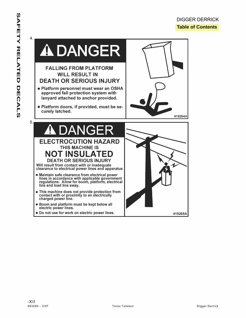


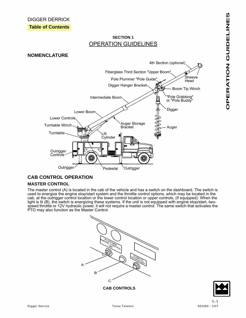


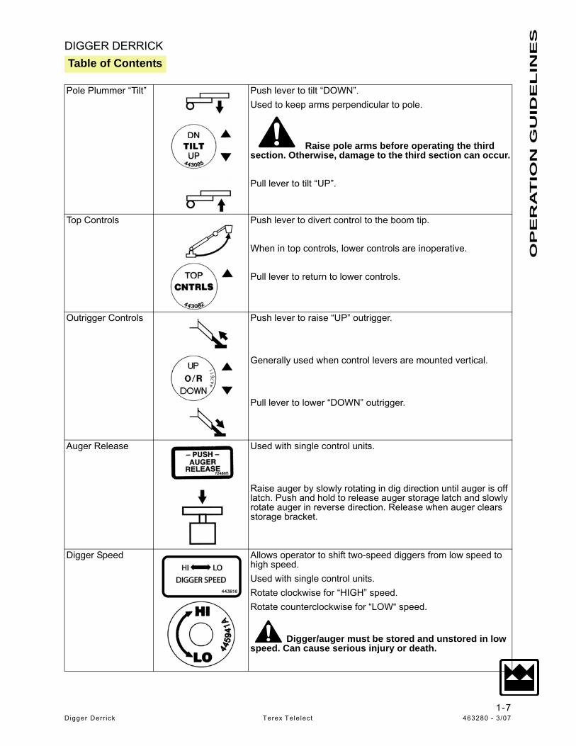


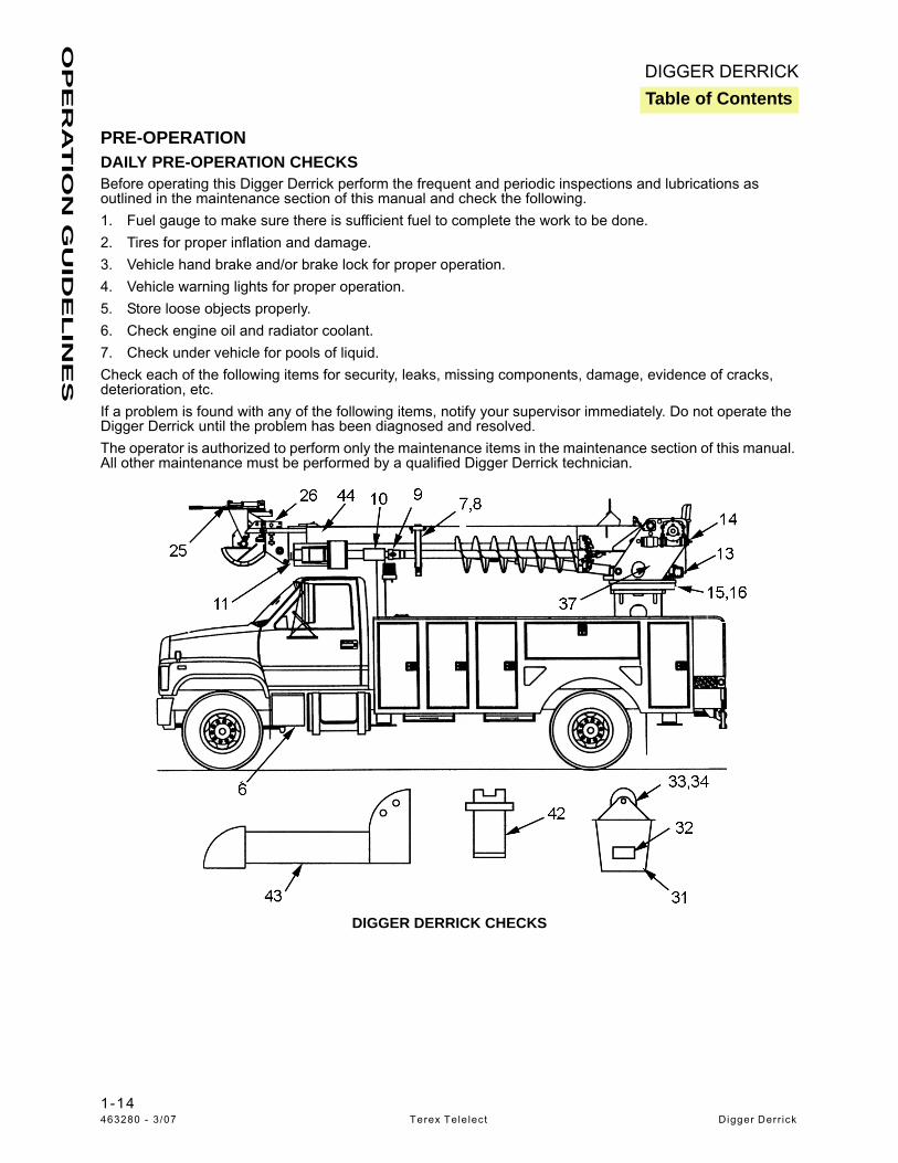


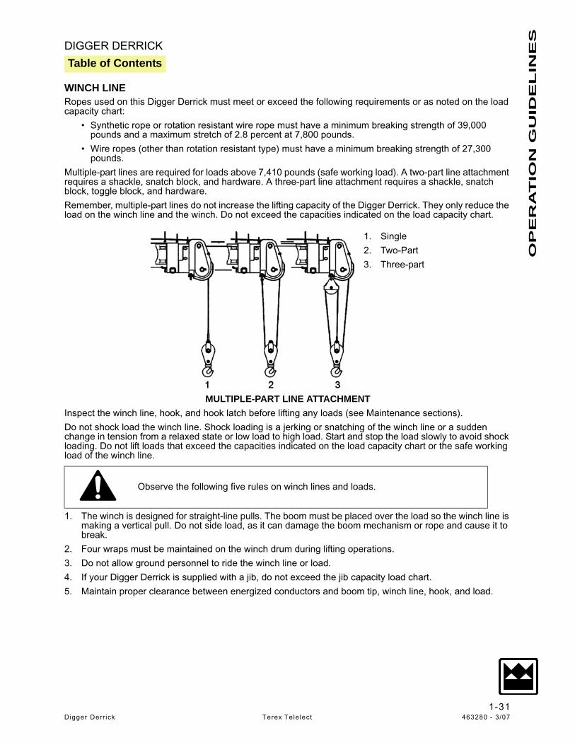


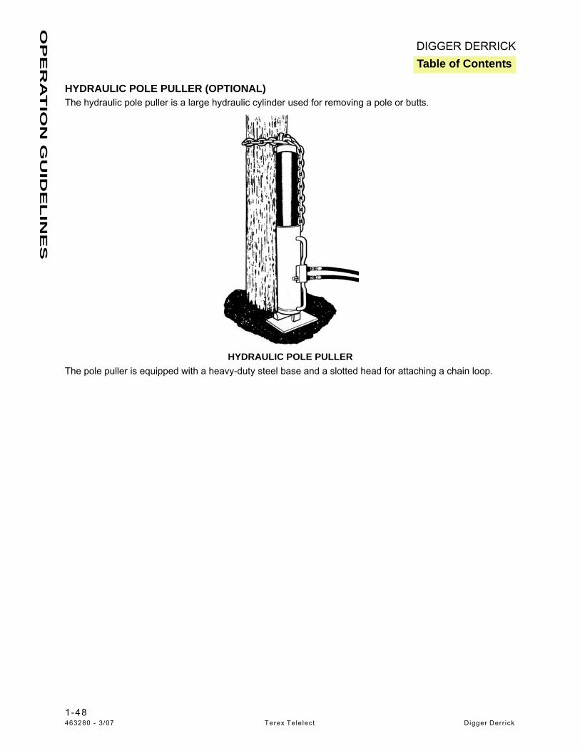


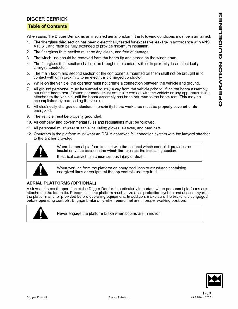


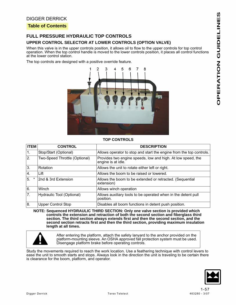


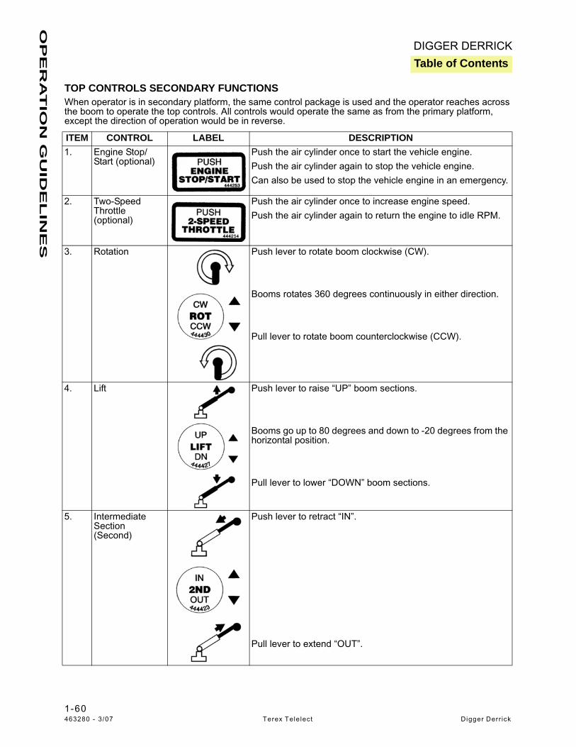


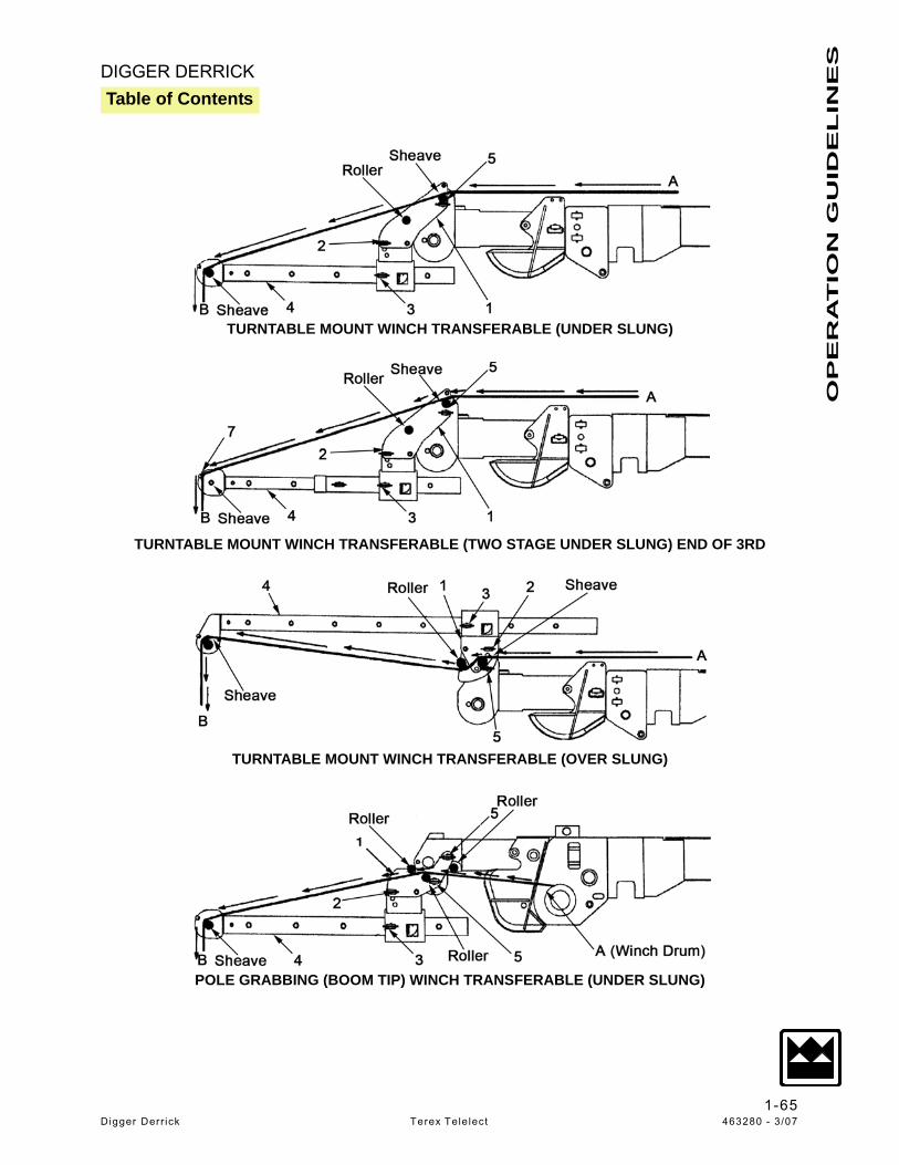
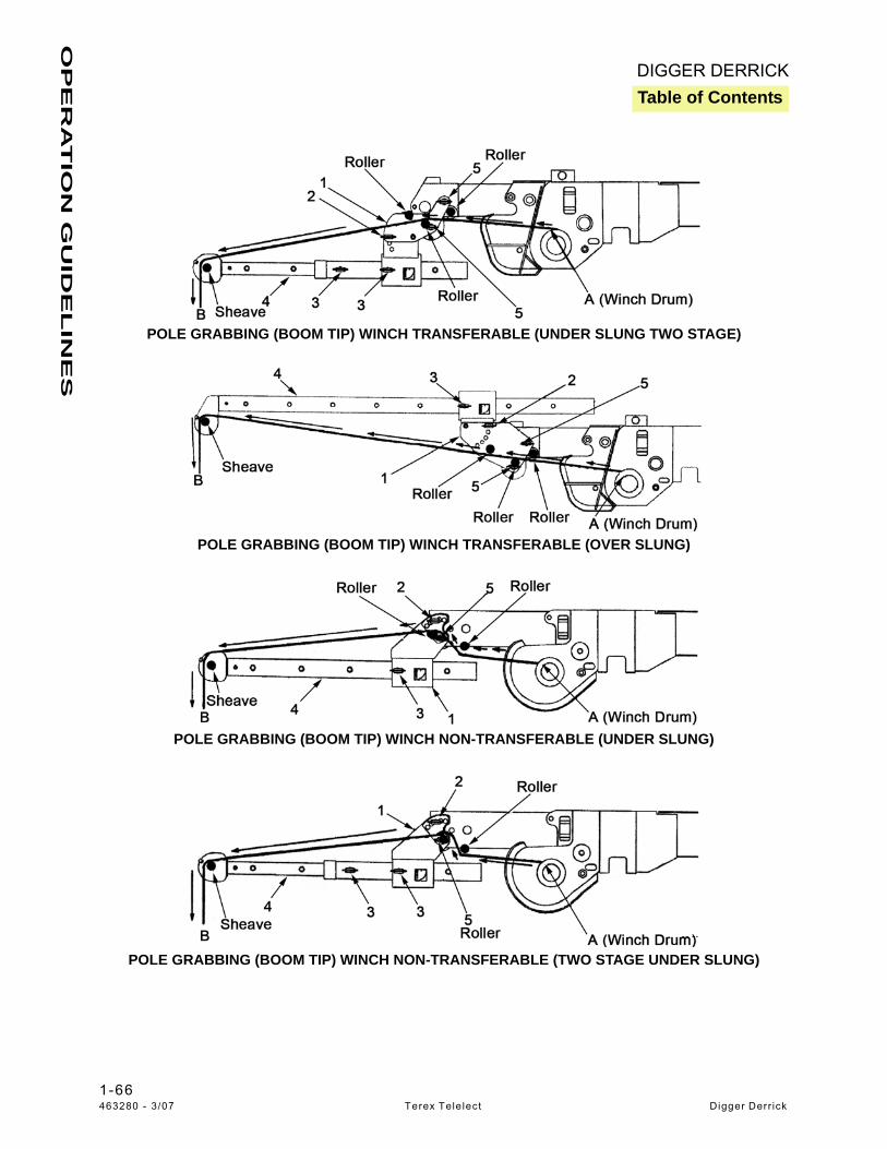


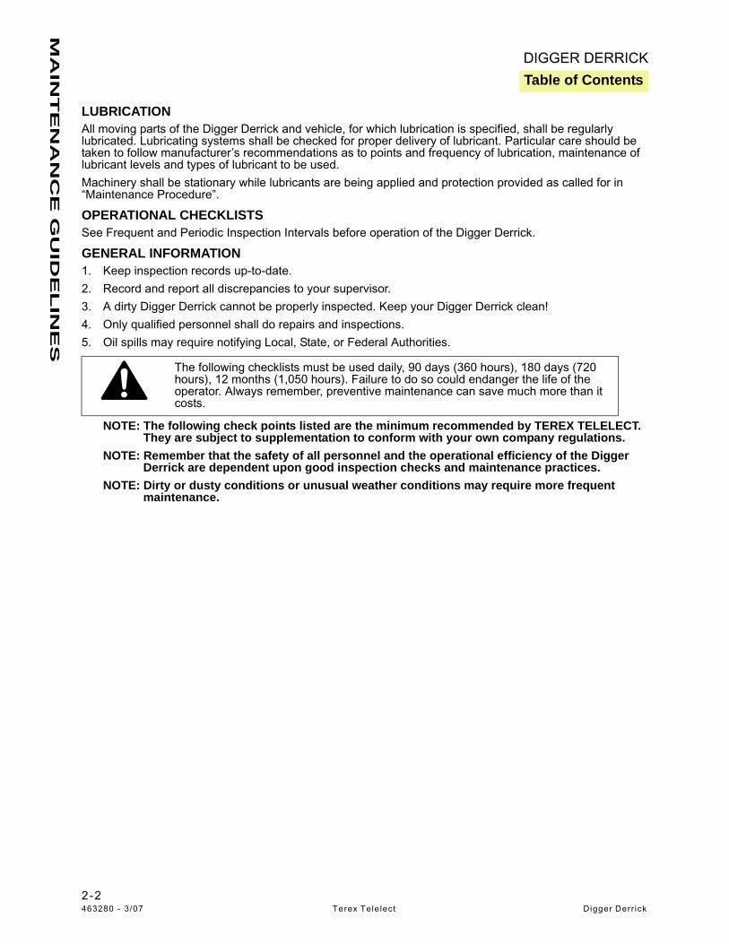


![[Haussmannization, Barricade Fighting]€¦ · [Haussmannization, Barricade Fighting] The flowery realm of decorations, The chann of landscape, of architecnlrc, And all the effect](https://static.documents.pub/doc/80x56/5f02cf237e708231d4061e21/haussmannization-barricade-fighting-haussmannization-barricade-fighting-the.jpg)


