THANK YOU FOR SELECTING A QUALITY PRODUCT BY LINCOLN ELEC TRIC.
PLEASE EXAMINE CARTON AND EQUIPMENT FORDAMAGE IMMEDIATELY
When this equipment is shipped, title passes to the purchaserupon receipt by the carrier. Consequently, claims for materialdamaged in shipment must be made by the purchaser against thetransportation company at the time the shipment is received.
SAFETY DEPENDS ON YOU
Lincoln arc welding and cutting equipment is designed and builtwith safety in mind. However, your overall safety can be increasedby proper installation ... and thoughtful operation on your part. DO NOT INSTALL, OPERATE OR REPAIR THIS EQUIPMENT WITHOUT READING THIS MANUAL AND THE SAFETYPRECAUTIONS CONTAINED THROUGHOUT. And, most importantly,think before you act and be careful.
This statement appears where the information must be followedexactly to avoid serious personal injury or loss of life.
This statement appears where the information must be followedto avoid minor personal injury or damage to this equipment.
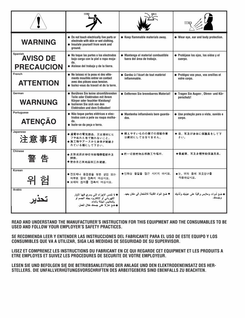
KEEP YOUR HEAD OUT OF THE FUMES.
DON’T get too close to the arc.Use corrective lenses if necessaryto stay a reasonable distanceaway from the arc.
READ and obey the Safety DataSheet (SDS) and the warning labelthat appears on all containers ofwelding materials.
USE ENOUGH VENTILATION orexhaust at the arc, or both, tokeep the fumes and gases from your breathing zone and the general area.
IN A LARGE ROOM OR OUTDOORS, natural ventilation may beadequate if you keep your head out of the fumes (See below).
USE NATURAL DRAFTS or fans to keep the fumes away from your face.
If you de velop unusual symptoms, see your supervisor. Perhaps the welding atmosphere and ventilation system should be checked.
WEAR CORRECT EYE, EAR & BODY PROTECTION
PROTECT your eyes and face with welding helmetproperly fitted and with proper grade of filter plate(See ANSI Z49.1).
PROTECT your body from welding spatter and arcflash with protective clothing including woolenclothing, flame-proof apron and gloves, leatherleggings, and high boots.
PROTECT others from splatter, flash, and glarewith protective screens or barriers.
IN SOME AREAS, protection from noise may be appropriate.
BE SURE protective equipment is in good condition.
Also, wear safety glasses in work areaAT ALL TIMES.
SPECIAL SITUATIONSDO NOT WELD OR CUT containers or materials which previouslyhad been in contact with hazardous substances unless they areproperly cleaned. This is extremely dangerous.
DO NOT WELD OR CUT painted or plated parts unless specialprecautions with ventilation have been taken. They can releasehighly toxic fumes or gases.
Additional precautionary measuresPROTECT compressed gas cylinders from excessive heat,mechanical shocks, and arcs; fasten cylinders so they cannot fall.
BE SURE cylinders are never grounded or part of an electrical circuit.
REMOVE all potential fire hazards from welding area.
ALWAYS HAVE FIRE FIGHTING EQUIPMENT READY FORIMMEDIATE USE AND KNOW HOW TO USE IT.
WARNING
CAUTION
Safety 01 of 04 - 06/15/2016
SECTION A:WARNINGS
CALIFORNIA PROPOSITION 65 WARNINGS
Diesel EnginesDiesel engine exhaust and some of its constituents are known to the State of California to cause cancer, birth defects, and otherreproductive harm.
Gasoline EnginesThe engine exhaust from this product contains chemicals known to the State of California to cause cancer, birth defects, or otherreproductive harm.
ARC WELDING CAN BE HAZARDOUS. PROTECTYOURSELF AND OTHERS FROM POSSIBLE SERIOUSINJURY OR DEATH. KEEP CHILDREN AWAY. PACEMAKER WEARERS SHOULD CONSULT WITHTHEIR DOCTOR BEFORE OPERATING.
Read and understand the following safety highlights. Foradditional safety information, it is strongly recommended that you purchase a copy of “Safety in Welding & Cutting - ANSI Standard Z49.1” from the American Welding Society, P.O. Box 351040, Miami, Florida 33135 or CSA Standard W117.2-1974. A Free copy of “Arc Welding Safety” booklet E205 is available from the Lincoln Electric Company, 22801 St. Clair Avenue, Cleveland, Ohio 44117-1199.
BE SURE THAT ALL INSTALLATION, OPERATION,MAINTENANCE AND REPAIR PROCEDURES AREPERFORMED ONLY BY QUALIFIED INDIVIDUALS.
FOR ENGINE POWEREDEQUIPMENT.
1.a. Turn the engine off before troubleshootingand maintenance work unless themaintenance work requires it to be running.
1.b. Operate engines in open, well-ventilatedareas or vent the engine exhaust fumes outdoors.
1.c. Do not add the fuel near an open flamewelding arc or when the engine is running.Stop the engine and allow it to cool beforerefueling to prevent spilled fuel fromvaporizing on contact with hot engine partsand igniting. Do not spill fuel when fillingtank. If fuel is spilled, wipe it up and do not start engine untilfumes have been eliminated.
1.d. Keep all equipment safety guards, covers and devices in position and in good repair.Keep hands, hair, clothing and tools away from V-belts, gears, fans and all other moving parts when starting, operating orrepairing equipment.
1.e. In some cases it may be necessary to remove safety guards toperform required maintenance. Remove guards only whennecessary and replace them when the maintenance requiringtheir removal is complete. Always use the greatest care whenworking near moving parts.
1.f. Do not put your hands near the engine fan. Do not attempt tooverride the governor or idler by pushing on the throttle controlrods while the engine is running.
1.g. To prevent accidentally starting gasoline engines while turningthe engine or welding generator during maintenance work,disconnect the spark plug wires, distributor cap or magneto wireas appropriate.
1.h. To avoid scalding, do not remove the radiatorpressure cap when the engine is hot.
ELECTRIC ANDMAGNETIC FIELDS MAYBE DANGEROUS
2.a. Electric current flowing through any conductorcauses localized Electric and Magnetic Fields (EMF). Welding current creates EMF fields around welding cables and welding machines
2.b. EMF fields may interfere with some pacemakers, and welders having a pacemaker should consult their physicianbefore welding.
2.c. Exposure to EMF fields in welding may have other health effectswhich are now not known.
2.d. All welders should use the following procedures in order tominimize exposure to EMF fields from the welding circuit:
2.d.1. Route the electrode and work cables together - Securethem with tape when possible.
2.d.2. Never coil the electrode lead around your body.
2.d.3. Do not place your body between the electrode and workcables. If the electrode cable is on your right side, thework cable should also be on your right side.
2.d.4. Connect the work cable to the workpiece as close as pos-sible to the area being welded.
2.d.5. Do not work next to welding power source.
SAFETY
Safety 02 of 04 - 06/15/2016
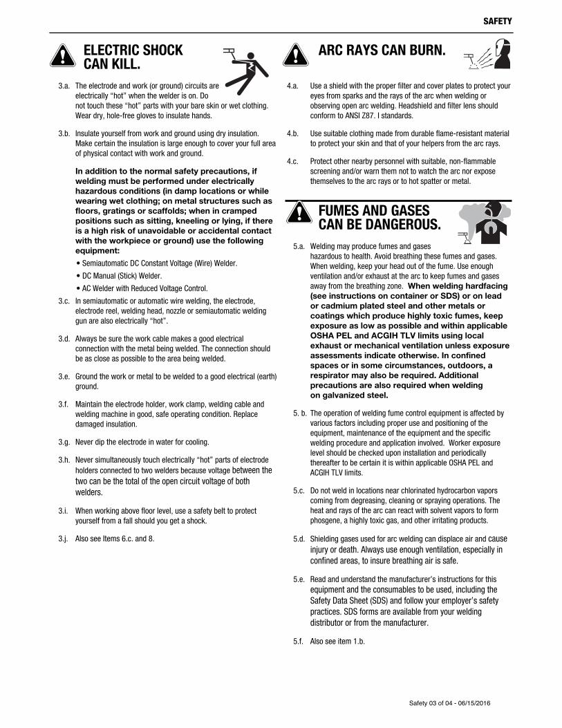
ELECTRIC SHOCK CAN KILL.
3.a. The electrode and work (or ground) circuits areelectrically “hot” when the welder is on. Donot touch these “hot” parts with your bare skin or wet clothing.Wear dry, hole-free gloves to insulate hands.
3.b. Insulate yourself from work and ground using dry insulation.Make certain the insulation is large enough to cover your full areaof physical contact with work and ground.
In addition to the normal safety precautions, ifwelding must be performed under electricallyhazardous conditions (in damp locations or whilewearing wet clothing; on metal structures such asfloors, gratings or scaffolds; when in crampedpositions such as sitting, kneeling or lying, if thereis a high risk of unavoidable or accidental contactwith the workpiece or ground) use the followingequipment:
• Semiautomatic DC Constant Voltage (Wire) Welder.
• DC Manual (Stick) Welder.
• AC Welder with Reduced Voltage Control.
3.c. In semiautomatic or automatic wire welding, the electrode,electrode reel, welding head, nozzle or semiautomatic weldinggun are also electrically “hot”.
3.d. Always be sure the work cable makes a good electricalconnection with the metal being welded. The connection shouldbe as close as possible to the area being welded.
3.e. Ground the work or metal to be welded to a good electrical (earth)ground.
3.f. Maintain the electrode holder, work clamp, welding cable andwelding machine in good, safe operating condition. Replacedamaged insulation.
3.g. Never dip the electrode in water for cooling.
3.h. Never simultaneously touch electrically “hot” parts of electrodeholders connected to two welders because voltage between thetwo can be the total of the open circuit voltage of bothwelders.
3.i. When working above floor level, use a safety belt to protectyourself from a fall should you get a shock.
3.j. Also see It ems 6.c. and 8.
ARC RAYS CAN BURN.
4.a. Use a shield with the proper filter and cover plates to protect youreyes from sparks and the rays of the arc when welding orobserving open arc welding. Headshield and filter lens shouldconform to ANSI Z87. I standards.
4.b. Use suitable clothing made from durable flame-resistant materialto protect your skin and that of your helpers from the arc rays.
4.c. Protect other nearby personnel with suitable, non-flammablescreening and/or warn them not to watch the arc nor exposethemselves to the arc rays or to hot spatter or metal.
FUMES AND GASESCAN BE DANGEROUS.
5.a. Welding may produce fumes and gaseshazardous to health. Avoid breathing these fumes and gases.When welding, keep your head out of the fume. Use enoughventilation and/or exhaust at the arc to keep fumes and gasesaway from the breathing zone. When welding hardfacing(see instructions on container or SDS) or on leador cadmium plated steel and other metals orcoatings which produce highly toxic fumes, keepexposure as low as possible and within applicableOSHA PEL and ACGIH TLV limits using localexhaust or mechanical ventilation unless exposureassessments indicate otherwise. In confinedspaces or in some circumstances, outdoors, arespirator may also be required. Additionalprecautions are also required when welding on galvanized steel.
5. b. The operation of welding fume control equipment is affected byvarious factors including proper use and positioning of theequipment, maintenance of the equipment and the specificwelding procedure and application involved. Worker exposurelevel should be checked upon installation and periodicallythereafter to be certain it is within applicable OSHA PEL andACGIH TLV limits.
5.c. Do not weld in locations near chlorinated hydrocarbon vaporscoming from degreasing, cleaning or spraying operations. Theheat and rays of the arc can react with solvent vapors to formphosgene, a highly toxic gas, and other irritating products.
5.d. Shielding gases used for arc welding can displace air and causeinjury or death. Always use enough ventilation, especially inconfined areas, to insure breathing air is safe.
5.e. Read and understand the manufacturer’s instructions for thisequipment and the consumables to be used, including theSafety Data Sheet (SDS) and follow your employer’s safetypractices. SDS forms are available from your weldingdistributor or from the manufacturer.
5.f. Also see item 1.b.
SAFETY
Safety 03 of 04 - 06/15/2016
WELDING AND CUTTINGSPARKS CAN CAUSEFIRE OR EXPLOSION.
6.a. Remove fire hazards from the welding area. Ifthis is not possible, cover them to prevent the welding sparksfrom starting a fire. Remember that welding sparks and hotmaterials from welding can easily go through small cracks andopenings to adjacent areas. Avoid welding near hydraulic lines.Have a fire extinguisher readily available.
6.b. Where compressed gases are to be used at the job site, specialprecautions should be used to prevent hazardous situations.Refer to “Safety in Welding and Cutting” (ANSI Standard Z49.1)and the operating information for the equipment being used.
6.c. When not welding, make certain no part of the electrode circuit istouching the work or ground. Accidental contact can causeoverheating and create a fire hazard.
6.d. Do not heat, cut or weld tanks, drums or containers until theproper steps have been taken to insure that such procedures will not cause flammable or toxic vapors from substances inside.They can cause an explosion even though they have been“cleaned”. For information, purchase “Recommended SafePractices for the Preparation for Welding and Cutting ofContainers and Piping That Have Held Hazardous Substances”,AWS F4.1 from the American Welding Society (see address above).
6.e. Vent hollow castings or containers before heating, cutting orwelding. They may explode.
6.f. Sparks and spatter are thrown from the welding arc. Wear oil freeprotective garments such as leather gloves, heavy shirt, cufflesstrousers, high shoes and a cap over your hair. Wear ear plugswhen welding out of position or in confined places. Always wearsafety glasses with side shields when in a welding area.
6.g. Connect the work cable to the work as close to the welding areaas practical. Work cables connected to the building framework orother locations away from the welding area increase thepossibility of the welding current passing through lifting chains,crane cables or other alternate circuits. This can create firehazards or overheat lifting chains or cables until they fail.
6.h. Also see item 1.c.
6.I. Read and follow NFPA 51B “Standard for Fire Prevention DuringWelding, Cutting and Other Hot Work”, available from NFPA, 1Batterymarch Park, PO box 9101, Quincy, MA 022690-9101.
6.j. Do not use a welding power source for pipe thawing.
CYLINDER MAY EXPLODE IFDAMAGED.
7.a. Use only compressed gas cylinders containingthe correct shielding gas for the process usedand properly operating regulators designed forthe gas and pressure used. All hoses, fittings,etc. should be suitable for the application andmaintained in good condition.
7.b. Always keep cylinders in an upright position securely chained toan undercarriage or fixed support.
7.c. Cylinders should be located:
• Away from areas where they may be struck or subjectedto physical damage.
• A safe distance from arc welding or cutting operationsand any other source of heat, sparks, or flame.
7.d. Never allow the electrode, electrode holder or any otherelectrically “hot” parts to touch a cylinder.
7.e. Keep your head and face away from the cylinder valve outletwhen opening the cylinder valve.
7.f. Valve protection caps should always be in place and hand tightexcept when the cylinder is in use or connected for use.
7.g. Read and follow the instructions on compressed gas cylinders,associated equipment, and CGA publication P-l, “Precautions forSafe Handling of Compressed Gases in Cylinders,” available fromthe Compressed Gas Association, 14501 George Carter WayChantilly, VA 20151.
FOR ELECTRICALLYPOWERED EQUIPMENT.
8.a. Turn off input power using the disconnectswitch at the fuse box before working on the equipment.
8.b. Install equipment in accordance with the U.S. National ElectricalCode, all local codes and the manufacturer’s recommendations.
8.c. Ground the equipment in accordance with the U.S. NationalElectrical Code and the manufacturer’s recommendations.
TROUBLESHOOTING......................................................................................................................................SECTION EHOW TO USE TROUBLESHOOTING GUIDE................................................................................................................... E-1
WIRING DIAGRAM.........................................................................................................................................SECTION F
PARTS LIST ............................................................................................................... PARTS.LINCOLNELECTRIC.COMCONTENT/DETAILS MAY BE CHANGED OR UPDATED WITHOUT NOTICE. FOR MOST CURRENT INSTRUCTION MANUALS,GO TO PARTS.LINCOLNELECTRIC.COM.
A-1
INSTALLATIONINVERTER ARC 120
INSTALLATIONTECHNICAL SPECIFICATIONS -
K2789-2-InverterArc120
Thermal tests have been performed at ambient temperature. The dutycycle (duty factor) at 40°C has been determined by simulation.
SAFETY PRECAUTIONS
ELECTRIC SHOCK can kill.• Only qualified personnel should
perform this installation.
• Disconnect input power by removingplug from receptacle before workinginside Inverter Arc 120 Allow machineto sit for 5 minutes minimum to allowthe power capacitors to discharge before workinginside this equipment.
• Insulate yourself from the work and ground.
• Always wear dry insulating gloves.
• Always connect the Inverter Arc 120 to a power supplygrounded according to the National Electrical Code andlocal codes.
SELECT SUITABLE LOCATION
This machine can operate in harsh environments.
However, it is important that simple preventative measures arefollowed to assure long life and reliable operation:
• This machine must be located where there is free circulationof clean air without restrictions for air movement to and fromthe air vents. Do not cover the machine with paper, cloth orrags when switched on.
• Dirt and dust that can be drawn into the machine should bekept to a minimum.
• This machine has a protection rating of IP21S. Keep it dryand do not place it on wet ground or in puddles. Do not use inwet or damp locations. Store indoors.
• Locate the machine away from radio controlled machinery.Normal operation may adversely affect the operation ofnearby radio controlled machinery, which may result in injuryor equipment damage. Read the section on electromagneticcompatibility in this manual.
• Do not operate in areas with an ambient temperature greaterthan 40°C.
STACKING
The Inverter Arc 120 cannot be stacked.
TILTING
Place the machine directly on a secure, level surface. Do not placeor operate this machine on a surface with an incline greater than15° from horizontal. The machine may topple over if thisprocedure is not followed.
HIGH FREQUENCY PROTECTION
Locate the Inverter Arc 120 away from radio controlled machinery.The normal operation of the Inverter Arc 120 may adversely affectthe operation of RF controlled equipment, which may result inbodily injury or damage to the equipment.
INPUT - SINGLE PHASE ONLY
Input Voltages 60 Hz. Rated Input Current
120VAC ± 15% 20 AMPS @ RATED OUTPUT
RATED OUTPUT
Duty Cycle Output Amps Output Volts Input Circuit
20% 70A (STICK) 22.8 VDC 120 VAC
OUTPUT
Output Current Range Maximum Open Circuit Voltage Type of Output
10-90 AMPS 75 VOLTS MAX. DC
RECOMMENDED INPUT WIRE AND FUSE SIZES FORMAXIMUM RATED OUTPUT
INPUT VOLTAGE /FREQUENCY (HZ)
TYPE SJT ORHARD USAGEINPUT CORD
MAXIMUM TIME-DELAYCIRCUIT BREAKER OR FUSE
SIZE (AMPS)
120/60 3 CONDUCTOR,14 AWG 20
PHYSICAL DIMENSIONS
Height 9.0 IN. (228.6 MM)
Width 4.5 IN. (114.3 MM)
Depth 13.7 IN. (348.0 MM)
Weight APPROX. 14.0 LBS. (6.4 KGS.)
TEMPERATURE RANGES
OperatingTemperature -10°C TO +40°C
StorageTemperature -25°C TO +55°C
WARNING
A-2
INSTALLATIONINVERTER ARC 120
INPUT CONNECTIONS
GroundConnectionThe frame of the welder must be grounded. Aground terminal marked with the symbol is locatedon the under panel for this purpose. See your localand national electrical codes for proper groundingmethods.
A grounding conductor is suppliedin the input cord, it is importantthat the supply receptacle groundis connected. • The welding power source supply cable
is provided with a green oryellow/green wire that must ALWAYS be earthed. Thisgreen or yellow/green wire must NEVER be used withother voltage conductors.
• Only install plugs that conform with safety regulations.
InputPowerConnectionCheck the input voltage, phase, and frequency supplied to thismachine before turning it on. The allowable input voltage isindicated in the technical specification section of this manual andon the rating plate of the machine. Be sure that the machine isgrounded.
Make sure the power available at the input connection is adequatefor normal operation of the machine. The fuse rating and cablesizes are both indicated in the technical specification section ofthis manual.
Fuse the input circuit with time delay fuses marked “D” or delaytype(1) circuit breakers. Using fuses or circuit breakers smallerthan recommended may result in “nuisance” shut-offs fromwelder inrush currents even if not welding at high currents.(1) Also called “inverse time” or “thermal/magnetic” circuit breakers. These
circuit breakers have a delay in tripping action that decreases as the mag-nitude of the current increases.
The Inverter Arc 120 is recommended for use on an individualbranch circuit.
120v INPUT
The INVERTER ARC™ 120 is provided with a 120V cable,6.0ft.(1.8m) in length, with a 15Amp 5-15P plug molded onto thecord.
The rated output of the INVERTER ARC™ 120 is available whenconnected to a 20A branch circuit. When connected to a branchcircuit with lower ampacity, lower welding current and duty cyclemust be used. An output guide is provided below. The values areapproximate and must be adjusted downward if the fuse or circuitbreaker trips off. Other loads on the circuit and fuse/circuitbreaker characteristics will affect the available output. Do notexceed these welding conditions: (See Table A.1)
TAbleA.1
OUTPUT CONNECTIONS
A quick disconnect system using Twist-Mate™ cable plugs isused for the welding cable connections.
ELECTRIC SHOCK can kill.• Keep the electrode holder and cable
insulation in good condition.
• Do not touch electrically live parts orelectrode with skin or wet clothing.
• Insulate yourself from work and ground.
• Turn the input line Switch on the AUTOPRO™ 90S “off”before connecting or disconnecting output cables orother equipment.
StickWelding(SMAW)Connect the electrode cable to the (+) terminal and the workclamp to the (-) terminal. Insert the connector with the key liningup with the keyway and rotate approximately 1/4 turn clockwise.Do not over tighten.
(See Figure A.1)FIGuReA.1
WARNING
WARNING
Electrode Holder
Work Cable
Positive “+”
Negative “–”
Work Clamp
BRANCH CIRCUITS
120V Input Output Current
PLUG RATING BRANCHRATING
20% DUTYCYCLE
10% DUTYCYCLE
15 AMP 15 AMP 55A 60A
15 AMP 20 AMP 70A 80A
B-1
OPERATION
OPERATIONRead and understand this entire section before operatingyour machine.
Safety PrecautionsDo not attempt to use this equipment until you havethoroughly read all operating and maintenance manualssupplied with your equipment and any related weldingmachine it will be used with. They include important safetyprecautions, operating and maintenance instructions andparts lists.
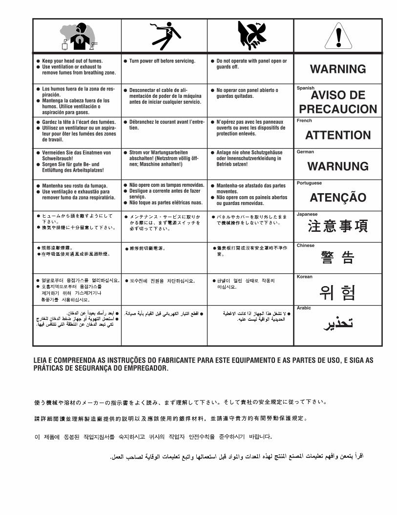
ELECTRIC SHOCK can kill.• Do not touch electrically live parts such asoutput terminals or internal wiring.
• Insulate yourself from the work andground.
• Always wear dry insulating gloves.
WELDING SPARKS can cause fireor explosion.• Keep flammable material away.
• Do not weld upon containers which haveheld combustibles.
ARC RAYS can burn.• Wear eye, ear and body protection.
FUMES AND GASES can be dangerous.Although the removal of the particulatematter from welding smoke may reducethe ventilation requirement, concentrationsof the clear exhausted fumes and gasesmay still be hazardous to health. Avoid breathing concen-trations of these fumes and gases. Use adequateventilation when welding. See ANSI Z49.1, "Safety inWelding and Cutting", published by the American WeldingSociety.
Only qualified personnel should operate this equipment.
Observe all safety information throughout this manual.
GENERAL DESCRIPTION
The INVERTER ARC™ 120 is a 90 amp arc welding power sourcewhich utilizes single phase input power to produce constantcurrent output. The welding response of this Inverter has beenoptimized for stick (SMAW) welding.
WELDING CAPABILITY
The INVERTER ARC™ 120 is rated at 70 amps, 22.8 volts, at 20%duty cycle on a ten minute basis. It is capable of higher dutycycles at lower output currents. If the duty cycle is exceeded, athermal protector will shut off the output until the machine cools.See Table A.1 in the Installation Section for other rated outputs.
The INVERTER ARC™ 120 is recommended for the followingElectrode Types and Diameters:
TAbleA.2
Amp Branch circuit or greater required.∆ - 20 Amp Branch circuit or greater required.
LIMITATIONS
The Inverter Arc 120 is not recommended for pipe thawing.
WARNING
SIZES (IN.)
Types 1/16 5/64 3/32 1/8FLEETWELD 37
(E6013) X X ∆ -
FLEETWELD 35(E6011) - - X ∆
EXCALIBUR 7018 MR(E7018) - - ∆ -
INVERTER ARC 120
B-2
OPERATIONINVERTER ARC 120
CONTROLS AND OPERATIONAL FEATURES
FRONTCONTROlPANel1. Output Current Knob: Potentiometer used to set the output
current used during welding. Set the output according to thetype and size of electrode.
2. Power LED: After the Power Switch is turned on the LED willilluminate.
3. Thermal LED: This indicator will turn on when the machine isoverheated and the output has been disabled. This normallyoccurs when the duty cycle of the machine has beenexceeded. Leave the machine on to allow the internalcomponents to cool. When the indicator turns off, normaloperation is again possible.
4. Positive Quick Disconnect: Positive output connector for thewelding circuit.
6. Power Switch: It turns ON / OFF the input power to themachine.
7. Input cable: This machine is provided with a plugged inputcord. Connect it to the mains.
FIGuReb.2
12
3
4
5
6
7
B-3
OPERATION
ARC-WELDING CIRCUIT
(See Figure B.3)FIGuReb.3
Current flows through the electrode cable and electrode holder tothe electrode and across the arc. On the work side of the arc, thecurrent flows through the base metal to the work cable and backto the welding machine. The circuit must be complete for thecurrent to flow.
To weld, the work clamp must be tightly connected to clean basemetal. Remove paint, rust, etc. as necessary to get a goodconnection. Connect the work clamp as close as possible to thearea you wish to weld. Avoid allowing the welding circuit to passthrough hinges, bearings, electronic components or similardevices that can be damaged.
An electric arc is made between the work and the end of a smallmetal rod, the electrode, which is clamped in a holder and theholder is held by the person doing the welding. A gap is made inthe welding circuit (see Figure B.3) by holding the tip of theelectrode 1/16-1/8” away from the work or base metal beingwelded. The electric arc is established in this gap and is held andmoved along the joint to be welded, melting the metal as it ismoved.
ELECTRIC ARC
(See Figure B.4)
Action that takes place in the electric arc.FIGuReb.4
This figure closely resembles what is actually seen duringwelding. The “arc stream’’ is seen in the middle of the figure. Thisis the electric arc created by the electric current flowing throughthe space between the end of the electrode and the work.
The temperature of this arc is about 6000°F (3315°C), which ismore than enough to melt metal. The arc is very bright, as well ashot, and cannot be looked at with the naked eye without riskingpainful injury. A very dark lens, specifically designed for arcwelding, must be used with a hand or face shield wheneverviewing the arc. The arc melts the base metal and actually digsinto it, much as water through a nozzle on a garden hose digs intothe earth. The molten metal forms a pool or crater and tends toflow away from the arc. As it moves away from the arc, it coolsand solidifies. A slag forms on top of the weld to protect it duringcooling.
The function of the covered electrode is much more than simply tocarry current to the arc. The electrode is composed of a core rodof metal with an extruded chemical covering. The core rod meltsin the arc and tiny droplets of molten metal shoot across the arcinto the molten pool. The electrode provides additional filler metalfor the joint to fill the groove or gap between the two pieces of thebase metal. The covering also melts or burns in the arc. It hasseveral functions. It makes the arc steadier, provides a shield ofsmoke-like gas around the arc to keep oxygen and nitrogen in theair away from the molten metal, and provides a flux for the moltenpool. The flux picks up impurities and forms the protective slag.
Work Cable
Electrode CableWork Clamp
Electrode
Arc
Electrode Holder
Work Piece
INVERTER ARC 120
B-4
OPERATION
MAKING A WELD
Insert the bare part of the electrode into the electrode holder jawsand connect the work clamp to the welding piece. Make sure tohave good electrical contact.
1. Turn the welder on.
2. Lower your welding helmet to protect your face and eyes.
3. Strike the electrode at the work point on the workpiece as ifstriking a match. Do not hit the electrode on the workpiece,which will damage the stick electrode and make striking anarc difficult. Scratch the electrode slowly over the metal andyou will see sparks. While scratching, lift the electrode 1/8"(3.2mm) and the arc will establish.
NOTE: If you stop moving the electrode while scratching, theelectrode will stick.
NOTE: Most beginners try to strike the arc by a fast jabbing motiondown on the plate. Result: They either stick or their motionis so fast that they break the arc immediately.
4. Immediately after striking the arc try to maintain a distancefrom the workpiece that is equivalent to the diameter of theelectrode used. Maintain this distance as constantly aspossible during the weld. Whenever possible, weld from leftto right (if right-handed). Hold the electrode at a slight angleas shown. (See Figure B.5)
FIGuReb.5
5. As the electrode burns off the electrode must be fed to thework to maintain correct arc length. The easiest way to tellwhether the arc has the correct length is by listening to itssound. A nice, short arc has a distinctive, “crackling” sound,very much like eggs frying in a pan. The incorrect, long archas a hollow, blowing or hissing sound.
6. The important thing to watch while welding is the puddle ofmolten metal right behind the arc. Do NOT watch the arcitself. It is the appearance of the puddle and the ridge wherethe molten puddle solidifies that indicate correct weldingspeed. The ridge should be approximately 3/8" (9.5mm)behind the electrode. (See Figure B.6)
FIGuReb.6
Most beginners tend to weld too fast, resulting in a thin, uneven,“wormy” looking bead. They are not watching the molten metal.
IMPORTANT: For general welding it is not necessary to weave thearc; neither forwards and backwards nor sideways. Weldalong at a steady pace. You will find it easier. NOTE: Whenwelding on thin plate, you will find that you will have toincrease the welding speed, whereas when welding on heavyplate, it is necessary to go more slowly in order to get goodpenetration.
7. Once the electrode is burned down move the electrodequickly from the weld to extinguish the arc.
8. Turn the machine off and remove the stub by opening thejaws of the electrode holder and insert a new electrode.
Note: The welded work piece and electrode stub are hot afterwelding. Allow them to cool down before touching or usepliers to move. Always make sure the welder is turned offbefore setting down the Electrode Holder.
INVERTER ARC 120
C-1
ACCESSORIES
OPTIONAL KITS ANDACCESSORIES
INVERTER ARC 120
D-1
MAINTENANCE
MAINTENANCE
ELECTRIC SHOCK can kill.• Turn the input power OFF at the welding
power source before installation orchanging drive rolls and/or guides.
• Do not touch electrically live parts.
• When inching with the gun trigger, electrode and drivemechanism are "hot" to work and ground and couldremain energized several seconds after the gun triggeris released.
• Do not operate with covers, panels or guards removedor open.
• Only qualified personnel should perform maintenancework.
ROUTINE MAINTENANCE
The frequency of the maintenance operations may vary inaccordance with the working environment. Any noticeabledamage should be reported immediately.
• Check cables and connections integrity. Replace, ifnecessary.
• Clean the power source inside by means of low - pressurecompressed air.
• Keep the machine clean. Use a soft dry cloth to clean theexternal case, especially the airflow inlet / outlet louvers.
Do not open this machine and do not intro-duce anything into its openings. Power supplymust be disconnected from the machinebefore each maintenance and service. Aftereach repair, perform proper tests to ensuresafety.
Power supply must be disconnected from themachine before each maintenance and ser-vice. Always use gloves in compliance withthe safety standards.
TROUBLESHOOTINGHOW TO USE TROUBLESHOOTING GUIDE
Service and Repair should only be performed by LincolnElectric Factory Trained Personnel. Unauthorized repairsperformed on this equipment may result in danger to thetechnician and machine operator and will invalidate yourfactory warranty. For your safety and to avoid ElectricalShock, please observe all safety notes and precautionsdetailed throughout this manual.
This Troubleshooting Guide is provided to help you locate andrepair possible machine malfunctions. Simply follow the three-step procedure listed below.
Step 1. LOCATE PROBLEM (SYMPTOM).
Look under the column labeled “PROBLEM (SYMPTOMS).” Thiscolumn describes possible symptoms that the machine mayexhibit. Find the listing that best describes the symptom that themachine is exhibiting.
Step 2. POSSIBLE CAUSE.The second column labeled “POSSIBLE CAUSE” lists the obviousexternal possibilities that may contribute to the machine symptom. Step 3. RECOMMENDED COURSE OF ACTIONThis column provides a course of action for the Possible Cause,generally it states to contact you local Lincoln Authorized FieldService Facility.
If you do not understand or are unable to perform theRecommended Course of Action safely, contact your local Lincoln Authorized Field Service Facility.
E
ELECTRIC SHOCK can kill.• Turn off machine at the disconnect switch
on the rear of the machine and removemain power supply connections beforedoing any troubleshooting.
If for any reason you do not understand the test procedures or are unable to perform the tests/repairs safely, contact your Lincoln Authorized Service Facility for technical troubleshooting assistance before you proceed.WWW.LINCOLNELECTRIC.COM/LOCATOR
PROBLEM(SYMPTOMS)
POSSIBLE AREAS OF MISADJUSTMENT(S) RECOMMENDED COURSE OF ACTION
WelDINGPRObleMSExcessive spatter 1. Improper welding polarity. 1. Make sure the electrode holder is plugged into the
positive “+” output terminal.
2. Long Arc Length. 2. Move the electrode closer into the weld joint.
3. High Current. 3. Turn the output knob down.
Craters 1. Fast movement of the electrode away fromthe work piece.
1. Maintain a steady consistent arc length
Inclusions 1. Poor cleanliness. 1. Clean work piece with wire brush prior to welding.
2. Poor distribution of the welding passes. 2. Consult a welding guide for proper weld beadplacement.
Insufficient penetration 1. High travel speed. 1. Travel at a slower speed.
2. Welding current is too low. 2. Adjust welding output higher.
Electrode Sticking 1. Arc length is too short. 1. Move the electrode further away from the weld joint.
2. Welding current is too low. 2. Turn the output knob up.
Porosity 1. Humidity in the electrode. 1. Store welding electrodes in a warm dry place.
2. Long arc length. 2. Move the electrode closer into the weld joint.
Cracks 1. Weld current is set too high. 1. Turn the output knob down.
2. Dirty materials. 2. Clean work piece with wire brush prior to welding.
3. Hydrogen in the weld due to moisture. 3. Store welding electrodes in a warm dry place.
eleCTRICAlFAIluReS
Machine fails to come on
(Power LED off)
1. No Input Voltage.
If all recommended possible areas of misadjustmenthave been checked and the problem persists, Contactyour local Authorized Field Service Facility.
2. Faulty supply plug or cable.
3. Supply fuse blown or breaker tripped.
Thermal overload
(Thermal LED on)
1. Unit has been operated beyond its capacityrating.
2. Airflow through machine is restricted orfan has failed.
The fan works, but theoutput current is unstableand can not be controlled bythe potentiometer whilewelding is carried out.
1. Check the output current potentiometer,and replace it if necessary.
2. Verify output cables are attached to thewelder and tightly connected
G-1
DIAGRAMSINVERTER ARC 120
NOTE
: Th
is dia
gram
is fo
r ref
eren
ce o
nly.
It m
ay n
ot b
e ac
cura
te fo
r all m
achin
es co
vere
d by
this
man
ual.
The
spec
ific d
iagra
m fo
r a p
artic
ular c
ode
is pa
sted
inside
the
mac
hine
on o
ne o
f the
enc
losur
e pa
nels.
If t
he d
iagra
m is
illeg
ible,
writ
e to
the
Serv
ice D
epar
tmen
t for
a re
place
men
t. G
ive th
e eq
uipm
ent c
ode
num
ber.
HT+
OU
T+
Iac
v
12
12 12
2
53
6
41
1/4
1 3-
4
+2
AG
ND
OU
T-
3
2133 4
244
1
34
B J2 1
A
VR
1O
utpu
t Con
trol
LED
3LE
D4
Fron
t of M
achi
ne
AC
2
AC
1AC
120V
Rea
r of M
achi
ne
Fan
1/4
1/4
WIRINGDIAG
RAMFOR
COD
e12744
WARNING
AVISO DEPRECAuCION
ATTENTION
WARNuNG
ATENÇÃO
Spanish
French
German
Portuguese
Japanese
Chinese
Korean
Arabic
READ AND UNDERSTAND THE MANUFACTURER’S INSTRUCTION FOR THIS EQUIPMENT AND THE CONSUMABLES TO BEUSED AND FOLLOW YOUR EMPLOYER’S SAFETY PRACTICES.
SE RECOMIENDA LEER Y ENTENDER LAS INSTRUCCIONES DEL FABRICANTE PARA EL USO DE ESTE EQUIPO Y LOSCONSUMIBLES QUE VA A UTILIZAR, SIGA LAS MEDIDAS DE SEGURIDAD DE SU SUPERVISOR.
LISEZ ET COMPRENEZ LES INSTRUCTIONS DU FABRICANT EN CE QUI REGARDE CET EQUIPMENT ET LES PRODUITS AETRE EMPLOYES ET SUIVEZ LES PROCEDURES DE SECURITE DE VOTRE EMPLOYEUR.
LESEN SIE UND BEFOLGEN SIE DIE BETRIEBSANLEITUNG DER ANLAGE UND DEN ELEKTRODENEINSATZ DES HER-STELLERS. DIE UNFALLVERHÜTUNGSVORSCHRIFTEN DES ARBEITGEBERS SIND EBENFALLS ZU BEACHTEN.
l Do not touch electrically live parts orelectrode with skin or wet clothing.
l Insulate yourself from work andground.
l No toque las partes o los electrodosbajo carga con la piel o ropa moja-da.
l Aislese del trabajo y de la tierra.
l Ne laissez ni la peau ni des vête-ments mouillés entrer en contactavec des pièces sous tension.
l Isolez-vous du travail et de la terre.
l Berühren Sie keine stromführendenTeile oder Elektroden mit IhremKörper oder feuchter Kleidung!
l Isolieren Sie sich von denElektroden und dem Erdboden!
l Não toque partes elétricas e elec-trodos com a pele ou roupa molha-da.
l Isole-se da peça e terra.
l Keep flammable materials away.
l Mantenga el material combustiblefuera del área de trabajo.
l Gardez à l’écart de tout matérielinflammable.
l Entfernen Sie brennbarres Material!
l Mantenha inflamáveis bem guarda-dos.
l Wear eye, ear and body protection.
l Protéjase los ojos, los oídos y elcuerpo.
l Protégez vos yeux, vos oreilles etvotre corps.
l Tragen Sie Augen-, Ohren- und Kör-perschutz!
l Use proteção para a vista, ouvido ecorpo.
WARNING
AVISO DEPRECAuCION
ATTENTION
WARNuNG
ATENÇÃO
Spanish
French
German
Portuguese
Japanese
Chinese
Korean
Arabic
LEIA E COMPREENDA AS INSTRUÇÕES DO FABRICANTE PARA ESTE EQUIPAMENTO E AS PARTES DE USO, E SIGA ASPRÁTICAS DE SEGURANÇA DO EMPREGADOR.
l Keep your head out of fumes.l Use ventilation or exhaust to
remove fumes from breathing zone.
l Los humos fuera de la zona de res-piración.
l Mantenga la cabeza fuera de loshumos. Utilice ventilación oaspiración para gases.
l Gardez la tête à l’écart des fumées.l Utilisez un ventilateur ou un aspira-
teur pour ôter les fumées des zonesde travail.
l Vermeiden Sie das Einatmen vonSchweibrauch!
l Sorgen Sie für gute Be- undEntlüftung des Arbeitsplatzes!
l Mantenha seu rosto da fumaça.l Use ventilação e exhaustão para
remover fumo da zona respiratória.
l Turn power off before servicing.
l Desconectar el cable de ali-mentación de poder de la máquinaantes de iniciar cualquier servicio.
l Débranchez le courant avant l’entre-tien.
l Strom vor Wartungsarbeitenabschalten! (Netzstrom völlig öff-nen; Maschine anhalten!)
l Não opere com as tampas removidas.l Desligue a corrente antes de fazer
serviço.l Não toque as partes elétricas nuas.
l Do not operate with panel open orguards off.
l No operar con panel abierto oguardas quitadas.
l N’opérez pas avec les panneauxouverts ou avec les dispositifs deprotection enlevés.
l Anlage nie ohne Schutzgehäuseoder Innenschutzverkleidung inBetrieb setzen!
l Mantenha-se afastado das partesmoventes.
l Não opere com os paineis abertosou guardas removidas.
CUSTOMER ASSISTANCE POLICY
The business of The Lincoln Electric Company is manufacturing andselling high quality welding equipment, consumables, and cuttingequipment. Our challenge is to meet the needs of our customers andto exceed their expectations. On occasion, purchasers may askLincoln Electric for advice or information about their use of ourproducts. We respond to our customers based on the best informationin our possession at that time. Lincoln Electric is not in a position towarrant or guarantee such advice, and assumes no liability, withrespect to such information or advice. We expressly disclaim anywarranty of any kind, including any warranty of fitness for anycustomer’s particular purpose, with respect to such information oradvice. As a matter of practical consideration, we also cannot assumeany responsibility for updating or correcting any such information oradvice once it has been given, nor does the provision of informationor advice create, expand or alter any warranty with respect to the saleof our products.
Lincoln Electric is a responsive manufacturer, but the selection anduse of specific products sold by Lincoln Electric is solely within thecontrol of, and remains the sole responsibility of the customer. Manyvariables beyond the control of Lincoln Electric affect the resultsobtained in applying these types of fabrication methods and servicerequirements.
Subject to Change – This information is accurate to the best of ourknowledge at the time of printing. Please refer to www.lincolnelectric.com for any updated information.


![Journal of American Science 0203arc welding, atomic hydrogen welding, shielded metal arc welding, plasma arc welding, electroslag welding, etc. Arc welding has been described [3] to](https://static.documents.pub/doc/80x56/5ec0a6e76045b75960496969/journal-of-american-science-arc-welding-atomic-hydrogen-welding-shielded-metal.jpg)


