800-456-7100 I www.paladinlcg.com 503 Gay Street, Delhi, IA 52223, United States of America SERIAL NUMBER: ___________________ Manual Number: 76827 Part Number: 76827 MODEL NUMBER: ___________________ Rev. 2: January 27, 2010 OPERATOR’S & PARTS MANUAL 48” - 66” SIDE TILT FORK CARRIAGE M-1131 1-25-10-2
Transcript
800-456-7100 I www.paladinlcg.com 503 Gay Street, Delhi, IA 52223, United States of America
SERIAL NUMBER: ___________________ Manual Number: 76827 Part Number: 76827 MODEL NUMBER: ___________________ Rev. 2: January 27, 2010
OPERATOR’S & PARTS MANUAL
48” - 66” SIDE TILTFORK CARRIAGE
M-1131 1-25-10-2
M-920 2-11-10-2
PREFACE....................................................................................................................................3SAFETY PRECAUTIONS ....................................................................................................... 4-7 SAFETY STATEMENTS .......................................................................................................................................4 GENERAL SAFETY PRECAUTIONS................................................................................................................4-6 EQUIPMENT SAFETY PRECAUTIONS ..............................................................................................................7INSTALLATION AND OPERATION ............................................................................................8 ATTACHING ..........................................................................................................................................................8 DETACHING ..........................................................................................................................................................8MAINTENANCE AND SERVICE ............................................................................................9-11 GENERAL INFORMATION .....................................................................................................................................9 DAILY ....................................................................................................................................................................9 EVERY 40 HOURS ...............................................................................................................................................9LIMITED WARRANTY ..............................................................................................................13PARTS SIDE TILT FORK CARRIAGES 48” SIDE TILT FORK CARRIAGE ASSEMBLY #11338 ........................................................................16-17 48” SIDE TILT FORK CARRIAGE ASSEMBLY #12646 .......................................................................18-19 60” SIDE TILT FORK CARRIAGE ASSEMBLY #11414 .......................................................................20-21 60” SIDE TILT FORK CARRIAGE ASSEMBLY #12647 .......................................................................22-23 CYLINDERS CYLINDER ASSEMBLY #19309 ............................................................................................................24-25 CYLINDER ASSEMBLY #89113 ............................................................................................................26-27
TABLE OF CONTENTS
76827 1
THIS PAGEIS INTENTIONALLY
BLANK
2 76827
PREFACE
GENERAL COMMENTSCongratulations on the purchase of your new attachment! This product was carefully
designed and manufactured to give you many years of dependable service. Only minormaintenance, such as cleaning and lubricating, is required to keep it in top working condition. Besure to observe all maintenance procedures and safety precautions in this manual and on anysafety decals located on the product, and on any equipment on which the attachment is mounted.Also, check load charts before operating the attachment.
This manual has been designed to help you do a better, safer job. Read this manualcarefully and become familiar with its contents.
WARNING! Never let anyone operate this unit without reading the “Safety Precautions”and “Operating Instructions” sections of this manual.Always choose hard, level ground to park the vehicle on, and set the brakeso the unit cannot roll.
Unless noted otherwise, right and left sides are determined from the operator’s controlposition when facing the attachment.
NOTE: The illustrations and data used in this manual were current, according to theinformation available to us at the time of printing. However, we reserve the right toredesign and change the attachment as may be necessary, without notification.
BEFORE OPERATIONThe primary responsibility for safety with this equipment falls to the operator. Make sure
the equipment is operated only by trained individuals who have read and understand this manual.If there is any portion of this manual or function that you do not understand, contact your localauthorized dealer or the manufacturer.
SAFETY ALERT SYMBOLThis is the “Safety Alert Symbol” used by this industry. This symbol is used to warnof possible injury. Be sure to read all warnings carefully. They are included for yoursafety and for the safety of others working with you.
SERVICEWhen servicing your product, remember to use only manufacturer replacement parts.
Substitute parts may not meet the standards required for safe, dependable operation.To facilitate parts ordering, record the model and serial number of your unit in the space
provided on the cover of this manual. This information may be obtained from the identificationplate located on the product.
The parts department needs this information to ensure that you receive the correct parts foryour specific model.
M-934 9-21-05-2
76827 3
M-806 7-28-05-2
SAFETY STATEMENTS
DANGER
GENERAL SAFETY PRECAUTIONS
WARNING! READ MANUAL PRIOR TO INSTALLATIONImproper installation, operation, or maintenance of this equipment could result inserious injury or death. Operators and maintenance personnel should read thismanual, as well as all manuals related to this equipment and the prime moverthoroughly before beginning installation, operation, or maintenance. FOLLOW ALLSAFETY INSTRUCTIONS IN THIS MANUAL AND THE PRIME MOVER’SMANUAL(S).
READ AND UNDERSTAND ALL SAFETY STATEMENTSRead all safety decals and safety statements in all manuals prior to operating orworking on this equipment. Know and obey all OSHA regulations, local laws, andother professional guidelines for your operation. Know and follow good work practiceswhen assembling, maintaining, repairing, mounting, removing, or operating thisequipment.
KNOW YOUR EQUIPMENTKnow your equipment’s capabilities, dimensions, and operations before operating.Visually inspect your equipment before you start, and never operate equipment that isnot in proper working order with all safety devices intact. Check all hardware toensure it is tight. Make certain that all locking pins, latches, and connection devicesare properly installed and secured. Remove and replace any damaged, fatigued, orexcessively worn parts. Make certain all safety decals are in place and are legible.Keep decals clean, and replace them if they become worn or hard to read.
WARNING
CAUTION
THIS SIGNAL WORD IS USED WHERE SERIOUS INJURY OR DEATHWILL RESULT IF THE INSTRUCTIONS ARE NOT FOLLOWED PROPERLY.
THIS SIGNAL WORD IS USED WHERE SERIOUS INJURY OR DEATHCOULD RESULT IF THE INSTRUCTIONS ARE NOT FOLLOWED PROP-ERLY.
THIS SIGNAL WORD IS USED WHERE MINOR INJURY COULD RESULT IFTHE INSTRUCTIONS ARE NOT FOLLOWED PROPERLY.
NOTICE INDICATES A PROPERTY DAMAGE MESSAGE. NOTICE
THIS SYMBOL BY ITSELF OR WITH A WARNING WORD THROUGHOUT THISMANUAL IS USED TO CALL YOUR ATTENTION TO INSTRUCTIONS INVOLVINGYOUR PERSONAL SAFETY OR THE SAFETY OF OTHERS. FAILURE TO FOLLOWTHESE INSTRUCTIONS CAN RESULT IN INJURY OR DEATH.
4 76827
GENERAL SAFETY PRECAUTIONS
WARNING! PROTECT AGAINST FLYING DEBRISAlways wear proper safety glasses, goggles, or a face shield when driving pins in orout, or when any operation causes dust, flying debris, or any other hazardous mate-rial.
WARNING! LOWER OR SUPPORT RAISED EQUIPMENTDo not work under raised booms without supporting them. Do not use support mate-rial made of concrete blocks, logs, buckets, barrels, or any other material that couldsuddenly collapse or shift positions. Make sure support material is solid, not decayed,warped, twisted, or tapered. Lower booms to ground level or on blocks. Lower boomsand attachments to the ground before leaving the cab or operator’s station.
WARNING! USE CARE WITH HYDRAULIC FLUID PRESSUREHydraulic fluid under pressure can penetrate the skin and cause serious injury ordeath. Hydraulic leaks under pressure may not be visible. Before connecting ordisconnecting hydraulic hoses, read your prime mover’s operator’s manual fordetailed instructions on connecting and disconnecting hydraulic hoses or fittings.
• Keep unprotected body parts, such as face, eyes, and arms as far away aspossible from a suspected leak. Flesh injected with hydraulic fluid may developgangrene or other permanent disabilities.
• If injured by injected fluid, see a doctor at once. If your doctor is not familiar withthis type of injury, ask him to research it immediately to determine proper treat-ment.
• Wear safety glasses, protective clothing, and use a piece of cardboard or woodwhen searching for hydraulic leaks. DO NOT USE YOUR HANDS! SEE ILLUS-TRATION.
CARDBOARD
HYDRAULIC HOSEOR FITTING
MAGNIFYING GLASS
M-807 7-28-05-2
76827 5
GENERAL SAFETY PRECAUTIONS
M-808 7-28-05-2
WARNING! DO NOT MODIFY MACHINE OR ATTACHMENTSModifications may weaken the integrity of the attachment and may impair the function,safety, life, and performance of the attachment. When making repairs, use only themanufacturer’s genuine parts, following authorized instructions. Other parts may besubstandard in fit and quality. Never modify any ROPS (Roll Over Protection Struc-ture) or FOPS (Falling Object Protective Structure) equipment or device. Any modifi-cations must be authorized in writing by the manufacturer.
WARNING! SAFELY MAINTAIN AND REPAIR EQUIPMENT• Do not wear loose clothing or any accessories that can catch in moving parts. If
you have long hair, cover or secure it so that it does not become entangled in theequipment.
• Work on a level surface in a well-lit area.• Use properly grounded electrical outlets and tools.• Use the correct tools for the job at hand. Make sure they are in good condition for
the task required.• Wear the protective equipment specified by the tool manufacturer.
SAFELY OPERATE EQUIPMENTDo not operate equipment until you are completely trained by a qualified operator inhow to use the controls, know its capabilities, dimensions, and all safety require-ments. See your machine’s manual for these instructions.• Keep all step plates, grab bars, pedals, and controls free of dirt, grease, debris,
and oil.• Never allow anyone to be around the equipment when it is operating.• Do not allow riders on the attachment or the prime mover.• Do not operate the equipment from anywhere other than the correct operator’s
position.• Never leave equipment unattended with the engine running, or with this attach-
ment in a raised position.• Do not alter or remove any safety feature from the prime mover or this attach-
ment.• Know your work site safety rules as well as traffic rules and flow. When in doubt
on any safety issue, contact your supervisor or safety coordinator for an explana-tion.
6 76827
EQUIPMENT SAFETY PRECAUTIONS
WARNING! KNOW WHERE UTILITIES AREObserve overhead electrical and other utility lines. Be sure equipment will clearthem. When digging, call your local utilities for location of buried utility lines, gas,water, and sewer, as well as any other hazard you may encounter.
OPERATING THE PRIME MOVERAvoid steep hillside operation, which could cause the prime mover to overturn.Consult your machine operator’s and safety manuals for maximum incline allowable.
When operating on a slope, keep the load low, and proceed with extreme caution.Do not drive ACROSS a steep slope - drive straight up and down.With LOADED forks - drive with the forks and load facing uphill.With EMPTY forks - drive with the forks facing downhill.
WORKING WITH THE ATTACHMENT• Never use the attachment for a work platform or personnel carrier.• Specified lift capacities must not be exceeded, otherwise machine stability will
not be sufficient. Always observe lift capacity limits listed in machine specifica-tions or on load charts furnished with the prime mover.
• An operator must not use drugs or alcohol, which can change his or her alert-ness or coordination. An operator taking prescription or over-the-counter drugsshould seek medical advice on whether or not he or she can safely operateequipment.
• Always check locking pins before operating any attachment.• Never lift, move, or swing loaded forks over anyone.• Always space the forks correctly for the load. Loads can fall off incorrectly
spaced forks. Make sure the forks are completely under the load before lifting.• Never stack loads on uneven ground. Loads stacked on uneven ground can
topple.• Never lift a load with one fork. A load lifted with one fork can slip off and cause
injury.• Secure loads properly. Unsecured loads can fall unexpectedly.• Do not handle round bales with fork lift tines.• Don’t obstruct your vision when traveling or working. Carry the forks low for
maximum stability and visibility.
MAINTAINING THE ATTACHMENT• Never perform any work on the equipment unless you are authorized and quali-
fied to do so. Always read the operator’s and service manual(s) before any repairis made. After completing maintenance or repair, check for correct functioning ofthe attachment. If not functioning properly, always attach a “DO NOT OPERATE”tag to the machine until all problems are corrected.
• Worn, damaged, or illegible safety decals must be replaced. New safety decalscan be ordered from the manufacturer.
M-1014 8-23-05
76827 7
INSTALLATION AND OPERATION
M-851 5-31-05
ATTACHING AND DETACHING EQUIPMENTPlease see your vehicle operator’s manual for instructions on attaching and detaching your equipment.
OPERATING EQUIPMENTRead all Safety Precautions before operating your new attachment. If you have not been supplied witha load chart for your attachment, order one from your dealer, and place it inside the operating machinefor safe lift capacity limits.
Refer to your machine operator’s manual for attachment operation.
SIDE TILT FORK CARRIAGEWhen using the tilt feature keep the load as level as possible, using extreme caution when driving off ofa slope to reposition the forks, to prevent the load from sliding off of the forks or pallet.
NOTE: If the carriage tilts or drifts due to oil leakage within the cylinder assembly, discontinue use until the problem has been corrected.
When using the shift feature to pick up a load, be sure to return the forks and load to the center posi-tion as soon as possible. Do NOT travel with loaded forks shifted to the side.
8 76827
M-852 5-27-05
MAINTENANCE & SERVICE
GENERAL INFORMATIONRegular maintenance is the key to long equipment life and safe operation. Maintenance
requirements have been kept to an absolute minimum. However, it is very important that thesemaintenance functions be performed as described in this section.
DAILY• Check all bolts and nuts for tightness.• Replace any missing bolts or nuts with approved replacement parts.• Check hydraulic system for hydraulic oil leaks. See procedure below.• Visually inspect the machine for worn parts or cracked welds, and repair
as necessary.
WARNING! Escaping fluid under pressure can have sufficient force to penetrate theskin, causing serious personal injury. Fluid escaping from a very small holecan be almost invisible. Use a piece of cardboard or wood, rather thanhands to search for suspected leaks.Keep unprotected body parts, such as face, eyes, and arms as far away aspossible from a suspected leak. Flesh injected with hydraulic fluid maydevelop gangrene or other permanent disabilities.If injured by injected fluid, see a doctor at once. If your doctor is not familiarwith this type of injury, ask him or her to research it immediately to deter-mine proper treatment.
CARDBOARD
HYDRAULIC HOSE ORFITTING MAGNIFYING GLASS
Lubrication is an important part of maintenance. It is recommended that all grease fittings belubricated after the intitial 8 hours of operation, and then after every 40 hours of use.
EVERY 40 HOURS
IMPORTANT: When replacing parts, use only factory approved replacement parts. Manu-facturer will not claim responsibility for use of unapproved parts or accessories and/orother damages as a result of their use.
76827 9
MAINTENANCE AND SERVICE
10356 10-13-05
CYLINDER SEAL REPLACEMENT The following information is provided to assist you in the event you should need to repair or rebuild a hy-draulic cylinder. When working on hydraulic cylinders, make sure that the work area and tools are clean and free of dirt to prevent contamination of the hydraulic system and damage to the hydraulic cylinders. Always protect the active part of the cylinder rod (the chrome section). Nicks or scratches on the surface of the rod could result in cylinder failure. Clean all parts thoroughly with a cleaning solvent before reassembly.
DISASSEMBLY PROCEDUREIMPORTANT: Do not contact the active surface of the cylinder rod with the vise. Damage to the rod could result.
THREADED TYPE GLAND 1. Rotate the gland with a spanner wrench counterclockwise until the gland is free of the cylinder tube.2. Pull the cylinder rod from the cylinder tube and inspect the piston and the bore of the cylinder tube for
deep scratches or galling. If damaged, the piston AND the cylinder tube must be replaced.
3. Removethehexnut,piston,flatwasherorspacertube(ifsoequipped),andglandfromthecylinderrod.Ifthe cylinder rod is rusty, scratched, or bent, it must be replaced.
4. Remove and discard all the old seals.
ASSEMBLY PROCEDUREIMPORTANT: Replace all seals even if they do not appear to be damaged. Failure to replace all seals may result in premature cylinder failure. NOTE: Seal kits will service most cylinders of similar bore size and rod diameter.
NOTE:Aspecialinstallationtool(Part#65349)isavailabletohelpwithinstallingtheseal.Simplyfittheendofthetool over the seal so that the large prong of the tool is on the outside of the seal, and the two smaller prongs on the inside. The lip of the seal should be facing towards the tool. Rotate the handles on the tool around to wrap the seal around the end of the tool.
10 76827
MAINTENANCE AND SERVICE
10357 10-13-05
Now insert the seal into the gland from the inner end. Position the seal in its groove, and release and remove the tool. Press the seal into its seat the rest of the way by hand.
2. Install the new piston ring, rod wiper, O-rings and backup washers, if ap-plicable, on the piston.
Becarefulnottodamagetheseals.Cautionmustbeusedwheninstallingthe piston ring. The ring must be stretched carefully over the piston with a smooth, round, pointed tool.
3. After installing the rod seal inside the gland, as shown in step #1, install the external seal.
NOTE:ThreadedglandsmayhavebeenequippedwithaseparateO-ringandbackup washer system or a polypak (all in one) type seal. Current seal kits con-tain a polypak (all in one) type seal to replace the discarded seal types on ALL THREADED GLANDS.
4. Slide the gland onto the cylinder rod, being careful not to damage the rod wiper.Theninstallthespacer,orflatwasher(ifsoequipped),smallo-ring,piston, and hex nut onto the end of the cylinder rod.
5. Secure the cylinder rod (mounting end) in a vise with a support at its center. Torquethenuttotheamountshownforthethreaddiameterofthecylinderrod (see chart).
* 1" Thread Diameter WITH 1.25" Rod Diameter Min. 230 ft. lbs. Max. 250 ft. lbs.
IMPORTANT: Do not contact the active surface of the cylinder rod with thevise. Damage to the rod could result.
6. Applyalubricant(suchasLubriplate#105)tothepistonandteflonring.Insertthecylinderrodassemblyinto the cylinder tube.
IMPORTANT: Ensure that the piston ring fits squarely into the cylinder tube and piston groove, otherwise the ring may be damaged and a leak will occur.
7. Use a spanner wrench to rotate the gland clockwise into the cylinder. Continue to rotate the gland with the spanner wrench until it is tight.
WARNING! Cylinders serviced in the field are to be tested for leakage prior to the attachment being placed in work. Failure to test rebuilt cylinders could result in damage to the cylinder and/or the attachment, cause severe personal injury or even death.
76827 11
THIS PAGEIS INTENTIONALLY
BLANK
12 76827
Limited WarrantyExcept for the Excluded Products as described below, all new products are warranted to be free from defects in material and/or workmanship during the Warranty Period, in accordance with and subject to the terms and conditions of this Limited Warranty.
1. Excluded Products. The following products are excluded from this Limited Warranty:
(a) Any cable, part that engages with the ground (i.e. sprockets), digging chain, bearing, teeth, tamping and/or demolition head, blade cutting edge, pilot bit, auger teeth and broom brush that either constitutes or is part of a product.
(b) Any product, merchandise or component that, in the opinion of Paladin Light Construction1, has been (i) misused; (ii) modified in any unauthorized manner; (iii) altered; (iv) damaged; (v) involved in an accident; or (vi) repaired using parts not obtained through Paladin Light Construction.
2. Warranty Period. The Limited Warranty is provided only to those defects that occur during the Warranty Period, which is the period that begins on the first to occur of: (i) the date of initial purchase by an end-user, (ii) the date the product is first leased or rented, or (iii) the date that is six (6) months after the date of shipment by Paladin Light Construction as evidenced by the invoiced shipment date (the “Commencement Date”) and ends on the date that is twelve (12) months after the Commencement Date.
3. Terms and Conditions of Limited Warranty. The following terms and conditions apply to the Limited Warranty hereby provided:
(a) Option to Repair or Replace. Paladin Light Construction shall have the option to repair or replace the product.
(b) Timely Repair and Notice. In order to obtain the Limited Warranty, (i) the product must be repaired within thirty (30) days from the date of failure, and (ii) a claim under the warranty must be submitted to Paladin Light Construction in writing within thirty (30) days from the date of repair.
(c) Return of Defective Part or Product. If requested by Paladin Light Construction, the alleged defective part or product shall be shipped to Paladin Light Construction at its manufacturing facility or other location specified by Paladin Light Construction, with freight PRE-PAID by the claimant, to allow Paladin Light Construction to inspect the part or product.
Claims that fail to comply with any of the above terms and conditions shall be denied.
LIMITATIONS AND EXCLUSIONS.
THIS LIMITED WARRANTY IS IN LIEU OF ALL OTHER WARRANTIES, EXPRESS OR IMPLIED, INCLUDING WITHOUT LIMITATION THE WARRANTIES OF MERCHANTABILITY, FITNESS FOR A PARTICULAR PURPOSE AND ANY WARRANTY BASED ON A COURSE OF DEALING OR USAGE OF TRADE.
IN NO EVENT SHALL PALADIN LIGHT CONSTRUCTION BE LIABLE FOR CONSEQUENTIAL OR SPECIAL DAMAGES.
IN NO EVENT SHALL PALADIN LIGHT CONSTRUCTION BE LIABLE FOR ANY LOSS OR CLAIM IN AN AMOUNT IN EXCESS OF THE PURCHASE PRICE, OR, AT THE OPTION OF PALADIN LIGHT CONSTRUCTION, THE REPAIR OR REPLACEMENT, OF THE PARTICULAR PRODUCT ON WHICH ANY CLAIM OF LOSS OR DAMAGE IS BASED. THIS LIMITATION OF LIABILITY APPLIES IRRESPECTIVE OF WHETHER THE CLAIM IS BASED ON BREACH OF CONTRACT, BREACH OF WARRANTY, NEGLIGENCE OR OTHER CAUSE AND WHETHER THE ALLEGED DEFECT IS DISCOVERABLE OR LATENT.
1Attachment Technologies Inc., a subsidiary of Paladin Brands Holding, Inc. (PBHI) is referred to herein as Paladin Light Construction.
February 10, 201076827 13
THIS PAGEIS INTENTIONALLY
BLANK
14 76827
M-1127 1-26-10-3
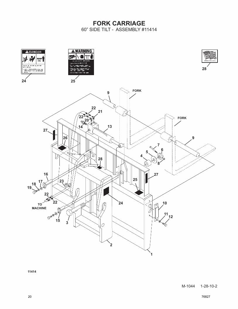
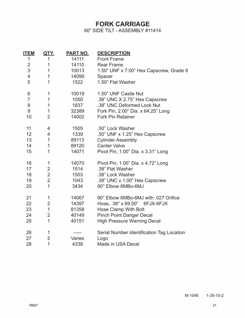
PARTS
The following section contains detailed diagrams and parts lists which include your attachment. Please use these diagrams and parts lists to locate replacement parts, prior to contacting the parts department.
When servicing your attachment, remember to use only original manufacturer replace-ment parts. Substitute parts may not meet the standards required for safe, dependable opera-tion.
To facilitate parts ordering, have the model and serial number of your product ready, to ensure that you receive the correct parts for your specific attachment.
The model and serial number for your attachment should be recorded in the space provided on the cover of this manual. This information may be obtained from the serial number identification plate located on your attachment. See the parts diagram for your attachment for the location.
NOTE: Most daily and emergency orders received by 2:00 P.M. will be shipped the same day received, with “Emergency-Machine-Down” orders receiving first priority.