MANUFACTURED BY County Hwy. A West P.O. Box 405 Dorchester, Wisconsin 54425-0405 Phone 715-654-5132 • FAX 715-654-5513 1-800-325-9103 www.meyermfg.com E-mail: [email protected]12/03 OPERATORS AND PARTS MANUAL NO. 03-2-SI DO NOT OPERATE EQUIPMENT UNTIL THIS MANUAL HAS BEEN READ AND UNDERSTOOD INDUSTRIAL SERIES TWIN EXPELLER SUPER SPREADER MODEL 7200 PATENTED U.S. PATENT NO. 5,368,236 5,501,404
MANUFACTURER’S WARRANTYI. The “Product Registration & Inspection Certificate” along with the original billing invoice “Owners Registration Form”
must be completed in full and promptly returned to Meyer Mfg. Corp. for this warranty to become both valid and
effective. All warranties on New Meyer Super Spreaders shall apply only to the original retail customer from an
authorized Meyer Mfg. Corp. dealership.
II. This warranty shall not apply to any Meyer Super Spreader which has been subjected to misuse, negligence,
alteration, accident, incorrect operating procedures, or which shall have been repaired with parts other than
those obtained through Meyer Mfg. Corp.
III. Meyer Mfg. Corp. warrants New Meyer Super Spreaders to be free from defects in material and workmanship under
recommended use and maintenance service, as stated in the Operator’s and Parts Manual," as follows:
A. Meyer Mfg. Corp. will repair or replace F.O.B. Dorchester, WI, as Meyer Mfg. Corp. elects, any part of a new
Meyer Super Spreader which is defective in material or workmanship:
1. Without charge for either parts or labor during the first (1) year from purchase date to the
original retail customer.
B. In addition to the above basic warranty, Meyer Mfg. Corp. will repair or replace F.O. B. Dorchester, WI as Meyer
Mfg. Corp. elects:
Ten (10) Years: After a period of (1) year, the spreader tank body is warranted against rust-through for an
additional period of (9) years. (Pro-Rated Parts Only). Parts included, front and rear end
panels, side panels, and auger trough.
IV. COMMERCIAL USE: Coverage as in paragraph III A1 ONLY, except warranty coverage is for (90) days for parts and
labor to the original commercial retail customer.
V. Repairs eligible for labor warranty must be made by Meyer Mfg. Corp. or an authorized Meyer dealership. The
original retail customer is responsible for the transportation of the super spreader to the dealership for warranty
service or for any service call expenses.
VI. Except as stated above, Meyer Mfg. Corp. shall not be liable for injuries or damages of any kind or nature, direct,
consequential, or contingent, to persons or property. This warranty does not extend to loss of crop or for any other
reasons.
VII. No person is authorized to give any other warranties or to assume any other obligation on Meyer Mfg. Corp.’s. behalf
unless made or assumed in writing by Meyer Mfg. Corp. This warranty is the sole and exclusive warranty which is
applicable in connection with the manufacture and sale of this product and Meyer Mfg. Corp.’s responsibility is
limited accordingly.
VIII. This warranty is effective on all sales of Meyer Super Spreaders made after January 1, 1992.
July 1, 2000
INTRODUCTIONCongratulations on your purchase of a new Meyer farm
equipment product. Undoubtedly you have given much
consideration to your purchase and we’re proud that you
have selected Meyer. Pride in craftsmanship, engineer-
ing and customer service have made Meyer products
the finest in the farm equipment industry today.
There is no substitute for quality. That is why thousands
of people like you have purchased Meyer farm equip-
ment. They felt it was the best equipment to serve their
farming needs, now and in years to come. We ask that
you follow our policy of “safety first,” and we strongly
suggest that you read through the owner’s manual be-
fore operating your Meyer farm equipment.
Meyer Manufacturing Corporation wants to thank you
for not compromising quality. We are determined to offer
excellence in customer service as well as provide you
with the very best value for your dollar.
REMEMBER:
FARM EQUIPMENT BUYERS
TRUST THE NAME MEYER!
Sincerely,
All Employees of
MEYER MANUFACTURING CORPORATION
Meyer Mfg. Corp. reserves the right to make improve-
ments in design, or changes in specifications at any
time, without incurring any obligation to owners of units
previously sold.
This supersedes all previous published instructions.
IMPORTANT:
At the front of this manual is a Product Registration and
Inspection Certificate. Be sure your dealer has com-
pleted this certificate and promptly forwarded a copy to
Meyer Mfg. to validate the manufacturer’s warranty. The
product model and serial number are recorded on this
certificate and below for proper identification of your
Meyer Industrial Spreader by your dealer and the manu-
facturer when ordering repair parts. The serial number
plate is found on the upper left front corner of the
spreader tank or stamped in the left front frame channel.
Model No. _____________________________
Serial No. _____________________________
Date of Purchase ______________________
At the back of this manual is the repair parts section. All
replacement parts are to be obtained from or ordered
through your Meyer dealership. When ordering repair
parts, refer to the parts section and give complete infor-
mation including quantity, correct part number, detailed
description and even Model No. and Serial No. of the
Meyer Industrial Spreader which needs repair parts.
Model 7200 -4-
NOTE: All references to right hand (RH), left hand (LH),
front and rear apply to the product as viewed from the
rear of the spreader.
Model 7200 -5-
SAFETY PRECAUTIONS
This symbol is used to call attention to instructions concerning personal safety. Be sure to observe
and follow these instructions. Take time to be careful!
WARNING: BEFORE ATTEMPTING TO OPERATE THIS SPREADER, READ AND STUDY THE
FOLLOWING SAFETY INFORMATION. IN ADDITION, MAKE SURE THAT EVERY INDIVIDUAL WHO
OPERATES OR WORKS WITH THE SPREADER, WHETHER FAMILY MEMBER OR EMPLOYEE, IS FAMILIAR
WITH THESE SAFETY PRECAUTIONS.
Require anyone who will operate this spreader to read and completely understand this Owner’s Manual. Givenecessary instructions!
DO NOT operate, service, inspect or otherwise handle this spreader until all operators have read this Owner’sManual and have been properly trained in the intended usage of the spreader.
Do not allow minors (children) or inexperienced persons to operate this spreader.
If the spreader becomes clogged, shut off the tractor engine and allow all mechanisms to stop. Disconnect PTO shaftand hydraulic hoses (relieve hydraulic pressure). Then, clean or work on the spreader as required.
Always shut off power and disconnect PTO drive shaft and unhook hydraulic hoses (relieve hydraulic pressure) fromtractor to prevent accidental startup or unexpected movement before working on machine.
Do not clean, adjust, or lubricate while spreader is in motion.
Make sure all hydraulic fittings are tight and that all hoses are in good condition. Hydraulic fluid escaping underpressure can have sufficient force to penetrate skin and cause serious injury. Never investigate for hydraulic leaks byusing a part of the body to feel for escaping fluid.
Inspect when first delivered and regularly thereafter; that all connections and bolts are tight and secure before operating.
Know how to stop the spreader before starting it!
Do not operate until all shields, covers, and guards are in place.
Make certain everyone is clear of the spreader before applying power.
Keep hands, feet and clothing away from moving parts. Loose or floppy clothing should not be worn by the operator.
Stay well clear of the spreader’s rear discharge spinners while operating.
Do not step up on any part of the spreader at any time. Do not use PTO guard as a step.
Do not step over the power take-off shaft. Stay clear of the PTO at all times.
Never operate PTO above normal 540 or 1000 RPM rating. Tractors PTO MUST match implement PTO.
Use only properly rated tires.
Do not tow at speeds in excess of 20 MPH when transporting this spreader. Never exceed a safe travel speed.
Observe all applicable traffic laws when transporting on public roadways (where legal to do so). Check local laws forall highway lighting and marking requirements.
WHEN TOWING THE SPREADER ON PUBLIC ROADS A Safety Chain of sufficient strength to support, along theline of travel, the gross weight (See Maximum Load Weight Chart / Transporting Section) of the spreader must beused. A safety chain should be attached per diagram in Transporting Section.
Always install a SMV emblem on this spreader for transporting on roadways and keep the emblem clean and bright.
MEYER MFG. CORP. PROVIDES GUARDS FOR EXPOSED MOVING PARTS FOR THE OPERATOR’S
PROTECTION; HOWEVER, SOME AREAS CANNOT BE GUARDED OR SHIELDED IN ORDER TO ASSURE
PROPER OPERATION. THE OPERATOR’S MANUAL AND DECALS ON THE MACHINE ITSELF WARN YOU
OF DANGERS AND MUST BE READ AND OBSERVED CLOSELY.
STUDY THE ABOVE SAFETY RULESFAILURE TO HEED MAY RESULT IN SERIOUS PERSONAL INJURY OR DEATH.
SAFETY FIRSTA brief definition of signal words that may be used in this
manual is as follows:
DANGER Indicates an imminently hazardous sit-
uation which, if not avoided, WILL result in serious injury
or death.
WARNING Indicates a potentially hazardous
situation which, if not avoided, COULD result in death or
serious injury, and includes hazards that are exposed
when guards are removed.
CAUTION Indicates a potentially hazardous
situation which, if not avoided, MAY result in minor or
moderate injury. It is also used to alert against unsafe
practices.
Model 7200 -6-
AK
E
FJ
A
A
A
CLocated UnderShield
D G
AB
I
B
A
B
H
E
Located UnderShield
CLocated UnderShields
CLocated UnderShields
L
CAUTION: READ ALL DECALS ON THE SPREADER AND IN THIS MANUAL. KEEP THESE DECALS CLEAN AND
REPLACE ANY LOST OR DESTROYED DECALS. BECOME FAMILIAR WITH ALL TRACTOR AND SPREADER CONTROLS.
SAFETY FIRST
The Meyer Super Spreader is manufactured with operator safety in mind. Located on the manure spreader are vari-
ous decals to aid in operation and warn of danger or caution areas. Pay close attention to all decals on the spreader.
DO NOT REMOVE ANY DECALS. IF DECALS ARE LOST, DAMAGED OR IF MANURE SPREADER
IS REPAINTED, REPLACE DECALS. REMEMBER: DECALS ARE FOR YOUR PROTECTION AND INFORMA-
TION.
Model 7200 -7-
DECAL A. PART NO. 46-0001-5
DECAL E. PART NO. 46-0001-4
DECAL C. PART NO. 46-0001-26
DECAL H. PART NO.
46-3600-8
DECAL I. PART NO. 46-3600-1
DECAL B. PART NO. 46-3600-9
DECAL D. PART NO. 46-0001-13
DECAL G. PART NO. 46-0004-2
DECAL F. PART NO. 46-3600-6
DECAL J. PART NO. 46-0001-22
DECAL K. PART NO. 46-0001-35
CAUTIONINDUSTRIAL SERIES GEAR BOXES
THE ONE -- RIGHT REAR, CORNER GEAR BOX USE:
#80-90 wt. GEAR LUBE OIL ONLY.
THE TWO -- SPINNER/EXPELLER GEAR BOXES USE:
SEMI-FLUID, EP LITHIUM BASE, GEAR GREASE.
DECAL L. PART NO. 46-5570-3
46-5570-3
CAUTION: READ ALL DECALS ON THE SPREADER AND IN THIS MANUAL. KEEP THESE DECALS CLEAN AND
REPLACE ANY LOST OR DESTROYED DECALS. BECOME FAMILIAR WITH ALL TRACTOR AND SPREADER CONTROLS.
PRE-OPERATION
WARNING: BEFORE OPERATING, READ THIS OWNERS MANUAL COMPLETELY. PAY
PARTICULAR ATTENTION TO THE “SAFETY PRECAUTION” AND “SAFETY FIRST” PAGES. READ ALL
SAFETY MESSAGES HIGHLIGHTED BY “SAFETY ALERT SYMBOLS” THROUGHOUT THE MANUAL.
This spreader can be operated with 540 or 1000 RPM
PTO. The hitch of the spreader is designed for a stan-
dard tractor drawbar. Adjust the drawbar at 13 to 20
inches above the ground. Extend or shorten the drawbar
so horizontal distance from end of tractor PTO shaft to
center of the hitch pin hole is 16 inches. Secure the
drawbar so that the hitch pin hole is located directly be-
low the PTO drive line. See figure 1 for location of stan-
dard measurements.
An improperly located hitch point may cause damage to
the universal joints of the PTO drive shaft. Conforming
to the standard 16" drawbar & PTO relationship will en-
sure that the PTO drive shaft will not become over-ex-
tended.
DANGER: DO NOT OPERATE WITHOUT
PTO GUARD ON SPREADER AND ON TRACTOR.
MAINTAIN PTO DRIVE SHAFT GUARD TUBES IN
OPERATING CONDITION. REPLACE THEM IF DAM-
AGED AND NOT TURNING FREELY. FAILURE TO
HEED MAY RESULT IN SERIOUS PERSONAL IN-
JURY OR DEATH.
WARNING: INSPECT REGULARLY THAT
ALL CONNECTIONS AND BOLTS ARE TIGHT AND
SECURE BEFORE OPERATING. FAILURE TO HEED
MAY RESULT IN SERIOUS PERSONAL INJURY OR
DEATH.
Check for proper assembly and adjustment and make
sure that all bolts are tightened. Securely retighten after
a few hours of operation, as bolts can loosen up on new
machinery. Check wheel lug nuts upon delivery and pe-
riodically thereafter. Lug nuts should be tightened at
250-265 ft./lbs. of torque. Check the tires and inflate to
the recommended pressure. See chart on page 55.
Inspect all adjustments on the spreader to be sure they
are proper and to provide maximum performance. Lubri-
cate the spreader completely if it is required and check
the level of oil in the right rear corner gear box, and the
gear grease in the expeller gear boxes.
WARNING: DO NOT OPERATE WITHOUT
ALL SHIELDS, GUARDS AND COVERS INSTALLED.
FAILURE TO HEED MAY RESULT IN SERIOUS PER-
SONAL INJURY OR DEATH.
Fasten the spreader hitch to the tractor drawbar with a
hitch pin that cannot bounce out. Use a 1-5/16” to 1-3/8”
diameter hitch pin to pull spreader.
Remove the weight from the jack (jack is not to be used
when spreader is loaded). Remove the jack from
square mount tube and move to the transport storage
tube on the left front side of the frame channel. Store in
a horizontal position.
Before operation and after hitching the tractor to the
spreader, connect the PTO drive shaft to the tractor.
Slide spring loaded locking collar on PTO yoke rearward,
and slide yoke onto the tractor PTO shaft. Release spring
loaded collar. Be sure pins fall into groove of tractor PTO
shaft and collar snaps forward into locking position.
CAUTION: DO NOT USE A STEEL HAMMER
TO AID IN JOINING PTO PARTS.
Route hydraulic hoses through the hose support rod
which is mounted to the hitch frame, figure 2. Connect
the hydraulic hoses for the flow control rear gate to the
tractor’s double acting valve hydraulic system. Move the
tractor hydraulic controls to observe proper flow gate
operation. If the controls operate the gate in opposite di-
rections to what you expect, reverse the hydraulic hose
connections at the tractor.
Model 7200 -8-
FIGURE 1. TRACTOR DRAWBAR & PTO
SPECIFICATION
WARNING: HYDRAULIC FLUID ESCAPING
UNDER PRESSURE CAN HAVE SUFFICIENT
FORCE TO PENETRATE SKIN. KEEP ALL HOSES
AND CONNECTIONS IN GOOD SERVICEABLE CON-
DITION. FAILURE TO HEED MAY RESULT IN SERI-
OUS PERSONAL INJURY OR DEATH.
Before loading spreader, slowly engage the tractor PTO
and operate machine at idle speed for several minutes
to insure the spreader is lubricated and operating prop-
erly.
TRANSPORTING
TRACTOR TOWING SIZE REQUIREMENTS
Use the following chart for calculating the minimum trac-
tor weight.
MODEL SPREADER EMPTYWEIGHT + LOAD = GW
MINIMUMTRACTORWEIGHT UP TO20 MPH
SV2636 6,100 + _____ = _____ 2/3 of spreadergross weight
SV3245 7,640 + _____ = _____ 2/3 of spreadergross weight
SV3954 8,650 + _____ = _____ 2/3 of spreadergross weight
SI7200 11,445 + _____ = _____ 2/3 of spreadergross weight
SI8500 18,140 + _____ = _____ 2/3 of spreadergross weight
MATERIAL ESTIMATED WEIGHT PER CUBIC FOOT
MATERIAL LBS / CU. FT.
LIME SLUDGE 110-115 LBS.
DRY FEEDLOT MANURE 63-65 LBS.
CHICKEN LITTER 63-65 LBS.
CAKE SLUDGE 62-65 LBS.
SEMI-SOLID MANURE 58-60 LBS.
PEN PACKED MANURE 30-35 LBS.
LIQUID MANURE 63-65 LBS.
SOURCE: ASAE
NOTE: HEAPED LOADS HAVE SIGNIFICANTLY
HIGHER CAPACITIES
Check that the flow control rear gate is completely
closed. It is unlawful to allow slurry to splash or leak onto
public roads.
WARNING: DO NOT TOW AT SPEEDS
GREATER THAN 20 MPH. FAILURE TO HEED MAY
RESULT IN SERIOUS PERSONAL INJURY OR
DEATH.
Operating speed is dictated by the terrain over which
you are traveling. Always use caution. Avoid traveling
on slopes or hills that are unsafe.
WARNING: OBSERVE ALL APPLICABLE
TRAFFIC LAWS WHEN TRANSPORTING ON PUB-
LIC ROADWAYS. CHECK LOCAL LAWS FOR ALL
HIGHWAY LIGHTING AND MARKING REQUIRE-
MENTS.
Model 7200 -9-
FIGURE 2. SPREADER HOOKUP
HOSE
BRACKET
PTO
SHAFT
JACK
STORAGE
HUB
HITCH
JACK
MAXIMUM SPREADER LOAD WEIGHTS
Model 2636 3245T 3954T 7200T 8500T
Maximum Gross Weight (Pounds) 12,000 24,000 32,000 43,445 56,140
Total Net Weight (Pounds) 6,100 7,640 8,650 11,445 18,140
Cubic Foot Capacity** 181 227 272 466 562
Capacity in Gallons 1,355 1,694 2,033 3,492 4,200
**Struck capacity, heaped loads have significantly higher capacities
WARNING: INSTALL A SMV EMBLEM ON
REAR OF SPREADER FOR TRANSPORTING ON
ROADWAYS AND KEEP THIS EMBLEM CLEAN AND
BRIGHT. FAILURE TO HEED MAY RESULT IN SERI-
OUS PERSONAL INJURY OR DEATH.
If you will travel on public roads and it is legal to do so,
you must know all rules governing such operation. This
will include lighting and brake requirements in addition
to traffic rules. You may also be required to install a
safety chain device on the spreader.
Check for traffic constantly. Be sure you can see that no
one is attempting to pass you and that all traffic is suffi-
ciently clear from you before making any turns.
OPTIONAL TRUCK MOUNT
SPREADERS
Depending on the make and model of the truck it may be
necessary to install a light converter (MEYER PART
#56-0028). Converter will allow signal lights and brake
lights to operate according to DOT lighting standard.
Call factory for more information.
USE OF SAFETY CHAIN
CAUTION: A SAFETY CHAIN MUST BE
INSTALLED TO RETAIN THE CONNECTION
BETWEEN TRACTOR (OR OTHER TOWING
VEHICLE) AND SPREADER WHENEVER
TRAVELING ON PUBLIC ROADS IN CASE THE
HITCH CONNECTION WOULD SEPARATE. A
SUGGESTED ATTACHMENT IS ILLUSTRATED ON
FIGURE 3.
The chain must be strong enough to hold the weight of
the loaded spreader (See table on page 9). If using a
grab hook at the end(s) of the chain to secure the chain
to itself, a hook latch must be installed.
The length of the safety chain is not to be any longer
than necessary to turn without interference. If any chain
links or attachment hardware are broken or stretched,
repair before using. Store chain so it does not corrode or
become damaged. Do not use this chain for other
implements because the strength and length of the
chain may not be adequate. Identify this chain for use on
this particular spreader. Do not use the intermediate
support as the attaching point.
FREEZING WEATHER OPERATION
Allow spreader to completely empty last of manure con-
tents and disengage tractor PTO. Shut off tractor, re-
move the ignition key and allow all movement to stop
before attempting to clean the spreader.
Model 7200 -10-
FIGURE 3. SAFETY CHAIN INSTALLATION
TOWING MACHINE
ATTACHING POINT
HOOK W/ HOOK
LATCH
SAFETY CHAIN LOOP.
INTERMEDIATE SUPPORT
WARNING: DO NOT CLEAN, ADJUST OR
LUBRICATE WHILE SPREADER IS IN MOTION.
FAILURE TO HEED MAY RESULT IN SERIOUS PER-
SONAL INJURY OR DEATH.
Scrape clean any remaining manure from inside the rear
of spreader. Clean all manure from ends of augers, flow
control rear gate and spinners.
WARNING: MAKE CERTAIN EVERYONE IS
CLEAR OF THE SPREADER BEFORE APPLYING
POWER. FAILURE TO HEED MAY RESULT IN SERI-
OUS PERSONAL INJURY OR DEATH.
Slowly engage the PTO. Operate the spreader several
minutes to clean manure scrapings and to allow any re-
maining manure and the spreader to freeze dry. Hydrau-
lically run the flow control rear gate up and down to
clean gate slide guides. Park spreader with flow control
rear gate approximately halfway open.
Before loading in freezing weather, make sure augers
and spinners are free to rotate, and the flow control rear
gate moves freely up and down.
DANGER: KEEP AWAY AND KEEP
OTHERS CLEAR OF ROTATING SPINNERS AT
REAR OF SPREADER. SERIOUS INJURY OR AM-
PUTATION COULD RESULT. FAILURE TO HEED
MAY RESULT IN PERSONAL INJURY OR DEATH.
Model 7200 -11-
OPERATIONLOADING
CAUTION: TO PREVENT DAMAGE TO AU-
GERS, SPINNERS, AND DRIVE LINES, FOREIGN
OBJECTS (STONES, CONCRETE, TIMBER, METAL
OR LARGE FROZEN CHUNKS OF MANURE)
SHOULD NEVER BE LOADED INTO THE
SPREADER.
DANGER: NEVER ENTER THE SPREADER
BOX FOR ANY REASON WITHOUT FIRST DISCON-
NECTING PTO SHAFT FROM TRACTOR. DO NOT
ALLOW OTHERS IN THE BOX. ROTATING AUGERS
CAN CRUSH AND DISMEMBER. FAILURE TO HEED
MAY RESULT IN SERIOUS PERSONAL INJURY OR
DEATH.
CAUTION: DO NOT USE JACK EXCEPT
WHEN SPREADER IS EMPTY. JACK WILL NOT
SUPPORT ADDED WEIGHT. UNBALANCED
WEIGHT MAY RESULT IN UNEXPECTED “TIP UP”
OF SPREADER.
Before loading, especially in freezing weather, make
sure the augers and spinners are free to rotate and the
flow control rear gate moves freely up and down.
Check and be sure that the flow control rear gate is
completely closed before loading.
When the spreader is parked for loading, shift the tractor
to neutral or park and set the brakes. The moisture con-
tent of the manure will determine how full the spreader
can be loaded so that no manure spills out.
You will probably be able to load solid manure at least
level with the top of the box while semi-liquid and liquid
manure will have to be less than full in the spreader box.
It is unlawful to allow manure to splash or leak onto pub-
lic roads.
A liquid manure kit is available for installation around the
top of the box on your spreader which will aid in the con-
tainment of liquids.
UNLOADING
WARNING: MAKE CERTAIN EVERYONE IS
CLEAR OF SPREADER BEFORE APPLYING
POWER. FAILURE TO HEED MAY RESULT IN
SERIOUS PERSONAL INJURY OF DEATH.
DANGER: KEEP AWAY AND KEEP OTHERS
CLEAR OF ROTATING SPINNERS AT REAR OF
SPREADER. SERIOUS INJURY OR AMPUTATION
COULD RESULT. FAILURE TO HEED MAY RESULT
IN SERIOUS PERSONAL INJURY OF DEATH.
When you are ready to begin spreading application on
the field, open the hydraulic flow control rear gate and
slowly engage the tractor PTO clutch. This can be done
while traveling forward to avoid a heavier application of
liquid manure at the edge of the field than desired.
For liquid and semi-liquid manure, the application rate
can be controlled by the amount the flow control rear
gate is opened. The gate indicator on the front of the box
will provide a ready reference for the amount of opening.
For solid manure (dry, pen-packed or manure
containing long straw or hay) the flow control rear gate
MUST be completely open since this material is not free
flowing.
VERY IMPORTANT: THIS MACHINE IS NOT
INTENDED TO BE A BALE GRINDER, HAY
CHOPPER OR BEDDING MACHINE. LONG HAY OR
STRAW MUST CONTAIN MANURE IN ORDER TO BE
SPREAD. FAILURE TO COMPLY MAY DAMAGE THE
DRIVETRAIN AND VOID THE WARRANTY.
Model 7200 -12-
FIGURE 4. FLOW CONTROL GATE
INDICATOR
The rear spinners have been designed and tested to
provide the best spread pattern for most liquids and
semi solid manure. However, the pattern will vary for
each specific condition. The factors that contribute most
to differing patterns will be moisture content and the
amount and length of bedding material. For most typical
conditions, the spread pattern should be uniform and
about 15 ft. wide. When this is the case, plan your
spreading patterns so you do not have to travel over pre-
viously spread manure which will be slippery, resulting
in poor traction. Traction on wet grass is also poor.
When the resulting pattern may require that you over-
lap during spreading, use precautions on slopes and
hills where you could experience a loss of traction by
traveling over ground with previously spread manure.
NOTE: Further control of the application rate is possible
by the relationship of tractor engine speed to ground
speed (transmission gear selection). For optimum, trou-
ble-free performance it is recommended to operate at or
near engine PTO speed.
When the spreader is empty, idle the tractor and stop
the PTO. Close the flow control rear gate.
WARNING: NEVER OPERATE PTO ABOVE
ITS NORMAL 540 or 1000 RPM RATING. TRAC-
TOR’S PTO MUST MATCH IMPLEMENT PTO.
NOTE: Failure to idle the tractor before disengaging the
PTO will cause roller chain over-running and damage to
the chain tighteners.
NOTE: Maximum life of the PTO shaft universal joints
will result if you stop the PTO while making turns at the
end of the field.
CAUTION: DO NOT EXCEED THE MAXI-
MUM 80� TURNING ANGLE ON THE CONSTANT VE-
LOCITY PTO DRIVELINE. EXCEEDING THE
TURNING ANGLE WILL DAMAGE THE CONSTANT
VELOCITY “CENTER HOUSING” AND WILL EXERT
EXCESSIVE PRESSURES ON THE PTO INPUT
CENTER SHAFT AND RELATED BEARINGS.
SHEAR SPROCKET INSTRUCTIONS
The Meyer Spreader you have received has been
equipped with a shear sprocket design on the main au-
ger drive sprockets. The augers are being driven by two
allen head grade 8 bolts. The design is such that if the
bolts are sheared another set of holes to install new
shear bolts will always be accessible without turning
over the machine.
DANGER: AT NO TIME SHOULD INSTALLA-
TION BE DONE WITH ANYONE ON THE TRACTOR.
SHUT THE TRACTOR OFF, REMOVE THE KEY AND
DISCONNECT THE DRIVE LINE BEFORE DOING
ANY SERVICE ON THIS MACHINE. SERIOUS IN-
JURY OR DEATH MAY OCCUR IF SAFETY IS NOT
FOLLOWED.
The plate sprocket is set up with the initial drive bolts
being 1/2” diameter. An extra set of holes for 7/16”, 9/16”
and 5/8” (dependent on age of sprocket) drive bolts are
located on the sprocket if needed. If the 1/2” bolts shear,
replace with the same 1/2” diameter bolts after
obstruction is removed. DO NOT JUMP UP TO THE
NEXT SIZE BOLT. Install the new bolts in the proper
way as to drive off of the head of the bolt, not the nut.
If a second shear has happened without obstruction in
the auger, install the next larger size shear bolt. As the
shear bolt size is increased the protection on the ma-
chine is going to decrease. The potential for equipment
damage is greater. Order replacement bolts and nuts
from the chart below. Sizes vary depending on sprocket.
Match to holes in sprocket.
Part # Description
831-4420-1.75 7/16-20x1-3/4” Allen Head Cap Bolt
884-4420 7/16-20 Top Locknut Grade 8
831-5020-1.75 ½-20x1-3/4” Allen Head Cap Bolt
884-5020 ½-20 Top Locknut Grade 8
831-5618-1.75 9/16-20x1-3/4” Allen Head Cap Bolt
884-5618 9/16-20 Top Locknut Grade 8
831-6318-1.75 5/8-18x1-3/4” Allen Head Cap Bolt
884-6318 5/8-18 Top Locknut Grade 8
910-0100 140B35 Shear Sprocket Assembly
Complete
Model 7200 -13-
STORAGE AFTER USE
WARNING: DISCONNECT PTO DRIVE
SHAFT AND HYDRAULIC HOSES BEFORE
CLEANING, ADJUSTING, OR SERVICING THIS MA-
CHINE. FAILURE TO HEED MAY RESULT IN SERI-
OUS PERSONAL INJURY OR DEATH.
Before storing this spreader for an extended period of
time perform the following:
Allow the spreader to completely clean out the last load.
Thoroughly hose off all manure from the outside of the
spreader and the inside of the box, particularly getting
the flow control rear gate mechanism clean. The wash
water can be drained into your manure storage pit, or if
the gate is left closed, the water can be spread on the
field. After cleaning, completely lubricate the entire
spreader to exclude moisture from bearings and to pre-
vent condensation from forming during storage. See
“Lubrication” pages 20 and 21.
Oil the roller chains by running the spreader at idle
speed while opening the rear gate to activate the auto-
matic oiler system. It is also a good time to inspect all ad-
justments and check for parts that need repair or
replacement. Performing these tasks now will guaran-
tee that the spreader is ready for use at the beginning of
the next season.
Model 7200 -14-
PTO DRIVELINE
WARNING: BEFORE ATTEMPTING TO
OPERATE THIS SPREADER, READ AND STUDY
ALL SAFETY INFORMATION. IN ADDITION, MAKE
SURE THAT EVERY INDIVIDUAL WHO OPERATES
OR WORKS WITH THE SPREADER, WHETHER
FAMILY MEMBER OR EMPLOYEE, IS FAMILIAR
WITH THESE SAFETY PRECAUTIONS.
WARNING: DISCONNECT PTO DRIVE SHAFT
AND HYDRAULIC HOSES (RELIEVE HYDRAULIC
PRESSURE) BEFORE CLEANING, ADJUSTING,
LUBRICATING OR SERVICING THIS SPREADER.
FAILURE TO HEED MAY RESULT IN SERIOUS
PERSONAL INJURY OR DEATH.
The Meyer 7200 Industrial Series Spreader is equipped
with a cutout type clutch on the implement half of the
PTO driveline. The clutch is designed to limit the
amount of torque transferred to the machine through the
driveline. If excessive torque is developed the clutch will
disengage. A loud ratcheting sound will be heard and
the transfer of power to the machine will be disrupted.
To reengage the machine simply shut down the PTO
and allow the driveline to come to a stop. The PTO can
then be reengaged to restart the spreader. The cutout
clutch will either reengage upon shut down of the PTO
or just before it comes to a complete stop.
The cutout clutch will disengage if start up is done in an
abrupt or reckless manner. It also will disengage from
foreign materials entering the spinner area of the
spreader. It may also be possible to disengage the
clutch by overloading or flooding the spinners with free
flowing or liquid manure. If PTO clutch fails to reengage
it will be necessary to remove the foreign object from the
spreader before restarting. THERE IS NO FIELD
ADJUSTMENT ON THE CUTOUT CLUTCH.
DANGER: NEVER ENTER THE SPREADER
BOX FOR ANY REASON WITHOUT FIRST
STOPPING THE TRACTOR, SHUTTING THE
TRACTOR OFF AND REMOVING THE KEY,
SETTING THE PARKING BRAKE AND
DISCONNECTING THE PTO DRIVELINE FROM THE
TRACTOR. DO NOT ALLOW OTHERS IN THE BOX.
ROTATING AUGERS CAN CRUSH AND
DISMEMBER. FAILURE TO HEED MAY RESULT IN
SERIOUS PERSONAL INJURY OR DEATH.
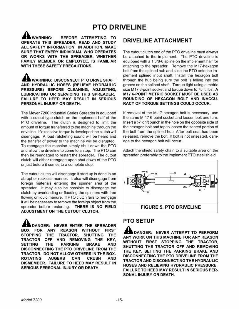
DRIVELINE ATTACHMENT
The cutout clutch end of the PTO driveline must always
be attached to the implement. The PTO driveline is
equipped with a 1 3/8-6 spline on the implement half for
attaching to the spreader. Remove the M17-hexagon
bolt from the splined hub and slide the PTO onto the im-
plement splined input shaft. Install the hexagon bolt
through the hub being sure the bolt is falling into the
groove on the splined shaft. Torque tight using a metric
size M17 6-point socket and torque down to 75 ft. lbs. A
M17 6-POINT METRIC SOCKET MUST BE USED AS
ROUNDING OF HEXAGON BOLT AND INACCU-
RACY OF TORQUE SETTINGS COULD OCCUR.
If removal of the M-17 hexagon bolt is necessary, use
the same M-17 6-point socket and loosen bolt one turn.
Insert a ¼” drift punch in the hole on the opposite side of
the hexagon bolt and tap to loosen the seated portion of
the bolt from the splined hub. After bolt seat has been
released, remove the bolt. If bolt is not unseated, dam-
age to the hexagon bolt will occur.
Attach the shield safety chain to a suitable area on the
spreader, preferably to the implement PTO steel shield.
PTO SETUP
DANGER: NEVER ATTEMPT TO PERFORM
ANY WORK ON THIS MACHINE FOR ANY REASON
WITHOUT FIRST STOPPING THE TRACTOR,
SHUTTING THE TRACTOR OFF AND REMOVING
THE KEY, SETTING THE PARKING BRAKE AND
DISCONNECTING THE PTO DRIVELINE FROM THE
TRACTOR AND DISCONNECTING THE HYDRAULIC
HOSES AND RELIEVING HYDRAULIC PRESSURE.
FAILURE TO HEED MAY RESULT IN SERIOUS PER-
SONAL INJURY OR DEATH.
Model 7200 -15-
FIGURE 5. PTO DRIVELINE
Adjust the drawbar at 16-20” above the ground. Extend
or shorten the drawbar so horizontal distance from end
of tractor PTO shaft to center of hitch pin hole is 16” for
1000 RPM 1-3/8-21 spline, (14” for 540 RPM 1-3/8-6
spline) (20” for 1000 RPM 1-3/4-20 spline). Secure the
drawbar so the hitch pin hole is located directly below
the PTO driveline. PTO adapters are not recommended
as damage to the driveline may occur. A hitch pin with a
minimum diameter of 1-5/16” and bottom retaining pin is
recommended.
AN IMPROPERLY LOCATED HITCH POINT MAY
CAUSE DAMAGE TO THE UNIVERSAL JOINTS OF
THE PTO DRIVE SHAFT. CONFORMING TO THE
STANDARD 16” DRAWBAR (1000 RPM) AND PTO
RELATIONSHIP WILL ENSURE THAT THE PTO
DRIVESHAFT WILL NOT BECOME OVER EX-
TENDED. WITH INITIAL HOOK-UP TO YOUR NEW
MEYER SPREADER TEST PTO TRAVEL BY
TURNING EQUIPMENT IN BOTH DIRECTIONS OB-
SERVING THE MINIMUM AND MAXIMUM TRAVEL
DIMENSIONS AS SHOWN PER DRAWING ON FIG-
URE 6.
LUBRICATION
LUBRICATIONA high quality Lithium Base Grease should be used
PRIOR TO USE
A. Using the CV Zerk (Key #2) place 20 pumps of
grease into the CV center housing. This should
be done with the driveline / CV as straight as
possible.
B. Slowly articulate the double joint through its
maximum joint angle several times.
C. Return the CV joint to its straight position and
insert additional grease into the CV Zerk (Key
#2) until grease is evident around the housing
and center sliding disk.
NORMAL OPERATION
A. Lubricate the following items after every eight
(8) hours of operation. If short rows and
frequent turning or other demanding conditions
exist, lubricate at four (4) hour intervals.
1. Cross and bearings (Key #1)-Add grease
until it is purged around the seals
2. CV center housing (Key #2)-Add grease
until it is evident around the center sliding
disk.
3. Telescoping members (Key #3)-Add
grease until it adequately covers the
sliding members. Take apart
occasionally to make sure adequate
lubrication is being added.
4. Shield bearings (Key #4)-Add 2-3 pumps.
FAILURE TO FREQUENTLY GREASE THE CV
CENTER HOUSING AND TELESCOPING MEMBERS
WILL REDUCE THE LIFE OF THE CV.
MAINTENANCE INFORMATION
It is extremely important to follow the maintenance
guidelines. If telescoping members become hard to
slide during normal operation, it is recommended the
shaft be taken apart, cleaned with solvent and recoated
with grease before re-assembling. As a minimum it is
important this be done after each season of use.
Model 7200 -16-
FIGURE 6. PTO DRIVELINE
ADJUSTMENTS
WARNING: DISCONNECT PTO DRIVE SHAFT AND HYDRAULIC HOSES (RELIEVE HYDRAULIC
PRESSURE) BEFORE CLEANING, ADJUSTING, LUBRICATING OR SERVICING THIS SPREADER. FAILURE
TO HEED MAY RESULT IN SERIOUS PERSONAL INJURY OR DEATH.
FRONT DRIVE ROLLER CHAINSThere are six roller chain drives located at the front of the spreader. Regularly check that all tensioning springs are inserviceable condition for automatic roller chain tightening. Manually adjust spring tensioners (as needed) by turningdouble locknuts on all tensioning bolt/idler assemblies. Proper roller chain tension is when 1/4" to ½" deflectionoccurs on the slack side of the chain. Regularly re-check all roller chain tensions. Keep all roller chains tight at alltimes! For clarity purposes, the following illustrations detail each roller chain reduction separately.
NOTE: The side bars of the roller chains will wear into the idler nylon rollers up to the rollers of the roller chain forminggrooves. These grooves will serve as a guide when the roller chain loosens due to normal use. From this point on,after tightening, the idler nylon rollers should run for hundreds of hours without any noticeable wear.
Model 7200 -17-
FIGURE 7. FIRST CHAIN DRIVE
RH TOP
SPROCKET
ROLLER
CHAIN
IDLER NYLON
PTO
INPUT
SPRING LOADED
ADJUSTER
The first chain drive (PTO input shaft to the large RH top
sprocket, figure 7) is automatically tensioned by a spring
loaded idler nylon roller. The extension spring should
extend 2” from its neutral 5” total length.
Manual adjustment for the automatic tensioning idler,
nylon roller assembly is located at the left rear of the
spreader’s front bearing mounting plate.
The second chain drive (large RH top sprocket to the
large LH top sprocket, figure 8) is automatically
tensioned by a spring loaded idler nylon roller. The
extension spring should extend 2“ from its neutral 5"
total length.
Manual adjustment for the automatic tensioning idler,
nylon roller assembly is located at the left rear of the
spreader’s front bearing mounting plate.
FIGURE 8. SECOND CHAIN DRIVE
IDLER NYLON
ROLLER
ROLLER CHAIN
LH TOP SPROCKET
SPRING LOADED
ADJUSTER
Model 7200 -18-
FIGURE 9 . THIRD CHAIN DRIVE
TENSIONER
ARM
ROLLER CHAIN IDLER NYLON
ROLLER
FIGURE 10. RH AUGER CHAIN DRIVE
SPRING LOADED
ADJUSTER
IDLER NYLON
ROLLER
ROLLERCHAIN
RH AUGER
SPROCKET
FIGURE 11. LH & THIRD AUGER CHAIN
DRIVE
IDLER
SPROCKET
LH AUGER
SPROCKET
ROLLER
CHAIN
COMPRESSION
SPRING
IDLER SPROCKET
ADJUSTER BOLT
THIRDAUGERDRIVE
SPROCKET
The RH auger chain drive, figure 10, is automatically
tensioned by a spring loaded idler nylon roller. The
extension spring should extend 3/4" from its neutral 4"
total length.
Manual adjustment for the automatic tensioning idler,
nylon roller assembly is located at the right front lower
corner of the spreader tank.
The third chain drive is automatically tensioned by a
spring-loaded nylon idler roller. The extension spring
should extend 3/4” from its neutral 4” total length. See
figure 9.
Manual adjustment for the automatic tensioning idler,
nylon roller assembly is located on the extended arm of
the mount channel assembly.
The LH and third auger chain drive is automatically
tensioned by a spring loaded heavy compression
spring and sliding idler sprocket assembly, figure 11.
The heavy compression spring should be compressed
to 3-1/2" to 4" in length.
Manual adjuster bolt for the automatic tensioning idler
assembly is located at the right front upper corner of the
spreader tank.
SPINNER MATERIAL GUIDESRegularly inspect and adjust two spinner material
guides located at both the left rear and right rear of the
spreader. Create a 1/4-1/2” clearance between material
guides and spinner teeth, figure 13. Maintain the recom-
mended clearances for maximum spreading pattern.
Adjust to prevent excessive manure build-up on mate-
rial guide inner surfaces. Adjust to prevent manure
chunks or foreign object lodging between material
guides and spinner teeth.
NOTE: Excessive lodging can cause premature spinner
tooth wear, “bent-over” or even breakage.
SPRING LOADED MATERIAL GUIDE
ADJUSTMENTAdjustments for the 1/4-1/2” clearance of each material
guide to spinner tooth is made by tightening or loosen-
ing the 1” nut on the material guide spring linkage shaft
assembly. Tighten nut to increase clearance and loosen
nut to decrease clearance between the material guides
and spinner teeth. Once recommended clearance is ob-
tained turn spinners over by hand in the direction by
which the spreader would turn to check clearance. Do
not turn in the opposite direction as front chain tightener
damage could occur.
SHEAR ARM MATERIAL GUIDE
ADJUSTMENTAdjustment for the1/4-1/2” clearance of each material
guide to spinner tooth is made by loosening the jam nut
on the linkage arm and turning the linkage arm to either
move the guide in closer or out farther from the spinner
teeth. After adjustment has been made for the 1/4-1/2”
clearance retighten the jam nut to hold the material
guide in place. Once recommended clearance is ob-
tained turn spinners over by hand in the direction by
which the spreader would turn to check clearance. Do
not turn in the opposite direction as front chain tightener
damage could occur. If foreign objects enter the spinner
area the front pivot bolt on the shear arm is designed to
shear. The extension spring will pull the material guide
away from the spinner until the shear bolt is replaced.
The ½-13x3” grade 5 replacement machine bolts are
stored on the left side plate for the gearbox mount
channel. For replacement install with ½” flat washer on
top of shear eye and on bottom of block and tighten ny-
lon locknut firmly.
Model 7200 -19-
FIGURE 12. SIDE SHAFT CHAIN DRIVE
SIDE LINE SHAFT
DRIVE SPROCKET
PTO INPUT
SPRING LOADED
ADJUSTER
IDLER NYLON
ROLLER
FIGURE 13. MATERIAL GUIDE
CLEARANCE
The side shaft chain drive (PTO input shaft to the side
line shaft drive sprocket, figure 12) is automatically
tensioned by a spring loaded idler nylon roller. The
extension spring should extend 2" from its neutral 5"
total length.
Manual adjustment for the automatic tensioning idler,
nylon roller assembly is located at the right rear of the
spreader’s front bearing mounting plate.
1/4”-1/2”
LUBRICATION
WARNING: DISCONNECT PTO DRIVE SHAFT AND HYDRAULIC HOSES (RELIEVE HYDRAULIC
PRESSURE) BEFORE CLEANING, ADJUSTING, LUBRICATING OR SERVICING THIS SPREADER. FAILURE TO
HEED MAY RESULT IN SERIOUS PERSONAL INJURY OR DEATH.
DAILY LUBRICATION (every 8-12 loads)
Grease (2) rear spinner lower bearings. These
bearings are grease line fitted to the LR frame channel
of the spreader.
Oil (6) roller chain drives with automatic oiler at the
front of spreader with clean 30 weight oil. The roller
chains are accessible by opening the front steel shield-
ing cover.
Grease PTO Drive line (9) places with Lithium
grease every 8 hours.
Grease (7) bearings supporting the three large
jack shaft reduction sprocket weldments, and the third
auger drive shaft on the front drive. The zerks are acces-
sible by the right front side grease bank and through the
access holes in front plate. Be careful not to over
grease.
Grease (2) auger shaft bearings. These bearings
are grease line fitted to the LF and RF frame channels of
the spreader. Over greasing is not possible.
IMPORTANT: Check regularly for any observable lubri-
cant leakage of the (3) gearboxes at the rear of the
spreader. See L12 & L14 under Monthly Lubrication
WEEKLY LUBRICATION (every 25-30 loads)
Grease (3) PTO input shaft bearings. These
bearings are grease line fitted to the RF frame channel
and the front bearing channel of the spreader.
Grease (5) bearings on the RH side line shaft. The
front bearing is zerk accessible through the RF steel
shielding. The remaining rear bearings are located
along the RH side of the spreader tank, zerks accessible
through the steel shielding.
Grease (6) tandem wing pivots. Effectively grease
by jacking up the spreader to relieve pressure points on
the pivot shaft and tandem wing collar. Over greasing is
not possible.
Grease (1) flow control arm pivot point.
Grease (2) flow control rear gate slide guides. With
the flow control rear gate opened, grease the slide
guides from top side. Allow grease to lubricate flow
control rear gate ends and slide guide surfaces. In
freezing weather dump used motor oil down each slide
guide once a week or more often if needed. Over
greasing is not possible.
Grease (1) integral overrunning clutch at rear of
the PTO drive line. The zerk is on the yoke of the cut out
clutch. Use Shell Super Duty or an equivalent lithium
grease.
Model 7200 -20-
IMPORTANT: GREASE 2 FITTINGS DAILY
L1
L2
L3
L4
L5
L6
L7
L8
L9
L10
L11
MONTHLY LUBRICATION
Maintain oil level in the corner gearbox at the
centerline of the input shafts. Check regularly for any
observable oil leakage. If oil leakage is excessive,
replace required input/output shaft oil seals. Use
ONLY EP #80-90 wt. gear lube oil or an equivalent in
corner box, only Lighter weight gear lube oil may be
used in temperatures lower than 20°F. Change oil in
the gearboxes after the first season of use and
regularly thereafter.
Grease (1) brass bushing supporting the rear
shaft of the 3rd auger assembly. This zerk is located
on the left rear corner of the tank above the inner
cross brace.
Maintain the lube level in the (2) spinner
gearboxes at 3/4 full. Check regularly for any
observable leakage. If leakage is excessive, replace
required input/output shaft seals. Lubricate with
Semi-Fluid, EP Lithium Base, Gear Grease.
Clean and repack the wheel hubs with axle
grease annually. Grease hub through zerk in hub
monthly. Be careful not to over grease and force seal
out of back side of hub.
Oil slides on front idler tightener assembly.
Grease (4) material guide pin sleeves. (2)
located on each side of the spreader.
Grease (2) T-post hold down sleeve zerks lo-
cated above the cross channel on the underside of
the spreader. A zerk is located on the front and one