1-1 2-1 3-1 4-1 A-1 B-1 C-1 TM 11-5820-1102-12 OPERATOR’S AND UNIT MAINTENANCE MANUAL RADIO SET, AN/PRC-132 (NSN 5820-01-320-8831) (EIC: N/A) CONSISTING OF RECEIVER–TRANSMITTER, RADIO RT–1648/PRC–132 (NSN 5820-01-320-3686) (EIC: N/A) AND BATTERY BOX CY-8629/PRC-132 (NSN 6160-01-322-9366) (EIC: N/A) Distribution authorized to the Department of Defense and DOD contractors only for official use or for administrative or operational purposes. This determination was made on 15 February 1992. Other requests for this document will be referred to Commander, US Army Communications–Electronics Command and Fort Monmouth, ATTN: AMSEL–LC-LM-LT, Fort Monmouth, New Jersey 07703-5007. DESTRUCTION NOTICE – Destroy by any method that will prevent disclosure of contents or reconstruction of the document. HEADQUARTERS, DEPARTMENT OF THE ARMY 15 MAY 1992
Transcript
1-1
2-1
3-1
4-1
A-1
B-1
C-1
TM 11-5820-1102-12OPERATOR’S AND UNIT MAINTENANCE MANUAL
RADIO SET, AN/PRC-132(NSN 5820-01-320-8831) (EIC: N/A)
CONSISTING OFRECEIVER–TRANSMITTER, RADIO
RT–1648/PRC–132(NSN 5820-01-320-3686) (EIC: N/A)
ANDBATTERY BOX
CY-8629/PRC-132(NSN 6160-01-322-9366) (EIC: N/A)
Distribution authorized to the Department of Defense and DOD contractors only for officialuse or for administrative or operational purposes. This determination was made on15 February 1992. Other requests for this document will be referred to Commander,US Army Communicat ions–Electronics Command and Fort Monmouth, ATTN:AMSEL–LC-LM-LT, Fort Monmouth, New Jersey 07703-5007.
DESTRUCTION NOTICE – Destroy by any method that will prevent disclosure of contentsor reconstruction of the document.
HEADQUARTERS, DEPARTMENT OF THE ARMY15 MAY 1992
TM 11-5820-1102-12C1
CHANGE
NO. 1HEADQUARTERSDEPARTMENT OF THE ARMY,Washington, DC, 15 November 1993
OPERATOR’S AND UNIT MAINTENANCE MANUALRADIO SET, AN/PRC-132
(NSN 5820-01-320-8831) (EIC:N/A)CONSISTING OF
RECEIVER-TRANSMIITER, RADIORT-1648/PRC-132
(NSN 5820-01-320-3686) (EIC:N/A)AND
BATTERY BOXCY-8629/PRC-132
(NSN 6160-01-322-9366) (EIC:N/A)
TM 11-5820-1102-12, 15 MAY 1992 is changed as follows:
1. Remove old pages and insert new pages as indicated below. New or changed material isindicated by a vertical bar in the margin of the page. Added or revised changes to illustrationsare indicated by a vertical bar adjacent to the identification number or by miniature pointinghands
Remove pages Insert pages
B-3 and B-4 B-3 and B-4None B-5 through B-7/(B-8 blank)
2. File this change sheet in the front of the publication for reference purposes.
Distribution authorized to the Department of Defense and DoDcontractors only for official use or for administrative or operationalpurposes. This determination was made on 15 August 1991. Otherrequests for this document will be referred to Commander, U.S.Army Communications-Electronics Command and Fort Monmouth,ATTN: AMSEL-LC-LM-LT, Fort Monmouth, New Jersey 07703-5007.
DESTRUCTION NOTICE - Destroy by any method that will preventdisclosure of contents or reconstruction of the document.
By Order of the Secretary of the Army:
GORDON R. SULLIVANGeneral, United States Army
Chief of Staff
Official:
MILTON H. HAMILTONAdministrative Assistant to the
Secretary of the Army05446
DISTRIBUTION :
To be distributed in accordance with DA Form 12-36-E, block 9086,requirements for TM-11-5820-1102-12.
TM 11-5802-1102-12
SAFETY STEPS TO FOLLOW IF SOMEONE IS THEVICTIM OF ELECTRICAL SHOCK
DO NOT TRY TO PULL OR GRAB THE INDIVIDUAL
IF POSSIBLE, TURN OFF THE ELECTRICAL POWER
IF YOU CANNOT TURN OFF THE ELECTRICALPOWER, PULL, PUSH, OR LIFT THE PER SON TOSAFETY USING A DRY WOODEN POLE OR A DRYROPE OR SOME OTHER INSULATING MATERIAL
SEND FOR HELP AS SOON AS POSSIBLE
AFTER THE INJURED PERSON IS FREE OFCONTACT WITH THE SOURCE OF ELECTRICALSHOCK, MOVE THE PERSON A SHORT DISTANCEAWAY AND IMMEDIATELY START ARTIFICIALRESUSCITATION
a.
TM 11-5820-1102-12
WARNING
INJURY CAN OCCUR IF THE FOLLOWING ARE NOT OBSERVEDWHEN USING THE RADIO SET
WARNING
RF VOLTAGE WARNING
Exposed metal transceiver parts can assume an RF potential to ground when antenna is tuned withoutgrounding transceiver. To avoid potential RF burns, tie transceiver GND stud to ground.
WARNING
KEEP AWAY FROM LIVE CIRCUITS
The antenna is a source of electrical and radio frequency energy. NEVER TOUCH THE ANTENNAWHEN THE RADIO SET IS IN USE. An RF burn may occur as a result of contact with an activeantenna system.
WARNING
TRANSMIT POWER LIMITATION
Transmit power is limited to a maximum of 20 watts when operating with two BA-5590 batteries. Whenbatteries are combined, transmit power may be limited dependent upon the relative state of the batterycharge.
WARNING
DO NOT OPEN TRANSCEIVER CASE
Operator personnel must not remove the transceiver case. Transceiver is not repairable at operator andunit maintenance level.
WARNING
Operator must replace both BA-5590/U with completely new batteries at the same time. Do not mixpartially used batteries with new batteries.
If possible, the operator should use two BA-5590 batteries manufactured by the same vendor with thesame date code.
b.
TM 11-5820-1102-12
WARNING
Do not attempt to transmit when charging batteries.
WARNING
Circuit card A13 contains BERYLLIUM OXIDE (BeO) CERAMICS. The dust or fumes from BERYLLIUMOXIDE CERAMICS are HIGHLY TOXIC and breathing them can result in serious personal injury orDEATH. For local guidance/assistance on disposal of unserviceable circuit card A13, contact yourservicing Defense Reutilization and Marketing Office (DRMO).
WARNING
A lithium-sulfur dioxide (Li-S02) battery used with the AN/PRC-132 contains pressurized sulfur dioxide(S02) gas. The gas is toxic, and the battery MUST NOT be abused in any way which may cause thebattery to rupture.
DO NOT heat, short circuit, crush, puncture, mutilate, or disassemble batteries.
DO NOT USE any battery which shows signs of damage, such as bulging, swelling, disfigurement, abrown liquid in the plastic wrap, a swollen plastic wrap, etc.
DO NOT test Li-S02 batteries for capacity.
DO NOT recharge Li-S02 batteries.
DO NOTDefense
dispose of lithium batteries with ordinary trash/refuse. Turn in batteries to your local servicingReutilization and Marketing Office.
WARNING
If the battery compartment becomes hot to the touch, if you hear a hissing sound (i.e., battery venting),or smell irritating sulfur dioxide gas, IMMEDIATELY Turn Off the equipment and leave the area.
1. Allow the equipment to cool at least one hour.
2. Remove and replace battery after the equipment has cooled to the touch.
3. If there is a safety incident, or if you believe a safety hazard exists, notify your local SafetyOffice/Officer, file a Quality Deficiency Report, SF Form 368, and notify the CECOM Safety Office, Ft.Monmouth, NJ at AV 995-3112.
c.
TM 11-5820-1102-12
WARNING
DO NOT use a HaIon type fire extinguisher on a lithium battery fire.
In the event of a fire, near a lithium battery(ies), rapid cooling of the lithium battery(ies) is important.Flood the equipment with water or use a carbon dioxide (C02) extinguisher. Control of the equipmentfire, and cooling, may prevent the battery from venting and potentially exposing lithium metal. In theevent that lithium metal becomes involved in fire, the use of a graphite based Class D fire extinguisheris recommended, such as Lith-X or Met-L-X.
WARNING
DO NOT store batteries in unused equipment for more than 30 days.
DO NOT store lithium batteries with other hazardous materials and keep them away from open flameor heat
d.
TM 11-5820-1102-12
FIXED OPERATION WITH LONG RANGE ANTENNAS
WARNING
TELESCOPINGANTENNA MAST
DOUBLETANTENNA
TYPICAL TOWER EXTENDED RANGEANTENNA
NEVER ERECT THESE LONG RANGE ANTENNAS DIRECTLY UNDER POWERLINES.
If you must erect these Iong range antennas near powerlines, powerline poles or towers, or buildings withoverhead powerline connections, never put the antenna closer than two times the antenna height from the baseof the powerline, pole, tower or buildings.
NEVER ATTEMPT TO ERECT ANY LONG RANGE ANTENNA WITHOUT A FULL TEAM.
Before erecting any long range antenna, inspect all the parts making up the antenna kit. Do not erect theantenna if any parts are missing or damaged.
Do as much of the assembly work as possible on the ground.
When erecting the antenna, allow only team personnel in the erection area.
Make sure that the area for the anchors is firm. If the ground is marshy or sandy, get specific instructions fromyour crew chief or supervisor on how to reinforce the anchors.
When selecting locations for anchors, avoid traveled areas and roads. If youspecific instructions from your supervisor as to what clearance your guy wirestraveled areas and road.
Clearly mark all guy wires and ropes with the warning flags or signs supplied bystrips of white cloth as warning streamers.
cannot avoid these areas, getand ropes must have over the
your unit. If an emergency, use
If you suspect that powerlines have made accidental contact with your antenna, stop operating, rope off theantenna area, and notify your superiors.
If the weather in your area can cause ice to form on your long range antenna and its guy wires and ropes, addextra guys to support the system. Rope off the area and post it with warning signs like "BEWARE OF FALLINGICE".
Do not try to erect any antenna during an electrical storm.
Keep a sharp eye on your anchors and guys. Check them daily and immediately before and after bad weather.
e.
TM 11-5820-1102-12
HOW TO USE THIS MANUAL
This manual describes the set-up and operation of the AN/PRC-132 radio set.
This manual is arranged in four chapters containing: an introduction to the equipment (Chapter 1), operatinginstructions (Chapter 2), operator maintenance instructions (Chapter 3), and unit maintenance procedures(Chapter 4).
Manual text is divided into primary and subordinate paragraph structure. Some paragraphs may also bedivided into procedural steps.
Throughout the manual there are illustrations that will help you determine how to set-up, operate, and maintainyour radio set.
While using this manual, remember that your mission and the situation you may be involved in will determinethe type of radio operations you select.
This manual also describes possible trouble situations and the actions you can take to solve a potential radioset problem.
f .
TM 11-5820-1102-12
Technical Manual
No. 11–5820–1102–12
HEADQUARTERSDEPARTMENT OF THE ARMYWashington, DC, 15 May 1992
OPERATOR’S AND UNITMAINTENANCE MANUAL
RADIO SET, AN/PRC-132(NSN 5820-01-320-8831) (EIC: N/A)
CONSISTING OF
RECEIVER–TRANSMITTER, RADIORT–1648/PRC-132
(NSN 5820-01-320-3686) (EIC: N/A)AND
BATTERY BOXCY-8629/PRC-132
(NSN 6160-01-322-9366) (EIC: N/A)
REPORTING ERRORS AND RECOMMENDING IMPROVEMENTS
You can help improve this manual. If you find any mistakes, or if you know of a way to improve the procedures,please let us know. Mail your letter, DA Form 2028 (Recommended Changes to Publications and BlankForms) or DA Form 2028–2 located in back of this manual direct to: Commander, US Army Communications–Electronics Command and Fort Monmouth, ATTN: AMSEL–LC–LM–LT, Fort Monmouth, New Jersey07703–5007.
In either case a reply will be furnished direct to you.
Model Number and Equipment Name AN/PRC–123 Radio Set.
Purpose of Equipment The AN/PRC–132 manpack High Frequency/Very High Frequency (HF/VHF)(amplitude modulation only) radio set is designed to provide data, voice, and Continuous Wave (CW) communicationsto support Special operations Forces (SOF) communications requirements.
1 –2. MAINTENANCE FORMS. RECORDS, AND REPORTS.
1–2.1 Reports of Maintenance and Unsatisfactory Equipment. Department of the Army forms and procedures usedfor equipment maintenance will be those prescribed by DA Pam 738-750, as contained in Maintenance ManagementUpdate.
1–2.2 Reporting of Item and Packaging Discrepanties. Fill out and forward SF 364 (Report of Discrepancy (ROD))as prescribed in AR 735–11–2/DLAR 4140.55/SECNAVlNST 4355.18/AFR 400-54/MCO 4430.3J.
1-2.3 Transportation Discrepancy Report (TDR) (SF 361). Fill out and forward Transportation Discrepancy Report(TDR) (SF 361) as prescribed in AR 55-38/NAVSUPINST 4610.33C/AFR 75-18/MCO P4610.19D/DLAR 4500.15.
1–3. CONSOLIDATED INDEX OF ARMY PUBLICATIONS AND BLANK FORMS.
Refer to the latest issue of DA Pam 25–30 to determine whether there are new editions, changes, or additionalpublications pertaining to the equipment.
If your radio set needs improvement, let us know. Send us an EIR. You, the user, are the only one who can tell us whatyou don’t like about your equipment. Let us know why you don’t like the design or performance. Put it on an SF 368(Product Quality Deficiency Report). Mail it to us at:
Commander,US Army Communications–Electronics Command
and Fort MonmouthATTN: AMSEL–ED–PHFort Monmouth, NJ 07703–5007.
1-6. DESTRUCTION OF ARMY ELECTRONICS MATERIEL TO PREVENT ENEMY USE.
Destruction of Army electronics materiel to prevent enemy use shall be in accordance with TM 750–244-2.
1 –7. PREPARATION FOR STORAGE OR SHIPMENT.
Equipment issued to and used by Army activities will have preventive maintenance performed before administrativestorage. Preventive maintenance should be performed when removing the equipment from administrative storage toensure operational readiness. Refer to paragraph 2-6 (Preparation for Movement).
1-8. WARRANTY INFORMATION.
The AN/PRC–132 radio set is warranted for a period of 15 months from the date found on the equipment warrantyplate. Report all defects in materiel or workmanship to your Direct Support (DS) maintenance facility where appropriateaction will be taken.
Section Il. EQUIPMENT DESCRIPTION AND DATA
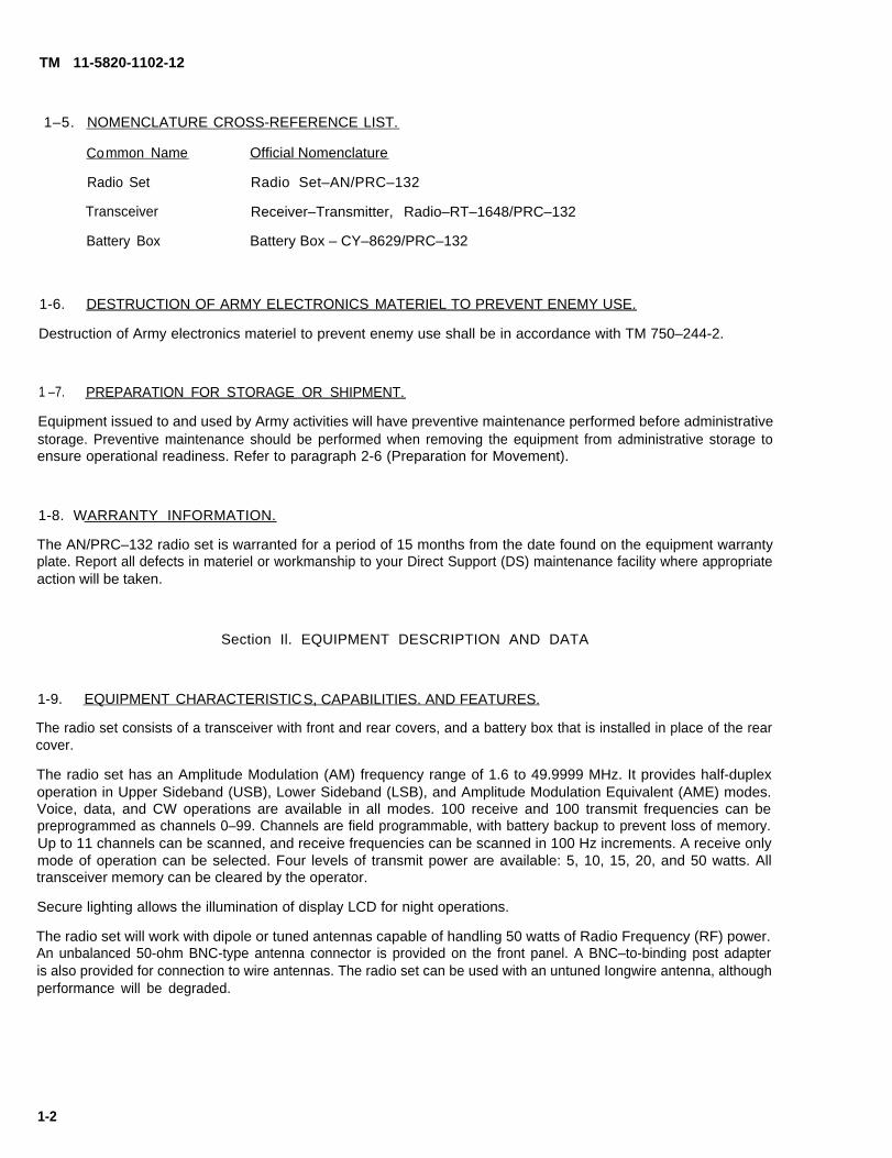
1-9. EQUIPMENT CHARACTERISTICS, CAPABILITIES. AND FEATURES.
The radio set consists of a transceiver with front and rear covers, and a battery box that is installed in place of the rearcover.
The radio set has an Amplitude Modulation (AM) frequency range of 1.6 to 49.9999 MHz. It provides half-duplexoperation in Upper Sideband (USB), Lower Sideband (LSB), and Amplitude Modulation Equivalent (AME) modes.Voice, data, and CW operations are available in all modes. 100 receive and 100 transmit frequencies can bepreprogrammed as channels 0–99. Channels are field programmable, with battery backup to prevent loss of memory.Up to 11 channels can be scanned, and receive frequencies can be scanned in 100 Hz increments. A receive onlymode of operation can be selected. Four levels of transmit power are available: 5, 10, 15, 20, and 50 watts. Alltransceiver memory can be cleared by the operator.
Secure lighting allows the illumination of display LCD for night operations.
The radio set will work with dipole or tuned antennas capable of handling 50 watts of Radio Frequency (RF) power.An unbalanced 50-ohm BNC-type antenna connector is provided on the front panel. A BNC–to-binding post adapteris also provided for connection to wire antennas. The radio set can be used with an untuned Iongwire antenna, althoughperformance will be degraded.
1-2
TM 11-5820-1102-12
The radio set can interface with a variety of auxiliary equipment necessary for mission performance.
1-10 LOCATION AND DESCRIPTION OF MAJOR COMPONENTS.
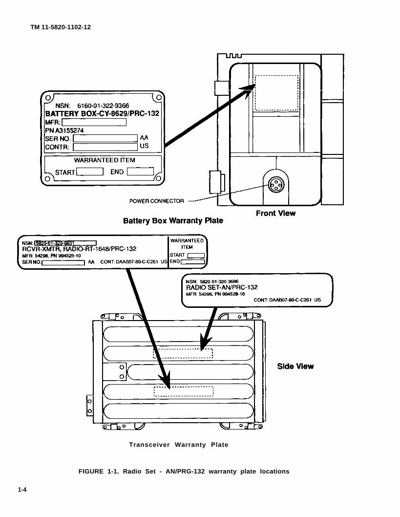
Refer to Figure 1-1 for location and contents of warranty plates or stencils.
1-10.1 External Components Refer to Figure 1-2. The AN/PRC-132 radio set consists of a transceiver (1) withfront and rear covers (2 & 3), and a battery box (4). The transceiver front panel contains operating controls,indicators, and connectors described in Chapter 2.
When in operational mode, the battery box is installed in place of the rear cover.
A battery charging connector (5) is provided on the battery box.
1-10.2 Internal Components Refer to the AN/PRC-132 Radio Set Direct Support Maintenance manual(TM 11-5820-1102-30) for a description of internal components.
1-10.3 Auxilia ry Equipment Auxiliary equipment is interfaced to the transceiver through adapter/interfacecabling.
Interface cabling is attached at either the AUDIO 1 or AUDIO 2 connector(s) on the transceiver front panel.Interface cabling is provided with the applicable auxiliary equipment.
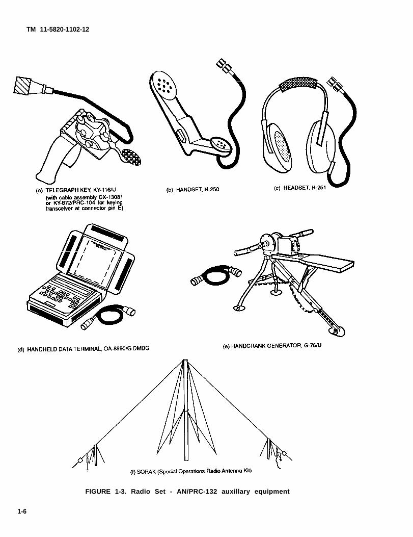
Refer to Figure 1-3. The radio set is capable of interfacing with the following auxiliary equipment items:
a. Telegraph key KY-116/U. The telegraph key (with cable assembly CX-13031 or KY-872/PRC-104 for keyingtransceiver at connector pin E) is used to send CW messages.
b. Handset H-250. The handset is used to send and receive voice messages.
c. Headset H-251. The headset is used to receive voice messages.
d. Handheld Data Terminal OA-8990/G DMDG. The data terminal is used to send and receive messages. Italso:
Stores informationPermits burst communicationMinimizes transmission timeReduces the risk of being located by radio direction-findingAssures messages are authentic
e. Hand crank generator G-76/U. The hand crank generator can be used to charge batteries and fortransceiver receive operations. The hand crank generator interconnects to the battery box charging connector.
f. SORAK (Special Operations Radio Antenna Kit). The SORAK contains a variety of antennas for use with theAN/PRC-132. SORAK antennas are connected to the transceiver front panel at the ANT BNC-type connector.Longwire antennas are connected to the ANT BNC-to-binding post adapter (which is connected to the ANTconnector) and to the GND binding post for grounding or counterpoise. Refer to Figure 1-4.
1-3
TM 11-5820-1102-12
Transceiver Warranty Plate
FIGURE 1-1. Radio Set - AN/PRG-132 warranty plate locations
1-4
TM 11-5820-1102-12
FIGURE 1-2. Radio Set - AN/PRW 32 external components
1-5
TM 11-5820-1102-12
FIGURE 1-3. Radio Set - AN/PRC-132 auxillary equipment
1-6
TM 11-5820-1102-12
1-10.4 Accessories AN/PRC-132 accessories include the transceiver front and rear covers for use in thetransport configuration.
1-11 EQUIPMENT DATA.
1-11.1 Performance Specifications
Frequency range:
Frequency steps:
Channels:
Operating modes:
Audio input:
Duty Cycle:
Input voltage:
Battery Life (BB-590)(1 each)
Battery Life (BA-5590)(2 each)
1-11.2 Microprocessor Capability
Operation:
Number of channels(preprogrammable) stored:
Scanning:
Up-down tuning:
1-11.3 Transmitter
Power output:
Impedance:
Audio bandwidth:
Antenna mismatch:
1.6 to 49.9999 MHz.
100 Hz increments.
484,000, synthesized.
LSB, USB, AME (CW and voice in all modes).
150 ohm impedance with Voice Operated Gain Adjustable Device(VOGAD) for constant audio level.
1:20 transmit to receive. 1 minute maximum continuous transmit time.
During normal operation, the only exposed voltage exceeding 30 volts root-mean-square (rms) is the antennavoltage during transmit. This voltage is a maximum of 50 volts rms when operating into a 50 ohm antenna.All external surfaces of the radio set other than the antenna terminal are at ground potential when thetransceiver GND stud is tied to ground.
It is the operator’s responsibility to understand and apply the following safety precautions during all phases ofequipment operation, service, and repair. Failure to comply with these precautions, or with specific warningselsewhere in this manual violates safety standards of design, manufacture, and intended use.
WARNING
RF VOLTAGE WARNING
Exposed metal transceiver parts can assume an RF potential to ground when antenna istuned without grounding transceiver. To avoid potential RF bums, tie transceiver GND studto ground.
WARNING
KEEP AWAY FROM LIVE CIRCUITS
The antenna is a source of electrical and radio frequency energy. NEVER TOUCH THEANTENNA WHEN THE RADIO SET IS IN USE. An RF burn may occur as a result ofcontact with an active antenna system.
1-9
TM 11-5820-1102-12
Transmit power is limitedbatteries. When batteries
WARNING
TRANSMIT POWER LIMITATION
to a maximum of 20 watts when operating with two BA-5590are combined, transmit power may be limited dependent upon
the relative state of the battery charge.
WARNING
DO NOT OPEN TRANSCEIVER CASE
Operator personnel must not remove the transceiver case. Transceiver is not repairable atoperator and unit maintenance level.
WARNING
Operator must replace both BA-5590/U with completely new batteries at the same time. Donot mix partially used batteries with brand new batteries.
If possible, the operator should use two BA-5590 batteries manufactured by the samevendor with the same date code.
WARNING
Do not attempt to transmit when charging batteries.
WARNING
A lithium-sulfur dioxide (Li-SO2) battery used with the AN/PRC-132 contains pressurizedsulfur dioxide (S02) gas. The gas is toxic, and the battery MUST NOT be abused in anyway which may cause the battery to rupture.
DO NOT heat, short circuit, crush, puncture, mutilate, or disassemble batteries.
DO NOT USE any battery which shows signs of damage, such as bulging, swellingdisfigurement, a brown liquid in the plastic wrap, a swollen plastic wrap, etc.
DO NOT test Li-SO2 batteries for capacity.
DO NOT recharge Li-S02 batteries.
DO NOT dispose of lithium batteries with ordinary trash/refuse. Turn in batteries to yourlocal servicing Defense Reutilization and Marketing Office.
1-10
TM 11-5820-1102-12
WARNING
If the battery compartment becomes hot to the touch, if you hear a hissing sound (i.e.,battery venting), or smell irritating sulfur dioxide gas, IMMEDIATELY Turn Off the equipmentand leave the area.
1. Allow the equipment to cool at least one hour.
2. Remove and replace battery after the equipment
3. If there is a safety incident, or if you believe aSafety Office/Officer, file a Quality Deficiency Report,Safety Office, Ft. Monmouth, NJ at AV 995-3112.
has cooled to the touch.
safety hazard exits, notify your localSF Form 368, and notify the CECOM
WARNING
DO NOT use a HaIon type fire extinguisher on a lithium battery fire.
In the event of a fire, near a lithium battery (ies), rapid cooling of the lithium battery (ies) isimportant. Flood the equipment with water or use a carbon dioxide (C02) extinguisher.Control of the equiment fire, and cooling, may prevent the battery from venting andpotentially exposing lithium metal. In the event that lithium metal becomes involved in fire,the use of a graphite based Class D fire extinguisher is recommended, such as Lith-X orMet-L-X.
Section Ill. PRINCIPLES OF OPERATION
1-13 GENERAL OPERATION.
Refer to Figure 1-5.
The battery box provides power to the transceiver via a power connector that mates with an external connectorlocated at back of transceiver. Connection is made automatically when battery box is attached to transceiver.The battery box is held onto rear of transceiver with latches attached to the transceiver housing. To preservebattery life, the battery box is disconnected from the transceiver when not in use.
On the transceiver front panel, there are two connections marked AUDIO 1 and AUDIO 2 for auxiliaryinput/output devices. Operator handsets, headsets, or other applicable devices can be attached at these pointsto provide operator interface to the transceiver. Refer to paragraph 1-10.3 for a full listing of auxiliaryequipment.
Also located on the transceiver front panel is a BNC-type connector marked ANT for use in connecting dipolesand other antennas that use an interconnecting coaxial cable. Antenna signal flow both to and from thetransceiver is through this BNC-type connector. For connection to Iongwire and other antennas with openterminations, a BNC-to-binding post adapter is provided as a standard accessory. A grounded binding postmarked GND is also provided on the front panel for attachment to system ground or antenna counterpoise, ifrequired.
1-11
TM 11-5820-1102-12
1-14 INTERFACES AND CONTROL.
All controls, connectors, and indicators are located on the transceiver front panel. A connector is located onthe battery box for interconnection of battery charging equipment. Transceiver functions controlled by theoperator include: operating frequency, channel selection, mode, volume, and transmit power output.
Power is applied to the transceiver by setting the POWER switch to the RX position for receive only operation,or to the 5, 10, 20, or 50 positions for transmit/receive operations.
Frequency control capabilities include: half duplex operation with separate receive and transmit frequencies,channel programming with memory for up to 100 separate receive and transmit frequencies, channel scanning,and receiver frequency scanning.
Frequency control and display functions are accomplished using the rotary select switch and three push-button switches (ENTER, FREQ SEL, and CHAN). A Liquid Crystal Display (LCD) displays frequency andchannel information. In addition, the LCD will display a when transceiver is transmitting or when a transmitfrequency is displayed.
Mode is controlled by the MODE switch.
Transmit power output is controlled by the POWER switch.
Volume is controlled by the VOLUME control. Volume increases with clockwise rotation.
The front panel includes connectors for auxiliary equipment interface and antenna connection. Two audioconnectors are provided for audio and keying accessories.
Refer to Table 2-1 for a full description of front panel controls, indicators, and connectors.
Secure lighting is provided for the LCD and is operator controlled. Secure lighting is not used during daylighthours since the LCD is easily read in normal lighting.
1-12
TM 11-5820-1102-12
FIGURE 1-5. Radio Set - AN/PRC-132 functional block diagram
1-13
TM 11-5820-1102-12
1-15 OPERATION IN RECEIVE.
During receive operations, incoming RF signals are picked up by the antenna and channeled to the transceiver.The transceiver processes the signals and sends them to the AUDIO 1 or AUDIO 2 connector and to whateverauxiliary equipment the operator happens to be using.
1-16 OPERATION IN TRANSMIT.
During transmit operations, operator information is channeled into the transceiver from the AUDIO 1 or AUDIO2 connectors. The transceiver processes the message traffic and passes outgoing RF signals to the antennafor transmission.
1-14
2-1
TM 11-5820-1102-12
CHAPTER 2
OPERATING INSTRUCTIONS
Section l. DESCRIPTION AND USE OF OPERATOR'S CONTROLS AND lNDlCATORS
2-1 CONTROLS. INDICATORS, AND CONNECTORS.
Figure 2-1 shows the location of each transceiver control, indicator, and connector. Table 2-1 lists their function.
Front panel control knobs are secured to flatted control shafts by set screws.
Mechanical stops are provided on all controls.
For VOLUME and POWER controls, clockwise rotation increases output levels.
2-1
TM 11-5820-1102-12
FIGURE 2-1. Controls, indicators and connectors
2-2
TM 11-5820-1102-12
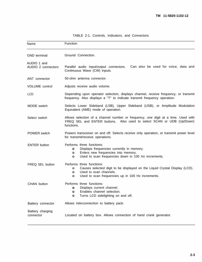
TABLE 2-1. Controls, Indicators, and Connectors
Name Function
GND terminal
AUDIO 1 andAUDIO 2 connectors
ANT connector
VOLUME control
LCD
MODE switch
Select switch
POWER switch
ENTER button
FREQ SEL button
CHAN button
Battery connector
Battery chargingconnector
Ground Connection.
Parallel audio input/output connectors. Can also be used for voice, data andContinuous Wave (CW) inputs.
50-ohm antenna connector.
Adjusts receive audio volume.
Depending upon operator selection, displays channel, receive frequency, or transmitfrequency. Also displays a "T" to indicate transmit frequency operation.
Selects Lower Sideband (LSB), Upper Sideband (USB), or Amplitude ModulationEquivalent (AME) mode of operation.
Allows selection of a channel number or frequency, one digit at a time. Used withFREQ SEL and ENTER buttons. Also used to select SCAN or UDB (Up/Down)functions.
Powers transceiver on and off. Selects receive only operation, or transmit power levelfor transmit/receive operations.
Performs
Performs
Performs
three functions:Displays frequencies currently in memory.Enters new frequencies into memory.Used to scan frequencies down in 100 Hz increments.
three functions:Causes selected digit to be displayed on the Liquid Crystal Display (LCD).Used to scan channels.Used to scan frequencies up in 100 Hz increments.
three functions:Displays current channel.Enables channel selection.Turns LCD sidelighting on and off.
Allows interconnection to battery pack.
Located on battery box. Allows connection of hand crank generator.
2-3
TM 11-5820-1102-12
Section II. OPERATOR PREVENTIVE MAINTENANCE CHECKS AND SERVICES (PMCS)
There are no operator preventive maintenance checks or services for the AN/PRC-132 radio set.
Section Ill. OPERATION UNDER USUAL CONDITIONS
2-2 ASSEMBLY AND PREPARATION FOR USE.
The AN/PRC-132 radio set requires a power source (battery box), an antenna, and either a voice, CW, or datainput/output device. Refer to paragraph 2-5 for information on your particular auxiliary equipment.
In general, use the following guidelines to prepare the radio set for use:
Inspect all equipment and accessories for damage and cleanliness.
Inspect connector pins for straightness and cleanliness.
Inspect all screws for tightness.
Verify that front and rear cover o-rings are in place and lubricated with silicone or an equivalentlubricant. Verify that battery box charging connector cap gasket is in place and lubricated.
Ensure that battery box to be used and spare batteries are fully charged.
Connect battery box to transceiver. Power connection is made automatically when battery box isattached.
Connect antenna to transceiver.
Connect auxiliary equipment to transceiver per mission requirements.
Perform initial adjustments.
2-3 INITIAL ADJUSTMENTS.
Initial transceiver adjustments consist of the following steps:
Check secure lighting.
Set receive and transmit frequencies for each channel to be used.
(Clear channels as necessary.)
2-3.1 Secure Lighting The CHAN button is used to turn LCD secure lighting on or off. Press CHAN buttontwice to turn lighting on. Press CHAN button twice to turn lighting off. Be sure to turn secure lighting off whenit is not needed to prolong battery life.
2-4
TM 11-5820-1102-12
2-3.2 Setting Channels Perform the folIowing sequence for each channel to be set.
a. Set POWER switch to RX position.
(1) Press CHAN to display current channel in the following format: HL XX (XX = two digit channelnumber). If channel is correct, press enter.
(2) Perform the following to program a new channel.
NOTE
Leading zeros must be entered. Trailing zeros must be entered for channel. Leading zerosare displayed for channel.
(a) Turn select switch to the first digit of the desired channel number. Examples: To set channel 10,turn switch to 1. To set channel 09, turn switch to 0.
CAUTION
If the LCD shows a single letter "H" or series of the letter "H" when you press the FREQ SELbutton, the transceiver is in the memory clear sequence. Press CHAN or turn thetransceiver off to abort the clear operation. Then restart the procedure you wereperforming.
(b) Press FREQ SEL to display digit selected.
(c) Turn select switch to the second digit of the channel number. Examples: To set channel 10, turnswitch to 0. To set channel 09, turn switch to 9.
(d) Press FREQ SEL to display selected channel.
(e) If the channel displayed is not correct, go back to step a(2)(a).
(9 Press ENTER to display current receive frequency for selected channel.
b. Program receive frequency as follows:
NOTE
Leading zeros must be entered. Trailing zeros need not be entered for frequency. Leadingzeros are not displayed for frequency.
(1) If frequency shown on LCD is the desired receive frequency, press ENTER. Go to step c.
(2) If frequency shown is not the desired receive frequency, proceed as follows:
2-5
TM 11-5820-1102-12
(a)
(b)
(c)
(d)
Turn select switch to the first digit of the receive frequency.to 2. To set 9.9999 MHz, turn switch to O. In this second09.9999 MHz.
CAUTION
Examples: To set 20 MHz, turn switchexample, you are really setting
If the LCD shows a single letter "H" or series of the letter ‘H” when you press the FREQ SELbutton, the transceiver is in the memory clear sequence. Press CHAN or turn thetransceiver off to abort the clear operation. Then restart the procedure you wereperforming.
Press FREQ SEL to display digit selected. If display is incorrect, press CHAN, then ENTER, and goback to step b(2)(a).
Turn select switch to the next digit of the receive frequency and press the FREQ SEL button. LCDwill show digit selected. Repeat this step until the required digits have been entered. If any entriesare incorrect, press CHAN, then ENTER, and go back to step b(2)(a).
When you have entered the required digits, press ENTER to store receive frequency in memory.
NOTE
At this point, LCD shows a small "T" above the decimal pointThis indicates that frequency shown is the transmit frequency
c. Program transmit frequency as follows:
of the frequency display.
(1) If frequency shown on LCD is the desired transmit frequency, press ENTER.
(2) If frequency shown is not the desired transmit frequency, enter a new transmit frequency in the samemanner as you would a new receive frequency. When you have entered transmit frequency, pressENTER. Transmit frequency is now stored in memory.
2-3.3 Checking a Channel To check the receive and transmit frequencies programmed for a channel, proceedas follows.
a. With transceiver in any operating position, select a channel as follows:
(1) Press CHAN to display current channel in the following format: "HL XX" (XX = two-digit channelnumber). If channel is correct, press ENTER.
(2) If you want to check a channel other than the current channel:
(a) Turn the select switch to the first digit of the desired channel number. Examples: To set channel10, turn switch to 1. To set channel 09, turn switch to 0.
2-6
TM 11-5820-1102-12
CAUTION
b.
c.
d.
2-3.4
If the LCD shows a single letter "H" or series of the letter "H" when you press the FREQ SELbutton, the transceiver is in the memory clear sequence. Press CHAN or turn thetransceiver off to abort the clear operation. Then restart the procedure you wereperforming.
(b) Press FREQ SEL to display digit selected.
(c) Turn the select switch to the second digit of the channel number. Examples: To set channel 10,turn switch to 0. To set channel 09, turn switch to 9.
(d) Press FREQ SEL to display selected channel.
(e) If channel displayed is not correct, go back to step a(2)(a).
Press ENTER to display the receive frequency for the selected channel.
Press ENTER again to display the transmit frequency for the selected channel.
Press ENTER to return to the receive frequency display.
Clearing All Channels To clear all channels to the default of 10.0000 MHz set in memory, proceed asfollows.
a. Turn POWER switch to OFF, then to RX. This clears any functions in progress.
b. Set select switch to any number.
CAUTION
The following step clears all channels in memory. Ensure that this is your intention beforepressing FREQ SEL the sixth time. To abort the operation, press CHAN button or turnPOWER switch OFF.
c. Press FREQ SEL six times. LCD will show an "H" each time FREQ SEL is pressed. After the sixth timeFREQ SEL is pressed, all frequencies of all channels are reset to 10 MHz.
2-3.5 Clearing a Single Channel Single channels are cleared by setting them to the default frequency of10.0000 MHz.
2-4 OPERATING PROCEDURE.
During setup, the operator must:
o Select power settingo Select modeo Select channelo Adjust volume
2-7
TM 11-5820-1102-12
CAUTION
If LCD shows a single letter "H" or series of the letter "H" when you press the FREQ SELbutton, the transceiver is in the memory clear sequence. Press CHAN or turn thetransceiver off to abort the clear operation. Then restart the procedure you wereperforming.
Radio operations consist of the following procedures:
o Powering upo Selecting operating modeo Selecting a channelo Scanning frequencieso Scanning channelso Going to standbyo Shutdown
24.1 Powering Up For receive only operation, set POWER switch to RX. For transmit/receive operations andcorresponding transmit power in watts, set POWER switch to 5, 10, 20, or 50.
2-4.2 Selecting Operating Mode Set MODE
o LSB - for lower sideband operation.
o USB - for upper sideband operation.
switch to:
o AME - for amplitude modulation equivalent operation.
Any setting may be used for voice, data, or CW operation.
2 4 . 3
a.
b.
Selecting a Channel Select a channel as follows.
Press CHAN to display current channel in the following format: “HL XX" (XX = two-digit channelnumber).
If a different channel is required, proceed as follows:
(1) Turn select switch to the first digit of the desired channel number. Examples: To set channel 10,turn switch to 1. To set channel 09, turn switch to 0.
CAUTION
If LCD shows a single letter ‘H’ or series of the letter "H" when you press the FREQ SELbutton, the transceiver is in the memory clear sequence. Press CHAN or turn thetransceiver off to abort the clear operation. Then restart the procedure you wereperforming.
(2) Press FREQ SEL to display digit selected.
2-8
TM 11-5820-1102-12
(3) Turn select switch to the second digit of the channel number. Examples: To set channel 10, turnswitch to 0. To set channel 09, turn switch to 9.
(4) Press FREQ SEL to display the channel selected. If channel displayed is not correct, go back to stepb(1).
c. Press ENTER to display the receive frequency.
To display the transmit frequency, press ENTER again. Transmit frequency is alsodisplayed when transmitter is keyed. A small above the decimal point indicates transmitfrequency.
24.4 Scanning Frequencies To scan receive frequencies in steps of 100 Hz, proceed as follows.
a. Set POWER switch to any operating position and select operating mode.
b. Turn select switch to UDB position.
c. Press FREQ SEL to display the current channel in the following format: "PL XX" (XX = two-digit channelnumber).
d. If a different channel is required, proceed as follows:
(1) Turn select switch to the first digit of the desired channel number. Examples: To set channel 10,turn switch to 1. To set channel 09, turn switch to 0.
If LCD shows a single letter “H" or series of the letter "H" when you press the FREQ SELbutton, the transceiver is in the memory clear sequence. Press CHAN or turn thetransceiver off to abort the clear operation. Then restart the procedure you wereperforming.
(2) Press FREQ SEL to display the digit selected.
(3) Turn select switch to the second digit of the channel number. Examples: To set channel 10, turnswitch to O. To set channel 09, turn switch to 9.
(4) Press FREQ SEL to display channel selected. If channel displayed is not correct, go back to step d(1).
e. Press ENTER to display the receive frequency,
f. At this point, frequency scan operation is enabled. To increase frequency, press FREQ SEL. Todecrease frequency, press ENTER.
g. To exit frequency scan, turn select switch to any number and press CHAN.
2-9
TM 11-5820-1102-12
2-4.5 Scanning Channels To scan through 11 channels, proceed as follows.
a Set POWER switch to any operating position and select operating mode.
b. Press CHAN to display current channel in the following format: “HL XX" (XX = two-digit channel number).
c. If a
(1)
(2)
(3)
(4)
NOTE
Receive frequency, not channel number, is displayed during scan.
different starting channel is required, proceed as follows:
Turn select switch to the first digit of the desired channel number. Examples: To set channel 10, turnswitch to 1. To set channel 09, turn switch to 0.
CAUTION
If LCD shows a single letter "H” or series of the letter "H” when you press the FREQ SELbutton, the transceiver is in the memory clear sequence. Press CHAN or turn thetransceiver off to abort the clear operation. Then restart the procedure you wereperforming.
Press FREQ SEL to display the digit selected.
Turn select switch to the second digit of the channel number. Examples: To set channel 10, turnswitch to 0. To set channel 09, turn switch to 9.
Press FREQ SEL to display both digits selected. If the channel displayed is not correct, go back tostep c(1).
d. Press ENTER. The receive frequency will be displayed.
e. Turn select switch to SCAN.
f. At this point, channel scan is enabled. Press FREQ SEL to increase the channel.
NOTE
Channel scan cycles through 11 channels. Each time FREQ SEL is pressed, one is addedto the current channel until the eleventh channel is reached. After the eleventh channel,the scan returns to the first channel. For example, if the starting channel is 10, scan willbe as follows: 10, 11, 12, 13, 14, 15, 16, 17, 18, 19, 20, 10, 11, etc.
Scanning stops at channel 99 even if fewer than eleven channels have been scanned. Forexample, if the starting channel is 95, scan will be as follows: 95, 96, 97, 98, 99, 95, 96, etc.
g. To exit channel scan, turn select switch to any number and press CHAN.
2-10
TM 11-5820-1102-12
2-4.6 Going To Standby There is no standby operation for the AN/PRC-132. Turn POWER OFF when radioset is not in use.
2-4.7 Shutdown To shut down the AN/PRC-132, turn POWER switch to the OFF position. The radio set cannow be disassembled for movement or left as is for use at a later time.
NOTE
Shutdown does not clear channels and frequencies programmed in memory.
2-5 OPERATION OF AUXILIARY EQUIPMENT.
For auxiliary equipment operations, refer to the applicable manual(s) for equipment to be used with the radioset.
2-6 PREPARATION FOR MOVEMENT.
Typically, the battery box is removed from the transceiver and front and rear panels are attached to thetransceiver for transport and storage.
To prepare radio set for movement, first shut down transceiver. Remove antenna and other attached auxiliaryequipment. Latch transceiver front cover in place. Remove battery box. Latch rear cover in place.
Front and rear panel covers attach to the transceiver and provide protection for the transport conceguration.Figure 2-2 illustrates the transport conciguration. Normally, the transceiver is carried in the standard SOFrucksack.
Before subjecting the radio set to extreme environmental conditions such as caching or immersion, ensure thatfront and rear cover o-rings are in place and lubricated, and install front and rear covers.
Section IV. OPERATION UNDER UNUSUAL CONDITIONS
The AN/PRC-132 radio set is designed to operate in all types of weather and terrain, and to withstand exposureto severe environmental extremes. The radio set can withstand shock and vibration.
2-7 OPERATION IN UNUSUAL WEATHER.
There are no special procedures for operations in unusual weather.
The AN/PRC-132 radio set can withstand the following conditions for limited periods of time:
HUMIDITY: The radio set can withstand (with seals opened) exposure to constant high humidity conditionssuch as those found in tropical areas, and cyclical high humidity conditions such as those found in opentropical areas where solar radiation is a factor. The radio set will resist fungus growth.
TEMPERATURE: The radio set will operate over a temperature range of 30 to +65 degrees C (-22 to +149degrees F), and can withstand storage over a temperature range of -40 to +85 degrees C (40 to +185degrees F). The LCD may respond sluggishly in extremely cold temperatures. Most LCDS exhibit sluggish
2-11
TM 11-5820-1102-12
response times at lower temperatures, some taking up to .5 second to respond to a change at -30 degreesC (-22 degrees F). If this does occur, it is a normal response.
SALT AIR: The radio set can resist the effects of exposure to marine atmosphere.
DUST and SAND: The radio set can withstand the effects of blowing dust and sand. The LCD window ismade of a high strength polycarbonate. Skirted knobs or boots are used on front panel controls to protectseals and moving parts. All mating surfaces are sealed to prevent sand or dust from penetrating into theequipment.
ALTITUDE: The radio set will operate at ground elevation sites up to 15,000 feet (4572 meters), and can bestored at elevations up to 30,000 feet (9144 meters), The radio set can be air-transported in non-pressurizedcabins. In addition, the radio set was designed to survive rapid decompression without damage or degradationin performance.
2-8. FORDING AND SWIMMING.
When fording or swimming, configure the transceiver for transport.
The transceiver can be immersed to depths up to 3 feet. Note that front and rear covers must be on for anyimmersion of the transceiver.
Sealing of the transceiver in the transport configuration is accomplished with front and rear panel covers. Eachcover contains a groove for an o-ring. The o-ring mates with the edges of the front and rear of the transceiverhousing. Latches are provided on the housing to pull the covers tight and form a high pressure seal.
The battery box is waterproof to depths up to 3 feet.
2-9. JAMMING AND ECM PROCEDURES.
Follow current military guidelines for operation in an environment where jamming and ECM may be present.
2-12
2-13
TM 11-5820-1102-12
FIGURE 2-2. Transceiver transport configuration
3-1
TM 11-5820-1102-12
CHAPTER 3
OPERATOR MAINTENANCE
Section I. LUBRICATION INSTRUCTIONS
Lubrication is performed at the unit maintenance level.
Section Il. TROUBLESHOOTING PROCEDURES
Refer to paragraph 4-11 for troubleshooting procedures.
Section Ill. MAINTENANCE PROCEDURES
There are no operator maintenance procedures for the AN/PRC-132 radio set.
3-1
4-1
TM 11-5820-1102-12
CHAPTER 4
UNIT MAINTENANCE
Section I. REPAIR PARTS AND SPECIAL TOOLS
4-1 COMMON TOOLS AND EQUIPMENT.
For authorized common tools and equipment refer to the Modified Table of OrganizationalEquipment (MTOE) applicable to your unit.
4-2 SPECIAL TOOLS. TMDE. AND SUPPORT EQUIPMENT.
Refer to the Repair Parts and Special Tools List (TM 11-5820-1102-23P) and to the Maintenance Allocation Chart(Appendix B) for information concerning special tool requirements, TMDE, and support equipment requirementsfor unit maintenance actions.
No special tools or equipment are required.
4-3 REPAIR PARTS.
Repair parts are listed and illustrated in the Repair Parts and Special Tools List (TM 11-5820-1102-23P).
4-4
a.
b.
4-5
Section Il. SERVICE UPON RECEIPT
CHECKING U NPACKED EQUIPMENT.
Inspect the equipment for damage incurred during shipment. If the equipment has been damaged, reportthe damage to the Property Accounting Officer.
Check the equipment against the packing slip to see if the shipment is complete. Report alldiscrepancies to the Property Accounting Officer.
INSTALLATION.
4-5.1 Tools and Materiels Required for Installation No tools, test equipment, or special materiels are requiredfor installation.
4-5.2 Assembly of Equipment The AN/PRC-132 radio set is shipped fully assembled. The only initial actionnecessary before installing the radio set in its operational configuration is to put batteries in the battery box.
4-1
TM 11-5820-1102-12
The battery box includes a rear cover and a housing with mating connectors for 99-590 or BA-5590 batteries.Performance is obtained with the following configurations:
A single BB-590 battery (50 watts transmit power).Two 99-590 batteries (50 watts transmit power).Two BA-5590 batteries (20 watts transmit power).A combination of one 99-590 and one BA-5590 battery may also be used.
TRANSMIT POWER LIMITATION
Transmit power is limited to a maximum of 20 watts when operating with two BA-5590batteries. When batteries are combined, transmit power may be limited dependent uponthe relative state of the battery charge.
When used in combination, the BA-5590 will tend to keep the BB-590 charged, whether the radio is in operationor not. Only the 99-590 nickel cadmium battery is rechargeable.
Transmit operation with 89-590 and BA-5590 batteries used in combination may result in reduced transmitpower output.
4-6 PRELIMINARY SERVICING AND ADJUSTMENT OF EQUIPMENT.
Preliminary actions include:
Verify that battery box will accept batteries.
Verify that battery box will attach to transceiver.
Verify that transceiver will power on.
For transport configuration, verify that front and rear cover o-rings are in place and lubricated withsilicon or an equivalent lubricant. Verify that transceiver front and rear covers fit and latch properly.
Verify that all external connectors and connector pins are in good condition and that no pins are bentor broken.
Verify that all switches and controls are present and function properly.
4-7 CIRCUIT ALINEMENT.
Circuit alinement is not required.
4-2
TM 11-5820-1102-12
Section Ill. UNIT PREVENTIVE MAINTENANCE CHECKS AND SERVICES (PMCS)
4-8 GENERAL.
PMCS are essential to the efficient operation of the system and to prevent possible damage that might occurthrough neglect or failure to observe warning symptoms in a timely manner. PMCS perfomed by unitmaintenance personnel are limited to those functions accomplished from outside the equipment housing.
4-8.1 Maintenance Forms and Records The forms and records have several uses including:
(1) a permanent record of the services, repairs and modifications made on the equipment.
(2) reports to the next level of maintenance and the commander.
(3) a checklist of the equipment status after its last use, and whether any faults have been fixed.
For more information on forms and records, see DA PAM 738-750.
4-8.2 Routine Checks Routine checks such as cleaning, dusting, washing, stowing items not in use, coveringunused receptacles, and checking for damage are not covered in the PMCS checks. They are things whichshould be done any time they are noticed.
4-8.3 PMCS Unit maintenance PMCS arethe equipment in good operating condition
Ensure all discrepancies are noted and corrected.
the required periodic inspections and actions necessary to keep
4-8.4 System Readiness Criteria System Readiness Criteria are those standard, specified requirements thesystem must meet to be mission-capable.
4-9 PMCS TABLE.
PMCS Table 4-1 lists all the scheduled maintenance tasks required for the radio set. The columns of the tableare as follows:
a. Item No. This column contains a number for each procedure to be performed. when reporting malfunctionsor failures on DA Form 2404, Equipment Inspection and Maintenance Worksheet, enter this number in the TMItem No. column.
b. Interval. These columns tell when to do a procedure. A letter in a column tells which procedures apply.Some procedures will have more than one letter.
c. Item To Be lnspected/Procedure. This column has the name of the item to be inspected and tells how todo the required checks and services on it. Carefully perform these instructions in the order listed.
d. Equipment Is Not Ready/Available If:. This column tells the conditions which will cause the equipment notto be ready (RED) for readiness reporting.
4-3
TM 11-5820-1102-12
4-10 PMCS PROCEDURES.
NOTE
Within designated intervals, these checks are to be performed in the order listed. If theequipment must be kept in continuous operation, check and service only those items thatcan be checked and serviced without disturbing operation. Make the complete checks andservices when the equipment can be shut down.
4-10.1 Before You Operate Always keep in mind and observe the WARNINGS and CAUTIONS containedthis technical manual (TM) and plates installed on the equipment. Perform the before (B) PMCS fromTable 4-1.
4-10.2 While You Operate Always keep in mind and observe the WARNINGS and CAUTIONS containedthis technical manual (TM)Table 4-1.
4-10.3
4-10.4
4-10.5
4-10.6
4-10.7
4-10.8
After You Operate
and plates installed on the equipment. Perform the during (D) PMCS from
Perform the after (A) PMCS from Table 4-1.
in
in
Weekly
Monthly
Perform the Weekly (W) PMCS from Table 4-1.
Perform the monthly (M) PMCS from Table 4-1.
If Somethinq Doesn’t Work Troubleshoot with the instructions in this manual and notify the supervisor.
Order Always do the preventive maintenance in the same order.
Reporting If anythingapplicable form. If something is
goes wrong that cannot be fixed, write it on the DA Form 2404, or otherseriously wrong, report it to the next highest maintenance level IMMEDIATELY.
WARNING
RF VOLTAGE WARNING
Exposed metal transceiver parts can assume an RF potential to ground when antenna istuned without grounding transceiver. To avoid potential RF burns, tieto ground.
transceiver GND stud
WARNING
KEEP AWAY FROM LIVE CIRCUITS
The antenna is a source of electrical and radio frequency energy.ANTENNA WHEN THE RADIO SET IS IN USE. An RF burn maycontact with an active antenna system.
NEVER TOUCH THEoccur as a result of
4-4
TM 11-5820-1102-12
WARNING
DO NOT OPEN TRANSCEIVER CASE
Operator and unit maintenance personnel must not remove the transceiver case.Transceiver is not repairable at operator and unit maintenance level.
WARNING
Operator must replace both BA-5990/U with completely new batteries at the same time. Donot mix partially used batteries with brand new batteries.
If possible, the operator should use two BA-5590 batteries manufactured by the samevendor with the same date code.
WARNING
Do not attempt to transmit when charging batteries.
WARNING
A lithium-sulfur dioxide (LiSO2) battery used with the AN/PRC-132 contains pressurizedsulfur dioxide (SO2) gas. The gas is toxic, and the battery MUST NOT be abused in anyway which may cause the battery to rupture.
DO NOT heat, short circuit, crush, puncture, mutilate, or disassemble batteries.
DO NOT USE any battery which shows signs of damage, such as bulging,disfigurement, a brown liquid in the plastic wrap, a swollen plastic wrap, etc.
DO NOT test Li-S02 batteries for capacity.
DO NOT recharge Li-S02 batteries.
swelling,
DO NOT dispose of lithium batteries with ordinary trash/refuse. Turn in batteries to yourlocal servicing Defense Reutilization and Marketing Office.
4-5
TM 11-5820-1102-12
If the battery compartment becomes hot to the touch, if you hear a hissing sound (i.e.,battery venting), or smell irritating sulfur dioxide gas, IMMEDIATELY Turn Off the equipmentand leave the area.
1.
2.
3.
Allow the equipment to cool
Remove and replace battery
If there is a safety incident,
at least one hour.
after the equipment has cooled to the touch.
or if you believe a safety hazard exists, notify your localSafety Office/Officer, file a Quality Deficiency Report,Safety Office, Ft. Monmouth, NJ at AV 995312.
SF Form 368, and notify the CECOM
DO NOT use a Halon type fire extinguisher on a lithium battery fire.
In the event of a fire, near a lithium battery(ies), rapid cooling of the lithium battery(ies) isimportant. Flood the equipment with water or use a carbon dioxide (CO2) extinguisher.Control of the equipment fire, and cooling, may prevent the battery from venting andpotentially exposing lithium metal. In the event that lithium metal becomes involved in fire,the use of a graphite based Class D fire extinguisher is recommended, such as Lith-X orMet-L-X.
DO NOT store batteries in unused equipment for more than 30 days.
DO NOT store lithium batteries with other hazardous materials and keep them away fromopen flame or heat.
4-6
TM 11-5820-1102-12
TABLE 4-1. Unit Preventive Maintenance Checks and Services
NOTE
For interval; B = before, D = during, A = after, W = weekly, and M = monthly.
Item Interval Item to be Inspected Equipment is notNo. BDAWM Procedure Ready/Available if:
1 B A
2 B A
3
4
5
6
7 B
B A
B A
B A
8 A
9 B D A
10 B D A
11 B D A
Check for cleanliness.
Check all knobs and controlsfor damage and correct freedomof movement. All hardware shouldbe checked for tightness.
Check front panel lens to be sureit has not been cracked.
Check all connectors for damagedpins.
Check for broken latches or latchhooks.
M Check for o-ring and its lubrication.
Be sure that transceiver and batterybox mate properly.
Be sure that transceiver front andrear covers mate properly.
Check screws for tightness.
Check battery box vent to be sureit is not clogged with mud or dirt.
Check hexseal on ENTER,FREQ SEL and CHAN buttons fortears, cracks, or holes. Forwardtransceiver to Direct SupportMaintenance facility for repairif damaged.
Knobs missing or broken,or incorrect freedom ofmovement.
Lens cracked.
Bent or missing pins.
Transceiver and batterybox do not mate.
Unable to clean vent.
Boots torn.
NOTE
Spot paint as necessary.
4-7
TM 11-5820-1102-12
Section IV. TROUBLESHOOTING
Troubleshooting procedures are the same for both the operator and unit maintenance.
The component most likely to cause a given failure is listed first and should be substituted first. If thereplacement does not correct the failure, leave it attached to the transceiver and substitute the next componenton the list. Continue substitution, in the order listed in Table 4-2, until failure is corrected.
When a substitution corrects a failure, assume the component replaced is defective and set it aside for repair,leaving the substituted component in the system. Replace previously substituted components one at a time,in reverse order of removal.
After each replacement, recheck the radio set to ensure that the original failure has not returned.
After completion of this procedure, perform general operational tests before returning the radio set to service.Forward defective component(s) to the Direct Support Maintenance facility for repair.
4-11
If the
TROUBLESHOOTING PROCEDURE.
AN/PRC-132 radio set fails any of the following tests, refer to Table 4-2 for replacement sequence.
TABLE 4-2 Symptom Index
Failed Test Replacement Sequence TroubleshootingProcedure (para.)
Unable to poweron transceiver.
Unable to poweron transceiver.
Unable to poweron transceiver.
Unable to programfrequencies.
Unable to scan.
Unable tocommunicate withknown good radio set.
Unable tocommunicate withknown good radio set.
Unable tocommunicate withknown good radio set.
Batteries 4-12.1
Battery Box 4-12.1
Transceiver 4-12.1
Transceiver 4-12.2
Transceiver 4-12.2
Transceiver 4-12.3
Auxiliary equipment 4-12.3
Antenna 4-12.3
4-8
TM 11-5820-1102-12
4-12 GENERAL OPERATIONAL TESTS.
4-12.1 Power On Test Ensure that transceiver will power on.
4-12.2 Programming Test Ensure that receive and transmit frequencies can be programmed and thatfrequency scan and channel scan work correctly.
4-12.3 Operational Test Attempt communications with a known good radio set.
Perform all communications operations (both transmit and receive) to verify that radio set under test is fullyoperational.
Section V. MAINTENANCE PROCEDURES
Refer to Appendix B, Maintenance Allocation Chart, for maintenance times and limitations.
4-13 AN/PRC-132 UNIT MAINTENANCE.
Radio set unit maintenance includes:
InspectionServiceTest
4-13.1 AN/PRC-132 Inspection After each use, perform an external visual inspection of the radio set. Referto the PMCS chart.
4-13.2 AN/PRC-132 Service. The only service required is to maintain cleanliness of the radio set, replacebatteries when necessary, lubricate o-rings, and repair when damaged.
The radio set and its accessories should be cleaned as required. Remove dust and dirt from surfaces with acloth or a soft bristle brush. Isopropyl alcohol or mild soapy water may be used as required. Rinse by wipingwith a clean cloth moistened in water. Dry using a cloth.
Remove dust and dirt from connectors with a soft, dry, bristle brush.
Lubrication applies to the transceiver front and rear cover o-rings which must be lubricated as required tomaintain watertight integrity.
Check front and rear cover o-rings for damage or dirt. Clean or replace as required. Coat o-ringswith silicon or an equivalent lubricant.
Check battery box charging connector cap gasket for proper lubrication.
4-9
TM 11-5820-1102-12
4-13.3 AN/PRC-132 Test Radio set testing is limited to a functional verification that transceiver and batterybox work together, and that all transceiver functions can be performed.
Refer to paragraphs 4-12.1 and 4-12.2 for functional testing.
4-14 CY-862WPRC-132 UNIT MAINTENANCE.
Battery box unit maintenance includes:
o Inspectiono Serviceo Testo Repair
4-14.1 CY-8629/PRC-132 Inspection After each use, perform an external visual inspection of the battery box.Refer to PMCS chart.
4-14.2 CY-8629/PRC-132 Service The only service required is to maintain battery box cleanliness, changebatteries when necessary, and repair when damaged.
The battery box should be cleaned as required. Remove dust and dirt from surfaces with a cloth or a softbristle brush. Isopropyl alcohol or mild soapy water may be used as required. Rinse by wiping with a cleancloth moistened in water. Dry using a cloth.
Use a dry bristle brush to remove mud or dirt from the vent screen.
Remove dust and dirt from connectors with a soft, dry, bristle brush.
4-14.3 CY-8629/PRC-132 Test Battery box testing is limited to a functional verification that transceiver andbattery box work together, and that all transceiver functions can be performed.
Refer to paragraph 4-12 for functional and performance testing.
4-14.4 CY-8629/PRC-132 Repair Battery box repair is limited to battery replacement.
The battery box does not have to be separated from the transceiver during battery replacement. Batteries canbe installed or replaced by disengaging latches that hold rear cover of battery box to the battery box housing.Ensure transceiver is in OFF position. Remove cover. Grasp exposed batteries and remove them from batterybox. Refer to Figure 4-1. Turn batteries so battery connectors will mate with connectors in the battery boxhousing. Install batteries. Within battery box housing, guide pins will position batteries for proper connectoralinement. Mating connectors inside housing will engage battery connectors as batteries are installed. Replacebattery box cover and latch in place.
4-14.5 CY-8629/PRC-132 Battery Charging BB-590 batter(ies) can be recharged with the handcrank generator.The generator interconnection cable is connected to the battery box battery charging connector. Fullydischarged batteries take approximately 6 hours to recharge.
4-10
TM 11-5820-1102-12
Do not attempt to transmit when charging batteries.
4-15 RT-1648/PRC-132 UNIT MAINTENANCE.
Transceiver unit maintenance includes:
InspectionRepairTest
4-15.1 RT-1648/PRC-132 Inspection After each use, perform an external visual inspection of the transceiver.Refer to PMCS chart.
4-15.2 RT-1648/PRC-132 Repair Transceiver repair is limited to the replacement of knobs.
To remove knobs: Rotate knob (or shaft if knob is missing) fully counterclockwise (CCW). Use an allen wrenchto loosen set screw. Remove knob.
To install knobs: Replace knob, being careful to aline knob marker with appropriate markings on transceiverfront panel. Use an allen wrench to tighten set screw.
4-15.3 RT-1648/PRC-132 Test Transceiver testing covers both functional and performance testing. Refer toparagraph 4-12.
Section VI. PREPARATION FOR STORAGE OR SHIPMENT
Refer to paragraph 2-6 to prepare the AN/PRC-132 radio set for storage or shipment.
NOTE
Clear radio memory before storage or shipment.
4-11
TM 11-5820-1102-12
FIGURE 4-1. Battery installation
4-12
A-1
TM 115820-1102-12
APPENDIX A - REFERENCES
A-1 . SCOPE
This appendix lists all forms, field manuals, technical manuals, and miscellaneous publications referenced in thismanual.
A-2.
A-3.
A-4.
FORMS
DA Form 2404
DA Form 2028-2
SF 361
SF 364
SF 368
TECHNICAL MANUALS
TM 11-5820-1102-23P
TM 11-5820-1102-30
TM 750-244-2
TM 11-6115-470-10
MISCELLANEOUS PUBLICATIONS
DA PAM 25-30
DA PAM 738-750
Supply Bulletin 11-628
Equipment Inspection and Maintenance Worksheet
Recommended Changes to Publications and Blank Forms
Transportation Discrepancy Report
Report of Discrepancy
Product Quality Deficiency Report
Repair Parts and Special Tools List
AN/PRC-132 Radio Set Direct Support Maintenance
Destruction of Army Electronics Materiel to Prevent Enemy Use
Generator, G-76/U
Consolidated Index of Army Publications and Blank Forms
The Army Maintenance Management System (TAMMS)
Headset, H-251
A-1
B-1
TM 11-5820-1102-12
APPENDIX B - MAINTENANCE ALLOCATION CHART (MAC)
Section I. INTRODUCTION
1-1 GENERAL
This Maintenance Allocation Chart (MAC) provides a summary of the maintenance operations for theAN/PRC-132. It authorizes categories of maintenance for specific maintenance functions on repairable items andlists the tools and equipment required to perform each function.
1-2. MAINTENANCE FUNCTIONS
Maintenance functions will be limited to and defined as follows:
a. Inspect. To determine the serviceability of an item by comparing its physical, mechanicaland/or electrical characteristics with established standards through examination.
b. Test. To verify serviceability and detect incipient failure by measuring the mechanical orelectrical characteristics of an item and comparing those characteristics with prescribedstandards.
c. Service. Operations required periodically to keep an item in proper operating condition.
d. Install. The act of emplacing, seating or fixing into position an item, part or module in a manner to allowproper function of an equipment or system.
e. Replace. The act of substituting a serviceable like type part, subassembly, or module for an unserviceablecounterpart.
f. Repair. The application of maintenance services or other maintenance actions to restore serviceability to anitem by correcting specific damage, fault, malfunction in a part, subassembly, module, end item or system.
g. Overhaul. That maintenance effort necessary to restore an item to a completely serviceable/operationalcondition.
1-3. COLUMN ENTRIES
a. Group Number. Column 1 lists group numbers, the purpose of which is to identify components, assemblies,subassemblies and modules with the next higher assembly.
b. Component/Assembly. Column 2 contains the names of components, assemblies, subassemblies andmodules for which maintenance is authorized.
c. Maintenance Function. Column 3 lists the functions to be performed on the item listed in Column 2.
B-1
TM 11-5820-1102-12
d. Maintenance Category. Column 4 specifies, by the listing of a "work time" figure in the appropriatesubcolumn(s) the lowest level of maintenance authorized to perform the maintenance function listed in column3. This figure represents the active time required to perform the maintenance function at the indicated categoryof maintenance. Subcolumns of column 4 are as follows:
C
O
F
H
D
Operator/Crew
Unit
Direct Support
General support
Depot
e. Tools and Equipment. Column 5 specifies, by code, those common tool sets and special tools, test andsupport equipment required to perform the designated function.
f. Remarks. Column 6 contains an alphabetic code which leads to the remarks in Section IV, Remarks, whichis pertinent to the item opposite the particular code.
14. TOOLS AND TEST EQUIPMENT REQUIREMENTS (SECTION Ill)
a. Tools or Test Equipment Reference Code. The numbers in this column coincide with the numbers usedin the tools and equipment column of the MAC. The numbers indicate the applicable tool or test equipmentfor the maintenance functions.
b. Maintenance Category. The codes in this column indicate the maintenance category allocated the tools ortest equipment.
c. Nomenclature. This column lists the noun name and nomenclature of the tools and test equipment requiredto perform the maintenance functions.
1-5. REMARKS
a. Reference Code. The code refers to the appropriate item in Section II, Column 6.
b. Remarks. This column provides the required explanatory information necessary to clarify items appearingin Section Il.
B-2
00
01
0101
010101
010102
010103
01010301
TM 11-5820-1102-12
SECTION II - MAINTENANCE ALLOCATION CHARTFOR RADIO SET, AN/PRC-132
CHANGE 1 B-3
010104
01010401
01010402
01010403
01010404
01010405
01010406
01010407
01010408
TM 11-5820-1102-12
SECTION II - MAINTENANCE ALLOCATION CHARTFOR RADIO SET, AN/PRC-132
B-4 CHANGE 1
01010409
01010410
01010411
01010412
0101041201
02
0201
0202
020201
TM 11-5820-1102-12
SECTION II - MAINTENANCE ALLOCATION CHARTFOR RADIO SET, AN/PRC-132
CHANGE 1 B-5
TM 11-5820-1102-12
SECTION Ill - TOOLS AND TEST EQUIPMENT REQUIREMENTSFOR RADIO SET, AN/PRC-132
B-6 CHANGE1
LOGSA
6130-01-238-8240
LOGSA
6625-01-145-2430
LOGSA
6625-01-312-8810
LOGSA
6625-01-191-7679
LOGSA
6625-01-271-3012
LOGSA
6625-01-120-3501
LOGSA
6625-01-217-0054
LOGSA
6625-01-187-7847
LOGSA
6625-01-136-3170
LOGSA
5895-01-119-1180
LOGSA
5985-00-713-4356
LOGSA
6625-01-257-5604
LOGSA
6625-01-264-5552
LOGSA
5180-00-064-5178
LOGSA
6625-01-021-0236
LOGSA
MIL-STD-RE75G15
LOGSA
RO
LOGSA
LOGSA
LOGSA
6625-01-021-0236
TM 11-5820-1102-12
SECTION IV - REMARKSFOR RADIO SET,AN/PRC-132
CHANGE 1 B-7/(B-8 BLANK)
TM 11-5820-1102-12
APPENDIX C - COMPONENTS OF END ITEM AND BASIC ISSUE ITEMS
Section 1. INTRODUCTION
C-1 . SCOPE
This appendix lists Components of End Item and Basic Issue Items (Bll) for the AN/PRC-132 to help youinventory items required for safe and efficient operation.
C-2. GENERAL
The Components of End Item and Basic Issue Lists are divided into the following sections:
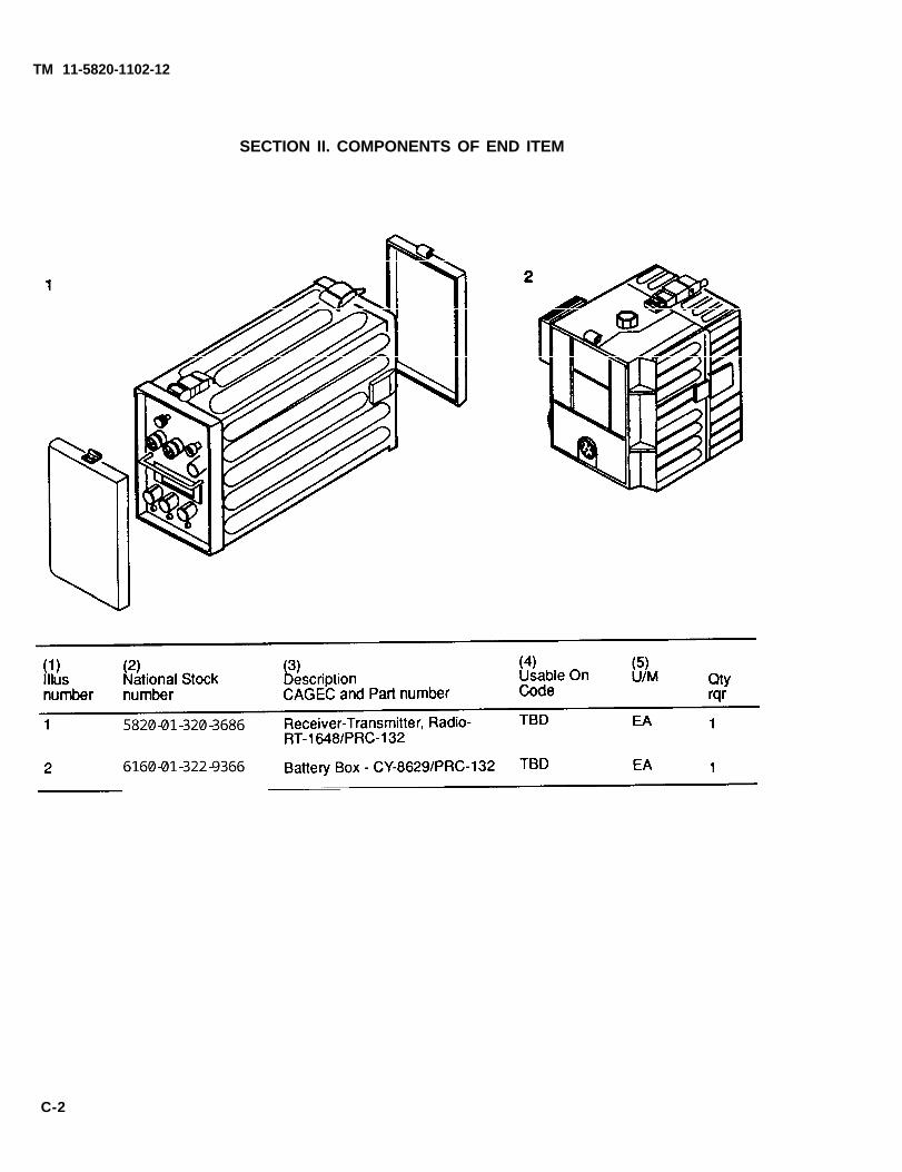
a. Section Il. Components of End Item. This listing is for informational purposes only, and is not authority torequisition replacements. These items are part of the end item, but are removed and separately packaged fortransportation or shipment. As part of the end item, these items must be with the end item whenever it is issuedor transferred between property accounts: Illustrations are furnished to assist you in identifying the items.
b. Section Ill. Basic Issue Items. These are the minimum essential items required to place the AN/PRC-132 inoperation, to operate it, and to perform emergency repairs. Although shipped separately packaged, BII must bewith the AN/PRC-132 during operation and whenever it is transferred between property accounts. Theillustrations will assist you with hard-to-identify items. This manual is your authority to request/requisitionreplacement Bll, based on TOE/MTOE authorization of the end item.
C-3. EXPLANATION OF COLUMNS
The following provides an explanation of columns found in the tabular listings:
APPENDIX C C-1COMPONENTS OFEND ITEM ANDBASIC ISSUE ITEMS
a. Column (1) - Illustration Number (Illus Number). This column indicates the number of the illustration in whichthe item is shown.
b. Column (2) - National Stock Number. Indicates the National stock number assigned to the item and will beused for requisitioning purposes.
c. Column (3) - Description. Indicates the Federal item name and, if required, a minimum description to identifyand locate the item. The last line for each item indicates the CAGEC (in parentheses) followed by the partnumber.
d. Column (4) - Unit of Measure (U/M). Indicates the measure used in performing the actualoperational/maintenance function. This measure is expressed by a two-character alphabetical abbreviation (eg.,ea, in, pr).
e. Column (5) - Quantity required (Qty rqr). Indicates the quantity of the item authorized to be used with/on theequipment.
C-1
1
2
TM 11-5820-1102-12
SECTION II. COMPONENTS OF END ITEM
C-2
LOGSA
LOGSA
LOGSA
5820-01-320-3686
LOGSA
6160-01-322-9366
TM 11-5820-1102-12
SECTION III. BASIC ISSUE ITEMS
C-3
LOGSA
5965-00-043-3460
LOGSA
5820-01-102-3921
LOGSA
5805-00-503-3395
LOGSA
5985-00-831-5991
LOGSA
6625-01-136-3170
LOGSA
5965-00-043-3463
LOGSA
6140-01-063-3918
LOGSA
6135-01-036-3495
LOGSA
LOGSA
5965-00-043-3460
TM 11-5820-1102-12
APPENDIX D - ADDITIONAL AUTHORIZATION
Section I. INTRODUCTION
D-1 . SCOPE
LIST (AAL) ITEMS
This appendix lists additional items you are authorized for the support of the AN/PRC-132.
D-2. GENERAL
This list identifies items that do not have to accompany the AN/PRC-132 and that do not have to be turned inwith it. These items are all authorized to you by CTA, MTOE, TDA, or JTA.
D-3. EXPLANATION OF LISTING
National stock numbers, descriptions, and quantities are provided to help you identify and request theadditional items you require to support this equipment. The items are listed in alphabetical sequence by itemname under the type document (ie., CTA, MTOE, TDA, or JTA) which authorizes the item(s) to you.
Section Il. ADDITIONAL AUTHORIZATION LIST
(1) (2) (3) (4)National Stock Description U/M QtyNumber CAGEC & Part Number Auth Usable on Code
MTOE AUTHORIZED ITEMS
(To Be Determined)
CTA AUTHORIZED ITEMS
(To Be Determined)
D-1
TM 11-5820-1102-12
APPENDIX E-EXPENDABLE SUPPLIES AND MATERIELS LIST
Section I. INTRODUCTION
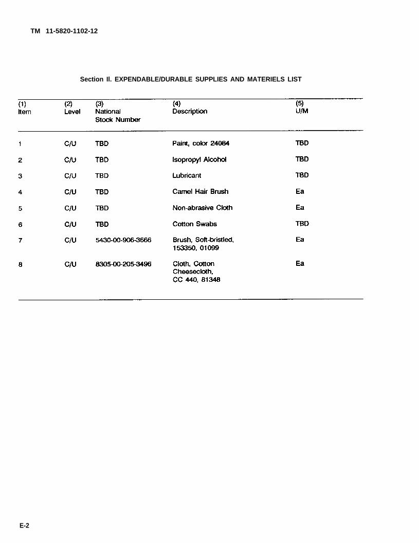
E-1. SCOPE. This appendix lists expendable supplies and materiels you will need to operate and maintainthe AN/PRC-132. This listing is for informational purposes only and is not authority to requisition the listeditems. These items are authorized to you by CTA 50-970, Expendable/Durable Items (except Medical, ClassV, Repair Parts, and Heraldic Items), or CTA 8-100, Army Medical Department Expendable/Durable Items.
E-2. EXPLANATION OF COLUMNS
a. Column (1) - Item number. This number is assigned to the entry in the listing and is referenced in thenarrative instructions to identify the materiel (eg., "Use cleaning compound, item 5, app. D").
b. Column (2) - Level. This column identifies the lowest level of maintenance that requires the listed item.
C - Operator/CrewU - Unit MaintenanceF - Direct Support MaintenanceH - General Support Maintenance
c. Column (3) - National Stock Number. This is the national stockrequest or requisition the item.
d. Column (4) - Description. Indicates the Federal item name and,item, The last line for each item indicates the Commercial andparentheses followed by the part number.
number assigned to the item; use it to
if required, a description to identify theGovernment Entity Code (CAGEC) in
e. Column (5) - Unit of Measure (U/M). Indicates the measure used in performing the actual maintenancefunction. This measure is expressed by a two-character alphabetical abbreviation (eg., ea, in, pr). If the unitof measure differs from the unit of issue, requisition the lowest unit of issue that will satisfy your requirements.
E-1
TM 11-5820-1102-12
Section Il. EXPENDABLE/DURABLE SUPPLIES AND MATERIELS LIST