41
OPERATOR’S MANUAL Model 150, 152, 162, & 168 Soft Serve Freezers Original Operating Instructions 028749- M 8/13/08 (Original Publication) Updated 8/3/15
OPERATOR’SMANUAL
Model 150, 152, 162, & 168Soft Serve Freezers
Original Operating Instructions
028749-M8/13/08 (Original Publication)Updated 8/3/15

Complete this page for quick reference when service is required:
Taylor Distributor:
Address:
Phone:
Service:
Parts:
Date of Installation:
Information found on data plate:
Model Number:
Serial Number:
Electrical Specs: Voltage Cycle
Phase
Maximum Fuse Size: Amps
Minimum Wire Ampacity: Amps
Part Number:
E 2008 Carrier Commercial Refrigeration, Inc.028749-MAny unauthorized reproduction, disclosure, or distribution of copies by any person of any portion of this work may bea violation of Copyright Law of the United States of America and other countries, could result in the awarding of StatutoryDamages of up to $250,000 (17 USC 504) for infringement, and may result in further civil and criminal penalties.All rights reserved.
Taylor Companya division of Carrier Commercial Refrigeration, Inc.750 N. Blackhawk Blvd.Rockton, IL 61072

Table of Contents Models 150, 152, 162, 168
Table of Contents
Section 1 To the Installer 1. . . . . . . . . . . . . . . . . . . . . . . . . . . . . . . . . . . . . . . . . . . .
Installer Safety 1. . . . . . . . . . . . . . . . . . . . . . . . . . . . . . . . . . . . . . . . . . . . . . . . . . . . . . . .Site Preparation 1. . . . . . . . . . . . . . . . . . . . . . . . . . . . . . . . . . . . . . . . . . . . . . . . . . . . . . .Air Cooled Units 2. . . . . . . . . . . . . . . . . . . . . . . . . . . . . . . . . . . . . . . . . . . . . . . . . . . . . . .Electrical Hook- Up Installation For60 Cycle, 1 Phase, Supplied With Cord and Plug 2. . . . . . . . . . . . . . . . . . . . . . . . . .Electrical Connections ForModels Without Cord and Plug Supplied 2. . . . . . . . . . . . . . . . . . . . . . . . . . . . . . . . .Beater Rotation 3. . . . . . . . . . . . . . . . . . . . . . . . . . . . . . . . . . . . . . . . . . . . . . . . . . . . . . .Refrigerant 3. . . . . . . . . . . . . . . . . . . . . . . . . . . . . . . . . . . . . . . . . . . . . . . . . . . . . . . . . . .
Section 2 To the Operator 4. . . . . . . . . . . . . . . . . . . . . . . . . . . . . . . . . . . . . . . . . . .
Section 3 Safety 5. . . . . . . . . . . . . . . . . . . . . . . . . . . . . . . . . . . . . . . . . . . . . . . . . . . .
Section 4 Operator Parts Identification 7. . . . . . . . . . . . . . . . . . . . . . . . . . . . . . .
Model 150 7. . . . . . . . . . . . . . . . . . . . . . . . . . . . . . . . . . . . . . . . . . . . . . . . . . . . . . . . . . . .Model 152 8. . . . . . . . . . . . . . . . . . . . . . . . . . . . . . . . . . . . . . . . . . . . . . . . . . . . . . . . . . . .Model 162 9. . . . . . . . . . . . . . . . . . . . . . . . . . . . . . . . . . . . . . . . . . . . . . . . . . . . . . . . . . . .Model 168 10. . . . . . . . . . . . . . . . . . . . . . . . . . . . . . . . . . . . . . . . . . . . . . . . . . . . . . . . . . . .Models 150 & 152 Door Assembly 11. . . . . . . . . . . . . . . . . . . . . . . . . . . . . . . . . . . . . . .Models 162 & 168 Door Assembly 12. . . . . . . . . . . . . . . . . . . . . . . . . . . . . . . . . . . . . . .Models 150 and 152 Accessories 13. . . . . . . . . . . . . . . . . . . . . . . . . . . . . . . . . . . . . . .Models 162 and 168 Accessories 14. . . . . . . . . . . . . . . . . . . . . . . . . . . . . . . . . . . . . . .
Section 5 Important: To the Operator 15. . . . . . . . . . . . . . . . . . . . . . . . . . . . . . . . .
Symbol Definitions 15. . . . . . . . . . . . . . . . . . . . . . . . . . . . . . . . . . . . . . . . . . . . . . . . . . . .Reset Button 16. . . . . . . . . . . . . . . . . . . . . . . . . . . . . . . . . . . . . . . . . . . . . . . . . . . . . . . . .Power Switch 16. . . . . . . . . . . . . . . . . . . . . . . . . . . . . . . . . . . . . . . . . . . . . . . . . . . . . . . . .Feed Tube 16. . . . . . . . . . . . . . . . . . . . . . . . . . . . . . . . . . . . . . . . . . . . . . . . . . . . . . . . . . .Taylor Quality Control 16. . . . . . . . . . . . . . . . . . . . . . . . . . . . . . . . . . . . . . . . . . . . . . . . . .Indicator Light - “Mix Low” 16. . . . . . . . . . . . . . . . . . . . . . . . . . . . . . . . . . . . . . . . . . . . .Mix Refrigeration Switch 16. . . . . . . . . . . . . . . . . . . . . . . . . . . . . . . . . . . . . . . . . . . . . . .Separate Hopper Refrigeration (SHR) 16. . . . . . . . . . . . . . . . . . . . . . . . . . . . . . . . . . .Cylinder Temperature Retention (CTR) 17. . . . . . . . . . . . . . . . . . . . . . . . . . . . . . . . . . .
Section 6 Operating Procedures 18. . . . . . . . . . . . . . . . . . . . . . . . . . . . . . . . . . . . .
Assembly 19. . . . . . . . . . . . . . . . . . . . . . . . . . . . . . . . . . . . . . . . . . . . . . . . . . . . . . . . . . . .Sanitizing 22. . . . . . . . . . . . . . . . . . . . . . . . . . . . . . . . . . . . . . . . . . . . . . . . . . . . . . . . . . . .Priming 23. . . . . . . . . . . . . . . . . . . . . . . . . . . . . . . . . . . . . . . . . . . . . . . . . . . . . . . . . . . . . .

Models 150, 152, 162, 168 Table of Contents
Table of Contents - Page 2
Closing Procedure 24. . . . . . . . . . . . . . . . . . . . . . . . . . . . . . . . . . . . . . . . . . . . . . . . . . . .Draining Product From the Freezing Cylinder 25. . . . . . . . . . . . . . . . . . . . . . . . . . . . .Rinsing 25. . . . . . . . . . . . . . . . . . . . . . . . . . . . . . . . . . . . . . . . . . . . . . . . . . . . . . . . . . . . . .Cleaning 25. . . . . . . . . . . . . . . . . . . . . . . . . . . . . . . . . . . . . . . . . . . . . . . . . . . . . . . . . . . . .Disassembly 26. . . . . . . . . . . . . . . . . . . . . . . . . . . . . . . . . . . . . . . . . . . . . . . . . . . . . . . . . .Brush Cleaning 26. . . . . . . . . . . . . . . . . . . . . . . . . . . . . . . . . . . . . . . . . . . . . . . . . . . . . . .
Section 7 Important: Operator Checklist 27. . . . . . . . . . . . . . . . . . . . . . . . . . . . . .
During Cleaning and Sanitizing 27. . . . . . . . . . . . . . . . . . . . . . . . . . . . . . . . . . . . . . . . .Troubleshooting Bacterial Count 27. . . . . . . . . . . . . . . . . . . . . . . . . . . . . . . . . . . . . . . .Regular Maintenance Checks 27. . . . . . . . . . . . . . . . . . . . . . . . . . . . . . . . . . . . . . . . . . .Winter Storage 28. . . . . . . . . . . . . . . . . . . . . . . . . . . . . . . . . . . . . . . . . . . . . . . . . . . . . . . .
Section 8 Troubleshooting Guide 29. . . . . . . . . . . . . . . . . . . . . . . . . . . . . . . . . . . .
Section 9 Parts Replacement Schedule 32. . . . . . . . . . . . . . . . . . . . . . . . . . . . . . .
Section 10 Limited Warranty on Equipment 33. . . . . . . . . . . . . . . . . . . . . . . . . . . .
Section 11 Limited Warranty on Parts 35. . . . . . . . . . . . . . . . . . . . . . . . . . . . . . . . .
Note: Continuing research results in steady improvements; therefore, informationin this manual is subject to change without notice.
Note: Only instructions originating from the factory or its authorized translationrepresentative(s) are considered to be the original set of instructions.
E 2008 Carrier Commercial Refrigeration, Inc. (Original Publication)Updated August, 2015028749-MAny unauthorized reproduction, disclosure, or distribution of copies by any person of any portion of this workmay be a violation of Copyright Law of the United States of America and other countries, could result in theawarding of Statutory Damages of up to $250,000 (17 USC 504) for infringement, and may result in furthercivil and criminal penalties.All rights reserved.
Taylor Companya division of Carrier Commercial Refrigeration, Inc.750 N. Blackhawk Blvd.Rockton, IL 61072

1Models 150, 152, 162, 168 To the Installer
131122
Section 1 To the Installer
The following information has been included in themanual as safety and regulatory guidelines. Forcomplete installation instructions, please see theInstallation Checklist.
Installer Safety
In all areas of the world, equipment should beinstalled in accordance with existing local codes.Please contact your local authorities if you have anyquestions.
Care should be taken to ensure that all basic safetypractices are followed during the installation andservicing activities related to the installation andservice of Taylor equipment.
S Only authorized Taylor service personnelshould perform installation and repairs on theequipment.
S Authorized service personnel should consultOSHA Standard 29CFRI910.147 or theapplicable code of the local area for theindustry standards on lockout/tagoutprocedures before beginning any installationor repairs.
S Authorized service personnel must ensurethat the proper PPE is available and wornwhen required during installation and service.
S Authorized service personnelmust remove allmetal jewelry, rings, and watches beforeworking on electrical equipment.
The main power supply(s) to the freezer mustbe disconnected prior to performing any repairs.Failure to follow this instruction may result in personalinjury or death from electrical shock or hazardousmoving parts as well as poor performance or damageto the equipment.
Note: All repairs must be performed by anauthorized Taylor Service Technician.
This unit has many sharp edges that cancause severe injuries.
Site Preparation
Review the area the unit is to be installed in beforeuncrating the unit, making sure that all possiblehazards the user or equipment may come into havebeen addressed.
For Indoor UseOnly: This unit is designed to operateindoors, under normal ambient temperatures of70_-75_F (21_-24_C). The unit has successfullyperformed in high ambient temperatures of104_(40_C) at reduced capacities.
This unit must NOT be installed in an areawhere a water jet or hose can be used. NEVER use awater jet or hose to rinse or clean the unit. Failure tofollow this instruction may result in electrocution.
This unit must be installed on a level surfaceto avoid the hazard of tipping. Extreme care should betaken in moving this equipment for any reason. Two ormore persons are required to safely move this unit.Failure to comply may result in personal injury orequipment damage.
Uncrate the unit and inspect it for damage. Report anydamage to your Taylor Distributor.
This piece of equipment is made in the USA and hasUSA sizes of hardware. All metric conversions areapproximate and vary in size.
2 Models 150, 152, 162, 168To the Installer
101122
Air Cooled Units
Themodels 150 and 152 require a minimum of 6” (152mm) of clearance around both sides. Install the skirtprovidedon the right sideof theunit andplace thebackof the unit against a wall to prevent recirculation ofwarm air. The model 162 requires 6” (152 mm) on allsides and the skirt installed on the rear of the unit. Themodel 168 requires 3” (76 mm) on all sides and theskirt installed on the rear of the unit. Minimum airclearancesmust bemet to assure adequate air flow foroptimum performance.
These units are designed for indoor use only.
DO NOT install the units in an area where awater jet could be used. Failure to follow thisinstruction may result in serious electrical shock.
Electrical Hook-Up Installation For60 Cycle, 1 Phase, Supplied With Cord and Plug
This equipment is supplied with a 3- wire cord andgrounding type plug for connection to a single phase,60 cycle, branch circuit supply. This unit must beplugged into a properly grounded receptacle. The cordand plug provided for 115/60/1, is 20 amp; thereforethe wall outlet must also be 20 amp. Check the datalabel, located on the side panel, for electricalspecifications.
Permanent wiringmay beemployed if requiredby localcodes. Instructions for conversion to permanent wiringare as follows:
1. Be sure the freezer is electrically disconnected.
2. Remove the appropriate panel and locate thesmall electrical box at the base of the freezer.
3. Remove the factory- installed cord and strainrelief bushing.
4. Route incoming permanent wiring through 7/8”(22 mm) hole in base pan.
5. Connect two power supply leads. Attach ground(earth) wire to the grounding lug inside theelectrical box.
6. Be sure the unit is properly grounded beforeapplying power.
FOLLOW YOUR LOCAL ELECTRICAL CODES!
Electrical Connections ForModels Without Cord and Plug Supplied
Each freezer requires one power supply for each datalabel. Check thedata label(s) on the freezer for branchcircuit overcurrent protection or fuse, circuit ampacity,and electrical specifications. Refer to the wiringdiagram provided inside of the control box, for properpower connections.
In the United States, this equipment is intended to beinstalled in accordance with the National ElectricalCode (NEC), ANSI/NFPA 70- 1987. The purpose ofthe NEC code is the practical safeguarding of personsand property from hazards arising from the use ofelectricity. This code contains provisions considerednecessary for safety. Compliance therewith andproper maintenance will result in an installationessentially free from hazard! In all other areas of theworld, equipment should be installed in accordancewith the existing local codes. Please contact your localauthorities.
CAUTION: THIS EQUIPMENT MUST BEPROPERLY GROUNDED! FAILURE TO DO SOCAN RESULT IN SEVERE PERSONAL INJURYFROM ELECTRICAL SHOCK!
This unit is provided with an equipotentialgrounding lug that is to be properly attached to the rearof the frameby the authorized installer. The installationlocation is marked by the equipotential bondingsymbol (5021 of IEC 60417-1) on both the removablepanel and the equipment’s frame.
3Models 150, 152, 162, 168 To the Installer
130809
S Stationary appliances which are not equippedwith a power cord anda plugor another deviceto disconnect the appliance from the powersource must have an all-pole disconnectingdevice with a contact gap of at least 3 mminstalled in the external installation.
S Appliances that are permanently connected tofixed wiring and for which leakage currentsmay exceed 10 mA, particularly whendisconnected, not used for long periods, orduring initial installation, shall have protectivedevices such as a GFI to protect against theleakage of current, installed by authorizedpersonnel to the local codes.
S Supply cords used with this unit shall beoil-resistant, sheathed flexible cable, notlighter than ordinary polychloroprene or otherequivalent synthetic elastomer-sheathed cord(Code designation 60245 IEC 57) installedwith the proper cord anchorage to relieveconductors from strain, including twisting, atthe terminals and protect the insulation of theconductors from abrasion.
If the supply cord is damaged, it must bereplaced by the manufacturer, its serviceagent, or similarly qualified person, in order toavoid a hazard.
Beater Rotation
Beater rotation must be clockwise as viewedlooking into the freezing cylinder.
Note: The following procedures should beperformed by an authorized service technician.
To correct rotation on a three- phase unit, interchangeany two incoming power supply lines at freezer mainterminal block only. To correct rotation on asingle- phase unit, change the leads inside the beatermotor. (Follow diagram printed on motor.)
Electrical connections are made directly to theterminal block provided in the splice box, mounted onthe base pan on each side of the model 168, andlocated in the splice boxes mounted mid- level on theframe channel on the sides of the model 162.
Refrigerant
In consideration of our environment, Tayloruses only earth friendly HFC refrigerants. The HFCrefrigerant used in this unit is R404A. This refrigerantis generally considered non-toxic and non-flammable,with an Ozone Depleting Potential (ODP) of zero (0).
However, any gas under pressure is potentiallyhazardous and must be handled with caution.
NEVER fill any refrigerant cylinder completely withliquid. Filling the cylinder to approximately 80% willallow for normal expansion.
Use only R404A refrigerant that conforms tothe AHRI standard 700 specification. The use of anyother refrigerant may expose users and operators tounexpected safety hazards.
Refrigerant liquid sprayed onto the skin maycause serious damage to tissue. Keep eyes and skinprotected. If refrigerant burns should occur, flushimmediately with cold water. If burns are severe, applyice packs and contact a physician immediately.
Taylor reminds technicians to be cautious ofgovernment laws regarding refrigerant recovery,recycling, and reclaiming systems. If you have anyquestions regarding these laws, please contact thefactory Service Department.
WARNING: R404A refrigerant used inconjunction with polyolester oils is extremely moistureabsorbent. When opening a refrigeration system, themaximum time the system is openmust not exceed 15minutes. Cap all open tubing to prevent humid air orwater from being absorbed by the oil.

4 Models 150, 152, 162, 168To the Operator
131122
Section 2 To the Operator
The freezer you have purchased has been carefullyengineered andmanufactured to give you dependableoperation. TheTaylorCompanymodels covered in thismanual consist of the following: 150, 152, 162and168.
Theseunits, whenproperly operatedand cared for, willproduce a consistent quality product. Like allmechanical products, they will require cleaning andmaintenance. A minimum amount of care andattention is necessary if the operating proceduresoutlined in this manual are followed closely.
This Operator’s Manual should be read beforeoperating or performing any maintenance on yourequipment.
These units will NOT eventually compensate andcorrect for any errors during the set- up or fillingoperations. Thus, the initial assembly and primingprocedures are of extreme importance. It is stronglyrecommended that personnel responsible for theequipment’s operation, both assembly anddisassembly, go through these procedures together inorder to be properly trained and to make sure that nomisunderstandings exist.
In the event you should require technical assistance,please contact your local authorized TaylorDistributor.
Note: Your Taylor warranty is valid only if the parts areauthorized Taylor parts, purchased from the localauthorized Taylor Distributor, and only if all requiredservice work is provided by an authorized Taylorservice technician. Taylor reserves the right to denywarranty claims on units or parts if non- Taylorapproved parts or incorrect refrigerant were installedin the unit, system modifications were performedbeyond factory recommendations, or it is determinedthat the failure was caused by abuse, misuse, neglect,or failure to follow all operating instructions. For fulldetails of your Taylor Warranty, please see the LimitedWarranty section in this manual.
Note: Constant research results in steadyimprovements; therefore, information in thismanual is subject to change without notice.
If the crossed out wheeled bin symbol isaffixed to this product, it signifies that this product is
compliant with the EUDirective as well as other similarlegislation in effect after August 13, 2005. Therefore,it must be collected separately after its use iscompleted, and cannot be disposed as unsortedmunicipal waste.
The user is responsible for returning the product to theappropriate collection facility, as specified by your localcode.
For additional information regarding applicable locallaws, please contact the municipal facility and/or localdistributor.
Compressor Warranty DisclaimerThe refrigeration compressor(s) on this unit arewarranted for the term stated in the Limited Warrantysection in this manual. However, due to the MontrealProtocol and the U.S. Clean Air Act Amendments of1990, many new refrigerants are being tested anddeveloped, thus seeking their way into the serviceindustry. Some of these new refrigerants are beingadvertised as drop- in replacements for numerousapplications. It should be noted that in the event ofordinary service to this unit’s refrigeration system,only the refrigerant specified on the affixed datalabel should be used. The unauthorized use ofalternate refrigerants will void your Taylor compressorwarranty. It is the unit owner’s responsibility to makethis fact known to any technician he employs.
It should also be noted that Taylor does not warrant therefrigerant used in its equipment. For example, if therefrigerant is lost during the course of ordinary serviceto this unit, Taylor has no obligation to either supply orprovide its replacement either at billable or unbillableterms. Taylor does have the obligation to recommenda suitable replacement if the original refrigerant isbanned, obsoleted, or no longer available during thefive year warranty of the compressor.
The Taylor Company will continue to monitor theindustry and test new alternates as they are beingdeveloped. Should a new alternate prove, through ourtesting, that it would be accepted as a drop- inreplacement, then the above disclaimer wouldbecome null and void. To find out the current status ofan alternate refrigerant as it relates to yourcompressor warranty, call the local Taylor Distributoror the Taylor Factory. Be prepared to provide theModel/Serial Number of the unit in question.
5Models 150, 152, 162, 168 Safety
130304
Section 3 Safety
We, at Taylor Company, are concerned about thesafety of the operatorwhen heor she comes in contactwith the freezer and its parts. Taylor has gone toextreme efforts to design and manufacture built- insafety features to protect both you and the servicetechnician. As an example, warning labels have beenattached to the freezer to further point out safetyprecautions to the operator.
IMPORTANT - Failure to adhere to thefollowing safety precautions may result in severepersonal injury or death. Failure to comply withthese warnings may damage the unit and itscomponents. Component damage will result inpart replacement expense and service repairexpense.
DONOT operate the freezer without readingthis Operator Manual. Failure to follow this instructionmay result in equipment damage, poor freezerperformance, health hazards, or personal injury.
This appliance is to be used only by trainedpersonnel. It is not intended for use by children orpeople with reduced physical, sensory, or mentalcapabilities, or lack of experience and knowledge,unless given supervision or instruction concerning theuse of the appliance by a person responsible for theirsafety. Children should be supervised to ensure thatthey do not play with the appliance.
This unit is provided with an equipotentialgrounding lug that is to be properly attached to the rearof the frameby the authorized installer. The installationlocation is marked by the equipotential bondingsymbol (5021 of IEC 60417-1) on both the removablepanel and the equipment’s frame.
DO NOT use a water jet to clean or rinse thefreezer. Failure to follow these instructions may resultin serious electrical shock.
S DO NOT operate the freezer unless it isproperly grounded.
S DO NOT operate the freezer with larger fusesthan specified on the freezer data label.
S All repairs must be performed by anauthorized Taylor service technician.
S The main power supplies to the unit must bedisconnected prior to performing any repairs.
S For Cord Connected Units: Only Taylorauthorized service technicians or licensedelectricians may install a plug or replacementcord on these units.
S Stationary appliances which are not equippedwith a power cord anda plugor another deviceto disconnect the appliance from the powersource must have an all-pole disconnectingdevice with a contact gap of at least 3 mminstalled in the external installation.
S Appliances that are permanently connected tofixed wiring and for which leakage currentsmay exceed 10 mA, particularly whendisconnected, not used for long periods, orduring initial installation, shall have protectivedevices such as a GFI to protect against theleakage of current, installed by authorizedpersonnel to the local codes.
S Supply cords used with this unit shall beoil-resistant, sheathed flexible cable, notlighter than ordinary polychloroprene or otherequivalent synthetic elastomer-sheathed cord(Code designation 60245 IEC 57) installedwith the proper cord anchorage to relieveconductors from strain, including twisting, atthe terminals and protect the insulation of theconductors from abrasion.
If the supply cord is damaged, it must bereplaced by the manufacturer, its serviceagent, or similarly qualified person, in order toavoid a hazard.
Failure to follow these instructions may result inelectrocution. Contact your local authorized TaylorDistributor for service.
6 Models 150, 152, 162, 168Safety
130722
S DONOT allow untrained personnel to operatethis unit.
S DO NOT put objects or fingers in door spout.S DONOT operate the freezer unless all service
panels and access doors are restrained withscrews.
S DO NOT remove the freezer door or beaterassembly unless the control switches are inthe “OFF” position.
Failure to follow these instructionsmay result in severepersonal injury from hazardous moving parts.
This unit has many sharp edges that cancause severe injuries.
S DO NOT put objects or fingers in the doorspout. This may contaminate the product andcause severe personal injury from bladecontact.
S USE EXTREME CAUTION when removingthe beater asssembly. The scraper blades arevery sharp.
This freezer must be placed on a levelsurface. Failure to complymay result in personal injuryor equipment damage.
Access to the service area of the unit isrestricted to persons having knowledge and practicalexperience with the appliance, in particular as far assafety and hygiene are concerned.
Cleaning and sanitizing schedules aregoverned by your state or local regulatory agenciesand must be followed accordingly. Please refer to thecleaning section of this manual for the properprocedure to clean this unit.
This unit is designed to maintain producttemperature under 41_F (5_C). Any product beingadded to this unit must be below 41_F (5_C). Failureto follow this instruction may result in health hazardsand poor freezer performance.
DO NOT obstruct air intake and discharge openings:
S 150 and 152: Minimum of 6” (152 mm) ofclearance around both sides. Install the skirtprovided on the right side of the unit and placethe back of the unit against a wall to preventrecirculation of warm air.
S 162: Minimum of 6” (152 mm) on all sides.Install the skirt provided on the rear of the unit.
S 168: Minimum of 3” (76 mm) on all sides.Install the skirt provided on the rear of the unit.
For Indoor UseOnly: This unit is designed to operateindoors, under normal ambient temperatures of70_-75_F (21_-24_C). The unit has successfullyperformed in high ambient temperatures of104_(40_C) at reduced capacities.
DO NOT run the unit without product. Failure to followthis instruction can result in damage to the unit.
NOISE LEVEL: Airborne noise emission does notexceed 78 dB(A) when measured at a distance of 1.0meter from the surface of the unit and at a height of 1.6meters from the floor.
7Models 150, 152, 162, 168 Operator Parts Identification
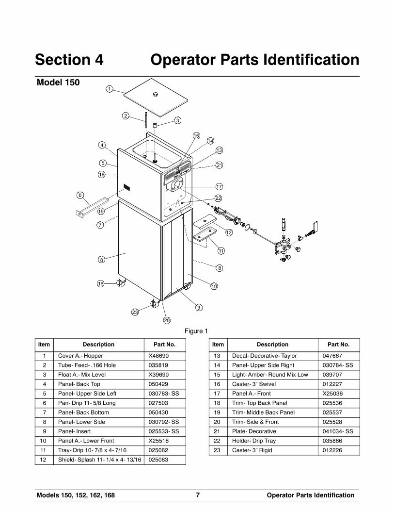
Section 4 Operator Parts IdentificationModel 150
Figure 1
Item Description Part No.
1 Cover A.- Hopper X48690
2 Tube- Feed- .166 Hole 035819
3 Float A.- Mix Level X39690
4 Panel- Back Top 050429
5 Panel- Upper Side Left 030783- SS
6 Pan- Drip 11- 5/8 Long 027503
7 Panel- Back Bottom 050430
8 Panel- Lower Side 030792- SS
9 Panel- Insert 025533- SS
10 Panel A.- Lower Front X25518
11 Tray- Drip 10- 7/8 x 4- 7/16 025062
12 Shield- Splash 11- 1/4 x 4- 13/16 025063
Item Description Part No.
13 Decal- Decorative- Taylor 047667
14 Panel- Upper Side Right 030784- SS
15 Light- Amber- Round Mix Low 039707
16 Caster- 3” Swivel 012227
17 Panel A.- Front X25036
18 Trim- Top Back Panel 025536
19 Trim- Middle Back Panel 025537
20 Trim- Side & Front 025528
21 Plate- Decorative 041034- SS
22 Holder- Drip Tray 035866
23 Caster- 3” Rigid 012226
8 Models 150, 152, 162, 168Operator Parts Identification
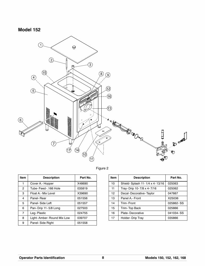
Model 152
Figure 2
Item Description Part No.
1 Cover A.- Hopper X48690
2 Tube- Feed- .166 Hole 035819
3 Float A.- Mix Level X39690
4 Panel- Rear 051556
5 Panel- Side Left 051557
6 Pan- Drip 11- 5/8 Long 027503
7 Leg- Plastic 024755
8 Light- Amber- Round Mix Low 039707
9 Panel- Side Right 051558
Item Description Part No.
10 Shield- Splash 11- 1/4 x 4- 13/16 025063
11 Tray- Drip 10- 7/8 x 4- 7/16 025062
12 Decal- Decorative- Taylor 047667
13 Panel A.- Front X25036
14 Trim- Front 025862- SS
15 Trim- Top Back 025866
16 Plate- Decorative 041034- SS
17 Holder- Drip Tray 035866

9Models 150, 152, 162, 168 Operator Parts Identification
Model 162
Figure 3
Item Description Part No.
1 Cover A.- Hopper X37963- SER
2 Tube- Feed- .166 Hole 030797
3 Float A.- Mix Level X39690
4 Panel- Rear 047276- SS
5 Panel- Side- Left 050213- SS
6 Pan- Drip 19- 1/2 Long 035034
7 Panel A.- Front X30711
8 Light- Amber- Round Mix Low 039707
9 Decal- Decorative- Taylor 047666
10 Shield- Splash 030789
Item Description Part No.
11 Tray- Drip- 16- 7/8 x 4- 3/8 030565
12 Panel- Front Right 035933- SS
13 Trim- Front 050212- SS
14 Panel- Front Left 035932- SS
15 Leg- 4.250” (With O- Ring) 013458
16 Panel- Side Right 050214- SS
17 Trim- Panel- Rear 035923
18 Plate- Decorative 039723- SS
19 Holder- Drip Tray 035866

10 Models 150, 152, 162, 168Operator Parts Identification
Model 168
Figure 4
Item Description Part No.
1 Cover A.- Hopper X37963- SER
2 Tube- Feed- .166 Hole SS 030797
3 Float A.- Mix Level X39690
4 Panel- Top Back 030790- SS
5 Panel- Upper Side Left 030783- SS
6 Pan- Drip 17- 1/4” Long 027504
7 Panel A.- Front X30711
8 Light- Amber- Round Mix Low 039707
9 Decal- Decorative- Taylor 047666
10 Shield- Splash 17- 5/8 Long 030789
11 Tray- Drip 16- 7/8 Long 030565
Item Description Part No.
12 Panel- Upper Side Right 030784- SS
13 Insert- Front Panel 030773- SS
14 Panel A.- Lower Front X30747
15 Panel- Bottom Back 055833
16 Caster- 3” Rigid (Rear) 012226
17 Caster- 3” Swivel (Front) 012227
18 Panel- Lower Side- Right/Left 030792- SS
19 Trim- Top Back Panel 030775
20 Trim- Middle Back Panel 030795
21 Plate- Decorative 039723- SS
22 Holder- Drip Tray 035866

11Models 150, 152, 162, 168 Operator Parts Identification
120501
Models 150 & 152 Door Assembly
Figure 5
Item Description Part No.
1 Valve- Draw 024763
2 O- Ring- 7/8 OD x .103 W 014402
3 O- Ring- 3/4 OD x .103 W 015835
4 Handle- Draw 024762
5 Arm- Valve Lifter 024761
6 Nut- Stud 034829
7 Cap- Design 1.010” ID - 6 Point 014218
Item Description Part No.
8 Door A.- 1 Spout X38959- SER
9 Bearing- Guide 014496
10 O- Ring- 2- 3/4 OD x .139 W 019998
11 Bearing- Front 023262
12 Beater A. X24689
13 Seal- U- Cup 080534

12 Models 150, 152, 162, 168Operator Parts Identification
120501
Models 162 & 168 Door Assembly
Figure 6
Item Description Part No.
1 Valve- Draw 024763
2 O- Ring- 7/8 OD x .103 W 014402
3 Seal- Draw Valve (H- Ring) 030930
4 Kit A.- Door 3 Spt 1.5 Qt. Valox X56906- SER
4a Nut- Stud 056802
5 Pin A.- Pivot Short X38539
6 O- Ring- 5/16 OD x .070 W 016272
7 Handle- Draw Valve 030564
Item Description Part No.
8 Cap- Design 1.010” ID - 6 Point 014218
9 Pin A.- Pivot Long X38538
10 Valve- Draw- Center 031164
11 Bearing- Guide 014496
12 O- Ring- 2- 3/4 OD x .139 W 019998
13 Bearing- Front 023262
14 Beater A. X24689
15 Seal- U- Cup 080534
13Models 150, 152, 162, 168 Operator Parts Identification
140806
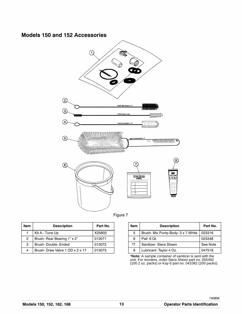
Models 150 and 152 Accessories
Figure 7
Item Description Part No.
1 Kit A.- Tune Up X25802
2 Brush- Rear Bearing 1” x 2” 013071
3 Brush- Double- Ended 013072
4 Brush- Draw Valve 1 OD x 2 x 17 013073
Item Description Part No.
5 Brush- Mix Pump Body- 3 x 7 White 023316
6 Pail- 6 Qt. 023348
*7 Sanitizer- Stera Sheen See Note
8 Lubricant- Taylor 4 Oz. 047518
*Note: A sample container of sanitizer is sent with theunit. For reorders, order Stera Sheen part no. 055492(100 2 oz. packs) or Kay-5 part no. 041082 (200 packs).

14 Models 150, 152, 162, 168Operator Parts Identification
110804
Models 162 and 168 Accessories
Figure 8
Item Description Part No.
1 Kit A.- Tune Up X31167
2 Brush- Rear Bearing 1” x 2” 013071
3 Brush- Double Ended 013072
4 Brush- Draw Valve 1” x 2” x 17” 013073
Item Description Part No.
5 Brush- Mix Pump Body- 3” x 7” 023316
6 Pail- 6 Qt. 023348
*7 Sanitizer See Note
8 Lubricant- Taylor 4 Oz. 047518
*Note: A sample container of sanitizer is sent with theunit. For reorders, order Stera Sheen part no. 055492(100 2 oz. packs) or Kay-5 part no. 041082 (200 packs).

15Models 150, 152, 162, 168 Important: To the Operator
Section 5 Important: To the Operator
Figure 9
Item Description
1 Reset Button2 Power Switch3 Temperature Control4 Mix Refrigeration Switch5 Indicator Lights - “Mix Low”
Symbol DefinitionsTo better communicate in the International arena, thewords on many of our operator switches and buttonshave symbols to indicate their functions. Your Taylorequipment is designed with these Internationalsymbols.
The following chart identifies the symbol definitionsused on the operator switches.
= ON/AUTO key
= ON key
= OFF key
= WASH key
= STANDBY key
16 Models 150, 152, 162, 168Important: To the Operator
090526
Reset Button
If an overload condition occurs, the freezer willautomatically stop operating. To properly reset thefreezer, place the toggle switch in the “OFF” position.Wait two or three minutes; then press the reset button.Place the power switch in the “WASH” position andobserve the freezer’s performance; place the powerswitch in the “AUTO” position.
Note: If the freezer is unplugged from the wallreceptacle, it will be necessary to press the resetbutton for the freezer to operate once power isre- established.
Power Switch
The center position is “OFF”. The left position is“WASH” which activates the beater motor only. Theright position is “AUTO”, which activates the beatermotor and the refrigeration system.
Feed Tube
The models 150, 152, 162 and 168 are called upon tohandle a large variety of products (i.e., soft serve,yogurts, Italian ices, sherbets, etc.). Thus, theconsistency of the mix you usewill vary. The feed tubemeters a combination of mix and air into the freezingcylinder. If not enoughmix enters the freezing cylinder,a freeze- up may occur, which will cause eventualdamage to the beater. Depending upon the productbeing run, you may wish to contact your localauthorized Taylor Distributor to make a slightadjustment in the feed tube.
Figure 10
Note: During “AUTO” operation, the orifice end of thetube should be inserted in the hole in the hopper.
Taylor Quality Control
These units use a solid state control called the T.Q.C.The purpose of this solid state control is to sense theviscosity (thickness) of the product in the freezingcylinder. With the power switch in the “AUTO” position,the T.Q.C. will automatically keep the mix in thefreezing cylinder at the proper viscosity and ready forserving.
Indicator Light - “Mix Low”
A mix level indicating light is located at the front of theunit. When the light is on, it indicates that the mixhopper has a low supply of mix and should be refilledas soon as possible. Always maintain at least 2” (5.1cm) of mix in the hopper. If you neglect to add mix, afreeze- up may occur. This will cause eventualdamage to the beater assembly and to the freezerdoor.
Mix Refrigeration SwitchThe mix refrigeration switch is located under thecontrol channel and is used for several purposes:
1. For the unit to operate in the “AUTO” mode, themix refrigeration switch must be “ON”.
2. For the separate hopper refrigeration system tooperate, the mix refrigeration switch must be inthe “ON” or the “STANDBY” position.
3. For the cylinder temperature retention system tooperate, the power switch must be in the “AUTO”position and the mix refrigeration switch must bein the “STANDBY” position.
Separate Hopper Refrigeration(SHR)This feature incorporates the use of a separate smallrefrigeration system to chill (on a limited basis) and tomaintain the mix in the hopper to under 40_F (4.4_C)and assures bacterial control. To activate this system,place the power switch in the “AUTO” position and themix refrigeration switch in the “ON” position. To oper-ate this system in the “STANDBY” mode, place thepower switch in the “AUTO” position and the mix refri-geration switch in the “STANDBY” position.
17Models 150, 152, 162, 168 Important: To the Operator
Cylinder Temperature Retention(CTR)
To maintain a good quality product during long “NoSale” periods, it will be necessary to warm the productin the freezing cylinder to approximately 35_ to 40_F(1.7_ to 4.4_C). This will prevent overbeating andproduct breakdown. The CTR is used in conjunctionwith the SHR to insure that the mix in the freezingcylinder is refrigerated during the “STANDBY”modeofoperation.
To operate the “STANDBY” mode of operation:
Place the power switch in the “AUTO” position and themix refrigeration switch in the “STANDBY” position.With sanitized hands, remove the feed tube. Turn itover and place the end without the hole into the mixinlet hole.
To resume normal operation:
Leave the power switch in the “AUTO” position andplace the mix refrigeration switch in the “AUTO”position. When the unit cycles off, the product in thefreezing cylinder will be the correct viscosity. Withsanitized hands, remove the feed tube. Turn it overand place the end with the hole into the mix inlet hole.

18 Models 150, 152, 162, 168Operating Procedures
120501
Section 6 Operating Procedures
The Model 150 has been selected to illustrate thepictured step- by- step operating procedures. Allmodels in this manual are similar. They each have a1.5 quart (1.4 liter) capacity freezing cylinder. The mixflows by gravity from the hopper to the freezingcylinder through an feed tube.
The Model 150 is a console model with a single spoutdoor.
The Model 152 is a counter model with a single spoutdoor.
The Model 162 is a counter model and the Model 168is a console model. Both have three spout doors. Twoindividual flavors are available from the end spouts,andanequal combination of both is dispensed throughthe center spout to create a twist effect.
For the Models 162 and 168, duplicate the procedureswhere they apply for the second freezing cylinder.
We begin our instructions at the point where we enterthe store in the morning and find the partsdisassembled and laid out to air dry from the previousnight’s cleaning.
These opening procedures will show you how toassemble these parts into the freezer, sanitize them,and prime the freezer with fresh mix in preparation toserve your first portion.
Figure 11
Figure 12
Figure 13
Figure 14
If you are disassembling the machine for the first timeor need information to get to the starting point in ourinstructions, turn to page 26, “Disassembly”, and startthere.

19Models 150, 152, 162, 168 Operating Procedures
150105
Assembly
MAKE SURE THE POWER SWITCH IS INTHE “OFF” POSITION. Failure to follow thisinstruction may result in electrocution or injury tofingers or hands from hazardous moving parts.
Note: When lubricating parts, use an approved foodgrade lubricant (example: Taylor Lube).
Step 1Lubricate thegrooveon thebeater drive shaft.With theopening of the cup seal facing away from the hex end,slide the seal into the groove. Apply an even coat oflubricant to the seal and the shaft. Do notlubricate the hex end of the beater drive shaft.
Figure 15
Step 2Insert the beater assembly through the rear shellbearingat theback of the freezing cylinder andengagethe hex end firmly into the female socket. Whenproperly seated, the beater will not protrude beyondthe front of the freezing cylinder.
Figure 16
Repeat this step for the second freezing cylinder onModels 162/168.
Step 3Place the largeo- ring(s) into thegroove(s) on thebackof the freezer door and lubricate with Taylor Lube.
Figure 17
Step 4Slide the front bearing(s) over the baffle rod(s) so theflanged edge is against the door. Place the whiteplastic guide bearing(s) on the end of the baffle rod(s).
Do not lubricate the front bearing(s) or the guidebearing(s).
Figure 18
Step 5Slide the slotted portion of the handscrews into theslots in the freezer door.
Step 6With both hands, hold the sides of the freezer door andinsert the baffle rod(s) into the center of the beaterassembly(ies). The white guide bearing(s) must fitsecurely in the hole(s) of the drive shaft(s).

20 Models 150, 152, 162, 168Operating Procedures
150105
Step 7Finger- tighten the handscrews, making sure they aretightened equally and that the door is snug. Do notover- tighten the handscrews.
IMPORTANT! Handscrew and door damage canresult if the handscrews are over- tightened or ifone handscrew is tightened more than the other.
Step 8Slide the two o- rings into the grooves on the drawvalve(s) and lubricate with Taylor Lube.
Figure 19
Note: For the Models 162/168, install the valve sealin the grooves on the center draw valve and lubricatewith Taylor Lube. This special seal will prevent mixfrom one freezing cylinder from traveling into thesecond cylinder.
Figure 20
Step 9Lubricate the inside of the freezer door spout(s) fromthe bottom. Insert the draw valve(s) into the freezerdoor from the bottom.
Figure 21
Note: The draw valve is installed correctly when theslotted opening in the draw valve is visible through the“window” of the freezer door.
Figure 22
Step 10Slide the o- ring into the groove on the draw valvehandle and lubricate with Taylor Lube.
Figure 23

21Models 150, 152, 162, 168 Operating Procedures
150105
Step 11Insert the valve lifter arm through the slotted openingin the draw valve and align the other endwith the crossholes of the freezer door.
Step 12Insert the draw valve handle through the oppositecross hole and into the opening of the valve lifter arm.
Hint: The draw valve handle can be assembled atvaried vertical positions. Choose an angle which iscomfortable for you. The draw valve must be raisedcompletely when the draw valve handle is down.
Figure 24
Note: ForModels 162/168, slide the o- ring onto eachpivot pin and lubricate with Taylor Lube.
Figure 25
Note: Models 162/168 have three draw handles.Slide the tip of the draw handle into the slot of the drawvalve, starting from the right. Slide the short pivot pinthrough the far right draw handle. Slide the long pivotpin through the far left and middle draw handles.
Figure 26
Step 13Snap the design cap(s) over the bottom of the freezerdoor spout(s).
Figure 27
Step 14Install the front drip tray and splash shield under thefreezer door.
Figure 28

22 Models 150, 152, 162, 168Operating Procedures
Step 15Lay the feed tube(s) in thebottom of themix hopper(s).
Sanitizing
Step 1Prepare an approved 100 PPM sanitizing solution (ex-amples: Kay- 5R or Stera- SheenR). USE WARMWATER AND FOLLOW THE MANUFACTURER’SSPECIFICATIONS.
Step 2Pour one gallon (3.8 liters) of the sanitizing solutioninto the hopper and allow it to flow into the freezingcylinder.
Step 3While the solution is flowing into the freezing cylinder,brush- clean the mix hopper, mix level float stem, mixinlet hole, and feed tube.
Figure 29
Figure 30
Figure 31
Step 4Press the reset button.
Figure 32
Step 5Place the power switch in the “WASH” position. Thiswill cause the sanitizing solution in the freezingcylinder to be agitated. Allow it to agitate for fiveminutes.
Figure 33

23Models 150, 152, 162, 168 Operating Procedures
Step 6Place an empty pail beneath the door spout and raisethe draw valve. Draw off all of the sanitizing solution.When the sanitizer stops flowing from the door spout,lower the draw valve and place the power switch in the“OFF” position.
Figure 34
Note: OnModels 162/168, momentarily pull down thecenter draw handle to sanitize the center door spout.
Step 7With sanitized hands, stand the feed tube in thecorner of the mix hopper. Place the mix level float onthe mix level float stem.
Figure 35
Repeat Steps 1 through 7 for the second freezingcylinder on Models 162/168.
Priming
Prime the machine as close as possible to the time offirst product draw.
Step 1With a pail beneath the door spout, raise the drawvalve. Fill the mix hopper with fresh mix. (Maximumhopper capacity is 8 quarts [7.6 liters].) Allow the mixto flow into the freezing cylinder. This will force out anyremaining sanitizing solution.When full strength mix isflowing from the door spout, lower the draw valve.
Note: Use only FRESH mix when priming thefreezer.
Figure 36
Step 2When the mix has stopped bubbling down into thefreezing cylinder, with sanitized hands, install thefeed tube in themix inlet hole.Make sure the small holein the feed tube is down.
Figure 37

24 Models 150, 152, 162, 168Operating Procedures
150105
Step 3Place the mix hopper cover in position.
Step 4Place the mix refrigeration switch in the “ON” position.
Figure 38
Step 5Place the power switch in the “AUTO” position.
Figure 39
Step 6Momentarily raise the draw switch paddle to activatethe refrigeration cycle. When the unit cycles off, theproduct will be ready to serve.
Repeat the applicable steps for the second freezingcylinder on Models 162/168.
Step 7Slide the rear drip pan into the hole in the side panel.
Figure 40
Closing Procedure
To disassemble the Models 150/152/162/168, thefollowing items will be needed:
S Two cleaning pails
S Sanitized stainless steel rerun can with lid
S Necessary brushes (provided with freezer)
S Cleaner
S Single service towels

25Models 150, 152, 162, 168 Operating Procedures
140721
Draining Product From theFreezing Cylinder
Step 1Place themix refrigeration switch and thepowerswitchin the “OFF” position as far ahead of cleaning time aspossible. This will allow frozen product to soften foreasier cleaning.
Step 2If local health codes permit the use of rerun, placea sanitized, NSF approved stainless steel reruncontainer beneath the door spout. Place the powerswitch in the “WASH” position and raise the drawvalve.Whenall the product stops flowing from thedoorspout, lower thedrawvalveandplace thepowerswitchin the “OFF” position. Place a sanitized lid on the reruncontainer and place it in the walk- in cooler.(Note: For additional information regarding the properuse of rerun, see item 5 on page 27.)
Note: If local health codesDONOTpermit theuseof rerun, the productmust bediscarded. Follow theinstructions in the previous step, except drain theproduct into a pail and properly discard the mix.
ALWAYS FOLLOW LOCAL HEALTH CODES.
Step 3Lift the hopper cover. Remove the feed tube and mixlevel float. Take them to the sink for cleaning.
Repeat Steps 1 through 3 for the second freezingcylinder on Models 162/168.
Rinsing
Step 1Pour onegallon (3.8 liters) of cool, cleanwater into themix hopper. With the brushes provided, scrub the mixhopper, the mix level float stem and the mix inlet hole.
Step 2With a pail beneath the door spout, place the powerswitch in the “WASH” position and raise the drawvalve. Drain all the rinse water from the freezingcylinder. When the rinse water stops flowing from thedoor spout, lower the draw valve and place the powerswitch in the “OFF” position.
Repeat this procedure until the rinse water beingdrawn from the freezing cylinder is clear.
Repeat Steps 1 and 2 for the second freezing cylinderon Models 162/168.
Cleaning
Step 1Prepare an approved cleaning solution (examples:Kay- 5R or Stera- SheenR). USE WARM WATERANDFOLLOWTHEMANUFACTURER’SSPECIFIC-ATIONS.
Step 2Pour one gallon (3.8 liters) of the cleaning solution intothe mix hopper and allow it to flow into the freezingcylinder.
Step 3While the solution is flowing into the freezing cylinder,brush- clean the mix hopper, mix level float stem andmix inlet hole.
Step 4Place the power switch in the “WASH” position. Thiswill cause the cleaning solution in the freezing cylinderto agitate.
Step 5Place an empty pail beneath the door spout and raisethe draw valve. Draw off all the cleaning solution.When the solution stops flowing from the door spout,lower the draw valve and place the power switch in the“OFF” position.
Repeat Steps 1 through 5 for the other side of thefreezer on Models 162/168.

26 Models 150, 152, 162, 168Operating Procedures
150105
Disassembly
MAKE SURE THE POWER SWITCH IS INTHE “OFF” POSITION. Failure to follow thisinstruction may result in electrocution or injury tofingers or hands from hazardous moving parts.
Step 1Remove the handscrews and the freezer door.Remove the beater assembly(ies) from the freezingcylinder(s).
Step 2Remove the front drip tray and the splash shield.
Step 3Remove the rear drip pan from the side panel.
Note: If the drip pan is filled with an excessive amountof mix, this is an indication that the drive shaft cup sealof the beater assembly should be replaced or properlylubricated.
Step 4Take these parts to the sink for cleaning.
Brush Cleaning
Step 1Prepare a sink with an approved cleaning solution(examples: Kay- 5R or Stera- SheenR). USEWARMWATER AND FOLLOW THE MANUFACTURER’SSPECIFICATIONS.
IMPORTANT: Follow label directions, as tooSTRONG of a solution can cause parts damage, whiletoo MILD of a solution will not provide adequatecleaning.) Make sure all brushes provided with thefreezer are available for brush cleaning.
Step 2Remove the cup seal(s) from the drive shaft(s) of thebeater assembly(ies).
Step 3From the freezer door, remove the design cap, drawvalvehandle, valve lifter arm, anddraw valve. Removeall o- rings.
Models 162/168: From the freezer door, removedesign caps, pivot pins, draw handles, draw valves,and the center draw valve. Remove all o- rings.
Note: To remove the o- rings, use a single servicetowel to grasp the o- ring. Apply pressure in an upwarddirection until the o- ring pops out of its groove. Withthe other hand, push the top of the o- ring forward, andit will roll out of the groove and can be easily removed.If there is more than one o- ring to be removed, alwaysremove the rear o- ring first. This will allow the o- ringto slide over the forward rings without falling into theopen grooves.
Step 4Remove the front bearing(s), and guide bearing(s)from the back of the freezer door.
Step 5Thoroughly brush clean all disassembled parts in thecleaning solution. Make sure all lubricant and mix filmis removed. Take particular care to brush clean thedraw valve core(s) in the freezer door. Place all thecleaned parts on a clean, dry surface to air dryovernight.
Step 6Return to the freezer with a small amount of cleaningsolution. With the black bristle brush, brush clean therear shell bearing(s) at the back of the freezingcylinder(s).
Figure 41
Step 7Wipe clean all exterior surfaces of the freezer.

27Models 150, 152, 162, 168 Important: Operator Checklist
Section 7 Important: Operator Checklist
During Cleaning and Sanitizing
ALWAYS FOLLOW LOCAL HEALTH CODES.
Cleaning and sanitizing schedules are governedby federal, state, or local regulatory agencies, andmust be followed accordingly. If the unit has a“Standby mode”, it must not be used in lieu ofproper cleaning and sanitizing procedures andfrequencies set forth by the ruling healthauthority. The following check points should bestressed during the cleaning and sanitizingoperations.
CLEANING AND SANITIZING MUST BEPERFORMED DAILY.
Troubleshooting Bacterial Count
j 1. Thoroughly clean and sanitize the machineregularly, including complete disassembly andbrush cleaning.
j 2. Use all brushes supplied for thorough cleaning.The brushes are specially designed to reach allmix passageways.
j 3. Use the smaller, white bristle brush to clean themix inlet hole which extends from the mixhopper down to the rear of the freezing cylinder.
j 4. Use the black bristle brush to thoroughly cleanthe rear shell bearing located at the rear of thefreezing cylinder. Be sure to have a generousamount of cleaning solution on the brush.
j 5. IF LOCAL HEALTH CODES PERMIT THEUSE OF RERUN, make sure the mix rerun isstored in a sanitized, covered stainless steelcontainer and is used the following day. DONOT prime themachinewith rerun.When usingrerun, skim off the foam and discard. Mix thererunwith freshmix in a ratio of 50/50 during theday’s operation.
j 6. On a designated day of theweek, run themix aslow as feasible and discard after closing. Thiswill break the rerun cycle and reduce thepossibility of high bacteria and coliform counts.
j 7. Properly prepare the cleaning and sanitizingsolutions. Read and follow label directionscarefully. Too strong of a solution may damagethe parts and too weak of a solution will not doan adequate job of cleaning or sanitizing.
j 8. The temperature of the mix in the mix hopperand walk- in cooler should be below 40_F.(4.4_C.).
Regular Maintenance Checks
j 1. Check the rear shell bearing for signs of wear(excessive mix leakage in rear drip pan) and becertain it is properly cleaned.
j 2. Using a screwdriver and cloth towel, keep therear shell bearing and the female hex drivesocket clean and free of lubricant and mixdeposits.
j 3. Dispose of o- rings or seals if they are worn,torn, or fit too loosely, and replace with newones.
j 4. Follow all lubricating procedures as outlined in“Assembly”.

28 Models 150, 152, 162, 168Important: Operator Checklist
j 5. If your machine is air cooled, check thecondenser for an accumulation of dirt and lint.A dirty condenser will reduce the efficiency andcapacity of themachine. Condensers should becleaned monthly with a soft brush. Never usescrewdrivers or other metal probes to cleanbetween the fins. Failure to comply may resultin electrocution.Note: For machines equipped with an air filter,it will be necessary to vacuum clean the filterson a monthly schedule.
j 6. On the auxiliary refrigeration system, check thecondenser for accumulation of dirt and lint. Adirty condenser will reduce the refrigerationcapacity of the mix hopper. Condensers mustbe cleaned monthly with a soft brush. Neveruse screwdrivers or other metal probes to cleanbetween the fins. Failure to comply may resultin electrocution.
Winter Storage
If the placeof business is to be closedduring thewintermonths, it is important to protect the freezer byfollowing certain precautions, particularly if thebuilding is subject to freezing conditions.
Disconnect the freezer from the main power source toprevent possible electrical damage.
Your local Taylor distributor canperform this service foryou.
Wrap detachable parts of the freezer such as thebeater assembly and freezer door, and place them ina protected dry place. Rubber trim parts and gasketscan be protected by wrapping them withmoisture- proof paper. All parts should be thoroughlycleaned of dried mix or lubrication accumulationswhich attract mice and other vermin.
29Models 150, 152, 162, 168 Troubleshooting Guide
Section 8 Troubleshooting Guide
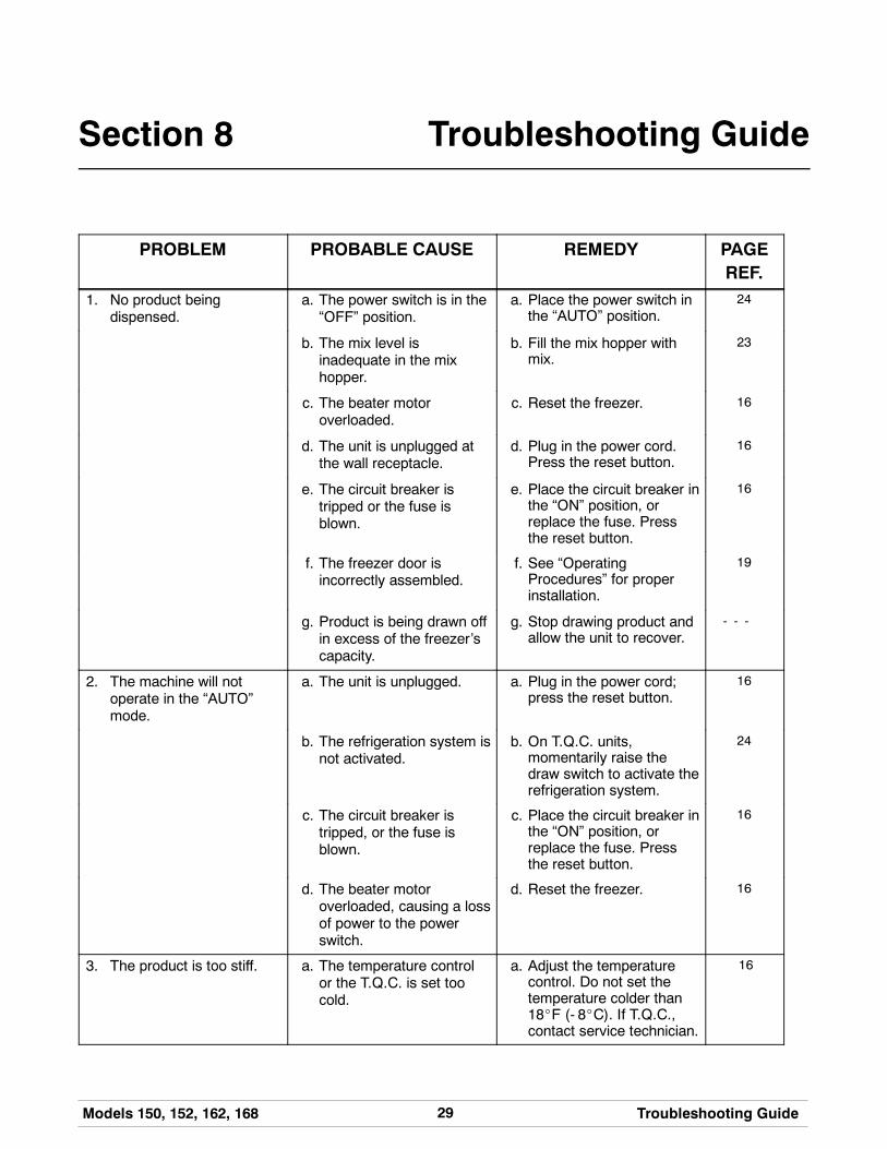
PROBLEM PROBABLE CAUSE REMEDY PAGEREF.
1. No product beingdispensed.
a. The power switch is in the“OFF” position.
a. Place the power switch inthe “AUTO” position.
24
b. The mix level isinadequate in the mixhopper.
b. Fill the mix hopper withmix.
23
c. The beater motoroverloaded.
c. Reset the freezer. 16
d. The unit is unplugged atthe wall receptacle.
d. Plug in the power cord.Press the reset button.
16
e. The circuit breaker istripped or the fuse isblown.
e. Place the circuit breaker inthe “ON” position, orreplace the fuse. Pressthe reset button.
16
f. The freezer door isincorrectly assembled.
f. See “OperatingProcedures” for properinstallation.
19
g. Product is being drawn offin excess of the freezer’scapacity.
g. Stop drawing product andallow the unit to recover.
- - -
2. The machine will notoperate in the “AUTO”mode.
a. The unit is unplugged. a. Plug in the power cord;press the reset button.
16
b. The refrigeration system isnot activated.
b. On T.Q.C. units,momentarily raise thedraw switch to activate therefrigeration system.
24
c. The circuit breaker istripped, or the fuse isblown.
c. Place the circuit breaker inthe “ON” position, orreplace the fuse. Pressthe reset button.
16
d. The beater motoroverloaded, causing a lossof power to the powerswitch.
d. Reset the freezer. 16
3. The product is too stiff. a. The temperature controlor the T.Q.C. is set toocold.
a. Adjust the temperaturecontrol. Do not set thetemperature colder than18_F (- 8_C). If T.Q.C.,contact service technician.
16
30 Models 150, 152, 162, 168Troubleshooting Guide
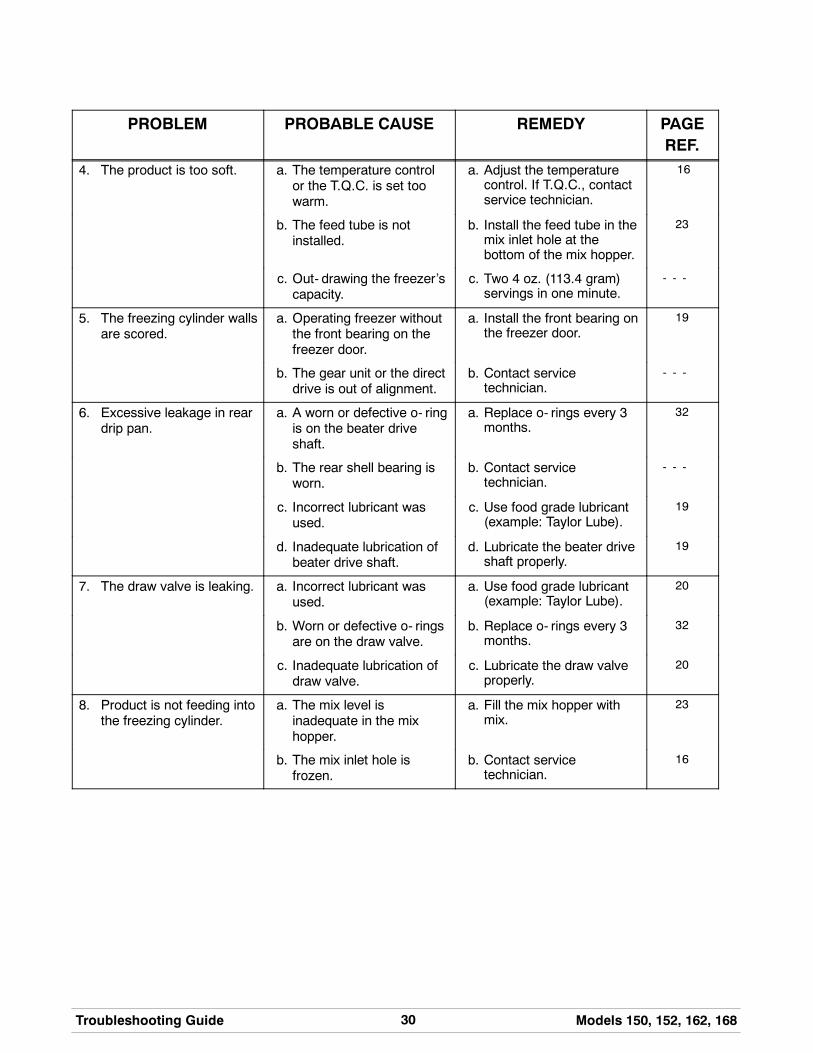
PROBLEM PROBABLE CAUSE REMEDY PAGEREF.
4. The product is too soft. a. The temperature controlor the T.Q.C. is set toowarm.
a. Adjust the temperaturecontrol. If T.Q.C., contactservice technician.
16
b. The feed tube is notinstalled.
b. Install the feed tube in themix inlet hole at thebottom of the mix hopper.
23
c. Out- drawing the freezer’scapacity.
c. Two 4 oz. (113.4 gram)servings in one minute.
- - -
5. The freezing cylinder wallsare scored.
a. Operating freezer withoutthe front bearing on thefreezer door.
a. Install the front bearing onthe freezer door.
19
b. The gear unit or the directdrive is out of alignment.
b. Contact servicetechnician.
- - -
6. Excessive leakage in reardrip pan.
a. A worn or defective o- ringis on the beater driveshaft.
a. Replace o- rings every 3months.
32
b. The rear shell bearing isworn.
b. Contact servicetechnician.
- - -
c. Incorrect lubricant wasused.
c. Use food grade lubricant(example: Taylor Lube).
19
d. Inadequate lubrication ofbeater drive shaft.
d. Lubricate the beater driveshaft properly.
19
7. The draw valve is leaking. a. Incorrect lubricant wasused.
a. Use food grade lubricant(example: Taylor Lube).
20
b. Worn or defective o- ringsare on the draw valve.
b. Replace o- rings every 3months.
32
c. Inadequate lubrication ofdraw valve.
c. Lubricate the draw valveproperly.
20
8. Product is not feeding intothe freezing cylinder.
a. The mix level isinadequate in the mixhopper.
a. Fill the mix hopper withmix.
23
b. The mix inlet hole isfrozen.
b. Contact servicetechnician.
16

31Models 150, 152, 162, 168 Troubleshooting Guide
PROBLEM PROBABLE CAUSE REMEDY PAGEREF.
9. The unit goes out onoverload excessively.
a. There are too manyappliances plugged intothe circuit.
a. A separate 20 amp.circuit is needed for thefreezer to operateproperly.
- - -
b. An extension cord hasbeen placed between thepower cord and the wallreceptacle.
b. If the extension cord isused, it must match thepower cord in size ofcircuit ampacity.
- - -
10. Models 162 and 168:Mix from one freezingcylinder bleeds over to thesecond cylinder.
a. The center draw valveseal is worn, or isimproperly lubricated.
a. Lubricate properly andreplace seal every 3months.
20 / 32
32 Models 150, 152, 162, 168Parts Replacement Schedule
120501
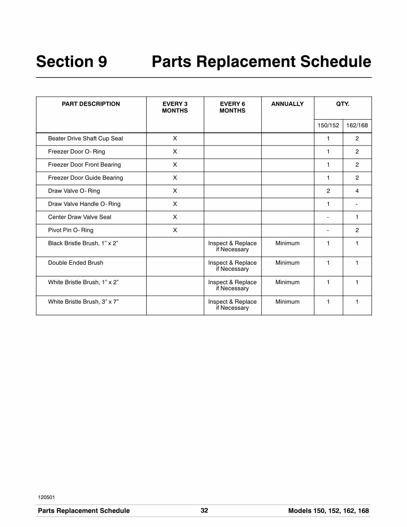
Section 9 Parts Replacement Schedule
PART DESCRIPTION EVERY 3MONTHS
EVERY 6MONTHS
ANNUALLY QTY.
150/152 162/168
Beater Drive Shaft Cup Seal X 1 2
Freezer Door O- Ring X 1 2
Freezer Door Front Bearing X 1 2
Freezer Door Guide Bearing X 1 2
Draw Valve O- Ring X 2 4
Draw Valve Handle O- Ring X 1 -
Center Draw Valve Seal X - 1
Pivot Pin O- Ring X - 2
Black Bristle Brush, 1” x 2” Inspect & Replaceif Necessary
Minimum 1 1
Double Ended Brush Inspect & Replaceif Necessary
Minimum 1 1
White Bristle Brush, 1” x 2” Inspect & Replaceif Necessary
Minimum 1 1
White Bristle Brush, 3” x 7” Inspect & Replaceif Necessary
Minimum 1 1

33Models 150, 152, 162, 168 Limited Warranty on Equipment
131122
Section 10 Limited Warranty on Equipment
TAYLOR COMPANY LIMITED WARRANTY ON FREEZERS
Taylor Company, a division of Carrier Commercial Refrigeration, Inc. (“Taylor”) is pleased to provide this limitedwarranty on new Taylor-branded freezer equipment available from Taylor to the market generally (the “Product”)to the original purchaser only.
LIMITED WARRANTY
Taylor warrants the Product against failure due to defect in materials or workmanship under normal use andservice as follows. All warranty periods begin on the date of original Product installation. If a part fails due todefect during the applicable warranty period, Taylor, through an authorized Taylor distributor or service agency,will provide a new or re- manufactured part, at Taylor’s option, to replace the failed defective part at no charge forthe part. Except as otherwise stated herein, these are Taylor’s exclusive obligations under this limited warranty fora Product failure. This limited warranty is subject to all provisions, conditions, limitations and exclusions listedbelow and on the reverse (if any) of this document.
Product Part Limited Warranty Period
Soft ServeFrozen YogurtShakesSmoothies
Frozen BeverageBatch Desserts
Insulated shell assembly Five (5) years
Refrigeration compressor(except service valve)
Five (5) years
Beater motors Two (2) years
Beater drive gear Two (2) years
Printed circuit boards andSoftech controls beginningwith serial number H8024200
Two (2) years
Parts not otherwise listed inthis table or excluded below
One (1) year
LIMITED WARRANTY CONDITIONS
1. If the date of original installation of the Product cannot be verified, then the limited warranty period beginsninety (90) days from the date of Product manufacture (as indicated by the Product serial number). Proof ofpurchase may be required at time of service.
2. This limited warranty is valid only if the Product is installed and all required service work on the Product isperformed by an authorized Taylor distributor or service agency, and only if genuine, new Taylor parts areused.
3. Installation, use, care, and maintenance must be normal and in accordance with all instructions contained inthe Taylor Operator’s Manual.
4. Defective parts must be returned to the authorized Taylor distributor or service agency for credit.
5. The use of any refrigerant other than that specified on the Product’s data label will void this limited warranty.
LIMITED WARRANTY EXCEPTIONS
This limited warranty does not cover:
1. Labor or other costs incurred for diagnosing, repairing, removing, installing, shipping, servicing or handling ofdefective parts, replacement parts, or new Products.
2. Normal maintenance, cleaning and lubrication as outlined in the Taylor Operator’s Manual, including cleaningof condensers.

34 Models 150, 152, 162, 168Limited Warranty on Equipment
3. Replacement of wear items designated as Class “000” parts in the Taylor Operator’s Manual.
4. External hoses, electrical power supplies, and machine grounding.
5. Parts not supplied or designated by Taylor, or damages resulting from their use.
6. Return trips or waiting time required because a service technician is prevented from beginning warrantyservice work promptly upon arrival.
7. Failure, damage or repairs due to faulty installation, misapplication, abuse, no or improper servicing,unauthorized alteration or improper operation or use as indicated in the Taylor Operator’s Manual, includingbut not limited to the failure to use proper assembly and cleaning techniques, tools, or approved cleaningsupplies.
8. Failure, damage or repairs due to theft, vandalism, wind, rain, flood, high water, water, lightning, earthquakeor any other natural disaster, fire, corrosive environments, insect or rodent infestation, or other casualty,accident or condition beyond the reasonable control of Taylor; operation above or below the electrical orwater supply specification of the Product; or components repaired or altered in any way so as, in thejudgment of the Manufacturer, to adversely affect performance, or normal wear or deterioration.
9. Any Product purchased over the Internet.
10. Failure to start due to voltage conditions, blown fuses, open circuit breakers, or damages due to theinadequacy or interruption of electrical service.
11. Electricity or fuel costs, or increases in electricity or fuel costs from any reason whatsoever.
12. Damages resulting from the use of any refrigerant other than that specified on the Product’s data label willvoid this limited warranty.
13. Any cost to replace, refill or dispose of refrigerant, including the cost of refrigerant.
14. ANY SPECIAL, INDIRECT OR CONSEQUENTIAL PROPERTY OR COMMERCIAL DAMAGE OF ANYNATURE WHATSOEVER. Some jurisdictions do not allow the exclusion of incidental or consequentialdamages, so this limitation may not apply to you.
This limited warranty gives you specific legal rights, and you may also have other rights which vary fromjurisdiction to jurisdiction.
LIMITATION OF WARRANTY
THIS LIMITED WARRANTY IS EXCLUSIVE AND IS IN LIEU OF ALL OTHER WARRANTIES, CONDITIONSAND/OR REMEDIES UNDER THE LAW, INCLUDING ANY IMPLIED WARRANTIES OR CONDITIONS OFMERCHANTABILITY OR FITNESS FOR A PARTICULAR PURPOSE. THE ORIGINAL OWNER’S SOLEREMEDY WITH RESPECT TO ANY PRODUCTS SHALL BE REPAIR OR REPLACEMENT OF DEFECTIVECOMPONENTS UNDER THE TERMS OF THIS LIMITED WARRANTY. ALL RIGHTS TO CONSEQUENTIALOR INCIDENTAL DAMAGES (INCLUDING CLAIMS FOR LOST SALES, LOST PROFITS, PRODUCT LOSS,PROPERTY DAMAGES OR SERVICE EXPENSES) ARE EXPRESSLY EXCLUDED. THE EXPRESSWARRANTIES MADE IN THIS LIMITED WARRANTY MAY NOT BE ALTERED, ENLARGED, OR CHANGEDBY ANY DISTRIBUTOR, DEALER, OR OTHER PERSON, WHATSOEVER.
LEGAL REMEDIES
The owner must notify Taylor in writing, by certified or registered letter to the following address, of any defect orcomplaint with the Product, stating the defect or complaint and a specific request for repair, replacement, or othercorrection of the Product under warranty, mailed at least thirty (30) days before pursuing any legal rights orremedies.
Taylor Companya division of Carrier Commercial Refrigeration, Inc.
750 N. Blackhawk Blvd.Rockton, IL 61072, U.S.A.
35Models 150, 152, 162, 168 Limited Warranty on Parts
131122
Section 11 Limited Warranty on Parts
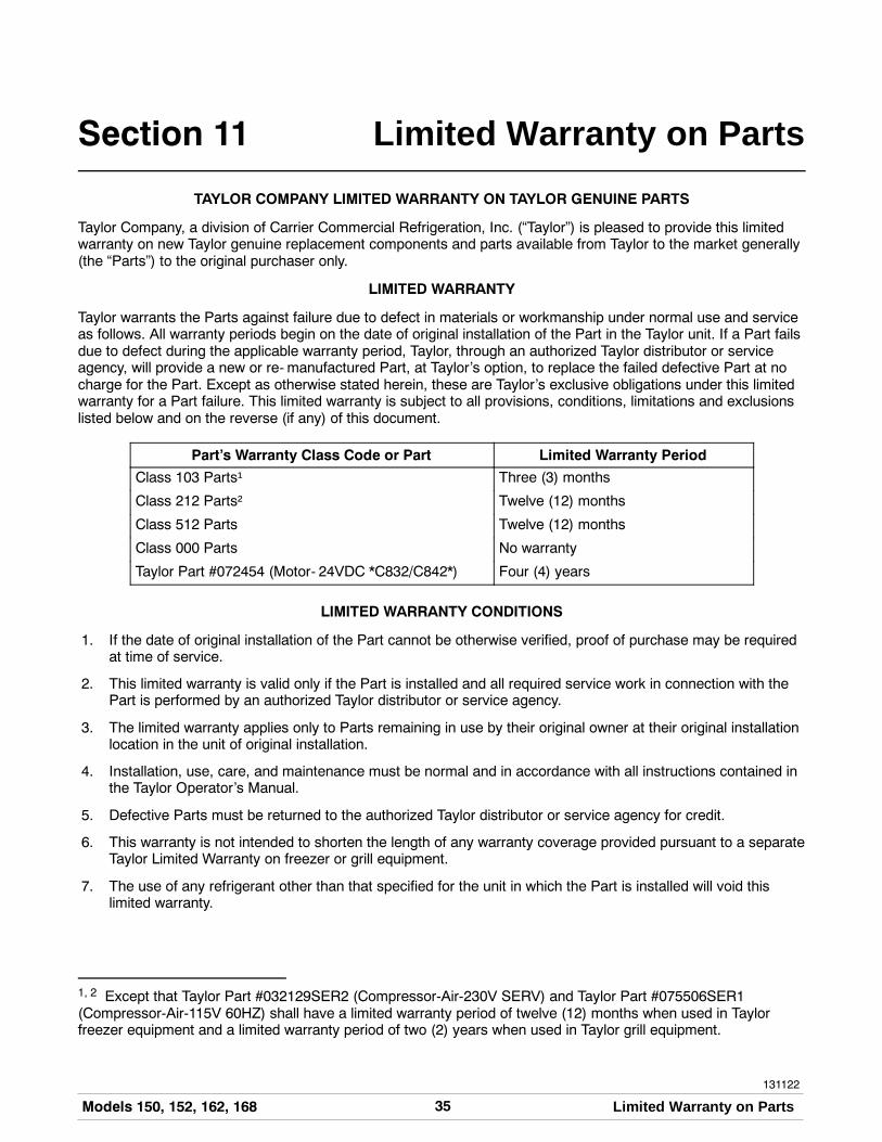
TAYLOR COMPANY LIMITED WARRANTY ON TAYLOR GENUINE PARTS
Taylor Company, a division of Carrier Commercial Refrigeration, Inc. (“Taylor”) is pleased to provide this limitedwarranty on new Taylor genuine replacement components and parts available from Taylor to the market generally(the “Parts”) to the original purchaser only.
LIMITED WARRANTY
Taylor warrants the Parts against failure due to defect in materials or workmanship under normal use and serviceas follows. All warranty periods begin on the date of original installation of the Part in the Taylor unit. If a Part failsdue to defect during the applicable warranty period, Taylor, through an authorized Taylor distributor or serviceagency, will provide a new or re- manufactured Part, at Taylor’s option, to replace the failed defective Part at nocharge for the Part. Except as otherwise stated herein, these are Taylor’s exclusive obligations under this limitedwarranty for a Part failure. This limited warranty is subject to all provisions, conditions, limitations and exclusionslisted below and on the reverse (if any) of this document.
Part’s Warranty Class Code or Part Limited Warranty Period
Class 103 Parts¹ Three (3) months
Class 212 Parts² Twelve (12) months
Class 512 Parts Twelve (12) months
Class 000 Parts No warranty
Taylor Part #072454 (Motor- 24VDC *C832/C842*) Four (4) years
LIMITED WARRANTY CONDITIONS
1. If the date of original installation of the Part cannot be otherwise verified, proof of purchase may be requiredat time of service.
2. This limited warranty is valid only if the Part is installed and all required service work in connection with thePart is performed by an authorized Taylor distributor or service agency.
3. The limited warranty applies only to Parts remaining in use by their original owner at their original installationlocation in the unit of original installation.
4. Installation, use, care, and maintenance must be normal and in accordance with all instructions contained inthe Taylor Operator’s Manual.
5. Defective Parts must be returned to the authorized Taylor distributor or service agency for credit.
6. This warranty is not intended to shorten the length of any warranty coverage provided pursuant to a separateTaylor Limited Warranty on freezer or grill equipment.
7. The use of any refrigerant other than that specified for the unit in which the Part is installed will void thislimited warranty.
1, 2 Except that Taylor Part #032129SER2 (Compressor-Air-230V SERV) and Taylor Part #075506SER1(Compressor-Air-115V 60HZ) shall have a limited warranty period of twelve (12) months when used in Taylorfreezer equipment and a limited warranty period of two (2) years when used in Taylor grill equipment.

36 Models 150, 152, 162, 168Limited Warranty on Parts
LIMITED WARRANTY EXCEPTIONS
This limited warranty does not cover:
1. Labor or other costs incurred for diagnosing, repairing, removing, installing, shipping, servicing or handling ofdefective Parts, replacement Parts, or new Parts.
2. Normal maintenance, cleaning and lubrication as outlined in the Taylor Operator’s Manual, including cleaningof condensers or carbon and grease buildup.
3. Required service, whether cleaning or general repairs, to return the cooking surface assemblies, includingthe upper platen and lower plate, to an operational condition to achieve proper cooking or allow properassembly of release sheets and clips as a result of grease build-up on the cooking surfaces, including butnot limited to the platen and plate, sides of the shroud or top of the shroud.
4. Replacement of cooking surfaces, including the upper platen and lower plate, due to pitting or corrosion (orin the case of the upper platen, due to loss of plating) as a result of damage due to the impact of spatulas orother small wares used during the cooking process or as a result of the use of cleaners, cleaning materialsor cleaning processes not approved for use by Taylor.
5. Replacement of wear items designated as Class “000” Parts in the Taylor Operator’s Manual, as well as anyrelease sheets and clips for the Product’s upper platen assembly.
6. External hoses, electrical power supplies, and machine grounding.
7. Parts not supplied or designated by Taylor, or damages resulting from their use.
8. Return trips or waiting time required because a service technician is prevented from beginning warrantyservice work promptly upon arrival.
9. Failure, damage or repairs due to faulty installation, misapplication, abuse, no or improper servicing,unauthorized alteration or improper operation or use as indicated in the Taylor Operator’s Manual, includingbut not limited to the failure to use proper assembly and cleaning techniques, tools, or approved cleaningsupplies.
10. Failure, damage or repairs due to theft, vandalism, wind, rain, flood, high water, water, lightning, earthquakeor any other natural disaster, fire, corrosive environments, insect or rodent infestation, or other casualty,accident or condition beyond the reasonable control of Taylor; operation above or below the gas, electrical orwater supply specification of the unit in which a part is installed; or Parts or the units in which they areinstalled repaired or altered in any way so as, in the judgment of Taylor, to adversely affect performance, ornormal wear or deterioration.
11. Any Part purchased over the Internet.
12. Failure to start due to voltage conditions, blown fuses, open circuit breakers, or damages due to theinadequacy or interruption of electrical service.
13. Electricity, gas or other fuel costs, or increases in electricity or fuel costs from any reason whatsoever.
14. Damages resulting from the use of any refrigerant other than that specified for the unit in which the Part isinstalled will void this limited warranty.
15. Any cost to replace, refill or dispose of refrigerant, including the cost of refrigerant.
16. ANY SPECIAL, INDIRECT OR CONSEQUENTIAL PROPERTY OR COMMERCIAL DAMAGE OF ANYNATURE WHATSOEVER. Some jurisdictions do not allow the exclusion of incidental or consequentialdamages, so this limitation may not apply to you.
This limited warranty gives you specific legal rights, and you may also have other rights which vary fromjurisdiction to jurisdiction.

37Models 150, 152, 162, 168 Limited Warranty on Parts
LIMITATION OF WARRANTY
THIS LIMITED WARRANTY IS EXCLUSIVE AND IS IN LIEU OF ALL OTHER WARRANTIES, CONDITIONSAND/OR REMEDIES UNDER THE LAW, INCLUDING ANY IMPLIED WARRANTIES OR CONDITIONS OFMERCHANTABILITY OR FITNESS FOR A PARTICULAR PURPOSE. THE ORIGINAL OWNER’S SOLEREMEDY WITH RESPECT TO ANY PRODUCTS SHALL BE REPAIR OR REPLACEMENT OF DEFECTIVEPARTS UNDER THE TERMS OF THIS LIMITED WARRANTY. ALL RIGHTS TO CONSEQUENTIAL ORINCIDENTAL DAMAGES (INCLUDING CLAIMS FOR LOST SALES, LOST PROFITS, PRODUCT LOSS,PROPERTY DAMAGES OR SERVICE EXPENSES) ARE EXPRESSLY EXCLUDED. THE EXPRESSWARRANTIES MADE IN THIS LIMITED WARRANTY MAY NOT BE ALTERED, ENLARGED, OR CHANGEDBY ANY DISTRIBUTOR, DEALER, OR OTHER PERSON, WHATSOEVER.
LEGAL REMEDIES
The owner must notify Taylor in writing, by certified or registered letter to the following address, of any defect orcomplaint with the Part, stating the defect or complaint and a specific request for repair, replacement, or othercorrection of the Part under warranty, mailed at least thirty (30) days before pursuing any legal rights or remedies.
Taylor Companya division of Carrier Commercial Refrigeration, Inc.
750 N. Blackhawk Blvd.Rockton, IL 61072, U.S.A.


