12
LTD. 2117 East 5th Street Superior, WI 54880 USA tel: 715-398-3627 fax: 715-398-3279 www.cranesong.com OPERATOR'S MANUAL Version 1 20090110
LTD.2117 East 5th Street
Superior, WI 54880 USAtel: 715-398-3627fax: 715-398-3279
www.cranesong.com
OPERATOR'S MANUALVersion 1
20090110

IMPORTANT SAFETY INSTRUCTIONS
1. Read these instructions2. Keep these instructions3. Heed all warnings4. Follow all instructions5. Do not use this apparatus near water6. Clean only with dry cloth7. Install in accordance with the manufacturer's instructions8. Do not install near any heat sources such as radiators, heat registers, stoves, or otherapparatus (including amplifiers) that produce heat9. Protect the power cord from being walked on or pinched particularly at plugs and thepoint where they exit from the apparatus10. Only use attachments/accessories specified by the manufacturer11. Unplug this apparatus during lightning storms or when unused for long periods of time12. Refer all servicing to qualified service personnel. Servicing is required when the appara-tus has been damaged in any way, such as power-supply cord or plug is damaged, liquidhas been spilled or objects have fallen into the apparatus, the apparatus has been exposedto rain or moisture, does not operate normally, or has been dropped13. CAUTION: To disconnect the unit completely from the MAINS, unplug the unit. Turningthe power switch off does not disconnect the unit completely from the MAINS.

THE BASICS
The IBIS equalizer can do some very different things.
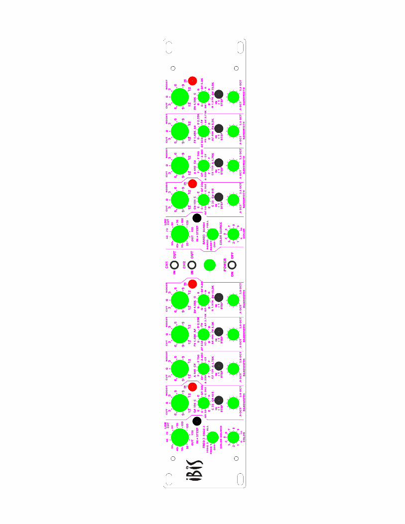
First, each band has 24 frequencies. 12 switch positions and a “+ one step button” thisbutton moves the frequencies up one whole musical step. The high and low bands alsocan be shelving by pushing the shelving button.
The frequency chart showes how each of the bands over lap and how frequencies andmusical notes relate. As an example, with the +1 step button pushed in, the frequencymoves up two positions on the chart. 32.7 Hz which is the lowest frequency will become36.7 Hz
There is a dead zone of about plus and minus .3 db on the “boost / cut” controls where theEQ is flat in response. This allows an easy way to set your bands flat. The range is plusor minus 12 db and is not stepped. The mastering version has a range of 6 db in .5 dbsteps with a 1 db step between 5 and 6.
The Bandwidth is not stepped on the standard version and is steped on the masteringversion. the range is from 0.2 Oct to 4 Oct this is at 12 db of boost
The low cut is 12 db per octave, but the steep button increases the slope to 24 db peroctave.
The filters are of a special type that provide a very clean and smooth sound. To addflexibility to the equalizer a color knob is inculuded.
The color knob is an additive second / third harmonic distortion type of process,it can be applied to the full program or any one of the 4 bands. When doing a “cut” it willsubtract the harmonic content. The Color Knob is not stepped on the standard versionand is stepped on the mastering version
The use of the color function will allow you to change the equalizer from a very transparentsound to a colored sound. Using it on the low frequencies, band 1, it will add warmth. Onband 3 it will add presence and some nice upper midrange detail. On the high frequencyband it will add air.

C
32.7
65.4
131
262
523
1047
2093
4186
8372
1674
4
34.6
69.3
139
277
554
1109
2218
4435
8869
1774
0
36.7
73.4
147
294
587
1175
2349
4699
9397
1879
4
38.9
77.8
155.
6
311
622
1245
2489
4978
9956
1991
2
41.2
82.4
165
330
659
1319
2637
5274
1054
8
2109
6
43.7
87.3
175
349
698
1397
2794
5588
1117
5
740
1480
2960
5920
1183
9
784
1568
3136
6272
1254
4
830
1661
3322
6645
1328
9
880
1760
3520
7040
1408
0
932
1865
3729
7459
1491
7
988
1976
3951
7902
1580
4
C#
DD
#E
FF#
GG
#A
A#
B
46.2
92.5
185
370
49 98 196
392
51.9
104
208
415
55 110
220
440
58.3
116.
6
233
466
61.7
123.
5
247
494
IBIS
FR
EQ
UE
NC
Y C
HA
RT
Ban
d 1
+ 1
ste
p lo
wes
t fre
quen
cy is
36.
7 H
zB
and
2 +
1 s
tep
low
est f
requ
ency
is 1
55 H
zB
and
3 +
1 s
tep
low
est f
requ
ency
is 5
23 H
zB
and
4 +
1 s
tep
low
est f
requ
ency
is 1
760
Hz

BAND 1 EQ CURVES
This graph showes band 1 the low frequency band, The peaking curve is at a bandwidth1.5 octaves and is for reference. The shelving curves are with the shelf button pushed in.Only one frequency is showen for clarity

BAND 4 EQ CURVES
This graph showes band 4 the high frequency band, The peaking curve is at a bandwidth1.5 octaves for reference. The shelving curves are with the shelf button pushed in. Onlyone frequency is showen for clarity

BAND EQ CURVES PEAKING
This graph showes a typical peaking eq curve. This was measured on band 3.Only one frequency is showen for clarity. There are several boost and cut levels at differ-ent bandwidths. These curves apply to all 4 bands for a total of 96 different frequencies.

LOW CUT EQ CURVES
This graph showes a typical low cut curve. Three frequencies are showen for clarity. Eachshowing the 12 db pre octave slope and the 24 db per octave slope. Frequencies of 40 ,80, and 150 Hz are showen.

LOW CUT EQ CURVES
This graph showes the range of the low cut curves. All frequencies are at the 24 db peroctave slope.

IBIS INSERT CONNECTOR
If you are going to use this, use it with caution. The inserts are a loop and must be normaledfor the band to work correctly. If there is a phase inversion in the inserted device it is possiblethat the system will be an oscillator. This will not hurt Ibis, but your Speakers.
boost / cut amp
filter
SendReturnInsert
IBIS INPUT IBIS OUTPUT
There are 4 filter circuits in parallel in Ibis. When using the insert with a compressor you aremodifing the filter output before is sums back into the audio path. The inserts are unbalanced
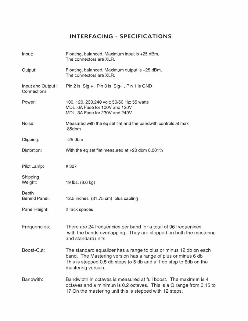
INTERFACING - SPECIFICATIONS
Input: Floating, balanced. Maximum input is +25 dBm.
The connectors are XLR.
Output: Floating, balanced. Maximum output is +25 dBm.
The connectors are XLR.
Input and Output : Pin 2 is Sig + , Pin 3 is Sig- , Pin 1 is GND
Connections
Power: 100, 120, 230,240 volt; 50/60 Hz; 55 watts
MDL .6A Fuse for 100V and 120V
MDL .3A Fuse for 230V and 240V
Noise: Measured with the eq set flat and the bandwith controls at max
-85dbm
Clipping: +25 dbm
Distortion: With the eq set flat measured at +20 dbm 0.001%
Pilot Lamp: # 327
Shipping
Weight: 19 lbs. (8.6 kg)
Depth
Behind Panel: 12.5 inches (31.75 cm) plus cabling
Panel Height: 2 rack spaces
Frequencies: There are 24 frequencies per band for a total of 96 frequenices with the bands overlapping. They are stepped on both the mastering
and standard units
Boost-Cut: The standard equalizer has a range to plus or minus 12 db on eachband. The Mastering version has a range of plus or minus 6 db
This is stepped 0.5 db steps to 5 db and a 1 db step to 6db on the
mastering version.
Bandwith: Bandwidth in octaves is measured at full boost. The maximun is 4octaves and a minimun is 0.2 octaves. This is a Q range from 0.15 to
17 On the mastering unit this is stepped with 12 steps.


