52
SATELLITE COMPASS SC-33 OPERATOR'S MANUAL www.furuno.com Model

SATELLITE COMPASS
SC-33
OPERATOR'S MANUAL
www.furuno.com
Model


i
IMPORTANT NOTICES
General
• This manual has been authored with simplified grammar, to meet the needs of international users.• The operator of this equipment must read and follow the instructions in this manual. Wrong oper-
ation or maintenance can void the warranty or cause injury.• Do not copy any part of this manual without written permission from FURUNO.• If this manual is lost or worn, contact your dealer about replacement.• The contents of this manual and the equipment specifications can change without notice.• The example screens (or illustrations) shown in this manual can be different from the screens you
see on your display. The screens you see depend on your system configuration and equipment settings.
• Save this manual for future reference.• Any modification of the equipment (including software) by persons not authorized by FURUNO will
void the warranty.• The following concern acts as our importer in Europe, as defined in DECISION No 768/2008/EC.
- Name: FURUNO EUROPE B.V.- Address: Ridderhaven 19B, 2984 BT Ridderkerk, The Netherlands
• All brand, product names, trademarks, registered trademarks, and service marks belong to their respective holders.
How to discard this product
Discard this product according to local regulations for the disposal of industrial waste. For disposal in the USA, see the homepage of the Electronics Industries Alliance (http://www.eiae.org/) for the cor-rect method of disposal.
How to discard a used battery
Some FURUNO products have a battery(ies). To see if your product has a battery, see the chapter on Maintenance. If a battery is used, tape the + and - terminals of the battery before disposal to pre-vent fire, heat generation caused by short circuit.
In the European UnionThe crossed-out trash can symbol indicates that all types of batteries must not be discarded in standard trash, or at a trash site. Take the used batteries to a battery collection site according to your national legislation and the Batteries Directive 2006/66/EU.
In the USAThe Mobius loop symbol (three chasing arrows) indicates that Ni-Cd and lead-acid rechargeable batteries must be recycled. Take the used batteries to a battery collection site according to local laws.
In the other countriesThere are no international standards for the battery recycle symbol. The number of symbols can in-crease when the other countries make their own recycle symbols in the future.
Cd
Ni-Cd Pb

ii
SAFETY INSTRUCTIONS
Indicates a potentially hazardous situation which, if not avoided, could result in death or serious injury.
Indicates a potentially hazardous situation which, if not avoided, can result in minor or moderate injury.
Warning, Caution Mandatory Action Prohibitive Action
The operator and installer must read the applicable safety instructions before attempting toinstall or operate the equipment.
WARNINGDo not open the equipment.
Only qualified personnel should workinside the equipment.
Do not disassemble or modify theequipment.
Fire, electrical shock or serious injury canresult..
Safety instructions for the operator
Observe the following compass safedistances to prevent interference to amagnetic compass:
Standardcompass
Steeringcompass
0.45 m 0.40 mSC-33
Turn off the power at the switchboardbefore beginning the installation.
Fire or electrical shock can result if thepower is left on.
Be sure that the power supply iscompatible with the voltage rating of theequipment.
Connecting an incompatible power supplycan cause fire or damage the equipment.The voltage rating appears on the inletof power.
WARNINGSafety instructions for the installer
Warning LabelA warning label is attached to the equipment.Do not remove the label. If the label is missingor illegible, contact a FURUNO agent or dealerabout replacement.
Name: Warning Label(1)Type: 86-003-1011-3Code No.: 100-236-233-10
CAUTION
WARNING
CAUTIONWARNING
To avoid electrical shock, do not remove cover. No user-serviceable parts inside.
Do not use high-pressure cleaners to clean this equipment.
This equipment has the waterproof ratingoutlined in the specifications, at the backof this manual. However, the use of high-pressure cleaning equipment can cause water ingress, resulting in damageto, or failure of, the equipment.
iii
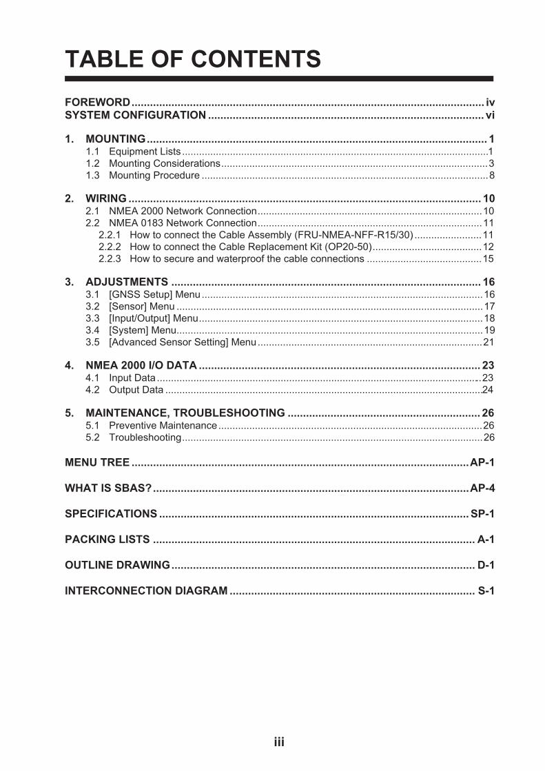
TABLE OF CONTENTS
FOREWORD................................................................................................................... ivSYSTEM CONFIGURATION .......................................................................................... vi
1. MOUNTING............................................................................................................... 11.1 Equipment Lists .............................................................................................................11.2 Mounting Considerations...............................................................................................31.3 Mounting Procedure ......................................................................................................8
2. WIRING ................................................................................................................... 102.1 NMEA 2000 Network Connection................................................................................102.2 NMEA 0183 Network Connection................................................................................11
2.2.1 How to connect the Cable Assembly (FRU-NMEA-NFF-R15/30) ........................112.2.2 How to connect the Cable Replacement Kit (OP20-50).......................................122.2.3 How to secure and waterproof the cable connections .........................................15
3. ADJUSTMENTS ..................................................................................................... 163.1 [GNSS Setup] Menu....................................................................................................163.2 [Sensor] Menu .............................................................................................................173.3 [Input/Output] Menu.....................................................................................................183.4 [System] Menu.............................................................................................................193.5 [Advanced Sensor Setting] Menu................................................................................21
4. NMEA 2000 I/O DATA ............................................................................................ 234.1 Input Data ....................................................................................................................234.2 Output Data .................................................................................................................24
5. MAINTENANCE, TROUBLESHOOTING ............................................................... 265.1 Preventive Maintenance..............................................................................................265.2 Troubleshooting...........................................................................................................26
MENU TREE ..............................................................................................................AP-1
WHAT IS SBAS?.......................................................................................................AP-4
SPECIFICATIONS ..................................................................................................... SP-1
PACKING LISTS ......................................................................................................... A-1
OUTLINE DRAWING................................................................................................... D-1
INTERCONNECTION DIAGRAM ................................................................................ S-1

FOREWORD
A Word to the Owner of the SC-33
Congratulations on your choice of the FURUNO SC-33 SATELLITE COMPASS™. We are confi-dent you will see why the FURUNO name has become synonymous with quality and reliability.
Since 1948, FURUNO Electric Company has enjoyed an enviable reputation for quality marine electronics equipment. This dedication to excellence is furthered by our extensive global network of agents and dealers.
This equipment is designed and constructed to meet the rigorous demands of the marine environment. However, no machine can perform its intended function unless installed properly. Please carefully read and follow the recommended procedures for installation.
Thank you for considering and purchasing FURUNO equipment.
Features
The SC-33 outputs highly accurate heading, GNSS position data and speed and motion data for
AIS, Tracked Target (TT) radar, autopilots, etc. Data is output in NMEA 2000® (NMEA2000 is a trademark of National Marine Electronic Association (the United States)) format, and with connec-tion of the optional interface unit the data can be converted to NMEA 0183 format. Setting time is within three minutes and the follow-up performance is an excellent 45°/s.
• Heading accuracy of 0.4° RMS
• Perfect heading sensor for radar/TT, AIS, scanning sonar, etc.
• Outputs accurate heading, position, time, speed, course.
• Pitch and roll output in digital format for ship's motion correction
• A new SATELLITE COMPASS™ designed with FURUNO advanced GNSS kinematic technol-ogy.
• Data can be output in NMEA 2000 format
• Free from regular maintenance
• Aesthetically pleasing antenna fits nicely on recreational boats
• Outputs acceleration speed and angular velocity at installation
Software used in this product
This equipment uses the following open source software.
This product includes software to be licensed under the GNU General Public License (GPL) ver-sion 2.0, GNU Lesser General Public Software License (LGPL) version 2.0, Apache, BSD and oth-ers. The program(s) is/are free software(s), and you can copy it and/or redistribute it and/or modify it under the terms of the GPL version 2.0 or LGPL version 2.0 as published by the Free Software Foundation. Please access to the following URL if you need source codes.
https://www.furuno.co.jp/en/contact/cnt_oss_e01.html
Program No.
OS : 2051593-01.**
iv

FOREWORD
APL : 2051594-01.**
GNSS: 48505230**
** denotes minor modifications.
v
vi
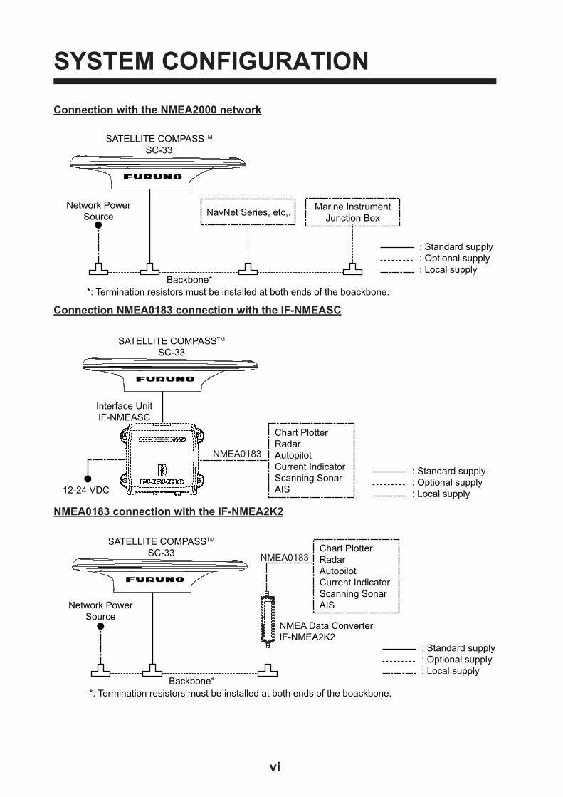
SYSTEM CONFIGURATION
Connection with the NMEA2000 network
Connection NMEA0183 connection with the IF-NMEASC
NMEA0183 connection with the IF-NMEA2K2
: Standard supply: Optional supply: Local supply
NavNet Series, etc,. Marine InstrumentJunction Box
SATELLITE COMPASSTM
SC-33
Network Power Source
Backbone**: Termination resistors must be installed at both ends of the boackbone.
: Standard supply: Optional supply: Local supply
Chart PlotterRadar AutopilotCurrent IndicatorScanning SonarAIS
IF-NMEASC
SATELLITE COMPASSTM
SC-33
Interface UnitIF-NMEASC
12-24 VDC
NMEA0183
: Standard supply: Optional supply: Local supply
SATELLITE COMPASSTM
SC-33
Backbone**: Termination resistors must be installed at both ends of the boackbone.
NMEA Data ConverterIF-NMEA2K2
Chart PlotterRadar AutopilotCurrent IndicatorScanning SonarAIS
NMEA0183
Network Power Source
1. MOUNTING
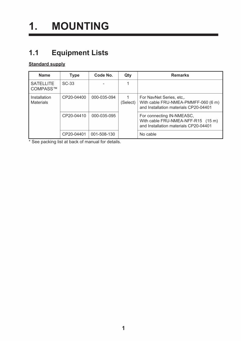
1.1 Equipment Lists
Standard supply
* See packing list at back of manual for details.
Name Type Code No. Qty Remarks
SATELLITE COMPASS™
SC-33 - 1
Installation Materials
CP20-04400 000-035-094 1(Select)
For NavNet Series, etc,. With cable FRU-NMEA-PMMFF-060 (6 m) and Installation materials CP20-04401
CP20-04410 000-035-095 For connecting IN-NMEASC, With cable FRU-NMEA-NFF-R15 (15 m) and Installation materials CP20-04401
CP20-04401 001-508-130 No cable
1

1. MOUNTING
Optional supply
Name Type Code No. Remarks
Interface Unit IF-NMEASC - See OME-72651-x attached to the Interface Unit.
NMEA Data Converter
IF-NMEA2K2 -
Cable Assembly FRU-NMEA-NFF-R15 001-507-080 For IF-NMEASC, 15m, 6.7
FRU-NMEA-NFF-R30 001-507-090 For IF-NMEASC, 30m, 6.7
Cable Conversion kit
OP20-50 001-506-810 Replacement kit for SC-30 (MJ-A10SPF0015-xxxC)
Contents- Waterproof relay box (JPBS 06)- 120 Lead resistance
(03S9939)- FRU-NMEA-PFF-060- Vinyl tape (0.2X19X10000MM Black, 000-172-691-10)- Self-bonding tape (No.15, 000-174-646-10)
Bird-Repellent Fixture
OP20-36 004-380-830 Four pieces
OP20-37 004-380-840 Single
Cable for NMEA2000 (Micro)
FRU-NMEA-PMMFF-010 001-506-820 w/connectors (Light), 1m
FRU-NMEA-PMMFF-020 001-506-830 w/connectors (Light), 2m
FRU-NMEA-PMMFF-060 001-507-000 w/connectors (Light), 6m
FRU-NMEA-PFF-010 001-507-010 w/connector (Light), 1m
FRU-NMEA-PFF-020 001-507-030 w/connector (Light), 2m
FRU-NMEA-PFF-060 001-507-040 w/connector (Light), 6m
Connector for NMEA2000
FRU-MM1MF1MF1001 001-507-050 T-Connector, Micro Style: 3
FRU-MF000000001 001-507-060 Micro Style, female,termination resistor
FRU-MM100000001 001-507-070 Micro Style, male,termination resistor
2

1. MOUNTING
1.2 Mounting ConsiderationsIn addition to the considerations described in this section, keep the length of the SC-33 cable in mind when selecting a mounting location.
General considerations
Mount the SC-33 above radar mast
As shown in the figure below, mount the SC-33 above a radar mast. This provides an unobstruct-ed path between the SC-33 and the satellite, regardless of vessel heading. Follow the procedure on the next page to choose an installation site.
SC-33 mounted above antennas and structures
If SC-33 cannot be installed above radar mast
If absolutely impossible to do otherwise, the SC-33 may be installed below a radar mast. However, certain guidelines must be followed to prevent the shading and multipath problems which occur as shown in the figure below. Follow the procedure on the next page to choose an installation site.
Problems associated with mounting SC-33 below a radar mast
SC-33
Mast
Radar Antenna
Bridge
Radar Antenna
SC-33 Reception blocked by mast.
Location influencedby reflected wave.
3

1. MOUNTING
Selecting the installation site
The installation site must satisfy the four conditions described in this section. After choosing the site, determine installation height, following the procedure in the next section.
CONDITION 1: Locate the SC-33 away from masts that might prevent reception of the GNSS signal
• Install the SC-33 where the field of view against zenith is at least ±85°. The installation site should be as high as possible, above masts, etc. which might interfere with reception.
• If the above condition cannot be satisfied, separate the SC-33 so that the horizontal angle to the interfering object is less than 10°. Refer to the table below to determine minimum separation distance.
CONDITION 2: Locate the SC-33 out of radar beams
• Locate the SC-33 more than 20° above the top of a radar antenna.
• Separate the SC-33 at least 3 m from an open-type radar antenna.
• If the SC-33 cannot be separated at least 3 meter from an open-type radar antenna, install it at least 80 cm above the top of the radar antenna.
Separation distances from radar antenna
Mast diameter Min. separation distance10 cm 1.5 m30 cm 3 m
SC-33
Zenith
+85°-85°
Mast, etc.Mast, etc.
SC-33Less than 10°Less than 10°
Top View
H1
H2
Radar Antenna(open type)
SC series antenna installed away from radar beam
L=More than
3 m
Morethan20°
Positional relationship between radar antenna and SC-33- If H2 is at least 1 m and L is more than 3 m, the elevation angle from the radar should be more than 20°.- If L is less than 3 m, H1 should be more than 0.8 m.
SC-33
Mast, etc.Mast, etc.
4

1. MOUNTING
CONDITION 3: Locate the SC-33 out of Inmarsat
Separate the SC-33 from an Inmarsat Fleet Broadband Antenna by at least 3 m.
Separation distance from Inmarsat Fleet Broadband Antenna
CONDITION 4: Locate the SC-33 away from communication (VHF, etc.) antennas
Separate the SC-33 as far as possible from communication antennas.
CONDITION 5: Select a stable location with minimal or no vibrations from engines or waves
Install the SC-33 in a stable location. The SC-33 contains highly sensitive GNSS and angular speed sensors. Therefore, try to install it where shock, vibration, etc. are minimal.
More than 3 m
SC-33 Satellite Compass Inmarsat Fleet Broadband Antenna
Minimal or no vibrations
Diameter of mounting pipeshall be at least 80 mm.
No vibrations at mounting base
SC-33
Mast, etc.Mast, etc.
5

1. MOUNTING
Installation height
After choosing the installation site, determine the installation height, considering composition of the deck and surrounding area.
The deck is flat and metallic, or the area around the installation site is metallic
• If metallic surface is wider than the area of the top view of the SC-33, install the SC-33 at least 800 mm above the deck.
The deck is non-metallic (FRP, etc.) and there are no metallic objects around the installation site
• If mounting surface is non-metallic and there is no radar or Inmarsat antenna in the vicinity, mount the SC-33 directly on the non-metallic surface. This can be done provided the metallic material support is smaller than the SC-33. If the SC-33 is to be fixed to a mounting pipe, choose a site where there is less vibration.
Metallic surface
SC-33
Separation distanceat least 800 mm
Metallic pipe, etc.
Non-metallic (FRP, etc.) overhead
Metallic material providing support for non-metallic overhead
6

1. MOUNTING
Installation examples for a pleasure boat
No tuna tower
With tuna tower
Sensor fixed toa platform
Do not mount the sensor like this. Vibration can damage the sensor.
Fixing holes should "surround" the sensor. Further, fix the mounting pole at a right angle.The recommended dimensions for the pole are:
Diameter: more than φ80 mmLength: less than 500 mm
Radomeradar antenna
Fixing hole
Fixing hole
Fix directly to vessel, aboveother equipment as much as possible.
Pipe withlarge diameter
Fix sensor to pipe at stern side of sensor if guardrail or the like runs to top of tuna tower, etc.
No pipe
7

1. MOUNTING
1.3 Mounting ProcedureNote 1: The bird-repellent fixtures (optional supply) can be attached to the antenna cover to pre-vent birds from landing on the cover. If it is more convenient to attach the bird-repellent fixtures before securing the antenna unit to the mounting location, do step 6 below before fixing the an-tenna unit.
Note 2: According to the installation location, connecting the antenna pig tale connector to the NMEA2000 bus or a cable from an optional unit in advance is easy to fix to the location. Connect a cable with reference to step 5 beforehand. Then, waterproof the connection.
1. As shown in the figure below, weld a platform (local supply) for which to mount the SC-33. The thickness of the platform should be 5 mm to 15 mm.
2. Orient the antenna unit to face the bow, referring to the figure above. The antenna should be installed within ±2.5° of the bowline.Note 1: Take care not to crush the cabling when mounting the antenna to the platform.
Note 2: Take care not to cover the vent hole on the antenna.
3. Secure the unit to the platform with four sets of M10 hex. nuts, spring washers and flat washers (all included as installation materials) with 20 ±2 N•m torque.
BOW200
300
160 Flat washer
5 mm to 15 mm
Spring washerHexagonal nut (M10)
Fixing hole (ø11 mm)160
Positioning the antenna cable(Stern view)
IndentIndent
CableCable
Rear view
Vent hole
Nut 1Torque 25 N•m Nut 2
Torque 20 N•m Nut 1&2 (Simultaneous work)Nut1: Rotate slightly in opposite direction to 1 .Nut 2: Fixed in place.
Antenna unitPlatform
Flat washer
Spring washer
How to fasten double nuts
8
1. MOUNTING
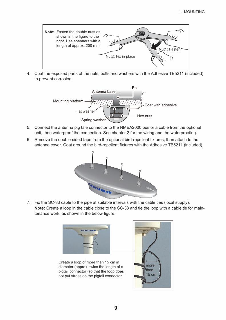
4. Coat the exposed parts of the nuts, bolts and washers with the Adhesive TB5211 (included) to prevent corrosion.
5. Connect the antenna pig tale connector to the NMEA2000 bus or a cable from the optional unit, then waterproof the connection. See chapter 2 for the wiring and the waterproofing.
6. Remove the double-sided tape from the optional bird-repellent fixtures, then attach to the antenna cover. Coat around the bird-repellent fixtures with the Adhesive TB5211 (included).
7. Fix the SC-33 cable to the pipe at suitable intervals with the cable ties (local supply).Note: Create a loop in the cable close to the SC-33 and tie the loop with a cable tie for main-tenance work, as shown in the below figure.
Nut2: Fix in place
Nut1: FastenNut1: Fasten
Note: Fasten the double nuts as shown in the figure to the right. Use spanners with a length of approx. 200 mm.
Note: Fasten the double nuts as shown in the figure to the right. Use spanners with a length of approx. 200 mm.
Mounting platform
Hex nuts
Bolt
Spring washer
Flat washerCoat with adhesive.
Antenna baseAntenna base
Create a loop of more than 15 cm in diameter (approx. twice the length of a pigtail connector) so that the loop does not put stress on the pigtail connector.
more than 15 cm
9

2. WIRING
Attention
• Do not loop the antenna cable.
• Do not bundle the SC-33 cable with radio equipment cables.
• When the above noise reductions are insufficient, adjust the squelch on the radio equipment.
2.1 NMEA 2000 Network ConnectionUsing the supplied cable assembly, connect the SC-33 cable (Micro style connector) to the NMEA2000 network backbone.
The SC-33 connects to the devices in an NMEA 2000 network with a drop cable, which is connected to a backbone cable w/T-type connectors. The backbone cable can be light or heavy type. Attach a terminator at both ends of the backbone cable. Use a Micro-C connector to connect to the devices. We recommended that power from the NMEA 2000 network be input at the center of the backbone cable. For connection to the IF-NMEA SC Interface Unit, see its operator's manual.
What is NMEA 2000 (CAN) bus?
CAN bus is a communication protocol (NMEA2000 compliant) that shares multiple data and signals through a single backbone cable. You can simply connect any CAN bus devices onto the backbone cable to expand your network on-board. With CAN bus, IDs are assigned to all the devices in the network, and the status of each sensor in the network can be detected. All the CAN bus devices can be incorporated into the CAN bus network. For detailed information about CAN bus wiring, see “Furuno CAN bus Network Design Guide” (Type: TIE-00170) on Tech-Net.
Backbone cable
SC-33
FRU-NMEA-PMMF-060 (6 m)
Terminator 1
MultiFunctionDisplay
Terminator 2T-connector T-connector
Power
Pigtail cable (0.8 m)
10

2. WIRING
Guideline for Connecting
Follow these guidelines when selecting a mounting location.
• Where the cable connectors and CAN bus/NMEA2000 connectors are subjected to moisture or water spray, waterproof the connectors as shown below.
1. Wrap the connection point with a single layer of vinyl tape.
2. Wrap one layer of self-bonding tape over the vinyl tape.
3. Wrap two layers of vinyl tape over the self-bonding tape.
2.2 NMEA 0183 Network ConnectionOptional interface unit IF-NMEASC is required when connecting with NMEA0183 equipment. For IF-NMEASC, see the Operator’s Manual of the IF-NMEASC.
2.2.1 How to connect the Cable Assembly (FRU-NMEA-NFF-R15/30)
The installation of the other terminal connector and T-connector is not required because the FRU-NMEA-NFF-R15/30 is the terminal resistance internal cable of 120 ohm.
Securing and waterproofing connections
• Where the cable connectors and CAN bus/NMEA2000 connectors are subjected to moisture or water spray, waterproof the connectors as shown below.
1. Wrap the connection point with a single layer of vinyl tape.
2. Wrap one layer of self-bonding tape over the vinyl tape.
3. Wrap two layers of vinyl tape over the self-bonding tape.
Waterproof the connectors
T-connector
Wrap connection in self-bonding tape for waterproofing.
STEP 2
STEP 1
Wrap the self-bonding tape with vinyl tape, covering approx. 50 mm of the connecting cable. Bind the tape ends with cable cable ties to prevent the tape from unraveling.
11

2. WIRING
2.2.2 How to connect the Cable Replacement Kit (OP20-50)
Use a waterproof relay box (JPBS06) to relay connection when connecting to the SC-33 with the MJ-A10SPF0015-150C/300C cable used in SC-30.
1) Unfasten four washer head screws on the top of the waterproof relay box to remove the cover.
2) Fabricate the MJ-A10SPF0015-150C/300C as follows.
1) Cut the MJ-10 connector part. Expose inner vinyl sheath by approx. 40 mm. Be careful not to damage inner shield and cores.
2) Cut unused wires (green, yellow and purple) to approx. 10 mm, then isolate them with vinyl tape. Wrap the drain wire with a vinyl tube.
Note: Make sure the rubber bush and ring are oriented correctly (as shown in the figure above).
40 mm 40 mm 40 mm
Rubber Bush (Large)+ Ring
Rubber Bush (Large)+ Ring
10 mm10 mm10 mm
Wrap the drain wires with the vinyl tube. Wrap the drain wires with the vinyl tube.
Vinyl tapeVinyl tape
CapCap
12

2. WIRING
3) Fabricate the FRU-NMEA-PFF-060 cable as follows.
1) On the end of the side without the FRU connector, cut into the one end part of the FRU connector. Expose inner vinyl sheath by approx. 40 mm. Be careful not to damage inner shield and cores.
2) Wrap the drain wire with a vinyl tube.
Note: Make sure the rubber bush and ring are oriented correctly (as shown in the figure above).
3) Twist the blue and white core wires and a resistor assembly, and attach a closed-end lug to the wires.
40 mm 40 mm 40 mm
FRU-NM EA-PFF-060FRU-NM EA-PFF-060
Resistor Assembly(120 OHM-1007#24-L50 supplied) Resistor Assembly(120 OHM-1007#24-L50 supplied)
Rubber Bush (Large)+ Ring
Rubber Bush (Large)+ Ring
Rubber Bush (Large)+ Ring
Rubber Bush (Large)+ Ring
Vinyl tapeVinyl tape
CapCap
Twist and fix the closed-end lug to the tip.Twist and fix the closed-end lug to the tip.
Resistor Assembly (120 OHM-1007#24-L50 supplied) Resistor Assembly (120 OHM-1007#24-L50 supplied)
Rubber Bush (Large)+ Ring
Rubber Bush (Large)+ Ring
13

2. WIRING
4) Connect the cables to the waterproof relay box.Connect the CAN cable (FRU-NMEA-PFF-060) included to the cable replacement kit and the cable for SC-30 (MJ-A10SPF0015-150C/300C) to the internal terminal box.
5) Fit the rubber bush, ring and cap, in that order. Make sure the order is as shown in the be-low figure, to keep the IP rating.
6) Fit the cover to the waterproof relay box, then secure the cover with the four washer screws removed at step 1.
FRU-NMEA-PFF-060FRU-NMEA-PFF-060
Waterproof Relay Box (JPBS06)Waterproof Relay Box (JPBS06)
MJ-A10SPF0015-150C/300CMJ-A10SPF0015-150C/300C
Cap
Ring
Rubber bush
Waterproof Relay Box
Cap
14

2. WIRING
2.2.3 How to secure and waterproof the cable connections
Cable connection for the waterproof relay box, whether exposed to weather or otherwise, should be waterproofed and secured after making the connection.
1) Wrap the cap with several layers of self-bonding tape (supplied), to reduce the height differ-ence between the cap and the box.
2) Starting at approximately 40 mm from the both caps, wrap the cap and waterproof relay box with three layers of self-bonding tape.
Note: Take care that the self-bonding tape is not cut on the waterproof relay box or cap edges.
3) Wrap two layers of vinyl tape, in opposite direction, to cover the self-bonding tape.
Cap
Self-Bonding Tape
Self-Bonding Tape
Approx. 40 mmApprox. 40 mm
Vinyl Tape
15
3. ADJUSTMENTS
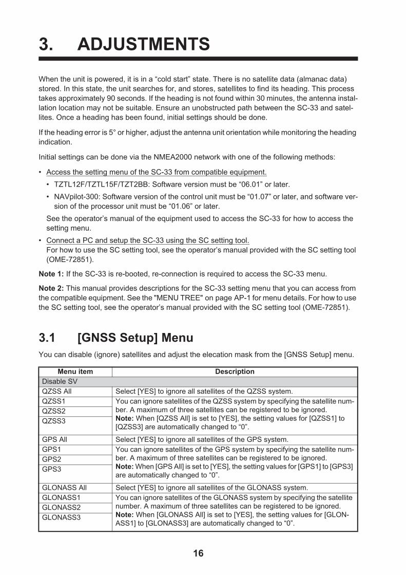
When the unit is powered, it is in a “cold start” state. There is no satellite data (almanac data) stored. In this state, the unit searches for, and stores, satellites to find its heading. This process takes approximately 90 seconds. If the heading is not found within 30 minutes, the antenna instal-lation location may not be suitable. Ensure an unobstructed path between the SC-33 and satel-lites. Once a heading has been found, initial settings should be done.
If the heading error is 5° or higher, adjust the antenna unit orientation while monitoring the heading indication.
Initial settings can be done via the NMEA2000 network with one of the following methods:
• Access the setting menu of the SC-33 from compatible equipment.
• TZTL12F/TZTL15F/TZT2BB: Software version must be “06.01” or later.
• NAVpilot-300: Software version of the control unit must be “01.07” or later, and software ver-sion of the processor unit must be “01.06” or later.
See the operator’s manual of the equipment used to access the SC-33 for how to access the setting menu.
• Connect a PC and setup the SC-33 using the SC setting tool.For how to use the SC setting tool, see the operator’s manual provided with the SC setting tool (OME-72851).
Note 1: If the SC-33 is re-booted, re-connection is required to access the SC-33 menu.
Note 2: This manual provides descriptions for the SC-33 setting menu that you can access from the compatible equipment. See the "MENU TREE" on page AP-1 for menu details. For how to use the SC setting tool, see the operator’s manual provided with the SC setting tool (OME-72851).
3.1 [GNSS Setup] MenuYou can disable (ignore) satellites and adjust the elecation mask from the [GNSS Setup] menu.
Menu item DescriptionDisable SVQZSS All Select [YES] to ignore all satellites of the QZSS system.QZSS1 You can ignore satellites of the QZSS system by specifying the satellite num-
ber. A maximum of three satellites can be registered to be ignored.Note: When [QZSS All] is set to [YES], the setting values for [QZSS1] to [QZSS3] are automatically changed to “0”.
QZSS2QZSS3
GPS All Select [YES] to ignore all satellites of the GPS system.GPS1 You can ignore satellites of the GPS system by specifying the satellite num-
ber. A maximum of three satellites can be registered to be ignored.Note: When [GPS All] is set to [YES], the setting values for [GPS1] to [GPS3] are automatically changed to “0”.
GPS2GPS3
GLONASS All Select [YES] to ignore all satellites of the GLONASS system.GLONASS1 You can ignore satellites of the GLONASS system by specifying the satellite
number. A maximum of three satellites can be registered to be ignored.Note: When [GLONASS All] is set to [YES], the setting values for [GLON-ASS1] to [GLONASS3] are automatically changed to “0”.
GLONASS2GLONASS3
16
3. ADJUSTMENTS
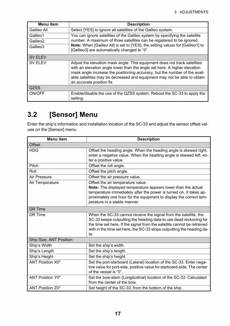
3.2 [Sensor] MenuEnter the ship’s information and installation location of the SC-33 and adjust the sensor offset val-ues on the [Sensor] menu.
Galileo All Select [YES] to ignore all satellites of the Galileo system.Galileo1 You can ignore satellites of the Galileo system by specifying the satellite
number. A maximum of three satellites can be registered to be ignored.Note: When [Galileo All] is set to [YES], the setting values for [Galileo1] to [Galileo3] are automatically changed to “0”.
Galileo2Galileo3
SV ELEVSV ELEV Adjust the elevation mask angle. This equipment does not track satellites
with an elevation angle lower than the angle set here. A higher elevation mask angle increase the positioning accuracy, but the number of the avail-able satellites may be decreased and equipment may not be able to obtain an accurate position fix
QZSSON/OFF Enable/disable the use of the QZSS system. Reboot the SC-33 to apply the
setting.
Menu item DescriptionOffsetHDG Offset the heading angle. When the heading angle is skewed right,
enter a negative value. When the heading angle is skewed left, en-ter a positive value.
Pitch Offset the roll angle.Roll Offset the pitch angle.Air Pressure Offset the air pressure value.Air Temperature Offset the air temperature value.
Note: The displayed temperature appears lower than the actual temperature immediately after the power is turned on. It takes ap-proximately one hour for the equipment to display the correct tem-perature in a stable manner.
DR TimeDR Time When the SC-33 cannot receive the signal from the satellite, the
SC-33 keeps outputting the heading data to use dead reckoning for the time set here. If the signal from the satellite cannot be retrieved with in the time set here, the SC-33 stops outputting the heading da-ta.
Ship Size, ANT PositionShip’s Width Set the ship’s width.Ship’s Length Set the ship’s length.Ship’s Height Set the ship’s height.ANT Position X0* Set the port-starboard (Lateral) location of the SC-33. Enter nega-
tive value for port-side, positive value for starboard-side. The center of the vessel is “0”.
ANT Position Y0* Set the bow-stern (Longitudinal) location of the SC-33. Calculated from the center of the bow.
ANT Position Z0* Set height of the SC-33, from the bottom of the ship.
Menu item Description
17

3. ADJUSTMENTS
*: The reference position for installation location and calculating position of the 3-axis speed is shown in the following figure:
3.3 [Input/Output] MenuYou can enable/disable PGN output from the SC-33 and adjust transmission rate on the [Input/Output] menu.
The following table shows the PGNs that the SC-33 outputs and transmission rate is adjustable. If you want to disable the PGN, set the transmission rate to “0 msec”. The setting range changes according to the PGN. For the setting range of each PGN, see "MENU TREE" on page AP-1.
Note: Normally, keep the default setting. If there is a need to change the transmission rate, only change the rate for necessary PGNs. An excessive number of PGNs with a low transmission rate can cause problems with PGN output and transmission rates.
CALN-SPD-POSN Y1 (Bow)* Set the bow-stern location fro calculating the 3-axis speed. Ship’s speed can be measured a two locations in addition to the antenna position. Enter the backward distance from the reference position (center of the bow) to the position where you want to measure the ship’s speed. Normally, enter the bow position (Y1) and stern posi-tion (Y2).Note: In the default setting, Y1 and Y2 are entered as follows:• Y1: 0 m (bow position)• Y2: 20 m (20 m backward from bow position)Enter the appropriate value according to the ship’s size, to improve the accuracy of the 3-axis speed.
CALN-SPD-POSN Y2 (Stern)*CALN-SPD-POSN Z (Height)*
PGN PGN name065280 Heave126992 System Time 126993 Heartbeat 127250 Vessel Heading 127251 Rate of Turn 127252 Heave127257 Attitude
Menu item Description
- +
YY
Z
Ship’s Length
Ship’s WidthShip’s Length
Ship’s Height
Reference position(0.0)
Reference position(0.0)
18

3. ADJUSTMENTS
3.4 [System] MenuYou can check the system information, perform the diagnostic test and restore the factory default from the [System] menu.
127258 Magnetic Variation129025 Position, Rapid Update129026 COG and SOG, Rapid Update129029 GNSS Position Data129033 Time and Date129539 GNSS DOPs129540 GNSS Sats in View130310 Environmental Parameters130312 Temperature130314 Actual Pressure130316 Temperature, Extended Range130577 Direction Data130578 Vessel Speed Components130820 Motion Sensor Status130826 Multi Sats In View130842 Six Degrees of Freedom Movement130843 Heel Angle and Roll Information130845 Multi Sats In View Extended130846 Motion Sensor Status Extended
Menu item DescriptionSystem InformationMain PCB Version of the Main board.Sub IMU PCB Version of the SUB IMU board. When the SUB IMU board is not
installed, “- -” appears.MAIN CPU OS Version OS version.MAIN CPU Application Version SC-33 software version.WMM Software version of the WMM (World Magnetic Model).GNSS1 Version of the GNSS core 1 to 3.GNSS2GNSS3CAN Unique Number CAN unique ID of the SC-33.Main Overall Powered Time Total operation time of the Main board.Sub IMU Runtime Total operation time of the SUB IMU board. When the SUB IMU
board is not installed, “- -” appears.Antenna1 Powered Time Total operating time of the antenna 1 and 2.Antenna2 Powered TimeModel Product model name (SC-33).Simple Diagnostic TestSimple Diagnostic Select [START] to perform the diagnostic test.ROM ROM test result (OK or NG).Internal RAM Internal RAM test result (OK or NG)
PGN PGN name
19

3. ADJUSTMENTS
GNSS1 ROM ROM and RAM check results for GNSS1 to 3 (OK or NG).GNSS1 RAMGNSS2 ROMGNSS2 RAMGNSS3 ROMGNSS3 RAMCAN CAN check result (OK or NG).Main Accelerometer Status X Test result for the acceleration sensor on the MAIN board (OK or
NG). X-axis, Y-axis and Z-axis test results are shown. When the SUB IMU board is installed, check result indicates “”- -”.
Main Accelerometer Status YMain Accelerometer Status ZMain Rate Gyro Status X Test result for the gyro sensor on the MAIN board (OK or NG). X-
axis, Y-axis and Z-axis test results are shown. When the SUB IMU board is installed, check result indicates “”- -”.
Main Rate Gyro Status YMain Rate Gyro Status ZMain Magnetic Sensor Status Test result for the magnetic sensor on the MAIN board (OK or
NG). When the SUB IMU board is installed, check result indicates “”- -”.
Main Pressure Sensor Status Test result for the air pressure sensor on the MAIN board (OK or NG). When the SUB IMU board is installed, check result indicates “”- -”.
Sub IMU Accelerometer Status X Test result for the acceleration sensor on the SUB IMU board (OK or NG). X-axis, Y-axis and Z-axis test results are shown. When the SUB IMU board is not installed, check result indicates “”- -”.
Sub IMU Accelerometer Status YSub IMU Accelerometer Status Z
Sub IMU Rate Gyro Status X Test result for the gyro sensor on the SUB IMU board (OK or NG). X-axis, Y-axis and Z-axis test results are shown. When the SUB IMU board is not installed, check result indicates “”- -”.
Sub IMU Rate Gyro Status YSub IMU Rate Gyro Status ZSub IMU Magnetic Sensor Status Test result for the magnetic sensor on the SUB IMU board (OK
or NG). When the SUB IMU board is not installed, check result indicates “”- -”.
Sub IMU Pressure Sensor Status Test result for the air pressure sensor on the SUB IMU board (OK or NG). When the SUB IMU board is not installed, check result indicates “”- -”.
Antenna1 Test Antenna1 and 2 test result.Antenna2 TestReset SettingGNSS Select [YES] to restore the factory default settings for the [GNSS
Setup] menu. Reboot the SC-33 to apply the setting.Menu Settings Select [YES] to restore the factory default settings for the follow-
ing menus:• [GNSS Setup] menu• [DR Time] menu• [Offline] menuReboot the SC-33 to apply the setting.
Factory Reset Select [YES] to restore the factory default settings for all menus excludes the following menus.• [Offset] menu• [Ship Size, ANT Position] menuReboot the SC-33 to apply the setting.
PerformanceCPU Show the CPU usage.Memory Show the memory usage.
Menu item Description
20

3. ADJUSTMENTS
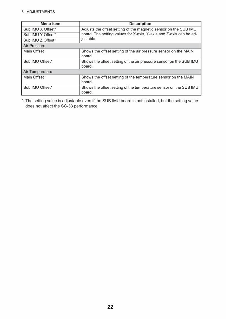
3.5 [Advanced Sensor Setting] MenuYou can check and adjust the gain and offset setting of the sensor on the MAIN and SUB IMU boards from the [Advanced Sensor Setting] menu. The gain and offset settings for the sensor on the MAIN board cannot be adjusted.
OfflineOffline This menu item is prepared for the service person. Normally,
keep the default setting ([OFF]).
Menu item DescriptionRate GyroMain X Percent Shows the gain setting of the gyro sensor on the MAIN board. The
setting values for X-axis, Y-axis and Z-axis are shown.Main Y PercentMain Z PercentMain X Offset Shows the offset setting of the gyro sensor on the MAIN board. The
setting values for X-axis, Y-axis and Z-axis are shown.Main Y OffsetMain Z OffsetSub IMU X Percent* Adjusts the gain setting of the gyro sensor on the SUB IMU board.
The setting values for X-axis, Y-axis and Z-axis can be adjustable.Sub IMU Y Percent*Sub IMU Z Percent*Sub IMU X Offset* Adjusts the offset setting of the gyro sensor on the SUB IMU board.
The setting values for X-axis, Y-axis and Z-axis can be adjustable.Sub IMU Y Offset*Sub IMU Z Offset*AccelerometerMain X Percent Shows the gain setting of the acceleration sensor on the MAIN
board. The setting values for X-axis, Y-axis and Z-axis are shown.Main Y PercentMain Z PercentMain X Offset Shows the offset setting of the acceleration sensor on the MAIN
board. The setting values for X-axis, Y-axis and Z-axis are shown.Main Y OffsetMain Z OffsetSub IMU X Percent* Adjusts the gain setting of the acceleration sensor on the SUB IMU
board. The setting values for X-axis, Y-axis and Z-axis can be ad-justable.
Sub IMU Y Percent*Sub IMU Z Percent*Sub IMU X Offset* Adjusts the offset setting of the acceleration sensor on the SUB IMU
board. The setting values for X-axis, Y-axis and Z-axis can be ad-justable.
Sub IMU Y Offset*Sub IMU Z Offset*MagneticMain X Percent Shows the gain setting of the magnetic sensor on the MAIN board.
The setting values for X-axis, Y-axis and Z-axis are shown.Main Y PercentMain Z PercentMain X Offset Shows the offset setting of the magnetic sensor on the MAIN board.
The setting values for X-axis, Y-axis and Z-axis are shown.Main Y OffsetMain Z OffsetSub IMU X Percent* Adjusts the gain setting of the magnetic sensor on the SUB IMU
board. The setting values for X-axis, Y-axis and Z-axis can be ad-justable.
Sub IMU Y Percent*Sub IMU Z Percent*
Menu item Description
21
3. ADJUSTMENTS
*: The setting value is adjustable even if the SUB IMU board is not installed, but the setting value does not affect the SC-33 performance.
Sub IMU X Offset* Adjusts the offset setting of the magnetic sensor on the SUB IMU board. The setting values for X-axis, Y-axis and Z-axis can be ad-justable.
Sub IMU Y Offset*Sub IMU Z Offset*Air PressureMain Offset Shows the offset setting of the air pressure sensor on the MAIN
board. Sub IMU Offset* Shows the offset setting of the air pressure sensor on the SUB IMU
board. Air TemperatureMain Offset Shows the offset setting of the temperature sensor on the MAIN
board. Sub IMU Offset* Shows the offset setting of the temperature sensor on the SUB IMU
board.
Menu item Description
22
4. NMEA 2000 I/O DATA
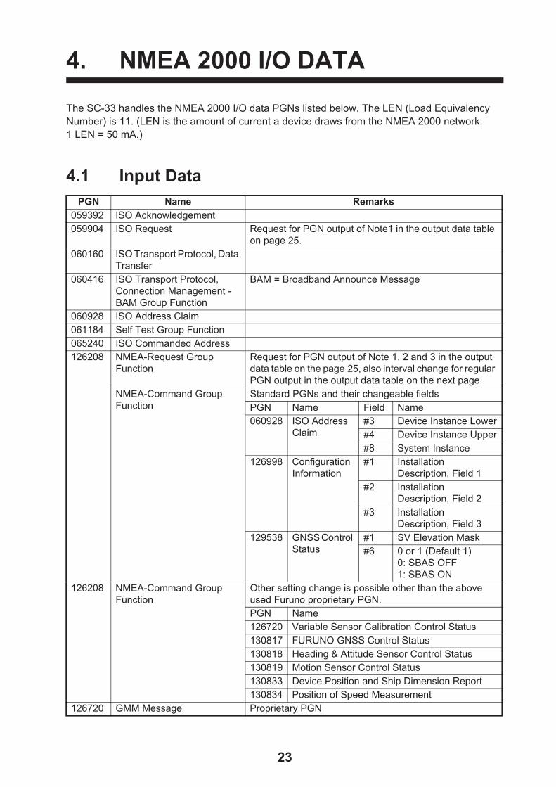
The SC-33 handles the NMEA 2000 I/O data PGNs listed below. The LEN (Load Equivalency Number) is 11. (LEN is the amount of current a device draws from the NMEA 2000 network.1 LEN = 50 mA.)
4.1 Input DataPGN Name Remarks
059392 ISO Acknowledgement059904 ISO Request Request for PGN output of Note1 in the output data table
on page 25. 060160 ISO Transport Protocol, Data
Transfer060416 ISO Transport Protocol,
Connection Management - BAM Group Function
BAM = Broadband Announce Message
060928 ISO Address Claim061184 Self Test Group Function065240 ISO Commanded Address126208 NMEA-Request Group
FunctionRequest for PGN output of Note 1, 2 and 3 in the output data table on the page 25, also interval change for regular PGN output in the output data table on the next page.
NMEA-Command Group Function
Standard PGNs and their changeable fieldsPGN Name Field Name060928 ISO Address
Claim#3 Device Instance Lower#4 Device Instance Upper#8 System Instance
126998 Configuration Information
#1 Installation Description, Field 1
#2 Installation Description, Field 2
#3 Installation Description, Field 3
129538 GNSS Control Status
#1 SV Elevation Mask#6 0 or 1 (Default 1)
0: SBAS OFF1: SBAS ON
126208 NMEA-Command Group Function
Other setting change is possible other than the above used Furuno proprietary PGN. PGN Name126720 Variable Sensor Calibration Control Status130817 FURUNO GNSS Control Status130818 Heading & Attitude Sensor Control Status130819 Motion Sensor Control Status130833 Device Position and Ship Dimension Report130834 Position of Speed Measurement
126720 GMM Message Proprietary PGN
23

4. NMEA 2000 I/O DATA
4.2 Output DataPGN Name Remarks
059392 ISO Acknowledgement - Output for rejection of output request by ISO Request.
060928 ISO Address Claim Note 1, 2 - Transmission at the time of address generation. - Output for receiving the out-put request by ISO Request.
061184 Self Test Group Function - - Proprietary PGN- Output for receiving the Self Test Group Function
065280 Heave 100 ms - Proprietary PGN126208 NMEA-Acknowledge Group Function -126464 PGN List - Transmit PGN’s Group
FunctionNote 1, 2
PGN List - Received PGN’s Group Function Note 1, 2126720 GMM Message - - Proprietary PGN
- Output for GMM Message received.
Variable Sensor Calibration Control Status Note 2 - Proprietary PGN126992 System Time 1000 ms126993 Heart Beat 60000 ms126996 Product Information Note 1, 2126998 Configuration Information Note 1, 2127250 Vessel Heading 100 ms127251 Rate of Turn 100 ms127252 Heave 100 ms127257 Attitude 100 ms 127258 Magnetic Variation 100 ms129025 Position, Rapid Update 100 ms129026 COG & SOG Rapid Update 250 ms129029 GNSS Position Data 1000 ms129033 Time & Date Note 1, 2, 3129538 GNSS Control Status Note 1, 2129539 GNSS DOPs 1000 ms129540 GNSS Sats in View 1000 ms129547 GNSS Pseudo Range Error Statistics Note 1, 2130310 Environmental Parameters
- DEPRECATED500 ms
130312 Temperature - DEPRECATED 2000 ms130314 Actual Pressure 2000 ms130316 Temperature, Extended Range 2000 ms130577 Direction Data 1000 ms130578 Vessel Speed Components 250 ms130816 Self Test Report - - Proprietary PGN
- Output for Self Test Group Function received.
130817 Furuno GNSS Control Status Note 2 - Proprietary PGN130818 Heading & Attitude Sensor Control Status Note 2 - Proprietary PGN130819 Motion Sensor Control Status Note 2 - Proprietary PGN130820 Motion Sensor Status 1000 ms - Proprietary PGN
24
4. NMEA 2000 I/O DATA
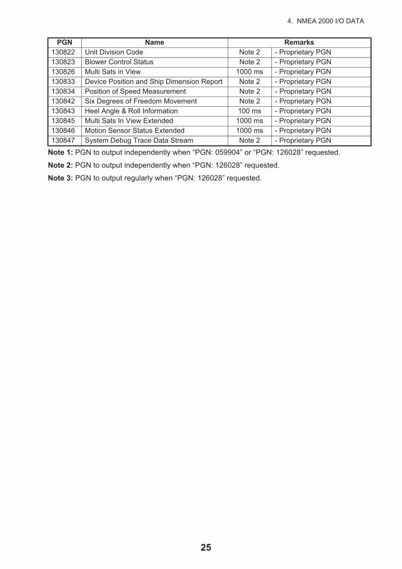
Note 1: PGN to output independently when “PGN: 059904” or “PGN: 126028” requested.
Note 2: PGN to output independently when “PGN: 126028” requested.
Note 3: PGN to output regularly when “PGN: 126028” requested.
130822 Unit Division Code Note 2 - Proprietary PGN130823 Blower Control Status Note 2 - Proprietary PGN130826 Multi Sats in View 1000 ms - Proprietary PGN130833 Device Position and Ship Dimension Report Note 2 - Proprietary PGN130834 Position of Speed Measurement Note 2 - Proprietary PGN130842 Six Degrees of Freedom Movement Note 2 - Proprietary PGN130843 Heel Angle & Roll Information 100 ms - Proprietary PGN130845 Multi Sats In View Extended 1000 ms - Proprietary PGN130846 Motion Sensor Status Extended 1000 ms - Proprietary PGN130847 System Debug Trace Data Stream Note 2 - Proprietary PGN
PGN Name Remarks
25

5. MAINTENANCE, TROUBLE-SHOOTING
This chapter provides the information for keeping your unit in good working order.
5.1 Preventive MaintenanceRegular maintenance is important for good performance. Following the procedures in the table below will help maintain performance.
Preventive maintenance
5.2 TroubleshootingThis section provides basic troubleshooting which the user may follow to restore normal operation. If the problem is not rectified, contact your dealer for advice.
Item Check point Remedy
Connector Check that connector is firmly fastened. Reconnect cable if it has loosened.
Cabling Visually check cabling for signs of wear and damage.
Replace damaged cables.
Cover Cleanliness of cover Dust can be removed with a soft cloth. Do not use chemical based cleaners to clean the cover, as they can remove paint and markings and deform the cover.
Do not apply paint, anti-corrosivesealant or contact spray to coatingor plastic parts of the equipment.
Those items contain organic solventsthat can damage coating and plasticparts, especially plastic connectors.
NOTICE
26

5. MAINTENANCE, TROUBLESHOOTING
Symptom Possible cause and remedyHeading is not output. Check installation site;
• Check for interfering objects near the antenna.• Check the installation site and mounting base for vibration.• Check for antenna of radar, radio equipment, etc. near the instal-
lation site.Check connections;1) NMEA 2000 bus connection
• Check that the connector on the SC-33 is tightly connected.• Check that no stress is applied to the cable and that a loop has
been made with the cable to prevent cable stress.• Check that terminators (120 ohm) are attached at each end of
the NMEA 2000 network.• Check that the input voltage to the SC-33 is between 9 to 32
VDC.• Check that all devices connected to the NMEA 2000 bus are
within the current capacity of the bus.• Check that the cable (FRU-NMEA-PMMF-060 (6m)) is used.
(If power is fed through a trunk line, the feeder cable shall be no longer than 6 m).
• If power to the SC-33 is fed directly from the ship's mains, check breaker switch on mains switchboard and fuse in power cable.
2) IF-NMEASC interface unit connection:See the IF-NMEASC's operator's manual.
Heading output stops often. Position and GNSS-related items are output but heading is not
• Check for obstructions near the SC-33.• Check installation site for vibrations.• Check if other antennas (radar, radio, etc.) are near the installa-
tion site.Equipment in NMEA 2000 network malfunctions when SC-33 is connected.
• Check that terminators (120 ohm) are attached at each end of the NMEA 2000 network.
• Check that the input voltage to the SC-33 is between 9 to 32 VDC.• Check that all devices connected to the NMEA 2000 bus are with-
in the current capacity of the bus.• Check that the cable (FRU-NMEA-PMMF-060 (6m)) is used. (If
power is fed through a trunk line, the feeder cable shall be no lon-ger than 6 m).
Heading is output normally in fine weather but is not output in bad weather.
• Check the installation site for vibrations.
Autopilot jerks suddenly. • Check for obstructions near the SC-33.• Check the installation site and mounting base for vibrations.• Check if other antennas (radar, radio, etc.) are near the installa-
tion site.• Check operation at the autopilot:
1) Check that the rudder angle can be confirmed when heading output has stopped. Check that the necessary alarms are out-put. Confirm that the rudder returns to 0° and the set rudder angle is maintained.
2) Confirm that rudder does not jerk violently when heading out-put is resumed. For example, check that the setting for rudder angle limit is suitable.
27
APPENDIX 1 MENU TREE
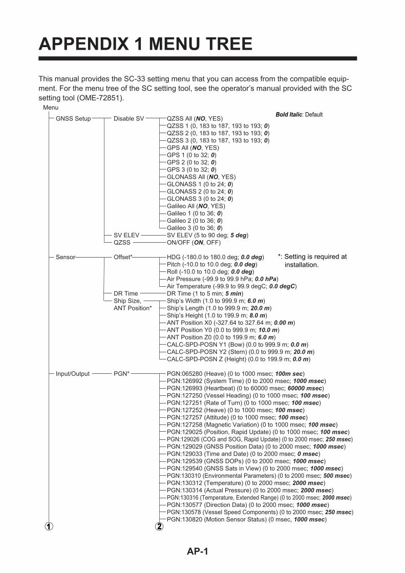
This manual provides the SC-33 setting menu that you can access from the compatible equip-ment. For the menu tree of the SC setting tool, see the operator’s manual provided with the SC setting tool (OME-72851).
GNSS Setup Disable SV QZSS All (NO, YES) QZSS 1 (0, 183 to 187, 193 to 193; 0) QZSS 2 (0, 183 to 187, 193 to 193; 0) QZSS 3 (0, 183 to 187, 193 to 193; 0) GPS All (NO, YES) GPS 1 (0 to 32; 0) GPS 2 (0 to 32; 0) GPS 3 (0 to 32; 0) GLONASS All (NO, YES) GLONASS 1 (0 to 24; 0) GLONASS 2 (0 to 24; 0) GLONASS 3 (0 to 24; 0) Galileo All (NO, YES) Galileo 1 (0 to 36; 0) Galileo 2 (0 to 36; 0) Galileo 3 (0 to 36; 0) SV ELEV SV ELEV (5 to 90 deg; 5 deg) QZSS ON/OFF (ON, OFF)
Sensor Offset* HDG (-180.0 to 180.0 deg; 0.0 deg) Pitch (-10.0 to 10.0 deg; 0.0 deg) Roll (-10.0 to 10.0 deg; 0.0 deg) Air Pressure (-99.9 to 99.9 hPa; 0.0 hPa) Air Temperature (-99.9 to 99.9 degC; 0.0 degC) DR Time DR Time (1 to 5 min; 5 min) Ship Size, Ship’s Width (1.0 to 999.9 m; 6.0 m) ANT Position* Ship’s Length (1.0 to 999.9 m; 20.0 m) Ship’s Height (1.0 to 199.9 m; 8.0 m) ANT Position X0 (-327.64 to 327.64 m; 0.00 m) ANT Position Y0 (0.0 to 999.9 m; 10.0 m) ANT Position Z0 (0.0 to 199.9 m; 6.0 m) CALC-SPD-POSN Y1 (Bow) (0.0 to 999.9 m; 0.0 m) CALC-SPD-POSN Y2 (Stern) (0.0 to 999.9 m; 20.0 m) CALC-SPD-POSN Z (Height) (0.0 to 199.9 m; 0.0 m)
Input/Output PGN* PGN:065280 (Heave) (0 to 1000 msec; 100m sec) PGN:126992 (System Time) (0 to 2000 msec; 1000 msec) PGN:126993 (Heartbeat) (0 to 60000 msec; 60000 msec) PGN:127250 (Vessel Heading) (0 to 1000 msec; 100 msec) PGN:127251 (Rate of Turn) (0 to 1000 msec; 100 msec) PGN:127252 (Heave) (0 to 1000 msec; 100 msec) PGN:127257 (Attitude) (0 to 1000 msec; 100 msec) PGN:127258 (Magnetic Variation) (0 to 1000 msec; 100 msec) PGN:129025 (Position, Rapid Update) (0 to 1000 msec; 100 msec) PGN:129026 (COG and SOG, Rapid Update) (0 to 2000 msec; 250 msec) PGN:129029 (GNSS Position Data) (0 to 2000 msec; 1000 msec) PGN:129033 (Time and Date) (0 to 2000 msec; 0 msec) PGN:129539 (GNSS DOPs) (0 to 2000 msec; 1000 msec) PGN:129540 (GNSS Sats in View) (0 to 2000 msec; 1000 msec) PGN:130310 (Environmental Parameters) (0 to 2000 msec; 500 msec) PGN:130312 (Temperature) (0 to 2000 msec; 2000 msec) PGN:130314 (Actual Pressure) (0 to 2000 msec; 2000 msec) PGN:130316 (Temperature, Extended Range) (0 to 2000 msec; 2000 msec) PGN:130577 (Direction Data) (0 to 2000 msec; 1000 msec) PGN:130578 (Vessel Speed Components) (0 to 2000 msec; 250 msec) PGN:130820 (Motion Sensor Status) (0 msec, 1000 msec)
MenuBold Italic: Default
*: Setting is required at installation.
AP-1

APPENDIX 1 MENU TREE
PGN:130826 (Multi Sats In View) (0 to 2000 msec; 1000msec) PGN:130842 (Six Degrees of Freedom Movement) (0 to 1000 msec; 0 msec) PGN:130843 (Heel Angle and Roll Information) (0 to 1000 msec; 100 msec) PGN:130845 (Multi Sats In View Extended) (0 to 2000 msec; 1000 msec) PGN:130846 (Motion Sensor Status Extended) (0 to 2000 msec; 1000 msec)
System System Main PCB*1
Information Sub IMU PCB*1
MAIN CPU OS Version*1
MAIN CPU Application Version*1
WMM*1
GNSS1*1
GNSS2*1
GNSS3*1
CAN Unique Number*1
Main Overall Powered Time*1
Sub IMU Runtime*1
Antenna1 Powered Time*1
Antenna2 Powered Time*1
Model*1 Simple Start Diagnostic (START) Diagnostic Test ROM*2
Internal RAM*2
GNSS1 ROM*2
GNSS1 RAM*2
GNSS2 ROM*2
GNSS2 RAM*2
GNSS3 ROM*2
GNSS3 RAM*2
CAN*2
Main Accelerometer Status X*2
Main Accelerometer Status Y*2
Main Accelerometer Status Z*2
Main Rate Gyro Status X*2
Main Rate Gyro Status Y*2
Main Rate Gyro Status Z*2
Main Magnetic Sensor Status*2
Main Pressure Sensor Status*2
Sub IMU Accelerometer Status X*2
Sub IMU Accelerometer Status Y*2
Sub IMU Accelerometer Status Z*2
Sub IMU Rate Gyro Status X*2
Sub IMU Rate Gyro Status Y*2
Sub IMU Rate Gyro Status Z*2
Sub IMU Magnetic Sensor Status*2
Sub IMU Pressure Sensor Status*2
Antenna1 Test*2
Antenna2 Test*2
Reset Setting GNSS (NO, YES) Menu Settings (NO, YES) Factory Reset (NO, YES) Performance CPU Memory Offline Offline (OFF, ON)
Advanced Sensor Rate Gyro Main X Percent*1
Setting Main Y Percent*1
Main Z Percent*1
Main X Offset*1
Main Y Offset*1
Main Z Offset*1
*1: Display only.*2: Test result is shown.
AP-2

APPENDIX 1 MENU TREE
Sub IMU X Percent (-8.0 to 8.0 %; 0.0 %) Sub IMU Y Percent (-8.0 to 8.0 %; 0.0 %) Sub IMU Z Percent (-8.0 to 8.0 %; 0.0 %) Sub IMU X Offset (-1999 to 1999; 0) Sub IMU Y Offset (-1999 to 1999; 0) Sub IMU Z Offset (-1999 to 1999; 0) Accelerometer Main X Percent*1
Main Y Percent*1
Main Z Percent*1
Main X Offset*1
Main Y Offset*1
Main Z Offset*1
Sub IMU X Percent (-9.9 to 9.9 %; 0.0 %) Sub IMU Y Percent (-9.9 to 9.9 %; 0.0 %) Sub IMU Z Percent (-9.9 to 9.9 %; 0.0 %) Sub IMU X Offset (-1999 to 1999; 0)
Sub IMU Y Offset (-1999 to 1999; 0) Sub IMU Z Offset (-1999 to 1999; 0) Magnetic Main X Percent*1
Main Y Percent*1
Main Z Percent*1
Main X Offset*1
Main Y Offset*1
Main Z Offset*1
Sub IMU X Percent (-29.0 to 29.0 %; 1.0 %) Sub IMU Y Percent (-29.0 to 29.0 %; 1.0 %) Sub IMU Z Percent (-29.0 to 29.0 %; 0.0 %) Sub IMU X Offset (-1999 to 1999; 0)
Sub IMU Y Offset (-1999 to 1999; 0) Sub IMU Z Offset (-1999 to 1999; 0) Air Pressure Main Offset*1
Sub IMU Offset (-99.9 to 99.9 hPa; 0.0 hPa) Air Temperature Main Offset*1
Sub IMU Offset (-99.9 to 99.9 degC; -12.0 degC)
*1: Display only.
AP-3

APPENDIX 2 WHAT IS SBAS?
A satellite based augmentation system, or SBAS (Satellite Based Augmentation System), is an augmentation system that uses additional messages from satellite broadcasts to support regional and wide area augmentation. SBAS provides GPS signal corrections to SBAS users, for even bet-ter position accuracy, through the GPS error corrections that are widely broadcasted from the geo-stationary satellite.
SBAS is used in America, Europe, Japan and India.
• America: WAAS (Wide Area Augmentation System)
• Europe: EGNOS (Euro Geostationary Navigation Overlay Service)
• Japan: MSAS (Multi-Functional Satellite Augmentation System)
• India: GAGAN (GPS And GEO Augmented Navigation)
These four systems have interoperability. The illustration below shows the coverage area for each provider. This manual uses "SBAS" for these four providers generically.
As of March 6th, 2014
Provider Satellite type Longitude Satellite No.WAAS Intelsat Galaxy XV 133°W 135
TeleSat Anik F1R 107.3°W 138Inmarsat-4-F3 98°W 133
EGNOS Inmarsat-3-F2/AOR-E 15.5°W 120Artemis 21.5°E 124Inmarsat-4-F2 25°E 126SES-5 5°E 136
MSAS MTSAT-1R 140°E 129MTSAT-2 145°E 137
GAGAN GSAT-8 55°E 127GSAT-10 83°E 128
WAAS
MSAS
EGNOS
GAGAN
AP-4
FURUNO SC-33
SP - 1 E7285S01G 200207
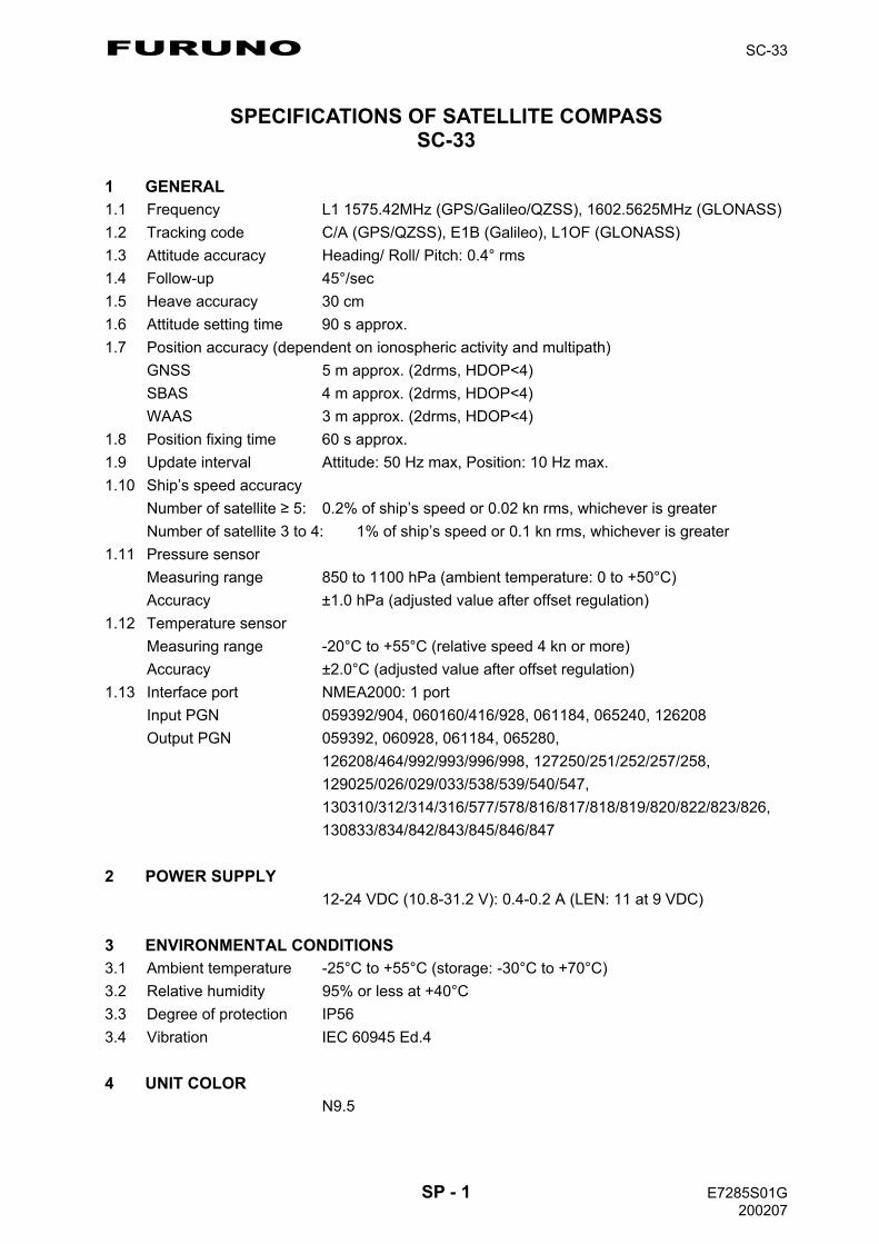
SPECIFICATIONS OF SATELLITE COMPASS SC-33
1 GENERAL 1.1 Frequency L1 1575.42MHz (GPS/Galileo/QZSS), 1602.5625MHz (GLONASS)
1.2 Tracking code C/A (GPS/QZSS), E1B (Galileo), L1OF (GLONASS)
1.3 Attitude accuracy Heading/ Roll/ Pitch: 0.4° rms
1.4 Follow-up 45°/sec
1.5 Heave accuracy 30 cm
1.6 Attitude setting time 90 s approx.
1.7 Position accuracy (dependent on ionospheric activity and multipath)
GNSS 5 m approx. (2drms, HDOP<4)
SBAS 4 m approx. (2drms, HDOP<4)
WAAS 3 m approx. (2drms, HDOP<4)
1.8 Position fixing time 60 s approx.
1.9 Update interval Attitude: 50 Hz max, Position: 10 Hz max.
1.10 Ship’s speed accuracy
Number of satellite 5: 0.2% of ship’s speed or 0.02 kn rms, whichever is greater
Number of satellite 3 to 4: 1% of ship’s speed or 0.1 kn rms, whichever is greater
1.11 Pressure sensor
Measuring range 850 to 1100 hPa (ambient temperature: 0 to +50°C)
Accuracy ±1.0 hPa (adjusted value after offset regulation)
1.12 Temperature sensor
Measuring range -20°C to +55°C (relative speed 4 kn or more)
Accuracy ±2.0°C (adjusted value after offset regulation)
1.13 Interface port NMEA2000: 1 port
Input PGN 059392/904, 060160/416/928, 061184, 065240, 126208
Output PGN 059392, 060928, 061184, 065280,
126208/464/992/993/996/998, 127250/251/252/257/258,
129025/026/029/033/538/539/540/547,
130310/312/314/316/577/578/816/817/818/819/820/822/823/826,
130833/834/842/843/845/846/847
2 POWER SUPPLY 12-24 VDC (10.8-31.2 V): 0.4-0.2 A (LEN: 11 at 9 VDC)
3 ENVIRONMENTAL CONDITIONS 3.1 Ambient temperature -25°C to +55°C (storage: -30°C to +70°C)
3.2 Relative humidity 95% or less at +40°C
3.3 Degree of protection IP56
3.4 Vibration IEC 60945 Ed.4
4 UNIT COLOR N9.5

A-1
A-2

C7285Z03D
A-3
A-4

A-5

D-1
24/J
an/2
018
H.M
AK
I

24
3
A
1
B C
1 2 3 4 5 6 7 8
J7
NET_S
NET_C
NET_H
NET_L
SG
RD
SD
FG
1 2 3 4
J3
5FG
AD-10
1 2
J4 TD-A
TD-B
FG
3
NMEA
1 2TD-A
TD-B
FG
3
NMEA
J5
IF-NMEASC
イン
ター
フェ
イス
ユニット
INTERFACE UNIT
*2
1 2
J2
3 4
VBUS
DM
DP
SG
USB
1 2
TB1
(+)
(-)
20P8195
1 2 3 4
ANALOG
J8 ROLL
SG
PITCH
FG
保守用
FOR MAINTENANCE
*1
DPYC-1.5
SONAR, ETC.
ソナ
ー他
CH-250/270
航法
装置
航法
装置
NAV EQUIPMENT
NAV EQUIPMENT
(IEC61162-1)
(IEC61162-1)
12-24VDC
RADAR/CURRENT IND., ETC.
レーダ
ー/潮
流計
DRAWN
CHECKED
APPROVED
DWG.No.
TITLE
NAME
名 称
INTERCONNECTION DIAGRAM
相互結線
図
REF.No.
SCALE
MASS
kg
サテライトコン
パス
SATELLITE COMPASS
IV-2sq.*1
TD1-A
TD1-B
TD2-A
TD2-B
TD1:DAT
TD2:SFT
SC-33
FRU-NMEA-NFF-R15/30,15/30m,φ6.7
TTYCSLA-1Q*1
TTYCSLA-1Q*1
TTYCSLA-1Q*1
TTYCSLA-1Q*1
20-041-5001-0
NOTE
*1: SHIPYARD SUPPLY.
*2: OPTION.
注記
*2)
オプ
ション
。
*1)
造船
所手配
。
*3)
終端
抵抗内
蔵。
*3: TERMINATOR INSERTED.
*3
アカ
クロ
シロ
アオ
RED
BLK
WHT
BLU
1 2 3 4 5
NET_S
NET_C
NET_H
NET_L
SHIELD
5
SC-33
サテ
ライ
トコ
ンパ
スSATELLITE COMPASS
0.8m
MJ-A10SPF0015-150C/300C
アカ
クロ
シロ
アオ
RED
BLK
WHT
BLU
1 2 3 4 5
アカ
クロ
シロ
アオ
RED
BLK
WHT
BLU
FRU-NMEA-PFF-060,6m
*2
RELAY BOX
WATERPROOF
120 ohm
防水中
継ボ
ック
ス
ケーブル変換キ
ット
OP20-50
CABLE ADAPTER
JPBS 06
15/30m(SC-30用ケーブル)(CABLE FOR SC-30)
REPLACEMENT FOR SC-30
SC-30からの換装
時
T.YAMASAKI
R.FUJIYAMA
16/Nov/2018
16/Nov/2018
C7285-C01- C
FRU-NMEA-PMMFF,
1/2/6m,φ
6.7
50.8m
SC-33
5Tコネ
クタ
5 5
T-CO
NNEC
TOR
サテ
ライ
トコ
ンパ
スSATELLITE COMPASS
BACKBONE CABLE5
Tコネ
クタ
5 5T-
CONN
ECTO
R0.3m
IF-NMEA2K2
*2
NMEAデ
ータ
変換
器NMEA DATA CONVERTER
2m
航法
装置
NAV EQUIPMENT
(NMEA0183 V3.0)
詳細
はC4459C02参
照REFER TO C4459C02 FOR DETAIL.
S-1

FURUNO Worldwide Warranty for Pleasure Boats (Except North America)
This warranty is valid for products manufactured by Furuno Electric Co. (hereafter FURUNO) and installed on a pleasure boat. Any web based purchases that are imported into other countries by anyone other than a FURUNO certified dealer may not comply with local standards. FURUNO strongly recommends against importing these products from international websites as the imported product may not work correctly and may interfere with other electronic devices. The imported product may also be in breach of the local laws and mandated technical requirements. Products imported into other countries as described previously shall not be eligible for local warranty service. For products purchased outside of your country please contact the national distributor of Furuno products in the country where purchased. This warranty is in addition to the customer´s statutory legal rights.
1. Terms and Conditions of Warranty
FURUNO guarantees that each new FURUNO product is the result of quality materials and workmanship. The warranty is valid for a period of 2 years (24 months) from the date of the invoice, or the date of commissioning of the product by the installing certified dealer.
2. FURUNO Standard Warranty The FURUNO standard warranty covers spare parts and labour costs associated with a warranty claim, provided that the product is returned to a FURUNO national distributor by prepaid carrier. The FURUNO standard warranty includes:
Repair at a FURUNO national distributor All spare parts for the repair Cost for economical shipment to customer
3. FURUNO Onboard Warranty
If the product was installed/commissioned and registered by a certified FURUNO dealer, the customer has the right to the onboard warranty. The FURUNO onboard warranty includes
• Free shipping of the necessary parts • Labour: Normal working hours only • Travel time: Up to a maximum of two (2) hours • Travel distance: Up to a maximum of one hundred
and sixty (160) KM by car for the complete journey
4. Warranty Registration For the Standard Warranty - presentation of product with serial number (8 digits serial number, 1234-5678) is sufficient. Otherwise, the invoice with serial number, name and stamp of the dealer and date of purchase is shown. For the Onboard Warranty your FURUNO certified dealer will take care of all registrations.
5. Warranty Claims For the Standard Warranty - simply send the defective product together with the invoice to a FURUNO national distributor. For the Onboard Warranty – contact a FURUNO national distributor or a certified dealer. Give the product´s serial number and describe the problem as accurately as possible.
Warranty repairs carried out by companies/persons other than a FURUNO national distributor or a certified dealer is not covered by this warranty.
6. Warranty Limitations
When a claim is made, FURUNO has a right to choose whether to repair the product or replace it. The FURUNO warranty is only valid if the product was correctly installed and used. Therefore, it is necessary for the customer to comply with the instructions in the handbook. Problems which result from not complying with the instruction manual are not covered by the warranty. FURUNO is not liable for any damage caused to the vessel by using a FURUNO product. The following are excluded from this warranty: a. Second-hand product b. Underwater unit such as transducer and hull unit c. Routine maintenance, alignment and calibration
services. d. Replacement of consumable parts such as fuses,
lamps, recording papers, drive belts, cables, protective covers and batteries.
e. Magnetron and MIC with more than 1000 transmitting
hours or older than 12 months, whichever comes first. f. Costs associated with the replacement of a transducer
(e.g. Crane, docking or diver etc.). g. Sea trial, test and evaluation or other demonstrations. h. Products repaired or altered by anyone other than the
FURUNO national distributor or an authorized dealer. i. Products on which the serial number is altered,
defaced or removed. j. Problems resulting from an accident, negligence,
misuse, improper installation, vandalism or water penetration.
k. Damage resulting from a force majeure or other natural
catastrophe or calamity. l. Damage from shipping or transit. m. Software updates, except when deemed necessary
and warrantable by FURUNO. n. Overtime, extra labour outside of normal hours such as
weekend/holiday, and travel costs above the 160 KM allowance
o. Operator familiarization and orientation. FURUNO Electric Company, March 1, 2011

FURUNO Warranty for North America
FURUNO U.S.A., Limited Warranty provides a twenty-four (24) months LABOR and twenty-four (24) months PARTS warranty on products from the date of installation or purchase by the original owner. Products or components that are represented as being waterproof are guaranteed to be waterproof only for, and within the limits, of the warranty period stated above. The warranty start date may not exceed eighteen (18) months from the original date of purchase by dealer from Furuno USA and applies to new equipment installed and operated in accordance with Furuno USA’s published instructions. Magnetrons and Microwave devices will be warranted for a period of 12 months from date of original equipment installation. Furuno U.S.A., Inc. warrants each new product to be of sound material and workmanship and through its authorized dealer will exchange any parts proven to be defective in material or workmanship under normal use at no charge for a period of 24 months from the date of installation or purchase. Furuno U.S.A., Inc., through an authorized Furuno dealer will provide labor at no cost to replace defective parts, exclusive of routine maintenance or normal adjustments, for a period of 24 months from installation date provided the work is done by Furuno U.S.A., Inc. or an AUTHORIZED Furuno dealer during normal shop hours and within a radius of 50 miles of the shop location. A suitable proof of purchase showing date of purchase, or installation certification must be available to Furuno U.S.A., Inc., or its authorized dealer at the time of request for warranty service. This warranty is valid for installation of products manufactured by Furuno Electric Co. (hereafter FURUNO). Any purchases from brick and mortar or web-based resellers that are imported into other countries by anyone other than a FURUNO certified dealer, agent or subsidiary may not comply with local standards. FURUNO strongly recommends against importing these products from international websites or other resellers, as the imported product may not work correctly and may interfere with other electronic devices. The imported product may also be in breach of the local laws and mandated technical requirements. Products imported into other countries, as described previously, shall not be eligible for local warranty service. For products purchased outside of your country please contact the national distributor of Furuno products in the country where purchased.
WARRANTY REGISTRATION AND INFORMATION To register your product for warranty, as well as see the complete warranty guidelines and limitations, please visit www.furunousa.com and click on “Support”. In order to expedite repairs, warranty service on Furuno equipment is provided through its authorized dealer network. If this is not possible or practical, please contact Furuno U.S.A., Inc. to arrange warranty service.
FURUNO U.S.A., INC. Attention: Service Coordinator 4400 N.W. Pacific Rim Boulevard
Camas, WA 98607-9408 Telephone: (360) 834-9300
FAX: (360) 834-9400 Furuno U.S.A., Inc. is proud to supply you with the highest quality in Marine Electronics. We know you had several choices when making your selection of equipment, and from everyone at Furuno we thank you. Furuno takes great pride in customer service.

Bulgarian(BG)
Spanish(ES)
Czech(CS)
Danish(DA)
German(DE)
Estonian(ET)
Greek(EL)
English(EN)
French(FR)
Croatian(HR)
Italian(IT)
Latvian(LV)
Pilns ES atbilstības deklarācijas teksts ir pieejams šādā interneta vietnē:
Με την παρούσα η Furuno Electric Co., Ltd., δηλώνει ότι ο προαναφερθένταςραδιοεξοπλισμός πληροί την οδηγία 2014/53/ΕΕ.Το πλήρες κείμενο της δήλωσης συμμόρφωσης ΕΕ διατίθεται στην ακόλουθηιστοσελίδα στο διαδίκτυο:
Hereby, Furuno Electric Co., Ltd. declares that the above-mentioned radioequipment type is in compliance with Directive 2014/53/EU.The full text of the EU declaration of conformity is available at the followinginternet address:
Le soussigné, Furuno Electric Co., Ltd., déclare que l'équipement radioélectriquedu type mentionné ci-dessusest conforme à la directive 2014/53/UE.Le texte complet de la déclaration UE de conformité est disponible à l'adresseinternet suivante:
Furuno Electric Co., Ltd. ovime izjavljuje da je gore rečeno radijska oprema tipau skladu s Direktivom 2014/53/EU.Cjeloviti tekst EU izjave o sukladnosti dostupan je na sljedećoj internetskojadresi:
Il fabbricante, Furuno Electric Co., Ltd., dichiara che il tipo di apparecchiaturaradio menzionato sopra è conforme alla direttiva 2014/53/UE.Il testo completo della dichiarazione di conformità UE è disponibile al seguenteindirizzo Internet:
Ar šo Furuno Electric Co., Ltd. deklarē, ka augstāk minēts radioiekārta atbilstDirektīvai 2014/53/ES.
ELi vastavusdeklaratsiooni täielik tekst on kättesaadav järgmiselinternetiaadressil:
С настоящото Furuno Electric Co., Ltd. декларира, че гореспоменат типрадиосъоръжение е в съответствие с Директива 2014/53/ЕС.Цялостният текст на ЕС декларацията за съответствие може да се намерина следния интернет адрес:
Por la presente, Furuno Electric Co., Ltd. declara que el tipo de equiporadioeléctrico arriba mencionado es conforme con la Directiva 2014/53/UE.El texto completo de la declaración UE de conformidad está disponible en ladirección Internet siguiente:
Tímto Furuno Electric Co., Ltd. prohlašuje, že výše zmíněné typ rádiovéhozařízení je v souladu se směrnicí 2014/53/EU.Úplné znění EU prohlášení o shodě je k dispozici na této internetové adrese:
Hermed erklærer Furuno Electric Co., Ltd., at ovennævnte radioudstyr er ioverensstemmelse med direktiv 2014/53/EU.EU-overensstemmelseserklæringens fulde tekst kan findes på følgendeinternetadresse:
Hiermit erklärt die Furuno Electric Co., Ltd., dass der oben genannteFunkanlagentyp der Richtlinie 2014/53/EU entspricht.Der vollständige Text der EU-Konformitätserklärung ist unter der folgendenInternetadresse verfügbar:
Käesolevaga deklareerib Furuno Electric Co., Ltd., et ülalmainitud raadioseadmetüüp vastab direktiivi 2014/53/EL nõuetele.
Lithuanian(LT)
Hungarian(HU)
Maltese(MT)
Dutch(NL)
Polish(PL)
Portuguese(PT)
Romanian(RO)
Slovak(SK)
Slovenian(SL)
Finnish(FI)
Swedish(SV)
Online Resourcehttp://www.furuno.com/en/support/red_doc
Furuno Electric Co., Ltd. vakuuttaa, että yllä mainittu radiolaitetyyppi ondirektiivin 2014/53/EU mukainen.EU-vaatimustenmukaisuusvakuutuksen täysimittainen teksti on saatavillaseuraavassa internetosoitteessa:
Härmed försäkrar Furuno Electric Co., Ltd. att ovan nämnda typ avradioutrustning överensstämmer med direktiv 2014/53/EU.Den fullständiga texten till EU-försäkran om överensstämmelse finns påföljande webbadress:
Prin prezenta, Furuno Electric Co., Ltd. declară că menționat mai sus tipul deechipamente radio este în conformitate cu Directiva 2014/53/UE.Textul integral al declarației UE de conformitate este disponibil la următoareaadresă internet:
Furuno Electric Co., Ltd. týmto vyhlasuje, že vyššie spomínané rádiovézariadenie typu je v súlade so smernicou 2014/53/EÚ.Úplné EÚ vyhlásenie o zhode je k dispozícii na tejto internetovej adrese:
Furuno Electric Co., Ltd. potrjuje, da je zgoraj omenjeno tip radijske opremeskladen z Direktivo 2014/53/EU.Celotno besedilo izjave EU o skladnosti je na voljo na naslednjem spletnemnaslovu:
O texto integral da declaração de conformidade está disponível no seguinteendereço de Internet:
Aš, Furuno Electric Co., Ltd., patvirtinu, kad pirmiau minėta radijo įrenginių tipasatitinka Direktyvą 2014/53/ES.Visas ES atitikties deklaracijos tekstas prieinamas šiuo interneto adresu:
Furuno Electric Co., Ltd. igazolja, hogy fent említett típusú rádióberendezésmegfelel a 2014/53/EU irányelvnek.Az EU-megfelelőségi nyilatkozat teljes szövege elérhető a következő internetescímen:
B'dan, Furuno Electric Co., Ltd., niddikjara li msemmija hawn fuq-tip ta' tag mirtar-radju huwa konformi mad-Direttiva 2014/53/UE.It-test kollu tad-dikjarazzjoni ta' konformità tal-UE huwa disponibbli f'dan l-indirizztal-Internet li ej:
Hierbij verklaar ik, Furuno Electric Co., Ltd., dat het hierboven genoemde typeradioapparatuur conform is met Richtlijn 2014/53/EU.De volledige tekst van de EU-conformiteitsverklaring kan worden geraadpleegdop het volgende internetadres:
Furuno Electric Co., Ltd. niniejszym oświadcza, że wyżej wymieniony typurządzenia radiowego jest zgodny z dyrektywą 2014/53/UE.Pełny tekst deklaracji zgodności UE jest dostępny pod następującym adreseminternetowym:
O(a) abaixo assinado(a) Furuno Electric Co., Ltd. declara que o mencionadoacima tipo de equipamento de rádio está em conformidade com a Diretiva2014/53/UE.


The paper used in this manual
is elemental chlorine free.
・FURUNO Authorized Distributor/Dealer
9-52 Ashihara-cho,
Nishinomiya, 662-8580, JAPAN
A : MAR 2018.Printed in JapanAll rights reserved.
B4 : FEB . 17, 2020
Pub. No. OME-72850-B4
(ETMI ) SC-33
0 0 0 1 9 4 6 6 1 1 1


