43
1 Kalamazoo Packaging Systems Division of Kal-Tek, Inc. MODEL# 939-M9 115 Volt WINDOW/PANEL STRETCH WRAP SYSTEM OPERATOR’S MANUAL
| Date post: | 01-Sep-2018 |
| Category: |
Documents |
| Upload: | duongkhuong |
| View: | 213 times |
| Download: | 0 times |

1
Kalamazoo Packaging Systems Division of Kal-Tek, Inc.
MODEL# 939-M9 115 Volt WINDOW/PANEL STRETCH WRAP SYSTEM
OPERATOR’S MANUAL
2
Contents
Table of
Introduction………………………………………………...3
Warranty……………………………………………………3
Wrapping Operation………………………………………4
Description of wrap cycle…………………………………5
Controls……………………………………………….….5-6
AC Solid State Drive Settings………………………….6-9
Maintenance……………………………………………..10
Lubrication..................................................................11
Chain Tensions ..........................................................11
Trouble Shooting........................................................12
Machine Layout…………………………………………..13
Tower Assemble..……………………………………14-17
Turntable Assemble………………………………….18-19
Top Platen Assemble………………………………...20-21
Subpanel Assemble…………………………………..22-23
Control Console Assemble…………………………..24-25
Variable Tension Film Delivery Assemble………….26-27
Wiring Diagram………………………………………..28-31
Wrap Timers………………………………………………32
PLC Ladder Diagram..………………………………..33-41
List of Input and output used..……………………….42-43

3 Kalamazoo Packaging Systems, Inc.
Introduction
Congratulations! Your purchase of a Kalamazoo Model 939 Window Wrapper System will provide you with years of efficient spiral stretch wrapping of your windows. Your investment will ensure that your products will arrive cleaner, with less damage and pilferage at their destination at a lower cost to you.
Kalamazoo Packaging Systems products carry a LIMITED LIFETIME WARRANTY on all K.P.S. manufactured components; all parts not manufactured by Kalamazoo Packaging Systems will be subject to the original manufacturer’s warranty.
Kalamazoo Packaging systems, Inc. (KPS) agrees to furnish the purchaser, without charge, F.O.B. the factory, any part found to be defective in either material or workmanship during the warranty period, provided the purchaser gives immediate notice of any defect and description of that defect to KPS. KPS reserves the right to inspect any defective part to verify the defect and to determine probable cause of same.
The liability of KPS under this warranty is limited to furnishing replacements for defective parts, and unless otherwise agreed to in writing, the purchaser shall bear the expense of installation.
Failure of equipment or parts due to abuse, misuse, neglect, incorrect operating techniques or power line drops or surges shall not constitute failure because of defective material or workmanship, and are expressly excluded from this warranty.
The above is the only warranty with no other guarantees which extend beyond the above and the seller disclaims any implications including but not limited to a warranty of merchantability.
Warranty

4
Installation
The stretch wrap machine, as delivered, is assembled, set up and ready to run.
For the purpose of in-plant movement by fork lift truck, pockets (6x2” tubes) have been provided in the machine base. To move the machine, carefully insert forks into the pockets provided.
DO NOT LIFT THE MACHINE AT ANY OTHER PLACE. USE ONLY THE POCKETS, COMPONENTS LOCATED UNDER THE TURNTABLE COULD BE DAMAGED.
Place the machine in the proper location. After the machine is properly located it should be bolted to the floor through the tabs provided. Position the ramp in the proper position with ramp tabs against turntable base ring. The ramp may be bolted to the floor if desired.
As shipped the turntable fixture stop position is perpendicular to the long axis of the machine. If desired, the orientation of the fixture may be changed 90 degrees by removing the four bolts in the center of the turntable and manually rotating the turntable disc 90 degrees and then replacing the bolts. If another fixture orientation is desired, remove the two bolts from the ends of the fixture and loosen the center bolt. Rotate the fixture to the desired orientation and tighten the center bolt. Drill and tap the table top for the 3/8-16 NC bolts on each end of the figure.
For 115/1/60hz. plug into a 110 volt standard outlet 30 amp.
For 230/1-3/60hz. connect power lines to the disconnect switch.
The System is now ready for operation.
Kalamazoo Packaging Systems, Inc.
Electrical Connection
1 Normal start position; Film lift - DOWN Platen arm - UP 2 Operator slides lower fixture to slightly less that the window width,
centering on turntable, then sets window on fixture. Position top of window under upper fixture and lower top fixture (platen) to stabilize window.
3 Operator applies edge protectors as required and attaches film to window by tucking between window and lower fixture.
5 MOVE CLEAR OF TURNTABLE!!
6 Select program ( Short, Tall or Large ) 7 Operator starts wrap cycle. Note: The system automatically senses window wrap height with a switch on the film carriage. 8 When system has completed its automatic wrap cycle the operator cuts the film. 9 Raise the platen and remove the window
Wrapping Operation

5
DESCRIPTION OF WRAP CYCLE
1 E-STOP: Stops all function by shutting off the main control relay and the PLC. (If the E-STOP button is pushed it must be left off for 30 sec. so the drives can stout down.) 2 STOP: Stop all function and reset the PLC. 3 START: Energizes the system. Starts the wrap cycle. 4 CYCLE INTERRUPT: Interrupts the cycle but does not reset timers. 5 PROGRAM: Selects the program that best suits the window being wrapped. 6 PLATEN RAISE: Raises the top platen boom. ( The film carriage will automatically return to the home position). 7 PLATEN LOWER: Lowers the top platen boom. 8 JOG: Operates turntable only. 9 FILM RAISE: Raises the film carriage. 10 FILM LOWER: Lowers the film carriage.
1 Operator initiates the wrap cycle by pushing the START button. 2 Turntable starts. 3 Film tension comes on gradually. 4 After bottom wrap time delay film carriage starts up, travels until carriage switch senses
proper height. 5 Film carriage stops and than the turntable will decelerate and index to the stop position.
(Program Short ) 6 When operator raises top platen, the film lift will return to the down (start) position
automatically. *If (Program Tall) is selected on the control console, the system will wrap to the bottom position before the turntable will decelerate and index to the stop position. * If (Program Large) is selected on the control console, the system will wrap the same as program TALL but in a lower speed so no damage is done to the product or the machine.
Kalamazoo Packaging Systems, Inc.

6
AUTOMATION DIRECT GS-1 AC DRIVE PROGRAMMING To change a parameter in the GS-1 AC Drive. 1. Press the PROG/ENTER key. 0- will appear. 2. Use the up/down arrow key to navigate through the 10 different parameter groups. 3. Press the PROG/ENTER key. 0-00 will appear. 4. Press the PROG/ENTER key. 230 will appear. This parameter is 0-00, 230 motor voltage. If you would like to change the LARGE program turntable speed. (Factory set at 30 hz. 8 rpm.) 1. Press the PROG/ENTER key. 0- will appear. 2. Press the up arrow key until you get to 5- 3. Press the PROG/ENTER key 5-00 will appear. 4. Press the up arrow key until you get to 5-01 5. Press the PROG/ENTER key. 30.0 will appear Factory setting 6. Use the up or down arrow key to make changes. 7. After you have made the changes press the PROG/ENTER key. 8. The display will read END. 9. Press the DISPL/RESET until it reads H 0.0 10. Programming change is complete.
Film Tension: Can be adjusted for proper film tension for different types and gauges of film. Located over the film tension controller. Film Lift Speed fast: Can be adjusted to change film overlap on program short and tall. Potentiometer located on the film lift AC Drive keypad. Factory set at 45 hz. Film Lift Speed for LARGE program: Parameter 5-01 in the Film Lift AC Drive. Factory set at 30 hz. Turntable Speed Fast: Can be adjusted to change the turntable speed in program short and tall. Potentiometer located on the turntable AC Drive keypad. Factory set at 60hz. 16 rpm Turntable Speed for LARGE program: Parameter 5-01 in the Turntable AC Drive. Factory set at 30 hz. 8 rpm. To Program the Ac Drive parameters. (see the next three pages)

7
939-M9 FILM LIFT GS-1 AC DRIVE New AC drives only: Before changing parameter reset the drive to factory defaults ( 9-08 = 99 ) After setting drive turn the keypad potentiometer to 45 HZ. For two inches of overwrap. If the customer would like a gap In the film turn the keypad potentiometer to 60 HZ. 0-00 240 DEFAULT MOTOR VOLTAGE 0-01 2.5 DEFAULT MOTOR AMP 0-02 60 DEFAULT MOTOR FREGUENCY 0-03 1750 DEFAULT MOTOR RPM 0-04 1750 DEFAULT MOTOR MAX. FREG. 1-00 0 DEFAULT RAMP TO STOP 1-01 2.5 CHANGE ACCE. TIME 1 1-02 0.1 CHANGE DEC. TIME 1 1-03 0 DEFAULT ACCE. S-CURVE 1-04 0 DEFAULT DEC. S-CURVE 1-05 10.0 DEFAULT ACCE. TIME 2 1-06 30.0 DEFAULT DEC. TIME 2 1-07 0 DEFAULT METHOD TO USE 1-08 0.0 DEFAULT ACCE 1-2 FREG. 1-09 0.0 DEFAULT DEC 1-2 FREG. 1-10 0.0 DEFAULT SKIP FREG.1 1-11 0.0 DEFAULT SKIP FREG. 2 1-12 0.0 DEFAULT SKIP FREG. 3 1-17 0.0 DEFAULT SKIP FREG. BAND 1-19 0 DEFAULT DC INJECTION LENEL 1-20 0.0 DEFAULT DC INJECTION START-UP 1-21 0.0 DEFAULT DC INJECTION STOPPING 1-22 0.0 DEFAULT START PIONT DC INJECTION 2-00 0 DEFAULT GENERAL PURPOSE 2-01 0.0 DEFAULT SLIP COMP. 2-03 1 DEFAULT MANUAL TORQUE BOOST 2-04 1.5 DEFAULT MID-PIONT FREG. 2-05 10.0 DEFAULT MID-PIONT VOLT 2-06 1.5 DEFAULT MIN. OUTPUT FREG. 2-07 10.0 DEFAULT MIN. OUTPUT VOLT 2-08 10 DEFAULT PW/M CARRIER FREG. 3-00 2 CHANGE EXTERNAL CONTROL TERMINALS,STOP DISABLED 3-01 0 DEFAULT DI1-FWD./STOP DI2-REV/STOP 3-02 3 CHANGE MULTI-SPEED BIT 2 ( CHANGE PARAMETER 3-03 FIRST ) 3-03 4 CHANGE MULTI SPEED BIT1 3-11 0 DEFAULT AC DRIVE RUNNING 3-16 0.0 DEFAULT DESIRED FREG. 3-17 0.0 DEFAULT DESIRED CURRENT 4-00 0 DEFAULT KEYPAD POT. 4-01 0 DEFAULT NO OFFSET 4-02 0.0 DEFAULT ANALOG INPUT OFFSET 4-03 100.0 DEFAULT ANALOG INPUT GAIN 4-04 0 DEFAULT ANALOG INPUT REV. 4-05 0 DEFAULT LOSS OF ACI 5-00 6.0 DEFAULT JOG 5-01 30.0 CHANGE MULTI SPEED 1 (LOW) 5-02 0.0 DEFAULT MULTI SPEED 2 5-03 0.0 DEFAULT MULTI SPEED 3 6-00 THUR 9-42 DEFAULT

8
939-M9 PLATEN LIFT GS-1 AC DRIVE New AC drives only: Before changing parameter reset the drive to factory defaults (9-08 =99) 0-00 240 DEFAULT MOTOR VOLTAGE 0-01 2.5 DEFAULT MOTOR AMP 0-02 60 DEFAULT MOTOR FREGUENCY 0-03 1750 DEFAULT MOTOR RPM 0-04 1750 DEFAULT MOTOR MAX. FREG. 1-00 0 DEFAULT RAMP TO STOP 1-01 0.5 CHANGE ACCE. TIME 1 1-02 0.1 CHANGE DEC. TIME 1 1-03 0 DEFAULT ACCE. S-CURVE 1-04 0 DEFAULT DEC. S-CURVE 1-05 10.0 DEFAULT ACCE. TIME 2 1-06 30.0 DEFAULT DEC. TIME 2 1-07 0 DEFAULT METHOD TO USE 1-08 0.0 DEFAULT ACCE 1-2 FREG. 1-09 0.0 DEFAULT DEC 1-2 FREG. 1-10 0.0 DEFAULT SKIP FREG.1 1-11 0.0 DEFAULT SKIP FREG. 2 1-12 0.0 DEFAULT SKIP FREG. 3 1-17 0.0 DEFAULT SKIP FREG. BAND 1-19 0 DEFAULT DC INJECTION LENEL 1-20 0.0 DEFAULT DC INJECTION START-UP 1-21 0.0 DEFAULT DC INJECTION STOPPING 1-22 0.0 DEFAULT START PIONT DC INJECTION 2-00 0 DEFAULT GENERAL PURPOSE 2-01 0.0 DEFAULT SLIP COMP. 2-03 1 DEFAULT MANUAL TORQUE BOOST 2-04 1.5 DEFAULT MID-PIONT FREG. 2-05 10.0 DEFAULT MID-PIONT VOLT 2-06 1.5 DEFAULT MIN. OUTPUT FREG. 2-07 10.0 DEFAULT MIN. OUTPUT VOLT 2-08 10 DEFAULT PW/M CARRIER FREG. 3-00 2 CHANGE EXTERNAL CONTROL TERMINALS,STOP DISABLED 3-01 0 DEFAULT DI1-FWD./STOP DI2-REV/STOP 3-02 0 DEFAULT MULTI-SPEED BIT 2 3-03 3 DEFAULT MULTI SPEED BIT1 3-11 0 DEFAULT AC DRIVE RUNNING 3-16 0.0 DEFAULT DESIRED FREG. 3-17 0.0 DEFAULT DESIRED CURRENT 4-00 0 DEFAULT KEYPAD POT. 4-01 0 DEFAULT NO OFFSET 4-02 0.0 DEFAULT ANALOG INPUT OFFSET 4-03 100.0 DEFAULT ANALOG INPUT GAIN 4-04 0 DEFAULT ANALOG INPUT REV. 4-05 0 DEFAULT LOSS OF ACI 5-00 6.0 DEFAULT JOG 5-01 0.0 DEFAULT MULTI SPEED 1 (LOW) 5-02 0.0 DEFAULT MULTI SPEED 2 5-03 0.0 DEFAULT MULTI SPEED 3 6-00 THUR 9-42 DEFAULT

9
939-M9 TURNTABLE DRIVE New AC drives only: Before changing parameter reset the drive to factory defaults (9-08 =99) 0-00 240 DEFAULT MOTOR VOLTAGE 0-01 2.5 DEFAULT MOTOR AMP 0-02 60 DEFAULT MOTOR FREGUENCY 0-03 1750 DEFAULT MOTOR RPM 0-04 1750 DEFAULT MOTOR MAX. FREG. 1-00 0 DEFAULT RAMP TO STOP 1-01 1.0 CHANGE ACCE. TIME 1 1-02 5.0 CHANGE DEC. TIME 1 1-03 0 DEFAULT ACCE. S-CURVE 1-04 0 DEFAULT DEC. S-CURVE 1-05 5.0 CHANGE ACCE. TIME 2 1-06 5.0 CHANGE DEC. TIME 2 1-07 1 CHANGE METHOD TO USE 1-08 0.0 DEFAULT ACCE 1-2 FREG. 1-09 14.5 CHANGE DEC 1-2 FREG. 1-10 0.0 DEFAULT SKIP FREG.1 1-11 0.0 DEFAULT SKIP FREG. 2 1-12 0.0 DEFAULT SKIP FREG. 3 1-17 0.0 DEFAULT SKIP FREG. BAND 1-19 0 DEFAULT DC INJECTION LENEL 1-20 0.0 DEFAULT DC INJECTION START-UP 1-21 0.0 DEFAULT DC INJECTION STOPPING 1-22 0.0 DEFAULT START PIONT DC INJECTION 2-00 0 DEFAULT GENERAL PURPOSE 2-01 0.0 DEFAULT SLIP COMP. 2-03 1 DEFAULT MANUAL TORQUE BOOST 2-04 1.5 DEFAULT MID-PIONT FREG. 2-05 10.0 DEFAULT MID-PIONT VOLT 2-06 1.5 DEFAULT MIN. OUTPUT FREG. 2-07 10.0 DEFAULT MIN. OUTPUT VOLT 2-08 10 DEFAULT PW/M CARRIER FREG. 3-00 2 CHANGE EXTERNAL CONTROL TERMINALS,STOP DISABLED 3-01 1 CHANGE DI1-FWD./STOP DI2-REV/STOP 3-02 3 CHANGE MULTI-SPEED BIT 2 ( CHANGE PARAMETER 3-03 FIRST ) 3-03 4 CHANGE MULTI SPEED BIT1 3-11 0 DEFAULT AC DRIVE RUNNING 3-16 0.0 DEFAULT DESIRED FREG. 3-17 0.0 DEFAULT DESIRED CURRENT 4-00 0 DEFAULT KEYPAD POT. 4-01 0 DEFAULT NO OFFSET 4-02 0.0 DEFAULT ANALOG INPUT OFFSET 4-03 100.0 DEFAULT ANALOG INPUT GAIN 4-04 0 DEFAULT ANALOG INPUT REV. 4-05 0 DEFAULT LOSS OF ACI 5-00 6.0 DEFAULT JOG 5-01 30.0 CHANGE MULTI SPEED 1 (LOW) 5-02 15.0 CHANGE MULTI SPEED 2 (DEC.) 5-03 0.0 DEFAULT MULTI SPEED 3 6-00 THUR 9-42 DEFAULT
10
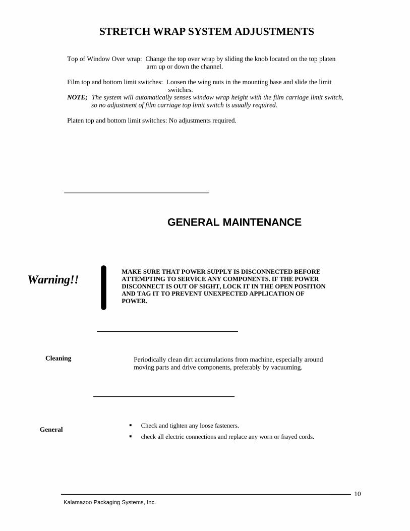
GENERAL MAINTENANCE
§ Check and tighten any loose fasteners.
§ check all electric connections and replace any worn or frayed cords.
Kalamazoo Packaging Systems, Inc.
Periodically clean dirt accumulations from machine, especially around moving parts and drive components, preferably by vacuuming.
Cleaning
MAKE SURE THAT POWER SUPPLY IS DISCONNECTED BEFORE ATTEMPTING TO SERVICE ANY COMPONENTS. IF THE POWER DISCONNECT IS OUT OF SIGHT, LOCK IT IN THE OPEN POSITION AND TAG IT TO PREVENT UNEXPECTED APPLICATION OF POWER.
Warning!!
General
STRETCH WRAP SYSTEM ADJUSTMENTS
Top of Window Over wrap: Change the top over wrap by sliding the knob located on the top platen arm up or down the channel. Film top and bottom limit switches: Loosen the wing nuts in the mounting base and slide the limit switches. NOTE; The system will automatically senses window wrap height with the film carriage limit switch, so no adjustment of film carriage top limit switch is usually required. Platen top and bottom limit switches: No adjustments required.

11 Kalamazoo Packaging Systems, Inc.
Bearings § The bearings have been greased at the factory and are ready to run. It is
recommended that all mounted bearings and support wheels be relubricated with #3 lithium base grease every three months.
Chains § Clean, lubricate and adjust chains every month. Chain should be lubricated
with a penetrating type commercial chain lube. Gear Reducers § For new reducers, change the oil 120 hours after the reducer starts operating
(based on 8 hours per day of operation). After the first oil change, change oil every 2000 operating hours, or every six months, whichever occurs first.
Temperature Lubricant 25° - 125° F AGMA #8 15° - 60° F AGMA #7 Certain conditions (dust, water, etc.) may require a change of lubricating periods as dictated by experience.
Lubrication
CHAIN TENSIONS
Film Lift Chain Tension - Loosen chain adjuster axle located at the top of the tower, move the chain adjuster on both sides equally until chain is tight, retighten the axle nut ( DO NOT OVER TIGHTEN). Film Lift Motor Chain Tension - Remove back lower cover of machine. Loosen four mounting bolts, tighten chain and retighten mounting bolts. Platen Lift Chain Tension - Loosen chain adjuster axle located at the top of the tower, move the chain adjusters on both sides equally until chain is tight, retighten the axle nut ( Do NOT OVER TIGHTEN). Platen Motor Chain Tension - Remove back lower cover of machine. Loosen four mounting bolts, tighten chain and retighten mounting bolts. Turntable Drive Chain - Loosen slide mounting bolts, tighten chain with tensioning screw provided, retighten mounting bolts.

12
Kalamazoo Packaging Systems, Inc.
Technical and Customer Service is available from Kalamazoo Packaging Systems, Inc., Monday thru Friday 7:30 A.M. to 4:00 P.M. (EST). Stock is maintained on parts to allow us to ship the same day on most orders. If you have a problem, we want to know about it! Please call and report any difficulties you may encounter. • Local - (616) 534-2600 • National - (800) 253-4625
When any problem develops, review the operating instructions. Diagnose specific problems and review the options below. Machine not running at all.
1. Check wall receptacle for power 2. Check power cord for cut. (Fork Lift Trucks damage cords.) 3. Push in the E-STOP button after 30 sec. turn to reset the E-Stop button This will reset the drives and the PLC. 4. Check all fuses. (Only replace with the same type and rating.) System does not automatically stop.
1. Check limit switch under the turntable disc to see if the limit switch arm is hitting the cam. Carriage Malfunction:
1. Push stop to clear the system and try operating it again. DISCONNECT POWER FROM MACHINE. 2. Check all limit switches for damage, sticking or internal shorts. 3. Open cabinet and check that all relays are firmly seated in their bases. 4. Visually inspect for loose wires and for any signs of arcing or burning of any of the components. 5. It is advisable to call for technical assistance at this time. (616) 534-2600.
TROUBLESHOOTING

13
14

15
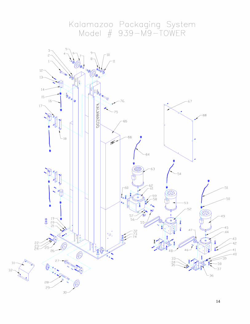
ITEM PART# GRAINGER DESCRIPTION QTY
1 338521 TOP SHAFT 5/8-11 x 4-1/2” HEX HEAD CAP SCREW 2
2 L144 5/8 SAE WASHER 2
3 107993 TOWER CHAIN ADJUSTER (LEFT) 2
4 338252 TOWER TOP SPROCKET SHORT SPACER 2
5 120650 5/8”x 1-3/8” PRE. FLANGE BEARING 4
6 939-05 50B22 TOWER TOP SPROCKET (KPS) 2
7 338253 TOWER TOP SPROCKET LONG SPACER 2
8 L141 5/8-11 NUT 2
9 L142 5/8 LOCK WASHER 2
10 L144 5/8 SAE WASHER 2
11 107994 TOWER CHAIN ADJUSTER (RIGHT) 2
12 L6 6/32 x 1-3/4” MACHINE SCREW 8
13 210881 5B058 1.5 LIMIT SWITCH LEVER ARM 4
14 210890 5B084 H.D. LIMIT SWITCH 4
15 210345 CORD GRIP 1/2” NPT 8
16 209850 1W661 16/3 SJ CORD 4
17 G13 1/4-20 WING NUT 4
18 939-04-1
LIMIT SWITCH BRACKET (HD) 2
19 L48 5/16 USS WASHER 2
20 L47 5/16 LOCK WASHER 2
21 L54 5/16-18x 1-1/2” SET SCREW 2
22 G35 3/8-24x 1-1/4” HEX HEAD CAP SCREW 8
23 G32 3/8 LOCK WASHER 8
24 G33 3/8 USS WASHER 8
25 121050 3/4” 2-BOLT FLANGE BEARING 4
26 107990 50B22x 3/4” SPROCKET 2
27 107975 50B12x 3/4” SPROCKET (SPIRAL) 1
28 338522 BOTTOM SHAFT 2
29 L2 3/16”x 3/16”x 3/4” KEYWAY 4
Kalamazoo Packaging Systems

16
Kalamazoo Packaging Systems PARTS MANUAL: 939-M9 TOWER
ITEM PART# GRAINGER DESCRIPTION QTY
30 107990 50B22x 3/4” SPROCKET (PLATEN) 1
31 939-24 939 TOWER CHAIN GUARD 1
32 G16 1/4-20 x 3/4” MACHINE SCREW 2
33 G16 1/4” SAE WASHER 8
34 G15 1/4” LOCK WASHER 8
35 G18 1/4-20x 3/4” HEX HEAD CAP SCREW 8
36 351 LIFT MOTOR MOUNT 2
37 L48 5/16 USS WASHER 8
38 L47 5/16 LOCK WASHER 8
39 L48 5/16-18x 3/4” HEX HEAD CAP SCREW 8
40 L48 5/16 USS WASHER 1
41 L53 5/16-18x 1-1/2” HEX HEAD CAP SCREW 1
42 G41 3/8-16x 1” HEX HEAD CAP SCREW 8
43 G32 3/8” LOCK WASHER 8
44 106110 4Z285 50:1 R/A REDUCER (FILM LIFT) 1
45 L2 3/16”x 3/16”x 3/4” KEYWAY 2
46 L2 3/16”x 3/16”x 3/4” KEYWAY 2
47 107900 50B10x 5/8” SPROCKET 2
48 109500 #50 CHAIN x 1
49 105313 2N916 230v 3ph. 1/2hp. TEFC MOTOR (FILM LIFT) 1
50 210340 2A247 CORD GRIP 6
51 3ea. 14ga. RED MTW WIRE/ 1ea. 14ga. GREEN 1
52 106100 4Z284 60:1 R/A REDUCER (TOP PLATEN) 1
53 105313 2N916 230v 3ph. 1/2hp. TEFC MOTOR (PLATEN) 1
54 3ea. 14ga. RED MTW WIRE/ 1ea. 14ga. GREEN 1

17
ITEM PART # GRAINGER DESCRIPTION QTY
55 G43-1 3/8-16x 1-1/2” HEX HEAD CAP SCREW w/ CAN‘T TWISTPLATE
2
56 G43 3/8-16x 1-1/2” HEX HEAD CAP SCREW 2
57 L65 3/8” USS WASHER 8
59 G40 3/8-16x 1” HEX HEAD CAP SCREW 4
58 L64 3/8” LOCK WASHER 4
60 L63 3/8-16 NYLOCK NUT 4
61 106060 4Z616 31:1 INLINE REDUCER (TURNTABLE) 1
62 L2 3/16”x 3/16”x 3/4” KEYWAY 1
63 105313 2N916 230v 3ph. 1/2hp. TEFC MOTOR (TURNTABLE) 1
64 3ea. 14ga. RED MTW WIRE/ 1ea. 14ga. GREEN 1
65 939-M9 939-M9 TOWER & CABINET 1
66 206000 KPS NAME PLATE 1
67 939-03 939 BASE CABINET COVER 1
68 G16-01 1/4-20 BUTTON HEAD CAP SCREW 8
Kalamazoo Packaging Systems PARTS MANUAL: 939-M9 TOWER

18

19
Kalamazoo Packaging Systems PARTS MANUAL: 939-M9 TABLE DISC
ITEM PART # GRAINGER DESCRIPTION QTY
1 356000 TURNTABLE DISC 3/8” FL. PL. x 60” 1
2 L130 1/2-13 x 1-1/2” FLAT HEAD SOCKET CAP SCREW
4
3 939-28a TURNTABLE DRIVEN SPROCKET 1
4 G38 3/8-16 NYLOCK NUT 4
5 G32 3/8 LOCK WASHER 4
6 G33 3/8 USS WASHER 4
7 121140 5X699 1” 4-BOLT FLANGE BEARING 1
8 3/8-16x 1-1/2” ALEN HEAD FLAT 4
9 121955 2” TURNTABLE ROLLERS 6
10 L126 1/2-13 NYLOCK NUT 6
11 L132 1/2-13x 2-1/4” HEX HEAD CAP SCREW gr.8 6
12 L6 6/32 x 1-3/4” MACHINE SCREW 2
13 210851 3A096 LIMIT SWITCH (SPRING ARM) 1
14 210345 CORD GRIP 1/2” NPT 1
15 209850 1W661 16/3 SJ CORD 1
16 108500 #50 TURNTABLE CHAIN 1
17 108002 50B12x1” SPROCKET 1
18 l3 1/4”x 1/4”x 3/4” KEYWAY 1
19 G79 3/4-10 NUT 4
20 939-25a 939 TURNTABLE BASE 1
21 939-19 LOWER FIXTURE PLATE 1
22 939-19 LOWER FIXTURE 2
23 800090 4-PRONG POSITIONING KNOB 2
24 G40 3/8-16x 1” HEX HEAD CAP SCREW 3
25 G32 3/8 LOCK WASHER 3
26 G33 3/8 USS WASHER 3

20

21
ITEM PART # DESCRIPTION QTY
1 939-07-001 KNOB SLIDE PLATE 1
2 G46 3/8” FENDER WASHER 1
3 5269-1400 POSITION LOCKING KNOB w/ 3/8-24x 1-1/4 SET SCREW
1
4 121750 3/4” CAM ROLLER 4
5 121760 3/4” EXC. CAM ROLLER 4
6 G33 3/8 SAE WASHER 8
7 H5 3/8-24 NYLOCK JAM NUT 8
8 210345 CORD GRIP 3
9 210050 16/3 COILED CORD 1
10 G33 3/8 SAE WASHER 8
11 G38 3/8-16 NUT 4
12 3/8-16 x 1.0” BRASS WEAR SCREW 4
13 209850 16/3 SJ CORD 1
14 338530 PLATEN FIXTURE STOP CALLOR 1
15 338531 PLATEN FIXTURE STOP CUP 1
16 G35 3/6-24x 1-1/4” HEX HEAD CAP SCREW 4
17 G32 3/8 LOCK WASHER 4
18 G33 3/8 USS WASHER 4
19 121071 1-1/4” 2-BOLT FLANGE BEARING 2
20 G8 10/32 x 1-1/2” MACHINE SCREW 2
21 210890 H.D. LIMITS SWITCH 1
22 210892 H.D. LIMITS SWITCH LEVER ARM (ADJUSTABLE)
1
23 939-07 939 TOP PLATEN BOOM ARM 1
24 939-18 939 TOP FIXTURE 1
25 939-18-01 939 TOP FIXTURE PLUNGER 1
Kalamazoo Packaging Systems PARTS MANUAL: 939-M9 TOP PLATEN BOOM ARM

22

23
Kalamazoo Packaging Systems PARTS MANUAL: 939-M9 SUB PANEL
ITEM PART# GRAINGER DESCRIPTION QTY
1 209700 TERMINAL STRIP 12 POLE 1
2 220176 MITSUBISHI PLC 1
3 208250 2PDT 10a. RELAY 1
4 208260 8-PIN BASE 1
5 210772 2-POLE FUSE HOLDER 1
6 210776 1a. FUSE (PLC) 1
7 210825 4a. FUSE (BRAKE) 1
8 131200 90/180v. DC CONTROLLER (BRAKE) 1
9 208050 2PDT 30a. RELAY (MCR) 1
10 210771 1-POLE FUSE HOLDER 1
11 210792 25a FUSE (MAIN) 1
12 210744 40a. DISCONNECT 1
13 210771 1-POLE FUSE HOLDER 1
14 210825 4a. FUSE (FILM LIFT) 1
15 131275 1/2hp 110v 1ph. input 230v 3ph. output AC DRIVE 1
16 210771 1-POLE FUSE HOLDER 1
17 210825 4a. FUSE (TOP PLATEN) 1
18 131275 1/2hp 110v 1ph. input 230v 3ph. output AC DRIVE 1
19 210771 1-POLE FUSE HOLDER 1
20 210825 4a. FUSE (TURNTABLE) 1
21 131275 1/2hp 110v 1ph. input 230v 3ph. output AC DRIVE 1
22-24 209700 TERMINAL STRIP 12 POLE 3

24

25
Kalamazoo Packaging Systems PARTS MANUAL: 939 CONTROL CONSLOE
ITEM PART# DESCRIPTION QTY
1 939-M9a DECAL 939-M9a CONTROL CONSOLE DECAL 1
2 207110 E-STOP BUTTON PUSH OFF/TURN TO RESET 1
4 207103 JOG 3-POSITION SELECTOR (PROGRAM) 1
5 207100 JOG 2-POSITION SELECTOR (TABLE JOG) 1
6 207001 GREEN PUSH BUTTON (START) 1
7 207057 WHITE PUSH BUTTON (PLATEN RAISE) 1
8 207058 YELLOW PUSH BUTTON (FILM RAISE) 1
9 207055 RED PUSH BUTTON(CYCLE INTERRUPT) 1
10 207060 BLACK PUSH BUTTON (PLATEN LOWER) 1
11 207056 BLUE PUSH BUTTON (FILM LOWER) 1
12 939-12a CONTROL CONSOLE NEMA 12 ENCLOSURE 1
13 939-17 CONTROL CONSOLE ARM 1
14 G29 5/16-18x 1-1/2” FLAT HEAD 4
3 207050 RED MUSHROOMPUSH BUTTON (STOP) 1
1 939-JUMBO 939-JUMBO CONTROL CONSOLE DECAL 1

26

27
ITEM PART# DESCRIPTION QTY
1 G8 10/32 x 1-1/2” MACHINE SCREW 2
2 210890 H.D. LIMITS SWITCH 1
3 210892 H.D. LIMITS SWITCH LEVER ARM (ADJUSTABLE)
1
4 210050 16/3 COILED CORD 1
5 210345 CORD GRIP 1
6 L3 3/16x 3/16x 3/4” KEYWAY 1
7 130500 3-3/4 90v DC BRAKE 1
8 939-06 TOP PLATE w/ NEMA 1 BOX 1
9 G40 3/8-16 x 1 HEX HEAD CAP SCREW 3
10 G32 3/8 LOCK WASHER 4
11 G33 3/8 SAE WASHER 4
12 120650 5/8x 1-3/8 PER. FLANGE BEARING 2
13 G74 5/8 SPRING WASHER 1
14 349-R 30” PRE. VARIABLE TENSION BRAKE ROLLER 1
15 120600 5/8x 1-3/8 FLANGE BEARING 2
16 349-IR 30” PRE. VARIABLE TENSION IDLER ROLLER 1
17 349-IRS 5/8 G&P x 31-1/2 IDLER ROLLER SHAFT 1
18 3/8-16x 1-1/4 ALEN HEAD CAP SCREW 1
19 G29 5/16-18x 1-1/2 FLAT HEAD CAP SCREW 2
20 991-20 2.95 DIA x 20 FILM CORE 1
21 120860 3 THRUST WASHER 1
22 121750 3/4” CAM ROLLER 4
23 121760 3/4” EXC. CAM ROLLER 4
24 G33 3/8 SAE WASHER 8
25 H5 3/8-24 NYLOCK JAM NUT 8
26 G33 3/8 SAE WASHER 4
27 G38 3/8-16 NUT 4
28 3/8-16 x 1.0” BRASS WEAR SCREW 4
29 939-06 BASE PLATE 1
PARTS MANUAL: PRECESSION VARIABLE TENSION HEAD
Kalamazoo Packaging Systems PARTS MANUAL: PRECESSION VARIABLE TENSION HEAD

28

29

30

31

32
Model # 939-M9 Window / Panel Stretch Wrapper Timers Timer # Description Time T0 Bottom timer short program K50 T1 Bottom timer tall program K60 T2 Bottom timer large program K70 T3 Top timer short program K10 T4 Top timer tall program K70 T5 Top timer large program K80 T6 Autostop short program K20 T7 Autostop tall program K20 T8 Autostop large program K50 T9 Time to go pass autostop limit switch K10 DO NOT CHANGE
T10 Film tension start delay K30 T11 Film tension off delay K80 To make changes to the timers call Kalamazoo Packaging System, Inc. 1(800)253-4625

33

34

35

36
37

38

39

40

41

42

43


