20
LP12_5TL15788_06/10 LP1207 LP1208 LP1210 LAND PLANES OPERATOR'S MANUAL

LP12_5TL15788_06/10
LP1207LP1208LP1210
LAND PLANESO P E R A T O R ' S M A N U A L

Introduction ii
TO THE DEALER:
Assembly and proper installation of this product is the responsibility of the Frontier dealer. Read manu-al instructions and safety rules. Make sure all items on the Dealer’s Pre-Delivery and Delivery Check Lists in the Owner’s/Operator’s Manual are completed before releasing equipment to the owner.
The dealer must complete the Warranty Registration located on the Frontier website.
TO THE OWNER:
Read this manual before operating your Frontier equipment. The information presented will prepare you to do a better and safer job. Keep this manual handy for ready reference. Require all operators to read this manual carefully and become acquainted with all the adjustment and operating procedures before attempting to operate. Replacement manuals can be obtained from your Frontier dealer.
The equipment you have purchased has been carefully engineered and manufactured to provide dependable and satisfactory use. Like all mechanical products, it will require cleaning and upkeep. Lubricate the unit as specified. Observe all safety information in this manual and safety decals on the equipment.
For service, your authorized Frontier dealer has trained mechanics, genuine Frontier service parts, and the necessary tools and equipment to handle all your needs.
Use only genuine Frontier service parts. Substitute parts will void the warranty and may not meet stan-dards required for safe and satisfactory operation. Record the model number and serial number of your equipment in the spaces provided:
Model:____________________________________ Date of Purchase:_________________
Serial Number: (see Safety Decal section for location)_______________________________Provide this information to your dealer to obtain correct repair parts.
Throughout this manual, the term IMPORTANT is used to indicate that failure to observe can cause damage to equipment. The terms CAUTION,WARNING and DANGER are used in conjunction with the Safety-Alert Symbol, (a triangle with an exclamation mark), to indicate the degree of hazard for items of personal safety.
DANGER
WARNING
CAUTION
IMPORTANTNOTE
This Safety-Alert Symbol indicates a hazard and means ATTENTION!BECOME ALERT! YOUR SAFETY IS INVOLVED!
Indicates an imminently hazardous situation that, if not avoided, will result in death or serious injury.
Indicates a potentially hazardous situation that, if not avoided, could result in death or serious injury, and includes hazards that are exposed when guards are removed.
Indicates a potentially hazardous situation that, if not avoided, may result in minor or moderate injury.
Indicates that failure to observe can cause damage to equipment.
Indicates helpful information.

Table of Contents
TABLE OF CONTENTS
INTRODUCTION / GENERAL INFORMATION. . . . . . . . . . . . . . . . . . . . . . . . . . . . . . . . . . . . . . . . . . ii
SPECIFICATIONS. . . . . . . . . . . . . . . . . . . . . . . . . . . . . . . . . . . . . . . . . . . . . .1
SAFETY DECALS . . . . . . . . . . . . . . . . . . . . . . . . . . . . . . . . . . . . . . . . . . . . . . . 2 - 3
SAFETY RULES . . . . . . . . . . . . . . . . . . . . . . . . . . . . . . . . . . . . . . . . . . . . . . 4 - 6
DEALER INSTRUCTIONS . . . . . . . . . . . . . . . . . . . . . . . . . . . . . . . . . . . . . . . . . . . . 7
OPERATION . . . . . . . . . . . . . . . . . . . . . . . . . . . . . . . . . . . . . . . . . . . . . . . . . 8 - 11
OWNER SERVICE . . . . . . . . . . . . . . . . . . . . . . . . . . . . . . . . . . . . . . . . . . . . . . . . . 12
PARTS CATALOG . . . . . . . . . . . . . . . . . . . . . . . . . . . . . . . . . . . . . . . . . . . . . . . . 13 - 14
BOLT SIZE AND BOLT TORQUE CHART . . . . . . . . . . . . . . . . . . . . . . . . . . . . . . . . . . 15
NOTES . . . . . . . . . . . . . . . . . . . . . . . . . . . . . . . . . . . . . . . . . . . . . . . . . . . . 16
The purpose of this manual is to assist you in operating and maintaining your Land Plane. Read it carefully. It furnishes infor-mation and instructions that will help you achieve years of dependable perfor-mance.
These instructions have been compiled from field experience and engineering data. Some information may be general in nature, due to unknown and varying oper-ating conditions. However, through expe-rience and these instructions, you should be able to develop procedures suitable to
your particular situation.The illustrations and data used in this manual were current at the time of print-ing. However, due to possible inline pro-duction changes, your machine may vary slightly in detail. We reserve the right to redesign and change the machines as may be necessary without notification.
Throughout this manual, references are made to right and left direction. These are determined by standing behind the tractor facing the direction of forward travel.
GENERAL INFORMATION
1 Specifications
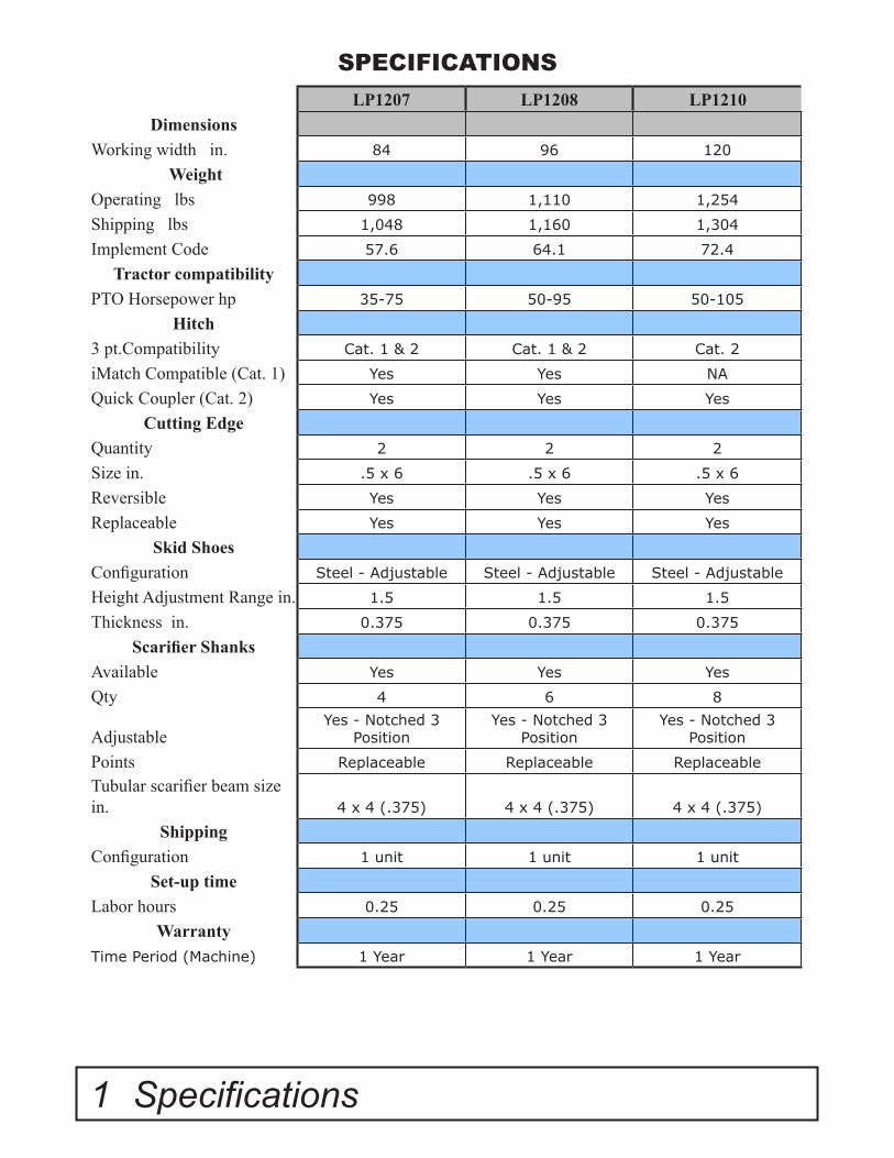
SPECIFICATIONSLP1207 LP1208 LP1210
DimensionsWorking width in. 84 96 120
WeightOperating lbs 998 1,110 1,254
Shipping lbs 1,048 1,160 1,304
Implement Code 57.6 64.1 72.4
Tractor compatibilityPTO Horsepower hp 35-75 50-95 50-105
Hitch3 pt.Compatibility Cat. 1 & 2 Cat. 1 & 2 Cat. 2
iMatch Compatible (Cat. 1) Yes Yes NA
Quick Coupler (Cat. 2) Yes Yes Yes
Cutting EdgeQuantity 2 2 2
Size in. .5 x 6 .5 x 6 .5 x 6
Reversible Yes Yes Yes
Replaceable Yes Yes Yes
Skid ShoesConfiguration Steel - Adjustable Steel - Adjustable Steel - Adjustable
Height Adjustment Range in. 1.5 1.5 1.5
Thickness in. 0.375 0.375 0.375
Scarifier ShanksAvailable Yes Yes Yes
Qty 4 6 8
AdjustableYes - Notched 3
PositionYes - Notched 3
PositionYes - Notched 3
Position
Points Replaceable Replaceable Replaceable
Tubular scarifier beam size in. 4 x 4 (.375) 4 x 4 (.375) 4 x 4 (.375)
Shipping Configuration 1 unit 1 unit 1 unit
Set-up timeLabor hours 0.25 0.25 0.25
WarrantyTime Period (Machine) 1 Year 1 Year 1 Year
Safety Decals 2
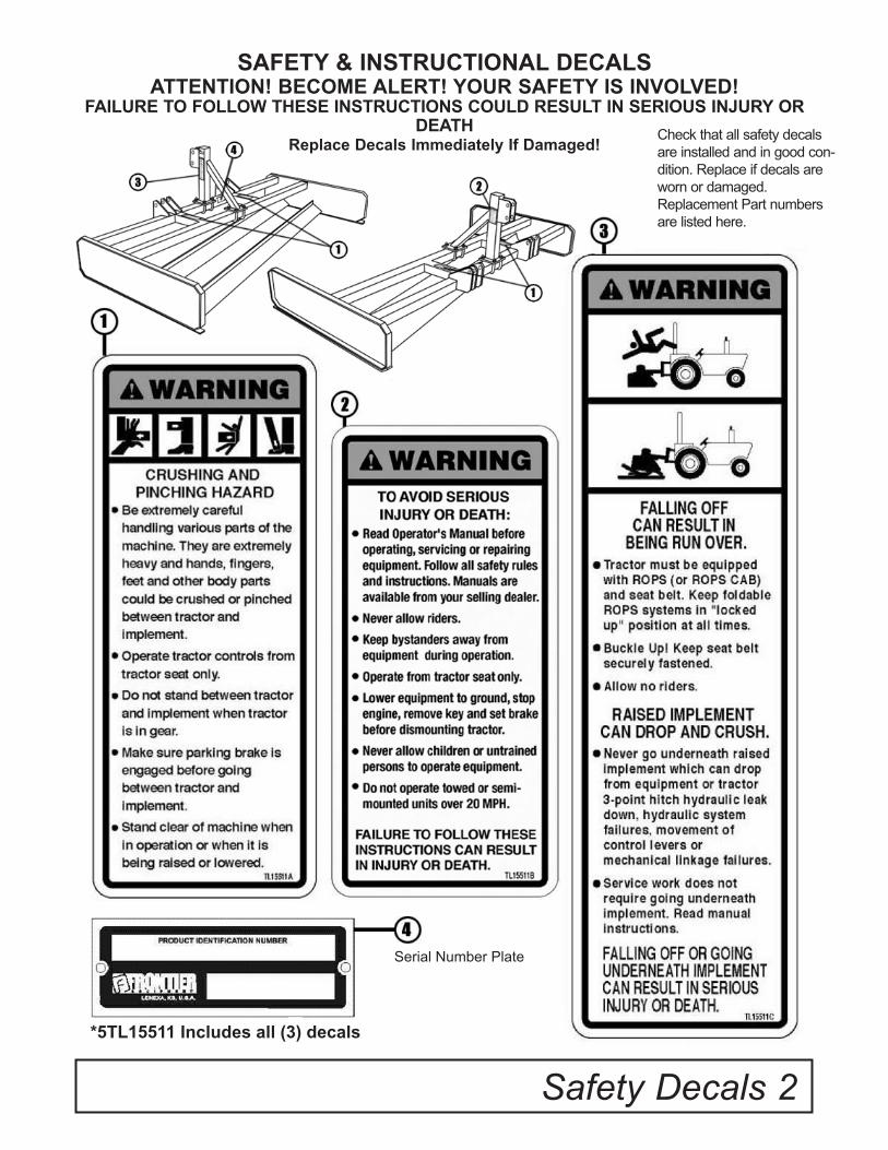
SAFETY & INSTRUCTIONAL DECALSATTENTION! BECOME ALERT! YOUR SAFETY IS INVOLVED!
FAILURE TO FOLLOW THESE INSTRUCTIONS COULD RESULT IN SERIOUS INJURY OR DEATH
Replace Decals Immediately If Damaged! Check that all safety decals are installed and in good con-dition. Replace if decals are worn or damaged. Replacement Part numbers are listed here.
Serial Number Plate
*5TL15511 Includes all (3) decals

3 Safety Decals
SAFETY REFLECTOR DECALSATTENTION! BECOME ALERT! YOUR SAFETY IS INVOLVED!
FAILURE TO FOLLOW THESE INSTRUCTIONS COULD RESULT IN SERIOUS INJURY OR DEATH
Replace Decals Immediately If Damaged!
Only on LP1208 and LP1210
9” RED REFLECTORS5TL15199
Check that all reflector decals are installed and in good condition. Replace if decals are
worn or damaged.
9” YELLOW REFLECTORS5TL15200
Check that all reflector decals are installed and in good condition. Replace if decals are
worn or damaged.

Safety Rules 4
SAFETY RULESATTENTION! BECOME ALERT! YOUR SAFETY IS INVOLVED!
Safety is a primary concern in the design and manufacture of our products. Unfortunately, our efforts to provide safe equipment can be wiped out by an operator’s single careless act.
In addition to the design and configuration of equip-ment, hazard control and accident prevention are dependent upon the awareness, concern, judge-ment, and proper training of personnel involved in the operation, transport, maintenance and storage of equipment.
It has been said “The best safety device is an informed, careful operator.”We ask you to be that kind of operator.
TRAINING
• Safety instructions are important! Read all attach-ment and power unit manuals; follow all safety rules and safety decal information. (Replacement manuals are available from selling dealer.) Failure to follow instructions or safety rules can result in serious injury or death.
• If you do not understand any part of this manual and need assistance, see your dealer.
• Operators must be instructed in and be capable of the safe operation of the equipment, its attach-ments, and all controls. Do not allow anyone to operate this equipment without proper instruc-tions.
• Never allow children or untrained persons to operate equipment.
• Train all new personnel and review instruction’s frequently with existing workers. A person who has not read and understood all operating and safety instructions is not qualified to operate the machine. An untrained operator exposes himself and bystand-ers to possible serious injury or death.
PREPARATION
• Always wear relatively tight and belted clothing to avoid getting caught in moving parts.
Wear sturdy, rough-soled work shoes and protec-tive equipment for eyes, hair, hands, hearing, and head; and respirator or filter mask where appropriate.
• Make sure attachment is properly secured, adjusted, and in good operating condition.
• Power unit must be equipped with ROPS or ROPS cab and seat belt. Keep seat belt securely fastened. Falling off power unit can result in death from being run over or crushed. Keep fold-able ROPS system in “locked up” position at all times.
• A minimum 20% of tractor and equipment weight must be on the tractor front wheels when attachments are in transport position. Without this weight, tractor could tip over, causing per-sonal injury or death. The weight may be attained with a loader, front wheel weights, ballast in tires or front tractor weights. Weigh the tractor and equipment. Do not estimate.
TRANSPORTATION
• Always comply with all state and local laws gov-erning highway safety and lighting and marking requirements.
• Never allow riders on power unit or attachment.
• Do not operate or transport on steep slopes.
• Use extreme care and reduce ground speed on slopes and rough terrain.
• Do not operate or transport equipment while under the influence of alcohol or drugs. Consult your doctor about operating this machine while taking prescription medications.
OPERATION
• Never go underneath equipment (lowered to the ground or raised) unless it is properly

SAFETY RULESATTENTION! BECOME ALERT! YOUR SAFETY IS INVOLVED!
OPERATION (cont’d) blocked and secured. Never place any part of the body underneath equipment or between moveable parts even when the engine has been turned off. Hydraulic system leak down, hydrau-lic system failures, mechanical failures, or move-ment of control levers can causeequipment to drop or rotate unexpectedly and cause severe injury or death.
• Always comply with all state and local laws gov-erning highway safety and lighting and marking requirements.
• Operate only in daylight or good artificial light.
• Keep bystanders away from equipment.
• Keep hands, feet, hair, and clothing away from equipment while engine is running. Stay clear of all moving parts.
• Power unit must be equipped with ROPS or ROPS cab and seat belt. Keep seat belt securely fastened. Falling off power unit can result in death from being run over or crushed. Keep foldable ROPS system in “locked up” position at all times.
• Never allow riders on power unit or attachment.
• Always sit in power unit seat when operating controls or starting engine. Securely fasten seat belt, place transmission in neutral, engage brake, and ensure all other controls are disengaged before starting power unit engine.
• Look down and to the rear and make sure area is clear before operating in reverse.
• Use extreme care when working close to fences, ditches, other obstructions, or on hillsides.
• Do not operate or transport on steep slopes.
• Do not stop, start, or change directions sud-denly on slopes.
Always operate down slopes; never across the face.
• Use extreme care and reduce ground speed on slopes and rough terrain.
• Keep alert and watch the front as well as therear when operating.
• When making gang adjustments, be careful to keep hands and feet clear of sliding parts and possible pinch points.• Stop power unit and equipment immediately upon striking an obstruction. Turn off engine, remove key, inspect, and repair any damage before resuming operation.
• Before leaving operator’s seat, lower lift arms and put attachment on the ground. Engage brake, stop engine, remove key, and remove seat belt.
MAINTENANCE
• Always wear relatively tight and belted clothing to avoid getting caught in moving parts. Wear sturdy, rough-soled work shoes and protective equipment for eyes, hair, hands, hearing, and head; and respirator or filter mask where appropri-ate.
• Never go underneath equipment (lowered to the ground or raised) unless it is properly blocked and secured. Never place any part of the body under-neath equipment or between moveable parts even when the engine has been turned off. Hydraulic system leak down, hydraulic system failures, mechanical failures, or movement of control levers can cause equipment to drop or rotate unexpect-edly and cause severe injury or death.
• When performing maintenance or repairs make sure the equipment is in the lowered position and properly blacked and secured to prevent rolling.
5 Safety Rules

Safety Rules 6
MAINTENANCE(cont’d)Failure to do so can cause serious injury or death.
• Make sure attachment is properly secured, adjusted, and in good operating condition.
• Before leaving operator’s seat, lower lift arms and put attachment on the ground. Engage brake, stop engine, remove key, and remove seat belt.
• Never perform service or maintenance with engine running.
• Keep all persons away from operator control area while performing adjustments, service, or maintenance.
• Tighten all bolts, nuts, and screws to torque
chart specifications. Check that the equipment is properly attached to the power source and that the equipment is in a safe condition before putting unit into service.
STORAGE
• Block equipment securely for storage.
• Keep children and bystanders away from stor-age area.
SAFETY RULESATTENTION! BECOME ALERT! YOUR SAFETY IS INVOLVED!

7 Dealer Instructions
Pre-Assembly
Top Link Mast Assembly
Reference Figure 6 (Pg. 13).
The top link mast should be centered evenly between the two inside hitch ears. Once cen-tered, insert the four 5TL11971 u-bolts and fasten with the eight 5TLT31 lock washers and 5TLT27 lock nuts.
Installing Scarifier Shanks in the Land PlaneRemove scarifier shanks and shank keys fromcarton inside land plane.
Block up machine by placing two 4” x 4” blocks under each side frame of the land plane.
Insert the scarifier shank in the shank hole from the bottom up.
Note: The scarifier shank has four notches for adjustments. The bottom notch is for transport.The top three notches are for ground penetra-tion to be determined by the user.
After inserting scarifier shank, place shank keyon the rear side of shank. This will prevent the shank from working loose.
Dealer Checklist(Dealer’s Responsibility)Inspect the equipment thoroughly after assem-bly to be certain it is set up properly before delivering it to the customer. The following check list is a reminder of points to inspect.
Check off each item if it is found satisfactory orafter proper adjustment is made.____ Check that all safety decals are installedand in good condition. Replace if damaged.____ Check all bolts to be sure they are tight.____ Check that all cotter pins and safety pinsare properly installed.
____It is important for the dealer to visually check and make sure all parts are in tact prior to delivery to customer.____ Show customer the safe, proper proce-dures to be used when mounting, dismounting,and storing equipment.____ For mounted units, add wheel weights,ballast in front tires, and/or front tractor weightto enhance front end stability. A minimum 20%of tractor and equipment gross weight must beon front tractor wheels. When adding weight to attain 20% of tractor and equipment weight on front tractor wheels, you must not exceed the ROPS weight certification. Weigh the tractor and equipment. Do not estimate!____ Show customer how to make adjust-ments.____ Present Owner’s/Operator’s Manual andrequest that customer and all operators read itbefore operating equipment. Point out the man-ual safety rules, explain their meanings and emphasize the increased safety hazards that exist when safety rules are not followed.____ Point out the safety decals. Explain their meaning and the need to keep them in place and in good condition. Emphasize the increased safety hazards when instructions are not fol-lowed.____ Explain to customer the potential crushing hazards of going underneath raised equipment. Instruct customer that service work does not require going underneath unit and never to do so.
DEALER INSTRUCTIONS
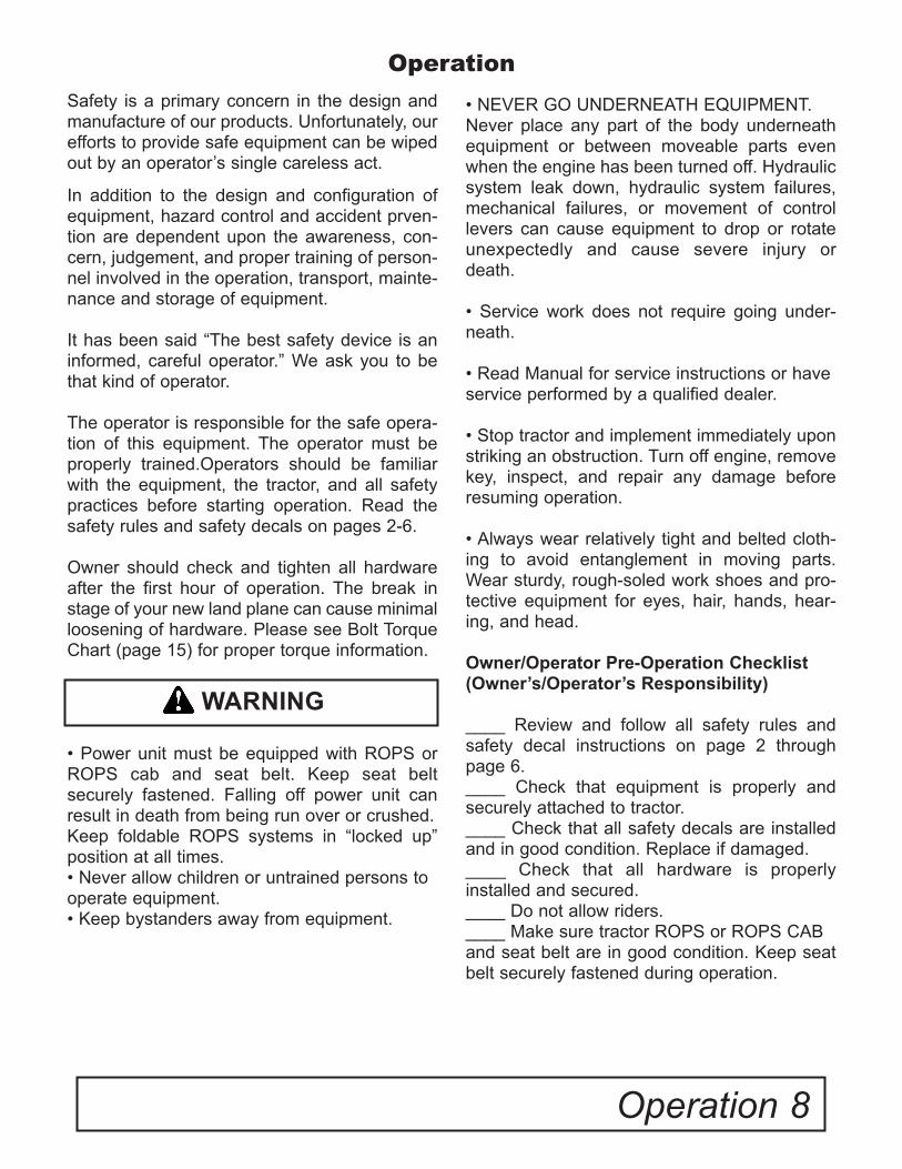
• NEVER GO UNDERNEATH EQUIPMENT.Never place any part of the body underneath equipment or between moveable parts even when the engine has been turned off. Hydraulic system leak down, hydraulic system failures, mechanical failures, or movement of control levers can cause equipment to drop or rotate unexpectedly and cause severe injury or death.
• Service work does not require going under-neath.
• Read Manual for service instructions or haveservice performed by a qualified dealer.
• Stop tractor and implement immediately uponstriking an obstruction. Turn off engine, remove key, inspect, and repair any damage before resuming operation.
• Always wear relatively tight and belted cloth-ing to avoid entanglement in moving parts. Wear sturdy, rough-soled work shoes and pro-tective equipment for eyes, hair, hands, hear-ing, and head.
Owner/Operator Pre-Operation Checklist(Owner’s/Operator’s Responsibility)
____ Review and follow all safety rules and safety decal instructions on page 2 through page 6.____ Check that equipment is properly and securely attached to tractor.____ Check that all safety decals are installed and in good condition. Replace if damaged.____ Check that all hardware is properly installed and secured.____ Do not allow riders.____ Make sure tractor ROPS or ROPS CABand seat belt are in good condition. Keep seat belt securely fastened during operation.
Operation 8
Safety is a primary concern in the design and manufacture of our products. Unfortunately, our efforts to provide safe equipment can be wiped out by an operator’s single careless act.
In addition to the design and configuration of equipment, hazard control and accident prven-tion are dependent upon the awareness, con-cern, judgement, and proper training of person-nel involved in the operation, transport, mainte-nance and storage of equipment.
It has been said “The best safety device is an informed, careful operator.” We ask you to be that kind of operator.
The operator is responsible for the safe opera-tion of this equipment. The operator must be properly trained.Operators should be familiar with the equipment, the tractor, and all safety practices before starting operation. Read the safety rules and safety decals on pages 2-6.
Owner should check and tighten all hardware after the first hour of operation. The break in stage of your new land plane can cause minimal loosening of hardware. Please see Bolt Torque Chart (page 15) for proper torque information.
• Power unit must be equipped with ROPS or ROPS cab and seat belt. Keep seat belt securely fastened. Falling off power unit can result in death from being run over or crushed.Keep foldable ROPS systems in “locked up” position at all times.• Never allow children or untrained persons to operate equipment.• Keep bystanders away from equipment.
Operation
WARNING
9 Operation
Connecting Land Plane to the Tractor
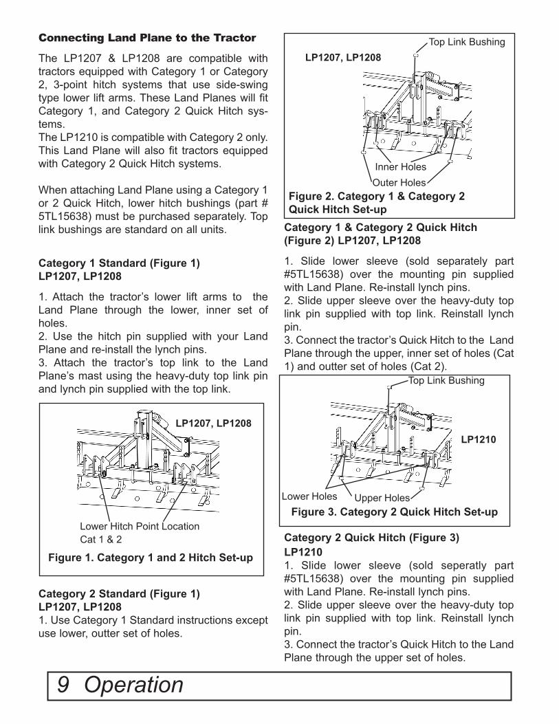
The LP1207 & LP1208 are compatible with tractors equipped with Category 1 or Category 2, 3-point hitch systems that use side-swing type lower lift arms. These Land Planes will fit Category 1, and Category 2 Quick Hitch sys-tems.The LP1210 is compatible with Category 2 only. This Land Plane will also fit tractors equipped with Category 2 Quick Hitch systems. When attaching Land Plane using a Category 1 or 2 Quick Hitch, lower hitch bushings (part # 5TL15638) must be purchased separately. Top link bushings are standard on all units.
Category 1 Standard (Figure 1)LP1207, LP1208
1. Attach the tractor’s lower lift arms to the Land Plane through the lower, inner set of holes.2. Use the hitch pin supplied with your Land Plane and re-install the lynch pins.3. Attach the tractor’s top link to the Land Plane’s mast using the heavy-duty top link pin and lynch pin supplied with the top link.
Category 2 Standard (Figure 1) LP1207, LP12081. Use Category 1 Standard instructions except use lower, outter set of holes.
Category 1 & Category 2 Quick Hitch (Figure 2) LP1207, LP1208
1. Slide lower sleeve (sold separately part #5TL15638) over the mounting pin supplied with Land Plane. Re-install lynch pins.2. Slide upper sleeve over the heavy-duty top link pin supplied with top link. Reinstall lynch pin.3. Connect the tractor’s Quick Hitch to the Land Plane through the upper, inner set of holes (Cat 1) and outter set of holes (Cat 2).
Category 2 Quick Hitch (Figure 3)LP12101. Slide lower sleeve (sold seperatly part #5TL15638) over the mounting pin supplied with Land Plane. Re-install lynch pins.2. Slide upper sleeve over the heavy-duty top link pin supplied with top link. Reinstall lynch pin.3. Connect the tractor’s Quick Hitch to the Land Plane through the upper set of holes.
Figure 1. Category 1 and 2 Hitch Set-up
Figure 2. Category 1 & Category 2 Quick Hitch Set-up
Lower Hitch Point LocationCat 1 & 2
Inner Holes
Top Link Bushing
Outer Holes
LP1207, LP1208
LP1207, LP1208
Figure 3. Category 2 Quick Hitch Set-upUpper Holes
Top Link Bushing
LP1210
Lower Holes
Operation 10
Connecting Land Plane to the Tractor (cont’d.)
Category 2 Standard (Page 9,Figure 3) LP1210
1. Use Category 2 Standard instructions except use lower set of holes.
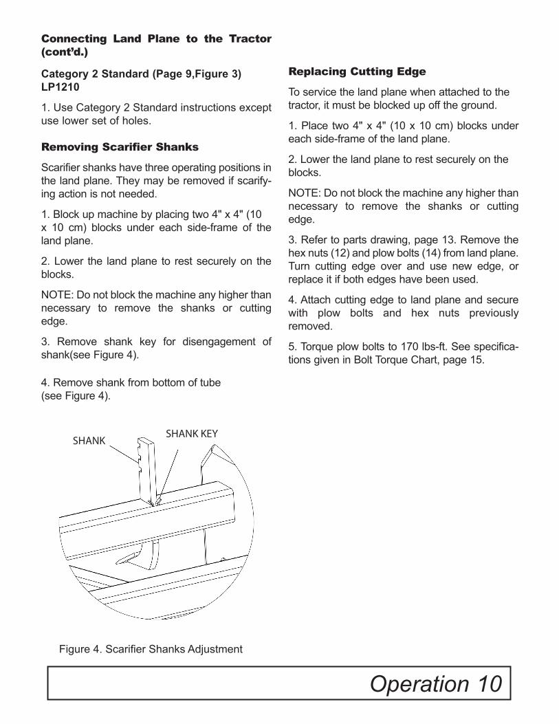
Removing Scarifier Shanks
Scarifier shanks have three operating positions in the land plane. They may be removed if scarify-ing action is not needed.
1. Block up machine by placing two 4" x 4" (10x 10 cm) blocks under each side-frame of the land plane.
2. Lower the land plane to rest securely on the blocks.
NOTE: Do not block the machine any higher than necessary to remove the shanks or cutting edge.
3. Remove shank key for disengagement of shank(see Figure 4).
4. Remove shank from bottom of tube(see Figure 4).
Replacing Cutting Edge
To service the land plane when attached to thetractor, it must be blocked up off the ground.
1. Place two 4" x 4" (10 x 10 cm) blocks under each side-frame of the land plane.
2. Lower the land plane to rest securely on theblocks.
NOTE: Do not block the machine any higher than necessary to remove the shanks or cutting edge.
3. Refer to parts drawing, page 13. Remove the hex nuts (12) and plow bolts (14) from land plane. Turn cutting edge over and use new edge, or replace it if both edges have been used.
4. Attach cutting edge to land plane and secure with plow bolts and hex nuts previously removed.
5. Torque plow bolts to 170 lbs-ft. See specifica-tions given in Bolt Torque Chart, page 15.
Figure 4. Scarifier Shanks Adjustment
SHANKSHANK KEY

Operation (cont’d.)
Adjusting Skid Shoe Weldment
The adjustable skid shoe weldments (part #5TL15786, page 13, Figure 6, Ref. 3) can be adjusted up or down for maximum or no cutting edge penetration. To adjust skid shoe weldments, block up machine by placing two 4” x 4” blocks under each end of the cutting edges on the Land Plane. Loosen the six bolts holding the skid shoes in place (see picture below). Set to desired depth and retighten bolts according to torque chart on page 15.
**The skid shoe weldments (part #5TL15786) on the Land Plane are reversible. This allows the user to change sides when the skid shoe (part #5TL15729) becomes worn. Under normal usage the front side of the skid shoe will wear more than the rear. By reversing the skid plate weldments, this allows for longer life of the skid shoe before having to replace it.
11 Operation
INCORRECTTo much pressure on the rear of the skid shoes.Adjust top link in.
CORRECTPressure is evenly distributed on the front and rear of skid shoes.
INCORRECTTo much pressure on the front of the skid shoes.Adjust top link out.
Adjusting Top LinkAdjust the three point top link so that both blades touch the ground at the same time. In most cases this will give the desired results. To adjust the front blade to cut more than the rear, shorten the three point top link. Lengthen the top link to make the rear blade cut more.
Replacing the Skid Shoes Figure 5
The skid shoes (part #5TL15729) on the Land Plane should be replaced once they are worn down to the skid shoe weldment (part #5TL15786). They can be removed by grinding the welds holding it to the skid shoe weldment. The replacement shoes should then be positioned on the bottom of the skid shoe weldment and welded.
Figure 5

Owner Service 12
• NEVER GO UNDERNEATH EQUIPMENT. Never place any part of the body underneath equipment or between moveable parts even when the engine has been turned off. Hydraulic system leak down, hydraulic system failures, mechanical failures, or movement of control levers can cause equipment to drop or rotate unexpectedly and cause severe injury or death.
• Service work does not require going under-neath.
• Read Manual for service instructions or have service performed by a qualified dealer.
The information in this section is written for oper-ators who possess basic mechanical skills. If you need help, your dealer has trained service techni-cians available. For your protection, read and follow the safety information in this manual.
• Keep all persons away from operator control area while performing adjustments, service, or maintenance.• Before dismounting power unit or performing any service or maintenance, follow these steps: disengage power to equipment, lower the 3 point hitch and all raised components to the ground, operate valve levers to release any hydraulic pressure, set parking brake, stop engine, remove key, and unfasten seat belt.• Always wear relatively tight and belted clothing to avoid entanglement in moving parts. Wear sturdy, rough-soled work shoes and protective equipment for eyes, hair, hands, hearing, and head.
Storage
When storing your land plane make sure the unit is placed on level ground and clear of any obstuctions. Use caution when disconnecting theland plane from the tractor.
WARNING WARNING
WARNING
CAUTION
Owner Service
CAUTION

13 Parts Catalog
Figure 6
PARTS CATALOG
24
Set of Lower HitchBushings For iMatch
(sold seperately)
CAT II Hitch For LP1210 Only
LP1210 Mast Weldment

Parts Catalog 14
Parts Catalog(cont'd.)
ITEM NO. PART NUMBER DESCRIPTION QTY.1 5TL15793 LP1207 MAIN FRAME WELDMENT 1
5TL15780 LP1208 MAIN FRAME WELDMENT 15TL15794 LP1210 MAIN FRAME WELDMENT 1
2 5TL15784 CAT I, MAST WELDMENT, LP1207, LP1208 12A 5TL15795 CAT II, MAST WELDMENT, LP1210 13 5TL15786 ADJ. SKID SHOE WELDMENT 2
3A 5TL15729 WELD ON REPLACEABLE SKID SHOE 24 5TL10705 CUTTING EDGE 84” 2
5TL10706 CUTTING EDGE 96” 25TL13456 CUTTING EDGE 120” 2
5 5TL14835F SCARIFIER SHANK WITH WELD ON POINT *MS6 5TL15413 SHANK KEY *MS7 5TL11971 U-BOLT 48 5TLT31 LOCK WASHER, 3/4” 89 5TLT24 LOCK WASHER, 5/8” *MS
10 5TLT25 LOCK WASHER, 1/2” 1211 5TLT27 HEX NUT, 3/4” 812 5TLT22 HEX NUT, 5/8” *MS13 5TLT26 HEX NUT, 1/2” 1214 5TL10699 PLOW BOLT 5/8” X 1 3/4” GR. 5 *MS15 5TL9225 FLAT WASHER, 1/2” 2416 5TL15782 HEX BOLT 1217 5TL15189 MANUAL TUBE 118 5TL15348 SCREW 219 5TL13257 CAT I & II HITCH PIN LP1207, LP1208 2
19A 5TL11167 CAT II HITCH PIN LP1210 220 5TLVP252 LYNCH PIN 321 5TL15206 CAT I TOP LINK PIN 122 5TL15209 CAT I TOP LINK BUSHING, FOR iMatch HITCH 123 5TL15210 CAT II TOP LINK BUSHING, FOR iMatch HITCH 124 5TL10697 WELD ON POINT *MS25 5TL15208 CAT II TOP LINK PIN 126 5TL15638 SET OF LOWER HITCH iMatch BUSHING 127 5TL15285 FRONTIER LOGO DECAL NOT SHOWN 228 5TL15796 LP1207 MODEL DECAL NOT SHOWN 2
5TL15797 LP1208 MODEL DECAL NOT SHOWN 25TL15798 LP1210 MODEL DECAL NOT SHOWN 2
29 5TL15511 WARNING DECAL (4 DECALS) NOT SHOWN 130 5TL15199 9" RED REFLECTOR NOT SHOWN 231 5TL15200 9" YELLOW REFLECTOR NOT SHOWN 232 5TL15788 LP12 OPERATORS MANUAL NOT SHOWN 1
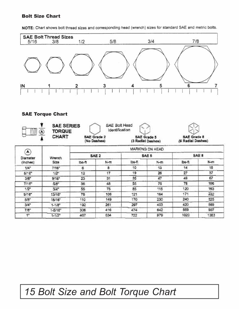
15 Bolt Size and Bolt Torque Chart
Bolt Size Chart
SAE Torque Chart

NOTES:
Notes 16

© 2010 Monroe Tufline Manufacturing, Inc. All Rights Reserved
PART NO.5TL15788


