32
OPERATOR’S MANUAL OPERATOR’S MANUAL OPX300K2 For PX-K2 and C2 series A.C. generator ends www.northern-lights.com

OPERATOR’S MANUALOPERATOR’S MANUAL
OPX300K2For PX-K2 and C2 series A.C. generator ends
www.northern-lights.com

Breathing Diesel engine exhaust and some of its constituents are known to the State of California to cause cancer, birth defects, and other reproductive harm.* Always start and operate the engine in a well-ventilated area.* If in an enclosed area, vent the exhaust to the outside.* Do not modify or tamper with the exhaust system.* Do not idle the engine except as necessary.For more information, go to www.P65warnings.ca.gov/diesel.
— CALIFORNIA —Proposition 65 Warning:
Northern Lights4420 14th Avenue NWSeattle, WA 98107Tel: (206) 789-3880Fax: (206) 782-5455
Copyright ©2018 Northern Lights, Inc.All rights reserved. Northern Lights™, andthe Northern Lights logo are trademarks ofNorthern Lights, Inc.
Printed in U.S.A.PART NO.: OPX300K2 07/18
OPX300K2 2/18
3
OPERATOR’S & PARTS MANUALPX-300K2 SERIES A.C. GENERATORS For Generator Models:PX-308K2, PX-309K2, PX-310K2, PX-312K2, PX-316K2, PX-320K2, PX-320C2, PX-325K2, PX-332K2, and PX-332C2
Read this manual thoroughly before starting your equipment.This manual contains information needed to operate your set correctly and safely.
Introduction.......................................................................4Safety.Rules......................................................................4Models.and.Serial.Numbers..............................................5Mechanical.Construction..................................................6
INITIAL INSPECTION AND COUPLING Initial.Inspection..........................................................6Coupling.with.Prime.Mover........................................6Grounding....................................................................6
PERFORMANCE AND FUNCTIONExcitation.System........................................................7.Automatic.Voltage.Regulator.(AVR)...........................7..Under.Speed.Protection...............................................7.Rotary.Rectifier.and.Surge.Suppressor........................7
CHARACTERISTICSVoltage.Regulation.......................................................8Response......................................................................8.Voltage.Stability...........................................................8.Motor.Starting..............................................................8.Short.Circuit.................................................................8.Phase.Rotation..............................................................8
STANDARD VOLTAGE SELECTION TABLE......8
OPERATION - GENERATOR SET Starting.........................................................................9.Voltage.Adjustment......................................................9Running........................................................................9Stopping.......................................................................9
OPERATION - VOLTAGE REGULATORSafety.Rules.............................................................. 10Operation.................................................................. 10Adjustment................................................................ 10.
MAINTENANCEBearing.Inspection.....................................................11Insulation.Resistance.Measurement.Method.............11Rotating.Rectifier.Assembly......................................11.Parts.Replacement.Method................................11 - 12Automatic.Voltage.Regulator.Maintenance.............. 13
SPECIFICATIONSGenerator.Specifications.................................. 14 - 15Voltage.Regulator.Specifications.............................. 16
TROUBLESHOOTING .......................................... 17
PARTS LIST...................................................... 18 - 26
WIRING DIAGRAMAVR.DST-100-2FAK............................................... 27
Table of Contents
Proprietary InformationThis.publication.is.the.property.of.Northern.Lights,.Inc.
It.may.not.be.reproduced.in.whole.or.in.part.without.the.written.permission.of.Northern.Lights,.Inc.©.Northern.Lights,.Inc..2014...All.rights.reserved...Litho.U.S.A...Publication.number.OPX-300K2.04/14

OPX300K2 2/18
4
Introduction
This.manual.describes.procedures.for.operation,maintenance,.inspection.and.adjustment..It.will.help.theoperator.realize.peak.performance.through.effective,economical.and.safe.operation.
. •. Read.this.manual.carefully.BEFORE.operating.the... generator.
. •. Study.this.manual.until.proper.operation.becomes... personal.habit.
. •. Operation,.inspection,.and.maintenance.should.be... carried.out.carefully..Safety.must.be.given.the.first... priority.
Safety Rules
. •. To.insure.years.of.trouble-free.operation,.the.. .. specified.maintenance.is.important.and.should.be... performed.
. •. Electrical equipment should always be kept clean. Oil,.dust,.moisture.and.salt.are.all.harmful... to.genera.tors.
. •. Be careful with electricity..Do.not.touch.rotating... parts.
. •. Ambient Environmental Conditions
. . a).Gas:..Do.not.use.in.an.environment.of.corrosive... . or.flammable.gas.(gasoline,.hydrogen.sulfide,... . meth.ane.gas,.etc.)
. . b).Sandy Dust:..Do.not.use.equipment.in.places... . with.excessive.sand.and.dust.
. . c).Humidity:..Do.not.use.in.very.humid.
. . . environments.for.long.periods.of.time.
. . d).Salt/Seawater:..Protect.your.generator.from.... . exposure.to.salt,.water,.and.water.vapor.
. •. Insulation Resistance and Dielectric:..When.
. . measuring.insulation.resistance.and.dielectric,.be... sure.to.disconnect.the.AVR.and.rectifier.
. •. Be.sure.that.the.regulator.is.shut.off.by.switching.the... CPR.(circuit.breaker).on.the.AVR.to.the.off.position... when.the.unit.is.run.ning.at.less.than.rated.speed,.or... when.the.unit.is.to.be.run.but.no.power.generation.is... required.
. •. Before.starting.your.generator,.be.sure.oper.ating... conditions.are.safe.
. •. Ventilation:..When.selecting.the.installation.site,.be... sure.that.the.area.is.well.ventilated.and.that.ambient... temperature.does.not.exceed.40°C..If.the.
. . temperaure.exceeds.40°C,.de-rate.the.generator..
. . output.as.per.“data.sheet”.for.operation.
. .
. •. Be.sure.to.provide.generator.with.cover.and.
. . protection.when.op.erating.outside.
. . PX-300K2 Series AC generators are based on BS 4999 part 20 and IEC34-5, IP21.

OPX300K2 2/18
5
AC Generator Data
Generator Set Data
Northern Lights, Inc., WA USAwww.northern-lights.com
Model No.Serial No.
DUTY
KW
KVA
RPM
HERTZ
PHASE
°C RISE
RULE
WIRE
INSUL
AMB°C
PF
VOLTS
VOLTS
AMPS
AMPS
Set SerialSet Model
Model and Serial Numbers
GENERATOR END MODEL NUMBERS Generator Set Model No ................ PXK Generator Model M and NL753W2 ..........................................PX-308K2 M and NL773LW2 / LW3 ..............................PX-309K2 M and NL843JW ..........................................PX-310K2 M and NL843NW2 / NW3 .............................PX-312K2 M844W2 / W3 ..............................................PX-316K2 M844LW2 / LW3 ..........................................PX-320K2 M20CRW2/ CRW3 .......................................PX-320C2 M864W / W3 ................................................PX-325K2 M944W / W3 ................................................PX-332K2 M30CW / CW3 .............................................PX-332C2 M984W .........................................................PX-332K2 M33CW ........................................................PX-332C2
SERIAL NUMBERS
. •....When.referencing.Northern.Lights.equip.ment.by.serial.
. . number,.it.is.important.to.differentiate.between.the.engine,.
. . generator.end,.and.generator.set.serial.numbers.
. •....The.engine.serial.number.is.either.on.a.metal.tag.or.stamped.
. . directly.into.the.engine.block.
. •.. The.generator.END.serial.number.is.on.a.metal.tag.attached.
. . to.the.generator.end.
. •....The.generator.SET.serial.number.is.on.a.separate.metal.tag.
. . attached.to.the.generator.end..It.may.be.a.five.by.one.inch.tag.
. . installed.directly.below.the.gen.erator.end.tag..Or,.it.may.look.
. . like.the.illustrations.below..Please.use.the.generator.SET.number
. . in.cor.respondence.or.when.ordering.parts.
Figure 1: Generator Set Serial Number Plate
OPX300K2 2/18
6
Mechanical Construction
STATORThe.stator.frame.is.fabricated.from.rolled.steel..The.round.construction.provides.rigidity.and.strength.to.resist.excessive.mechanical.shocks..The.stator.core.is.made.of.high.quality.silicon.steel.plates.coated.with.insulating.film.for.prevention.of.eddy.currents..The.core.is.positioned.along.the.internal.surface.of.the.frame..The.exciter.field.core.is.made.of.special.steel.plates.capable.of.retaining.a.high.degree.of.residual.magnetism.
BEARINGSThe.long-life.ball.bearings.are.sealed.to.prevent.grease.from.escaping.and.to.keep.dirt.out.
ROTORThe.rotor.shaft.is.made.of.high.quality.carbon.steel,.and.is.designed.and.manufactured.to.be.mechanically.durable..The.rotor.is.a.salient.revolving.field.type.with.the.main.field.core.made.from.special.steel.plates.having.superior.magnetic.characteristics..The.field.core.elements,.exciter.rotor,.rotary.rectifier.and.cooling.fan.are.integral.parts.of.the.same.shaft.
VENTILATIONCooling.is.provided.by.the.cooling.fan.of.the.rotor.through.suction.ports.and.exhausted.through.outlet.ports..Every.machine.conforms.to.the.cooling.code.ICO1.of.BS.
Initial Inspection and Coupling
INITIAL INSPECTIONIf.the.generator.is.stored.for.long.periods.of.time,.store.in.a.clean,.dry,.ventilated.area..After.extensive.stor-age.time,.check.the.resistance.of.the.coil.insulation.in.accordance.with.this.manual.(see.MAINTENANCE,.page.11).before.operation..Be.sure.there.are.no.abnor-mal.sounds.or.any.overheating.during.operation..It.is.recommended.that.standby.generators.utilize.a.space.heater.(op.tional).in.order.to.keep.the.coil.insulation.in.optimum.working.condition.
COUPLING WITH PRIME MOVER PX-300K.series.single.bearing.generators.make.centering.and.direct.coupling.easy...Coupling.bolt.size.and.torque.will.vary.according.to.the.engine.manufacturer..
GROUNDINGThe.generator.frame.should.be.electrically.grounded.to.the.base.of.the.generator.set...The.neutral.is.not.grounded.to.the.frame.unless.specified.
OPX300K2 2/18
7
Performance and Function
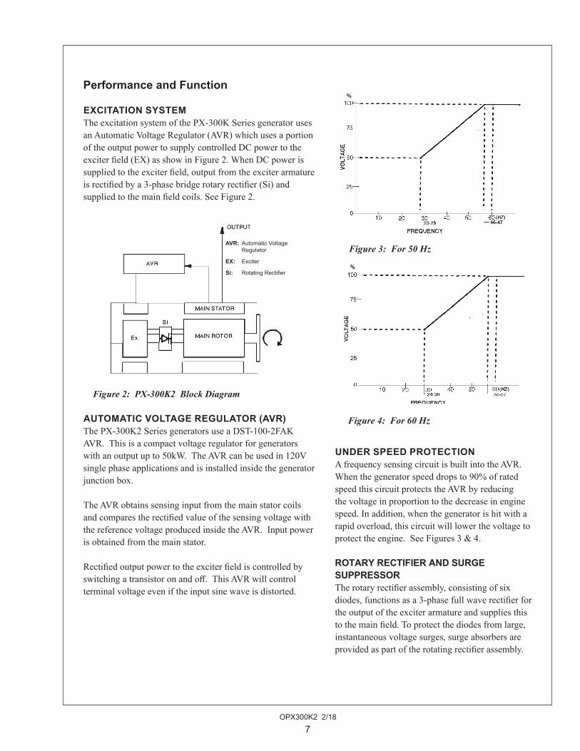
EXCITATION SYSTEMThe.excitation.system.of.the.PX-300K.Series.genera.tor.uses.an.Automatic.Voltage.Regulator.(AVR).which.uses.a.portion.of.the.output.power.to.supply.controlled.DC.power.to.the.exciter.field.(EX).as.show.in.Figure.2..When.DC.power.is.supplied.to.the.exciter.field,.output.from.the.exciter.armature.is.rectified.by.a.3-phase.bridge.rotary.rectifier.(Si).and.supplied.to.the.main.field.coils..See.Figure.2.
AUTOMATIC VOLTAGE REGULATOR (AVR)The.PX-300K2.Series.generators.use.a.DST-100-2FAK.AVR...This.is.a.compact.voltage.regulator.for.generators.with.an.output.up.to.50kW...The.AVR.can.be.used.in.120V.single.phase.applications.and.is.installed.inside.the.generator.junction.box.
The.AVR.obtains.sensing.input.from.the.main.stator.coils.and.compares.the.rectified.value.of.the.sensing.voltage.with.the.reference.voltage.produced.inside.the.AVR...Input.power.is.obtained.from.the.main.stator.
Rectified.output.power.to.the.exciter.field.is.controlled.by.switching.a.transistor.on.and.off...This.AVR.will.control.terminal.voltage.even.if.the.input.sine.wave.is.distorted.
Figure 2: PX-300K2 Block Diagram
AVR: Automatic Voltage Regulator
EX: Exciter
Si: Rotating Rectifier
Figure 4: For 60 Hz
Figure 3: For 50 Hz
UNDER SPEED PROTECTIONA.frequency.sensing.circuit.is.built.into.the.AVR..When.the.generator.speed.drops.to.90%.of.rated.speed.this.circuit.protects.the.AVR.by.reducing.the.voltage.in.proportion.to.the.decrease.in.engine.speed..In.addition,.when.the.generator.is.hit.with.a.rapid.overload,.this.circuit.will.lower.the.voltage.to.protect.the.engine...See.Figures.3.&.4.
ROTARY RECTIFIER AND SURGE SUPPRESSORThe.rotary.rectifier.assembly,.consisting.of.six.diodes,.functions.as.a.3-phase.full.wave.rectifier.for.the.output.of.the.exciter.armature.and.supplies.this.to.the.main.field..To.protect.the.diodes.from.large,.instanta.neous.voltage.surges,.surge.absorbers.are.provided.as.part.of.the.rotating.rectifier.assembly.
OPX300K2 2/18
8
Characteristics
VOLTAGE REGULATIONGenerator.terminal.voltage.regulation.is.within.±1%.of.the.rated.voltage.in.lagging.power.factor..1.0.to.0.8,.when.the.load.is.varied.gradually.from.no.load.to.full.load..This.value.includes.the.temperature.drift.and.rotating.variation.
RESPONSEAfter.supplying.a.load.instantaneously,.the.generator.voltage.should.be.restored.to.the.steady.condition.in.accordance.with.BS4999.Part.40,.grade.VR2.11.to.VR2.23.
VOLTAGE STABILITYIn.constant.load.and.engine.speed,.voltage.stability.remains.0.25%.of.the.rated.voltage.
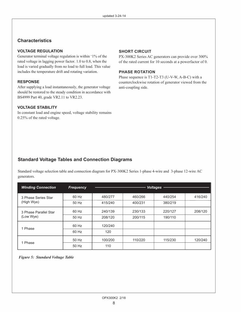
Winding Connection Frequency Voltages
3 Phase Series Star 60 Hz 480/277 460/266 440/254 416/240 (High Wye) 50 Hz 415/240 400/231 380/219
3 Phase Parallel Star 60 Hz 240/139 230/133 220/127 208/120 (Low Wye) 50 Hz 208/120 200/115 190/110
1 Phase
60 Hz 120/240 60 Hz 120
1 Phase
50 Hz 100/200 110/220 115/230 120/240 50 Hz 110
SHORT CIRCUITPX-300K2.Series.AC.generators.can.provide.over.300%.of.the.rated.current.for.10.seconds.at.a.powerfactor.of.0.
PHASE ROTATIONPhase.sequence.is.T1-T2-T3.(U-V-W,.A-B-C).with.a.counterclockwise.rotation.of.generator.viewed.from.theanti-coupling.side.
Figure 5: Standard Voltage Table
Standard Voltage Tables and Connection Diagrams
Standard.voltage.selection.table.and.connection.diagram.for.PX-300K2.Series.1-phase.4-wire.and..3-phase.12-wire.ACgenerators...
updated 3-24-14

OPX300K2 2/18
9
Operation – Generator Set
STARTINGBefore.starting.generator,.check.the.following:. 1.. Make.sure.that.the.wiring.is.correct.. 2.. Be.sure.that.nothing.is.blocking.the.air.inlet/.outlet.. 3.. Make.sure.that.the.inside.of.the.generator.is.clean.. 4.. Be.sure.the.main.line.circuit.breaker.is.switched... OFF.
After.checking.each.of.the.above,.start.the.generator.in.thefollowing.procedure:. 1.. Start.engine.in.accordance.with.instructions.in.the... Operator’s.Manual..Be.sure.there.is.no.abnormal... sound.or.vibration.
. 2.. The.voltage.will.rise.due.to.the.increase.in.generator... speed..After.making.sure.that.each.interphase.voltage... is.balanced,.set.the.voltage.and.frequency.to.the.rated... level..Be.sure.the.CPR.switch.is.“ON”..The.voltage... will.not.rise.with.CPR.“OFF”.
. 3.. After.running.the.generator.without.load,.switch.the... circuit.breaker.ON.to.start.the.load.operation.
VOLTAGE ADJUSTMENT. The.generator.has.been.adjusted.to.obtain.optimum.. voltage.at.the.factory..If.the.voltage.is.different,.adjust.the.voltage.with.the.Voltage.Adjust.provided.on.the.AVR..
RUNNINGCheck.the.following.while.operating.the.generator:. 1.. Abnormal.vibration.and/or.sound. 2.. Load. 3.. Environment:. Keep.the.air.inlet/outlet.clean.and.clear.for.optimum. cooling..Insufficient.cooling.causes.over.heating.of.the. generator.
Note:.When a 3-phase generator is used at single phase load, each phase current should be balanced and should not exceed 50% of the rated current. In addition,
allowable unbalanced load is listed on the Data Sheet.
STOPPINGAfter.putting.the.running.generator.in.a.no-load.conditionby.removing.the.generator.load,.stop.the.engine.inaccordance.with.the.Engine.Manual.
OPX300K2 2/18
10
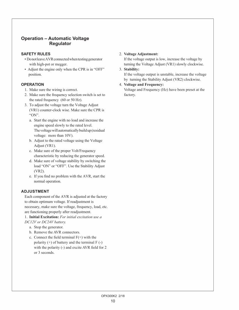
Operation – Automatic Voltage Regulator
SAFETY RULES. •..Do.not.leave.AVR.connected.when.testing.generator.... with.high-pot.or.megger.
. •..Adjust.the.engine.only.when.the.CPR.is.in.“OFF”.......position.
OPERATION. 1.. Make.sure.the.wiring.is.correct.. 2.. Make.sure.the.frequency.selection.switch.is.set.to... the.rated.frequency..(60.or.50.Hz).
. 3.. To.adjust.the.voltage.turn.the.Voltage.Adjust.. .. (VR1).counter-clock.wise..Make.sure.the.CPR.is.... “ON”.
. . a.. Start.the.engine.with.no.load.and.increase.the.... . engine.speed.slowly.to.the.rated.level...
. . . The.voltage.will.automatically.build.up.(residual... . voltage:..more.than.10V).
. . b.. Adjust.to.the.rated.voltage.using.the.Voltage.. .. . Adjust.(VR1).
. . c.. Make.sure.of.the.proper.Volt/Frequency.. .. . characteristic.by.reducing.the.generator.speed.
. . d.. Make.sure.of.voltage.stability.by.switching.the... . load.“ON”.or.“OFF”..Use.the.Stability.Adjust... . (VR2).
. . e.. If.you.find.no.problem.with.the.AVR,.start.the... . normal.operation.
ADJUSTMENT. Each.component.of.the.AVR.is.adjusted.at.the.factory.to.obtain.optimum.voltage..If.readjustment.is.
. necessary,.make.sure.the.voltage,.frequency,.load,.etc..are.functioning.properly.after.readjustment.
. 1.. Initial Excitation:.For initial excitation use a DC12V or DC24V battery.
. . a.. Stop.the.generator.
. . b.. Remove.the.AVR.connectors.
. . c.. Connect.the.field.terminal.F(+).with.the.. .. . polarity.(+).of.battery.and.the.terminal.F.(-).. .. . with.the.polarity.(-).and.excite.AVR.field.for.2... . or.3.seconds.
. 2..Voltage Adjustment:
. . If.the.voltage.output.is.low,.increase.the.voltage.by... turning.the.Voltage.Adjust.(VR1).slowly.clockwise.
. 3.. Stability:
. . If.the.voltage.output.is.unstable,.increase.the.voltage... by..turning.the.Stability.Adjust.(VR2).clockwise.
. 4..Voltage and Frequency:
. . Voltage.and.Frequency.(Hz).have.been.preset.at.the.. factory.

OPX300K2 2/18
11
Maintenance
BEARING INSPECTIONFor.bearing.inspection,.make.sure.that.there.is.no.abnormal.sound.during.normal.running.and.no.over-heating...Greasing.is.not.necessary.for.generators.using.the.double.seal.type.ball.bearings,.but.these.will.need.to.be.replaced.after.every.10,000.hours.of.operation.(see.PARTS REPLACEMENT METHOD).
INSULATION RESISTANCE MEASUREMENT If.the.generator.has.not.been.used.for.a.long.time,.check.the.insulation.resistance.of.each.lead.wire.at.500V.with.a.megger..It.is.usually.enough.to.check.only.the.stator.winding...In.order.to.prevent.damage.to.the.AVR,.disconnect.it...If.the.measured.insulation.resis.tance.value.is.above.2.M.ohms,.there.is.no.problem,.but.if.it.is.lower.than.that,.check.to.see.if.the.inside.of.the.generator.is.wet.or.dirty...If.dust.has.accumulated,.blow.it.out.with.dry.compressed.air...Wipe.off.oil.stains.with.a.cloth...If.the.generator.is.damp,.dry.it.and.re-check.
ROTATING RECTIFIER ASSEMBLY The.rotating.rectifier.assembly.needs.little.attention...Clean.off.dust.and.oil.stains.periodically...In.the.unlikely.event.that.it.becomes.necessary.to.replace.the.diode.ele-ments.and.surge.absorber.elements...Refer.to.PARTS REPLACEMENT METHOD.
PARTS REPLACEMENT METHOD. 1.. Bearing.Replacement:. . a.. In.order.to.replace.the.bearing,.first.remove.the... . bearing.holder.housing.on.the.end.of.the.
. . . generator...Loosen.and.remove.the.four.housing... . bolts...Remove.the.bearing.holder.gently.since... . there.is.a.risk.that.the.rotor.could.fall.and.damage... . the.exciter.rotor.or.the.exciter.stator..
Figure 6. Pilot Length
. . b.. Using.a.bearing.puller,.extract.bearing.from.. .. . shaft.
. . c.. When.installing.a.new.bearing,.place.a.steel.pipe... . .on.the.inner.race.surface,.and.fit.the.bearing.by... . .tapping.it.lightly.with.a.hammer.
Figure 7. Bearing Puller
Note:.Absolutely.do.not.apply.pressure.to.outer.race... ..... ....of.the.bearing.during.insertion.
OPX300K2 2/18
12
Maintenance
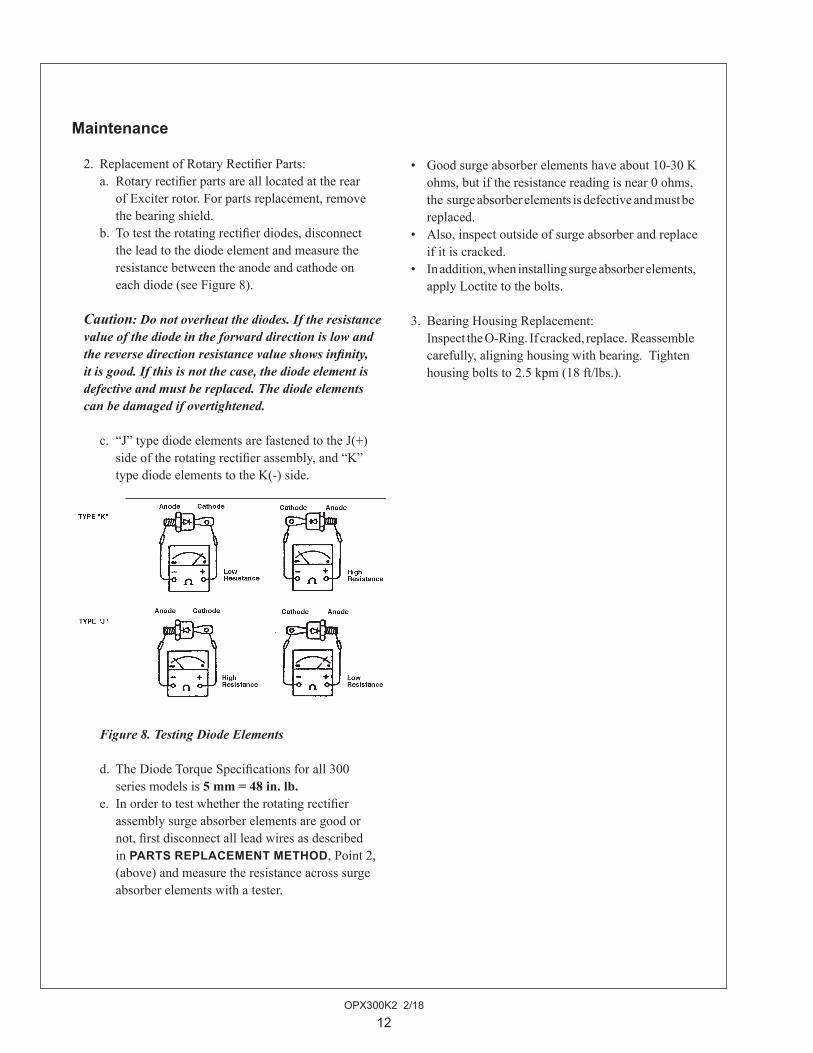
. 2.. Replacement.of.Rotary.Rectifier.Parts:
. . a.. Rotary.rectifier.parts.are.all.located.at.the.rear... . of.Exciter.rotor..For.parts.replacement,.remove... . the.bearing.shield.
. . b.. To.test.the.rotating.rectifier.diodes,.disconnect... . the.lead.to.the.diode.element.and.measure.the... . resistance.between.the.anode.and.cathode.on.... . each.diode.(see.Figure.8).
Caution: Do not overheat the diodes. If the resist ance value of the diode in the forward direction is low and the reverse direction resistance value shows infinity, it is good. If this is not the case, the diode element is defective and must be replaced. The diode elements can be damaged if overtightened.
. . c.. “J”.type.diode.elements.are.fastened.to.the.J(+)... . side.of.the.rotating.rectifier.assembly,.and.“K”... . type.diode.elements.to.the.K(-).side.
Figure 8. Testing Diode Elements
. . d.. The.Diode.Torque.Specifications.for.all.300.. .. . series.models.is.5 mm = 48 in. lb.
. . e.. In.order.to.test.whether.the.rotating.rectifier.. .. . assembly.surge.absorber.elements.are.good.or... . not,.first.disconnect.all.lead.wires.as.described... . in.PARTS REPLACEMENT METHOD,.Point.2,
. . . (above).and.measure.the.resistance.across.surge.
. . . absorber.elements.with.a.tester..
. •. Good.surge.absorber.elements.have.about.10-30.K... ohms,.but.if.the.resistance.reading.is.near.0.ohms,... the..surge.absorber.elements.is.defective.and.must.be... replaced..
. •. Also,.inspect.outside.of.surge.absorber.and.replace... if.it.is.cracked..
. •. In.addition,.when.installing.surge.absorber.elements,... apply.Loctite.to.the.bolts.
. 3.. Bearing.Housing.Replacement:
. . Inspect.the.O-Ring..If.cracked,.replace...Reassemble... carefully,.aligning.housing.with.bearing...Tighten... housing.bolts.to.2.5.kpm.(18.ft/lbs.).

OPX300K2 2/18
13
. 4.. Rotating.Rectifier.Assembly.Detailed.Structure:
Figure 9. Rotating Rectifier.
Maintenance – Automatic Voltage Regulator
. 1.. Keep.the.AVR.clean.at.all.times...Make.sure.no.dust.or.moisture.accumulates... on.the.AVR.
. 2.. Inspect.periodically.making.sure.that.wiring.connections.are.not.loose.

OPX300K2 2/18
14
Generator Specifications: Taiyo Winding Resistances
All ratings in Ohms @ 20° C
Model Number 1 Phase 3 Phase
MAIN PX-308K2 0.588.ohms. 0.656.ohmsSTATOR:. PX-309K2 0.588.ohms. 0.656.ohms PX-310K2. 0.527.ohms. 0.436.ohms PX-312K2. 0.298.ohms. 0.315.ohms PX-316K2. 0.234.ohms. 0.198.ohms PX-320K2 & PX-320C2. 0.195.ohms. 0.136.ohms. PX-325K2 0.115.ohms. 0.0950.ohms. PX-332K2 & PX-332C2 0.094.ohms. 0.0817.ohms. Model Number 1 Phase 3 Phase
MAIN PX-308K2 .1.84.ohms. 1.84.ohmsROTOR:. PX-309K2 .1.84.ohms. 1.84.ohms PX-310K2. .1.95.ohms. 1.95.ohms PX-312K2. .2.10.ohms. 2.10.ohms PX-316K2. .2.40.ohms. 2.40.ohms PX-320K2 & PX-320C2. .2.77.ohms. 2.77.ohms. PX-325K2 .3.60.ohms. 3.60.ohms. PX-332K2 & PX-332C2 3.91.ohms. 3.91.ohms Model Number 1 Phase 3 Phase
EXCITER PX-308K2 & PX-309K2 .15.8.ohms. 15.8.ohmsSTATOR: PX-310K2. .15.8.ohms. 15.8.ohms PX-312K2. .15.8.ohms. 15.8.ohms PX-316K2. .17.0.ohms. 17.0.ohms PX-320K2 & PX-320C2. .17.0.ohms. 17.0.ohms. PX-325K2. .17.0.ohms. 17.0.ohms. PX-332K2 & PX-332C2 .19.2.ohms. 19.2.ohms.

OPX300K2 2/18
15
Model Number 1 Phase 3 Phase
EXCITER PX-308K2 & PX-309K2 0.510.ohms. 0.510.ohmsROTOR: PX-310K2. 0.510.ohms. 0.510.ohms PX-312K2. 0.510.ohms. 0.510.ohms PX-316K2. 0.530.ohms. 0.530.ohms PX-320K2 & PX-320C2. 0.530.ohms. 0.530.ohms. PX-325K2. 0.530.ohms. 0.530.ohms. PX-332K2 & PX-332C2. 0.580.ohms. 0.580.ohms
Model Number 1 Phase 3 Phase
FULL LOAD PX-308K2 & PX-309K2EXCITATION 50.Hz/.220.volts. 31.8.volts. 23.0.voltsVOLTAGE:. 60.Hz/.240.volts. 37.5.volts. 27.1.volts. . PX-310K2 50.Hz/.220.volts. 36.4.volts. 26.2.volts. 60.Hz/.240.volts. .41.7.volts. 28.9.volts PX-312K2 50.Hz/.220.volts. 45.5.volts. 32.8.volts.. 60.Hz/.240.volts. .50.0.volts. 36.1.volts PX-316K2 50.Hz/.220.volts. 54.5.volts. 39.4.volts. 60.Hz/.240.volts. .66.7.volts. 48.1.volts PX-320K2 & PX-320C2 50.Hz/.220.volts. 72.7.volts. 52.5.volts. 60.Hz/.240.volts. .83.3.volts. 60.1.volts. PX-325K2 50.Hz/.220.volts. 90.9.volts. 52.5.volts. 60.Hz/.240.volts. .104.2.volts. 60.1.volts. PX-332K2 & PX-332C2 50.Hz/.220.volts. 118.2.volts. 68.2.volts. 60.Hz/.240.volts. .137.5.volts. 79.4.volts.
AUXILIARY WINDING: PX-309K2 5.87.V 2.89.V PX-310K2 6.31.V 2.45.V PX-312K2 5.31.V 2.37.V PX-316K2 4.41.V 1.58.V PX-320K2 & PX-320C2 3.49.V 1.57.V PX-325K2 3.29.V 1.67.V PX-332K2 & PX-332C2 3.09.V 1.49.V. . . .. .
Generator Specifications: Taiyo Winding Resistances
All ratings in Ohms @ 20° C
OPX300K2 2/18
16
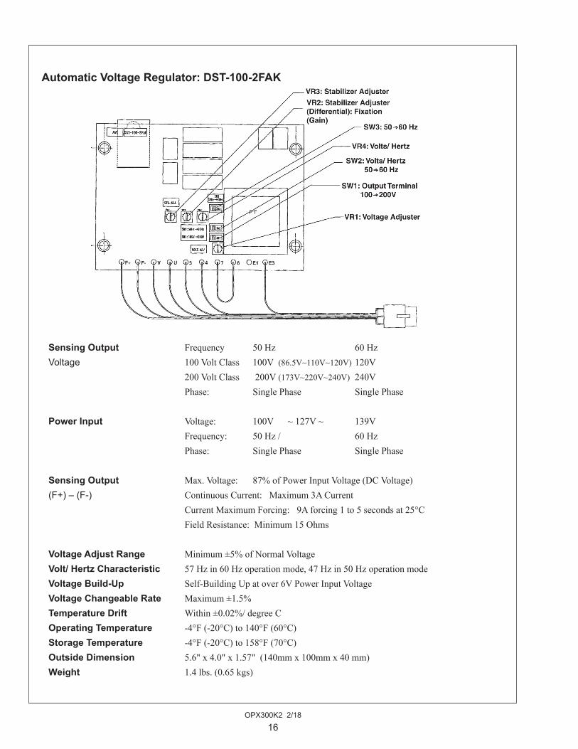
Sensing Output. Frequency. 50.Hz. . . 60.Hz.Voltage. 100.Volt.Class. 100V..(86.5V~110V~120V).120V. 200.Volt.Class. .200V.(173V~220V~240V). 240V. Phase:. Single.Phase. . Single.Phase
Power Input. Voltage:. 100V......~.127V.~. 139V. Frequency:. 50.Hz./. . . 60.Hz. Phase:. Single.Phase. . Single.Phase
Sensing Output. Max..Voltage:. 87%.of.Power.Input.Voltage.(DC.Voltage)(F+) – (F-). Continuous.Current:...Maximum.3A.Current. Current.Maximum.Forcing:...9A.forcing.1.to.5.seconds.at.25°C. Field.Resistance:..Minimum.15.Ohms.Voltage Adjust Range. Minimum.±5%.of.Normal.VoltageVolt/ Hertz Characteristic. 57.Hz.in.60.Hz.operation.mode,.47.Hz.in.50.Hz.operation.modeVoltage Build-Up. Self-Building.Up.at.over.6V.Power.Input.VoltageVoltage Changeable Rate. Maximum.±1.5%Temperature Drift. Within.±0.02%/.degree.COperating Temperature. -4°F.(-20°C).to.140°F.(60°C)Storage Temperature. -4°F.(-20°C).to.158°F.(70°C)Outside Dimension. 5.6".x.4.0".x.1.57"..(140mm.x.100mm.x.40.mm)Weight. 1.4.lbs..(0.65.kgs)
Automatic Voltage Regulator: DST-100-2FAK

OPX300K2 2/18
17
Trouble Shooting
PROBLEM POSSIBLE CAUSE RECOMMENDATION(S)
Only a FEW VOLTS. Loss.of.residual.magnetism.of.the.exiter.field. •. Flash.field.of output. Disconnection.or.short.circuit.of.windings. •. Check.the.insulation.of.all.windings. . . . and.check.the.resistance.value.
. Defective.AVR. •. Check.the.AVR.
. Defective.rotating.rectifier.assembly. •. Replace.diode.elements.
Voltage is LOW. Incorrect.wiring.(GEN,.AVR). •. Check.the.winding.connection.
. Low.speed. •. Check.the.engine.
. Overload. •. Reduce.the.load.
. Defective.AVR. •. Check.the.AVR.
Voltage DIPS. Starting.of.big.motor.or.spot.welding.machine. •. About.15%.voltage.dip.is.no.problem.when on load. Defective.diode.on.rotating.rectifier. •. Change.diode.. [F(+).–.F(-).terminal.voltage.will.show.a. very.high.value.when.a.diode.is.defective]Voltage is HIGH.. Incorrect.wiring.(GEN,.AVR). •. Check.the.AVR.
. Too.high.speed. •. Check.the.engine.
. Defective.AVR. •. Check.the.AVR.
Voltage FLUCTUATES. Wiring.leads.are.loose. •. Tighten.leads.
. Irregular.speed.of.engine. •. Check.the.engine.
. Poor.AVR.adjustment. •. Check.the.AVR.
. External.noise. •. Check.the.filter.
Abnormal SOUND. Foundation.uneven. •. Check.ground.level.or VIBRATION. Poor.mounting. •. Check.the.mounting.section.
. Misaligned.coupling. •. Check.the.coupling.section.
. Defective.bearing. •. Replace.the.bearing.
OPX300K2 2/18
18
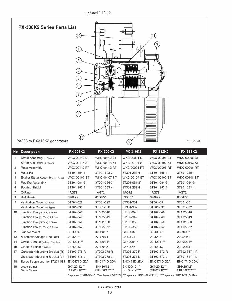
No Description PX-308K2 PX-309K2 PX-310K2 PX-312K2 PX-316K2 1 Stator Assembly (1-Phase) WKC-00112-ST WKC-00112-ST WKC-00094-ST WKC-00095-ST WKC-00096-ST Stator Assembly (3-Phase) WKC-00113-ST WKC-00113-ST WKC-00101-ST WKC-00102-ST WKC-00103-ST 2 Rotor Assembly WKC-00112-RT WKC-00112-RT WKC-00094-RT WKC-00095-RT WKC-00096-RT 3 Rotor Fan 3T301-254-4 3T301-593-2 3T301-255-4 3T301-255-4 3T301-255-4 4 Excitor Stator Assembly (1-Phase) WKC-00107-ST WKC-00107-ST WKC-00107-ST WKC-00107-ST WKC-00108-ST 5 Rectifier Assembly 3T201-084-3* 3T201-084-3* 3T201-084-3* 3T201-084-3* 3T201-084-3* 6 Bearing Shield 3T301-253-4 3T301-253-4 3T301-253-4 3T301-253-4 3T301-253-4 7 O-Ring 1AG72 1AG72 1AG72 1AG72 1AG72 8 Ball Bearing 6306ZZ 6306ZZ 6306ZZ 6306ZZ 6306ZZ 9 Ventilation Cover (M Type) 3T301-329 3T301-329 3T301-331 3T301-331 3T301-331 Ventilation Cover (NL Type) 3T301-330 3T301-330 3T301-332 3T301-332 3T301-332 10 Junction Box (M Type) 1 Phase 3T102-346 3T102-346 3T102-346 3T102-346 3T102-346 Junction Box (NL Type) 1 Phase 3T102-349 3T102-349 3T102-349 3T102-349 3T102-349 Junction Box (M Type) 3 Phase 3T102-350 3T102-350 3T102-350 3T102-350 3T102-350 Junction Box (NL Type) 3 Phase 3T102-352 3T102-352 3T102-352 3T102-352 3T102-352 11 Rubber Mount 33-40007 33-40007 33-40007 33-40007 33-40007 13 Automatic Voltage Regulator 22-42071 22-42071 22-42071 22-42071 22-42071 14 Circuit Breaker (Voltage Regulator) 22-42084** 22-42084** 22-42084** 22-42084** 22-42084** 15 Circuit Breaker (Engine) 22-42043 22-42043 22-42043 22-42043 22-42043 17 Generator Mounting Bracket (R) 3T303-278 R 3T303-278 R 3T303-372 R 3T303-372 R 3T302-857-1 R Generator Mounting Bracket (L) 3T303-278 L 3T303-278 L 3T303-372 L 3T303-372 L 3T301-857-1 L 18 Surge Suppressor for 3T201-084 ENC471D-2DA ENC471D-2DA ENC471D-2DA ENC471D-2DA ENC471D-2DA 19 Diode Element SKN26/12*** SKN26/12*** SKN26/12*** SKN26/12*** SKN26/12*** Diode Element SKR26/12**** SKR26/12**** SKR26/12**** SKR26/12**** SKR26/12**** *replaces 3T201-084-2 **replaces 22-42077 ***replaces SIDO1-09 (74113) ****replaces ERD51-09 (74114)
PX308 to PX316K2 generators 3T102-344
PX-300K2 Series Parts List
updated.9-13-10

OPX300K2 2/18
19
No Description PX-320K2 PX-325K2 PX-332K2 1 Stator Assembly (1-Phase) WKC-00097-ST WKC-00098-ST WKC-00099-ST Stator Assembly (3-Phase) WKC-00104-ST WKC-00105-ST WKC-00106-ST 2 Rotor Assembly WKC-00097-RT WKC-00098-RT WKC-00099-RT 3 Rotor Fan 3T301-255-4 3T301-255-4 3T301-553 4 Excitor Stator Assembly (1-Phase) WKC-00108-ST WKC-00108-ST WKC-00109-ST 5 Rectifier Assembly 3T201-084-3* 3T201-084-3* 3T201-084-3* *replaces 3T201-084
6 Bearing Shield 3T301-253-4 3T301-253-4 3T301-349-2 7 O-Ring 1AG72 1AG72 1BG90 8 Ball Bearing 6306ZZ 6306ZZ 6308ZZ 9 Ventilation Cover (M Type) 3T301-331 3T301-331 3T301-389 Ventilation Cover (NL Type) 3T301-332 3T301-389 10 Junction Box (M Type) 1 Phase 3T102-346 3T102-347 3T102-348 Junction Box (NL Type) 1 Phase 3T102-349 3T102-348 Junction Box (M Type) 3 Phase 3T102-350 3T102-350 3T102-351 Junction Box (NL Type) 3 Phase 3T102-352 3T102-351 11 Rubber Mount 33-40007 33-40007 33-40007 13 Automatic Voltage Regulator 22-42071 22-42071 22-42071 14 Circuit Breaker (Voltage Regulator) 22-42084** 22-42084** 22-42084** **replaces 22-42077
15 Circuit Breaker (Engine) 22-42043 22-42043 22-42043 17 Generator Mounting Bracket (R) 3T302-857-1 R 3T302-857-1 R 23-65413 Generator Mounting Bracket (L) 3T302-857-1 L 3T302-857-1 L 23-65413 Generator Mtg. Bracket (R&L) 23-61201 M944 & M30CW 18 Surge Suppressor for 3T201-084 ENC471D-2DA ENC471D-2DA ENC471D-2DA 19 Diode Element SKN26/12*** SKN26/12*** SKN26/12*** ***replaces SID01-09 (74113) Diode Element SKR26/12**** SKR26/12**** SKR26/12**** ****replaces ERD51-09 (74114)
PX320 to PX325K2 generatorsPX332K2 generators
3T102-344
}M984 & M33C
PX-300K2 Series Parts List
updated.9-13-10
OPX300K2 2/18
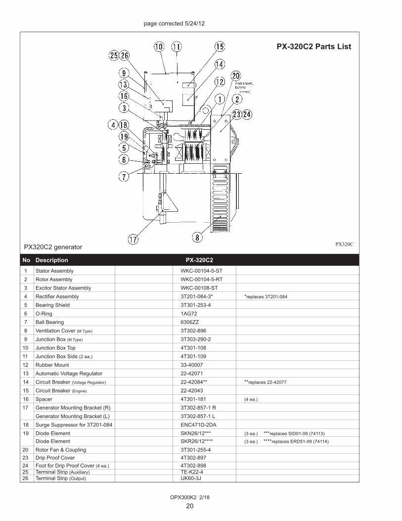
20
page corrected 5/24/12
No Description PX-320C2 1 Stator Assembly WKC-00104-5-ST 2 Rotor Assembly WKC-00104-5-RT 3 Excitor Stator Assembly WKC-00108-ST 4 Rectifier Assembly 3T201-084-3* *replaces 3T201-084
5 Bearing Shield 3T301-253-4 6 O-Ring 1AG72 7 Ball Bearing 6306ZZ 8 Ventilation Cover (M Type) 3T302-896 9 Junction Box (M Type) 3T303-290-2 10 Junction Box Top 4T301-10811 Junction Box Side (2 ea.) 4T301-109 12 Rubber Mount 33-40007 13 Automatic Voltage Regulator 22-42071 14 Circuit Breaker (Voltage Regulator) 22-42084** **replaces 22-42077 15 Circuit Breaker (Engine) 22-42043 16 Spacer 4T301-181 (4 ea.) 17 Generator Mounting Bracket (R) 3T302-857-1 R Generator Mounting Bracket (L) 3T302-857-1 L 18 Surge Suppressor for 3T201-084 ENC471D-2DA 19 Diode Element SKN26/12*** (3 ea.) ***replaces SID01-09 (74113)
Diode Element SKR26/12**** (3 ea.) ****replaces ERD51-09 (74114)
20 Rotor Fan & Coupling 3T301-255-423 Drip Proof Cover 4T302-897 24 Foot for Drip Proof Cover (4 ea.) 4T302-898 25 Terminal Strip (Auxiliary) TE-K22-4 26 Terminal Strip (Output) UK60-3J
PX320C2 generator PX320C
PX-320C2 Parts List
OPX300K2 2/18
21
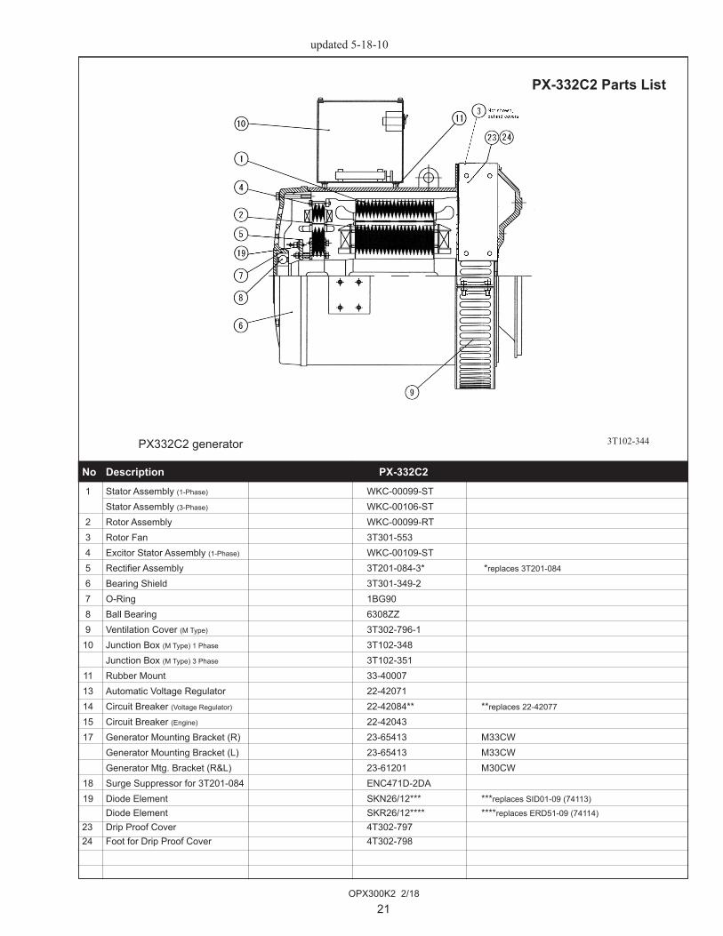
PX332C2 generator 3T102-344
PX-332C2 Parts List
No Description PX-332C2 1 Stator Assembly (1-Phase) WKC-00099-ST Stator Assembly (3-Phase) WKC-00106-ST 2 Rotor Assembly WKC-00099-RT 3 Rotor Fan 3T301-553 4 Excitor Stator Assembly (1-Phase) WKC-00109-ST 5 Rectifier Assembly 3T201-084-3* *replaces 3T201-084
6 Bearing Shield 3T301-349-2 7 O-Ring 1BG90 8 Ball Bearing 6308ZZ 9 Ventilation Cover (M Type) 3T302-796-1 10 Junction Box (M Type) 1 Phase 3T102-348 Junction Box (M Type) 3 Phase 3T102-351 11 Rubber Mount 33-40007 13 Automatic Voltage Regulator 22-42071 14 Circuit Breaker (Voltage Regulator) 22-42084** **replaces 22-42077 15 Circuit Breaker (Engine) 22-42043 17 Generator Mounting Bracket (R) 23-65413 M33CW Generator Mounting Bracket (L) 23-65413 M33CW Generator Mtg. Bracket (R&L) 23-61201 M30CW 18 Surge Suppressor for 3T201-084 ENC471D-2DA 19 Diode Element SKN26/12*** ***replaces SID01-09 (74113)
Diode Element SKR26/12**** ****replaces ERD51-09 (74114)
23 Drip Proof Cover 4T302-79724 Foot for Drip Proof Cover 4T302-798
updated.5-18-10

OPX300K2 2/18
22
PX-308K2 to PX-320K2 Junction Box, Single Phase, Marine
Key Description Part Number 1 Grommet NG-79-R 2 DC Circuit Breaker 22-42043 * Snap-in - use with #13 Circuit Breaker 15A 22-40674 * 2 Screw Mtg - use with 3 Terminal 22-42036 4 Plug 3191-09P 5 Automatic Voltage Regulator (DST-100-2FAK) 22-42071 7 AC Circuit Breaker 2 Amp x 3 Amp 2 Pole 22-42084* *replaces 22-42077 8 Rubber Tube 9 Rubber Mount 33-40007 (4 ea.) 10 Bracket, Junction Box Mtg. - Right 4T301-309 11 Spacer 4T301-181 (2 ea.) 12 Bracket, Junction Box Mtg. - Left 4T301-310 13 Junction Box 3T303-289-2* (2 ea.) *replaces 3T303-289-1
14 Top Panel 4T301-108 15 Side Panel 4T301-109 (2 ea.)
3T102-346
revised 4-7-14
Circuit Breaker

OPX300K2 2/18
23
PX-325K2Junction Box, Single Phase, Marine
Key Description Part Number 1 Grommet NG-79-R 2 DC Circuit Breaker 15 Amp 22-42043 3 Terminal UKT100-4J 4 Automatic Voltage Regulator (DST-100-2FAK) 22-42071 5 Plug 3191-09P 7 AC Circuit Breaker 2 Amp x 3 Amp 2 Pole 22-42084* *replaces 22-42077 8 Rubber Tube 9 Rubber Mount 33-40007 (4 ea.) 10 Bracket, Junction Box - Right 4T301-309 11 Spacer 4T301-181 (2 ea.) 12 Bracket, Junction Box Mtg. - Left 4T301-310 13 Junction Box 3T303-292-2 ** **formerly #3T303-292-1
14 Top Panel 4T301-108 15 Side Panel 4T301-109 (2 ea.)
3T102-347
revised 4-7-14
Circuit Breaker

OPX300K2 2/18
24
PX-332K2 Junction Box, Single Phase, Marine
Key Description Part Number 1 Junction Box 3T303-291-3* *replaces 3T303-291-1 2 Bracket, Junction Box Mounting 3T302-782-1 (2 ea.) 3 Top Panel 4T302-144 4 Side Panel 4T302-859 (2 ea.) 5 Grommet 4M911-018 6 Plug 3191-09P 7 Grommet NG-79-R
9 Terminal Strip 22-45413 11 DC Circuit Breaker 15 Amp 22-42043 12 AC Circuit Breaker 2 Amp x 3 Amp 2 Pole 22-42084** **replaces 22-42077
13 Automatic Voltage Regulator 22-42071 14 Rubber Mount 33-40007
3T102-348
revised 4-7-14
Circuit Breaker

OPX300K2 2/18
25
PX-308K2 to PX-325K2Junction Box, Three Phase, Marine
Key Description Part Number 1 Grommet NG-79-R 2 DC Circuit Breaker 15 Amp 22-42043 3 Terminal Strip TE-K22-4 4 Terminal UK60-3J *former # UKT60-3J 5 Automatic Voltage Regulator (DST-100-2FAK) 22-42071 7 AC Circuit Breaker 2 Amp x 3 Amp 2 Pole 22-42084* *replaces 22-42077 8 Rubber Tube 9 Rubber Mount 33-40007 (4 ea.) 10 Bracket, Junction Box 4T301-309 11 Plug 3191-09P 12 Spacer 4T301-181 (4 ea.) 13 Bracket, Junction Box Mtg. - Left 4T301-310 Bracket, Junction Box Mtg. - Right 4T301-309 14 Junction Box 3T303-290-2** **replaces 3T303-290-1
15 Top Panel 4T301-108 16 Side Panel 4T301-109 (2 ea.)
3T102-350
revised 4-7-14
Circuit Breaker
OPX300K2 2/18
26
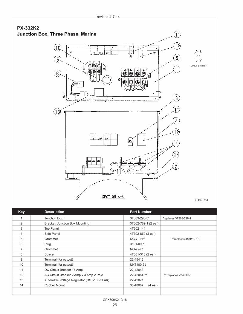
PX-332K2Junction Box, Three Phase, Marine
Key Description Part Number 1 Junction Box 3T303-298-3* *replaces 3T303-298-1 2 Bracket, Junction Box Mounting 3T302-782-1 (2 ea.) 3 Top Panel 4T302-144 4 Side Panel 4T302-859 (2 ea.) 5 Grommet NG-79-R** **replaces 4M911-018
6 Plug 3191-09P 7 Grommet NG-79-R 8 Spacer 4T301-310 (2 ea.) 9 Terminal (for output) 22-45413 10 Terminal (for output) UKT100-3J 11 DC Circuit Breaker 15 Amp 22-42043 12 AC Circuit Breaker 2 Amp x 3 Amp 2 Pole 22-42084*** ***replaces 22-42077
13 Automatic Voltage Regulator (DST-100-2FAK) 22-42071 14 Rubber Mount 33-40007 (4 ea.)
3T102-351
revised 4-7-14
Circuit Breaker
OPX300K2 2/18
27
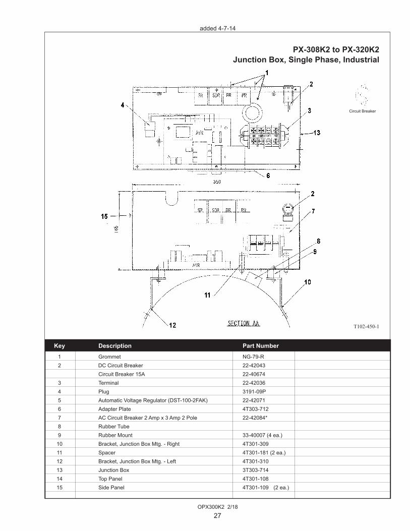
added 4-7-14
PX-308K2 to PX-320K2 Junction Box, Single Phase, Industrial
Key Description Part Number 1 Grommet NG-79-R 2 DC Circuit Breaker 22-42043 Circuit Breaker 15A 22-40674 3 Terminal 22-42036 4 Plug 3191-09P 5 Automatic Voltage Regulator (DST-100-2FAK) 22-42071 6 Adapter Plate 4T303-712 7 AC Circuit Breaker 2 Amp x 3 Amp 2 Pole 22-42084* 8 Rubber Tube 9 Rubber Mount 33-40007 (4 ea.) 10 Bracket, Junction Box Mtg. - Right 4T301-309 11 Spacer 4T301-181 (2 ea.) 12 Bracket, Junction Box Mtg. - Left 4T301-310 13 Junction Box 3T303-714 14 Top Panel 4T301-108 15 Side Panel 4T301-109 (2 ea.)
3T102-450-1
Circuit Breaker

OPX300K2 2/18
28
Key Description Part Number 1 Grommet NG-79-R 2 DC Circuit Breaker 15 Amp 22-42043 3 Terminal Strip TE-K22-4 4 Terminal UK60-3J 5 Automatic Voltage Regulator (DST-100-2FAK) 22-42071 7 AC Circuit Breaker 2 Amp x 3 Amp 2 Pole 22-42084* 8 Rubber Tube 9 Rubber Mount 33-40007 (4 ea.) 10 Bracket, Junction Box 4T301-309 11 Plug 3191-09P 12 Spacer 4T301-181 (4 ea.) 13 Bracket, Junction Box Mtg. - Left 4T301-310 Bracket, Junction Box Mtg. - Right 4T301-309 14 Junction Box 3T303-716-1 15 Top Panel 4T301-108 16 Side Panel 4T301-109 (2 ea.)
3T102-451-1
added 4-7-14
Circuit Breaker
PX-308K2 to PX-325K2Junction Box, Three Phase, Industrial

OPX300K2 2/18
29
Key Description Part Number 1 Grommet NG-79-R 2 DC Circuit Breaker 22-42043 DC Circuit Breaker 22-40674 3 Terminal 22-42036 4 Plug 3191-09P 5 Automatic Voltage Regulator (DST-100-2FAK) 22-42071 6 Adapter Plate 4T303-712 7 AC Circuit Breaker 2 Amp x 3 Amp 2 Pole 22-42084* 8 Rubber Tube 9 Rubber Mount 33-40007 (4 ea.) 10 Bracket, Junction Box Mtg. - Right 4T301-309 11 Spacer 4T301-181 (2 ea.) 12 Bracket, Junction Box Mtg. - Left 4T301-310 13 Junction Box 3T303-714 * DC breaker Junction Box 3T304-014 14 Top Panel 4T301-108 15 Side Panel 4T301-109 (2 ea.) 16 Lamp APW211DR
3T102-493
added 4-7-14
Circuit Breaker
PX-308K2 - NL773L4E Junction Box, Single Phase

OPX300K2 2/18
30
AC
Wiri
ng S
chem
atic
- B
-828
0E D
ST-1
00-2
FAK,
All
Volta
ges


4420 14th Ave. NW., Seattle WA 98107 Tel: (206) 789-3880 • 1-800-762-0165 • www.northern-lights.comNorthern Lights and Lugger are registered trademarks of Northern Lights, Inc. © 2018 All rights reserved. Litho USA.


