Operator’s Manual & Parts List SC7730 Sweeper/Scrubber Part No. 2-86-00321 revised 9/07 2003 American-Lincoln ® Printed in the USA Beginning with Serial No. 692198 READ THIS BOOK This book has important information for the use and safe operation of this machine. Failure to read this book prior to operating or attempting any service or maintenance procedure to your machine could result in injury to you or to other personnel. Damage to the machine or to other property could occur as well. You must have training in the operation of this machine before using it. If you or your operator (s) cannot read English, have this manual explained fully before attempting to operate this machine. All directions given in this book are as seen from the operator’s position at the rear of the machine.
Transcript
Operator’s
Manual &
Parts List
SC7730Sweeper/Scrubber
Part No. 2-86-00321 revised 9/07 2003 American-Lincoln® Printed in the USA
Beginning with Serial No. 692198
READ THIS BOOKThis book has important information for the use and safe operation of this machine. Failure
to read this book prior to operating or attempting any service or maintenance procedure to
your machine could result in injury to you or to other personnel. Damage to the machine or to
other property could occur as well. You must have training in the operation of this machine
before using it. If you or your operator (s) cannot read English, have this manual explained
fully before attempting to operate this machine.
All directions given in this book are as seen from the operator’s position at the rear of the machine.
1-2 AMERICAN-LINCOLN
SC7730
NOTES
AMERICAN-LINCOLN 1-3
SC7730
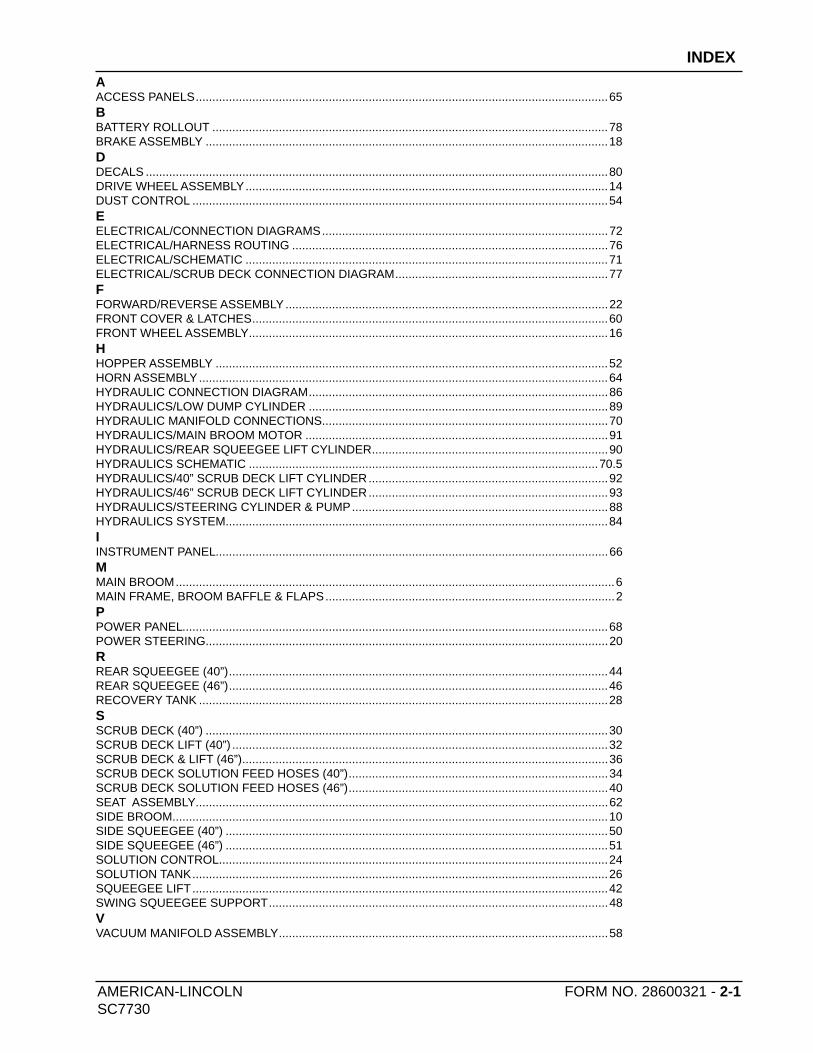
INDEX
C
CONTROLS 20-32
D
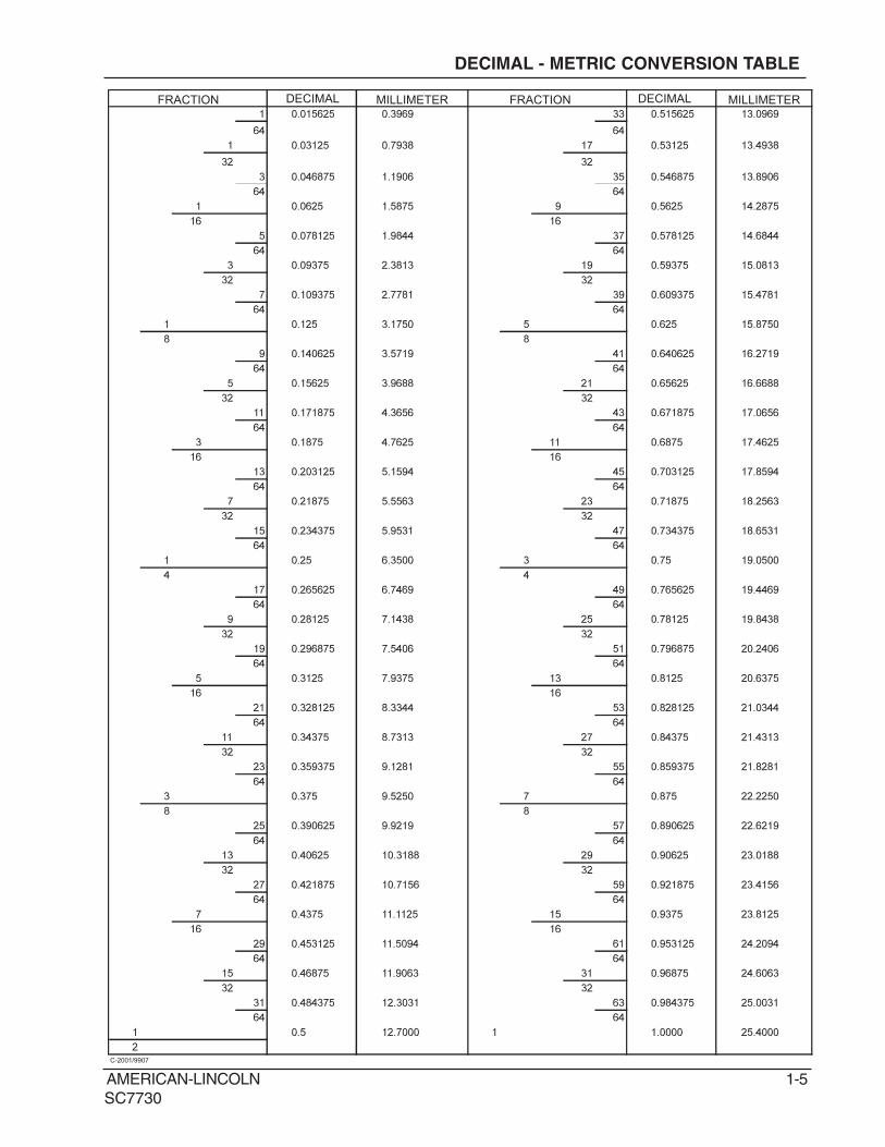
DECIMAL - METRIC CONVERSION TABLE 5
DISCLAIMER 4
H
HARDWARE ABREVIATIONS 6
HYDRAULIC TORQUE REQUIREMENTS 8
M
MACHINE PREPARATION 17, 18, 19
MAINTENANCE 44-58
O
OPERATING INSTRUCTIONS 33-43
ORDERING PARTS 10
S
SAFETY PRECAUTIONS 11, 12
SPECIFICATIONS 14, 15, 16
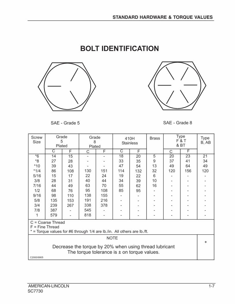
STANDARD HARDWARE & TORQUE VALUES 7
SYMBOLS 9
T
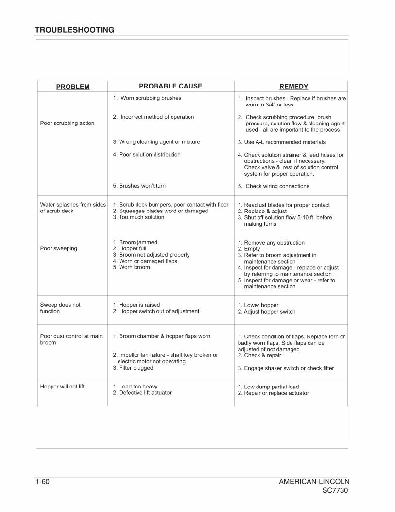
TROUBLESHOOTING 59, 60
1-4 AMERICAN-LINCOLN
SC7730
DISCLAIMER
DISCLAIMER
The information contained in this manual is believed correct at the time of publication. American Lincoln
assumes no responsibility or liability for unauthorized changes made to this manual or pages removed, causing
indirect or consequential damages resulting from the use of the information appearing herein.
WARNING!
In the event that machinery or controls described herein are modified in any way, or in the event that such
machinery or controls are not maintained in a proper manner, the instructional material contained herein may
be rendered inaccurate. The information contained herein is to be used only by persons knowledgeable in the
operation of machinery such as that described herein, or other persons being directly supervised by such
knowledgeable persons.
No portion of this manual may be reproduced without the express written consent of:
AMERICAN LINCOLN
Product Engineering
1100 Haskins Road
Bowling Green, OH, 43402
(419) 352-7511 Fax: (419) 373-4284
Copyright 2003 American Lincoln. All rights reserved.
Parts may be ordered from American-Lincoln authorized distributors. Record the information from the American-Lincoln serial plate to avoiddelays in filling your order:
Parts may be ordered from American-Lincoln authorized distributors. Record the information from the American-Lincoln serial plate to avoiddelays in filling your order:
1. Use the model number, catalog number, and serial number when ordering.2. Give the part number, description, and quantity of parts needed.3. Give shipping instructions for either freight, UPS, or parcel post.
Parts and supplies listed in this manual can be ordered from the following address:
1. Use the model number, catalog number, and serial number when ordering.2. Give the part number, description, and quantity of parts needed.3. Give shipping instructions for either freight, UPS, or parcel post.
Parts and supplies listed in this manual can be ordered from the following address:
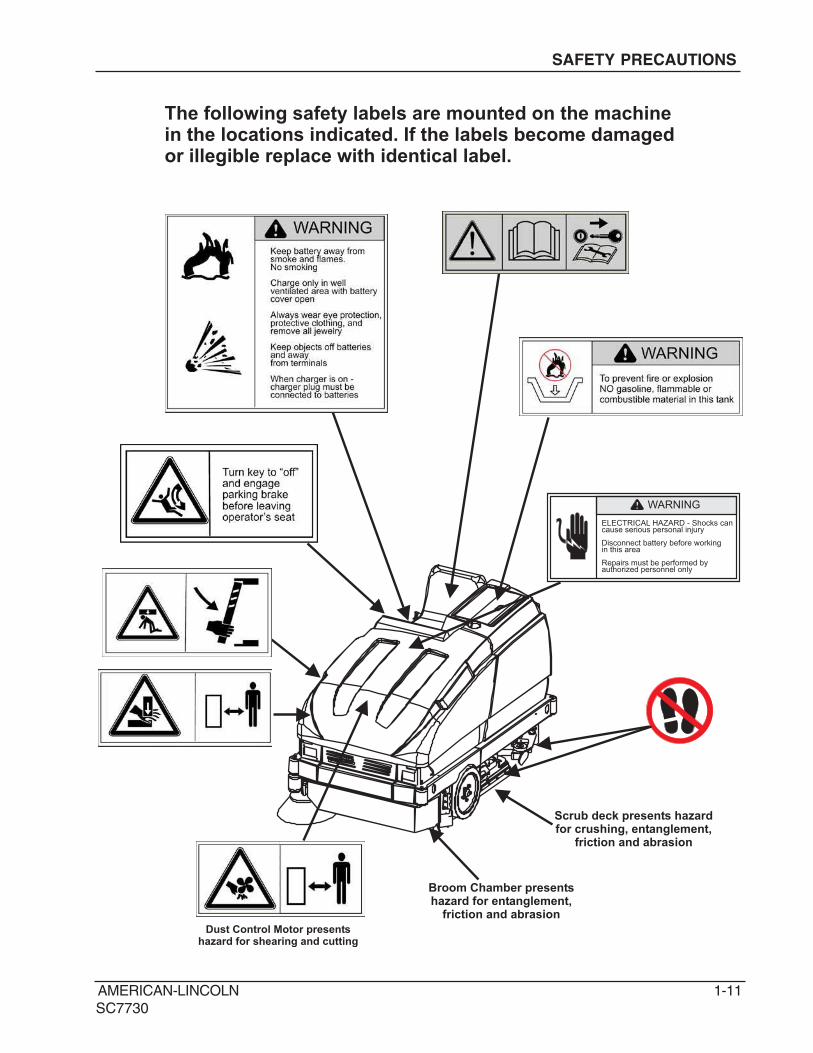
ELECTRICAL HAZARD - Shocks cancause serious personal injury
Disconnect battery before workingin this area
Repairs must be performed byauthorized personnel only
WARNING
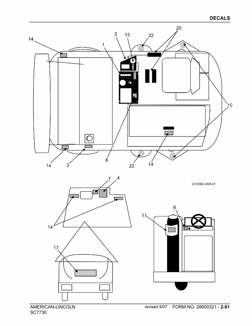
The following safety labels are mounted on the machinein the locations indicated. If the labels become damagedor illegible replace with identical label.
Solution Metering Variable to 3.0 GPM (11.4 lpm)Drain Hose 48 in (122 cm)
Clean Out Port 5.7 in (14.5 cm) heavy debris
HOPPER
Capacity 2.5 cu.ft.(71liter)
DUMP AND LIFT
Dump Height 14 in (35.6 cm.)
SYSTEM FLUID CAPACITIES
Hydraulic System 4.7 Gallons (17.79 Liters)
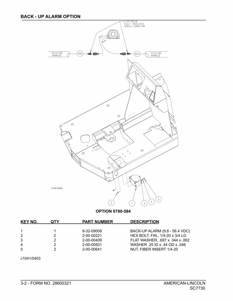
OPTIONAL EQUIPMENT
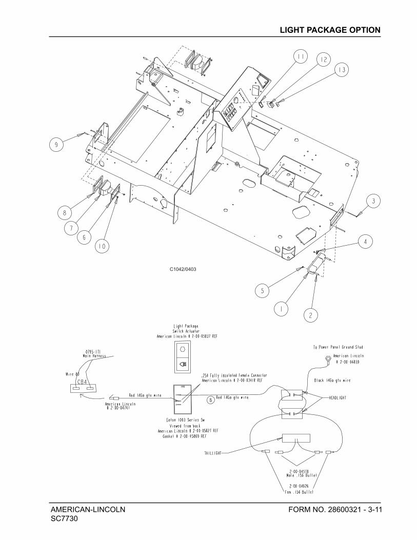
Back-Up Alarm Headlight/Taillights
ESP System Fire Extinguisher
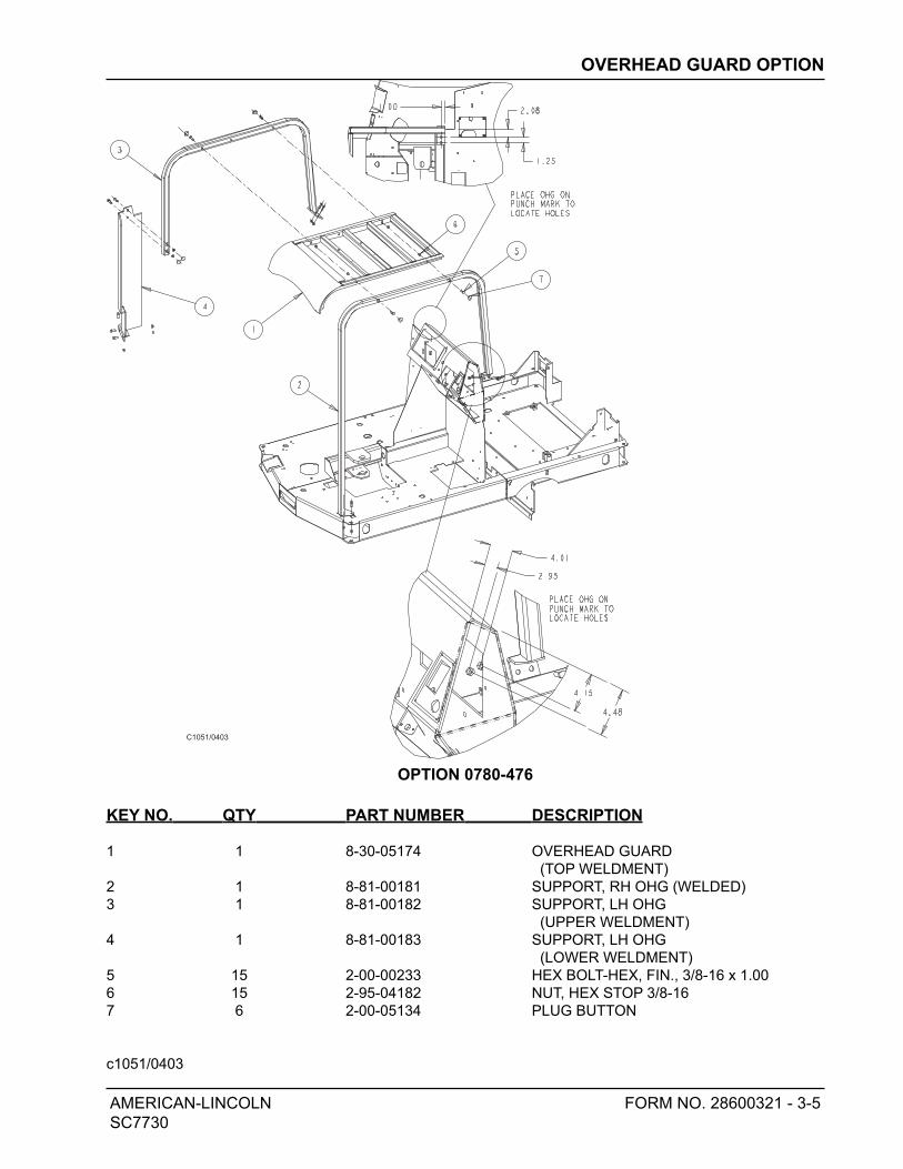
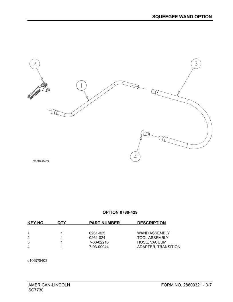
Overhead Guard Squeegee Wand
Spray and Vac Wand Black Nylon Brush
Linatex Squeegee Polypropylene Brush
720 Amp Hour Battery Supergrit Brush
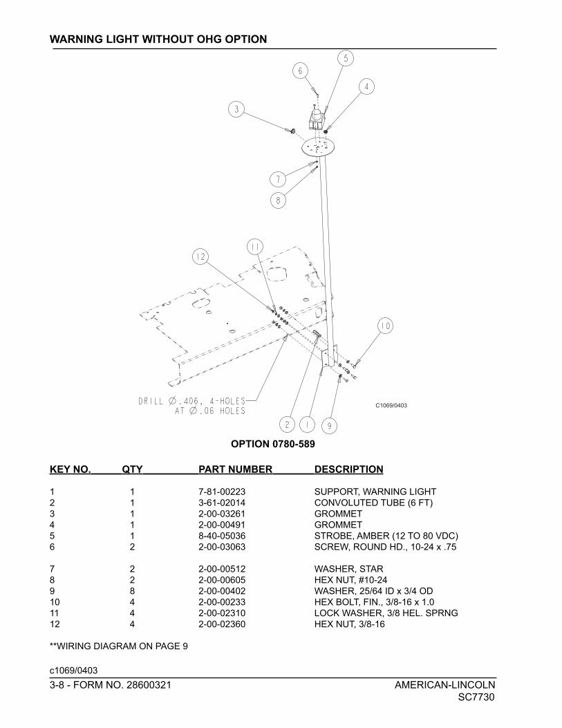
Strobe Light (Amber) Clean Grit Brush
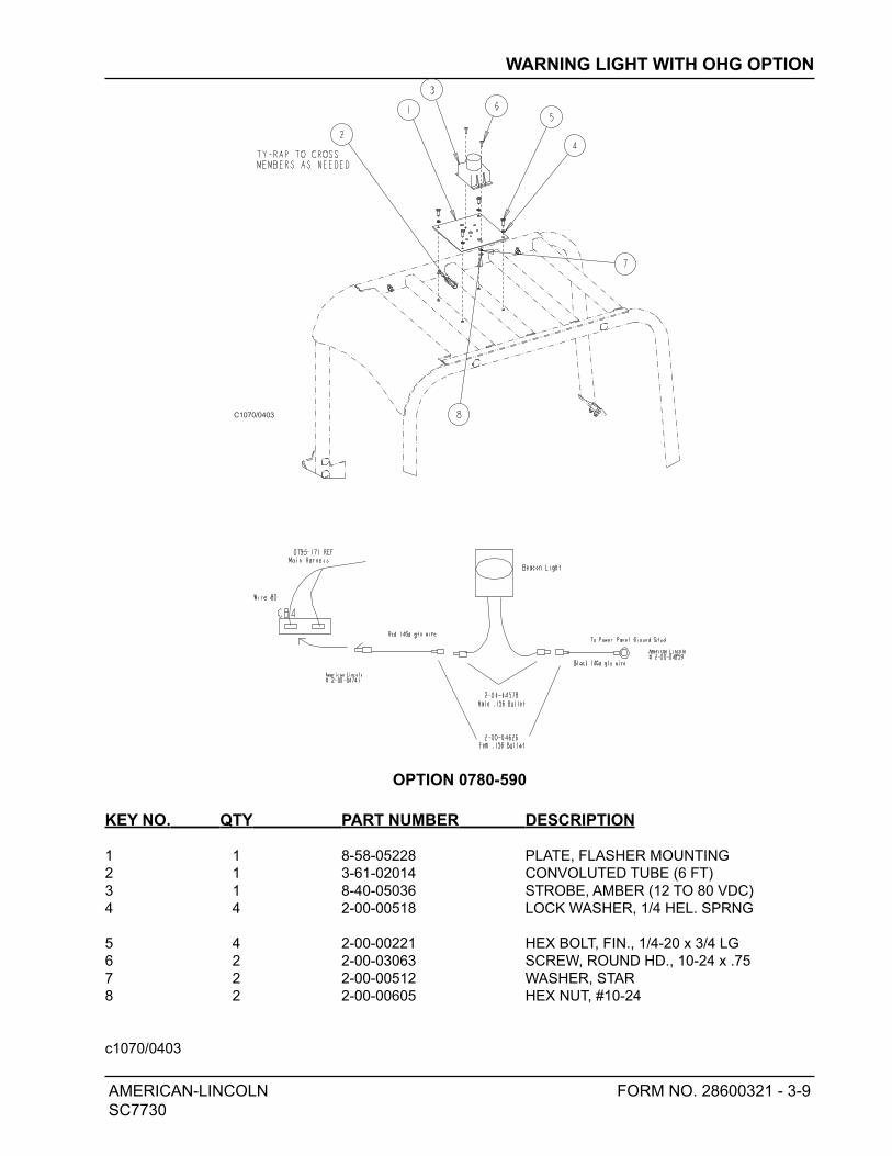
Strobe Light (Amber) W/ OH Guard Arm Rest (RH only)
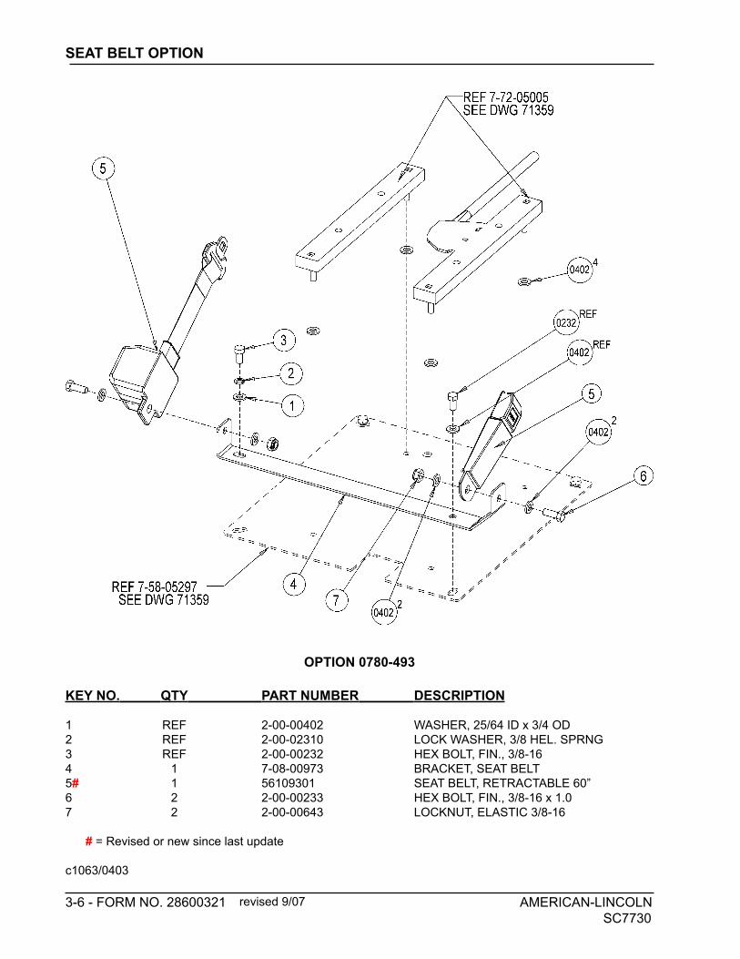
Polyethelyne Panel Filter Seat Belt
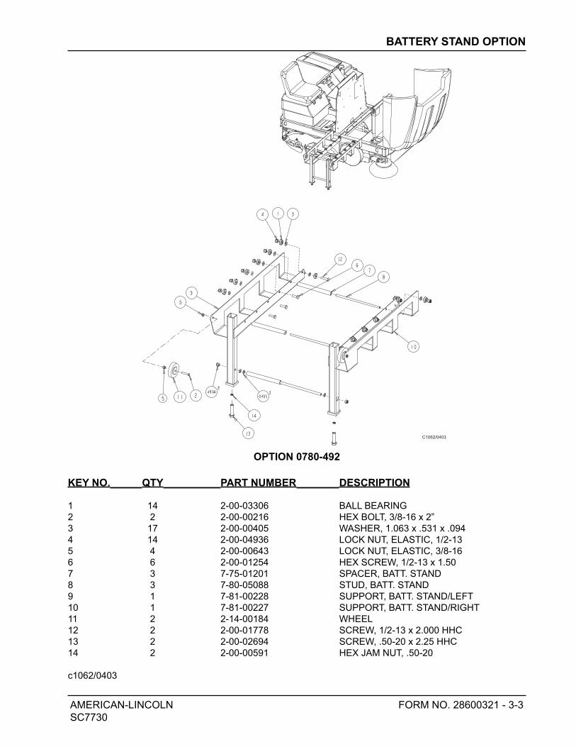
Smart Cart (Battery Roll Out Cart)
1-16 AMERICAN-LINCOLN
SC7730
SPECIFICATIONS
AMERICAN-LINCOLN 1-17
SC7730
MACHINE PREPARATION
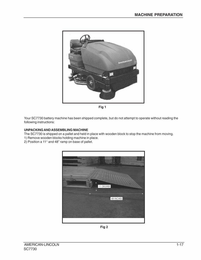
Your SC7730 battery machine has been shipped complete, but do not attempt to operate without reading the
following instructions:
UNPACKING AND ASSEMBLING MACHINE
The SC7730 is shipped on a pallet and held in place with wooden block to stop the machine from moving.
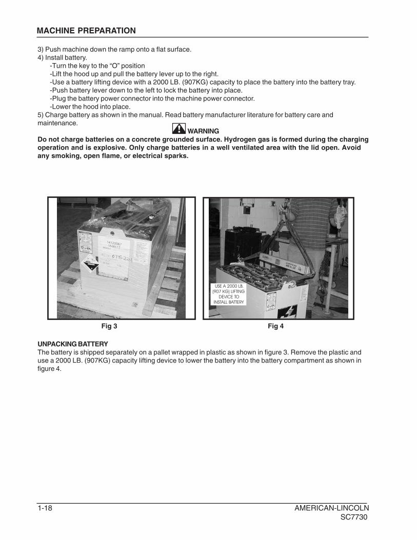
1) Remove wooden blocks holding machine in place.
2) Position a 11° and 48” ramp on base of pallet.
11 DEGREE
48 INCHES
Fig 2
Fig 1
1-18 AMERICAN-LINCOLN
SC7730
MACHINE PREPARATION
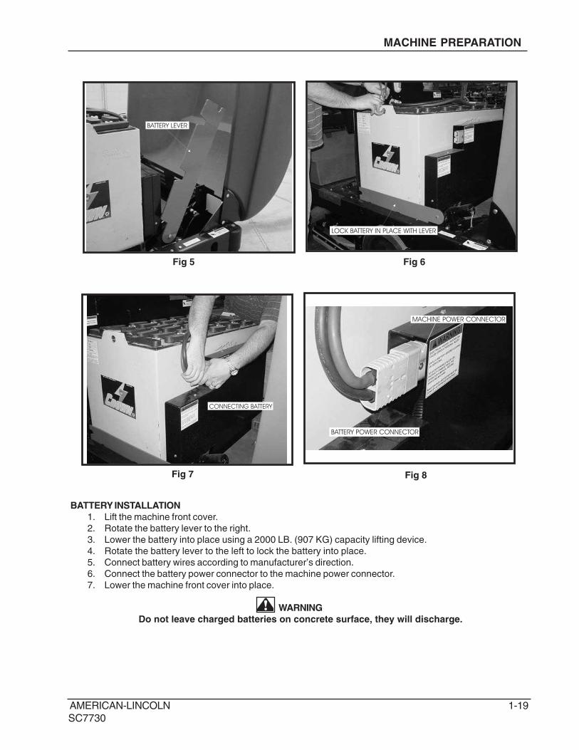
UNPACKING BATTERY
The battery is shipped separately on a pallet wrapped in plastic as shown in figure 3. Remove the plastic and
use a 2000 LB. (907KG) capacity lifting device to lower the battery into the battery compartment as shown in
figure 4.
USE A 2000 LB.
(907 KG) LIFTING
DEVICE TO
INSTALL BATTERY
Fig 3 Fig 4
3) Push machine down the ramp onto a flat surface.
4) Install battery.
-Turn the key to the “O” position
-Lift the hood up and pull the battery lever up to the right.
-Use a battery lifting device with a 2000 LB. (907KG) capacity to place the battery into the battery tray.
-Push battery lever down to the left to lock the battery into place.
-Plug the battery power connector into the machine power connector.
-Lower the hood into place.
5) Charge battery as shown in the manual. Read battery manufacturer literature for battery care and
maintenance.
WARNING
Do not charge batteries on a concrete grounded surface. Hydrogen gas is formed during the charging
operation and is explosive. Only charge batteries in a well ventilated area with the lid open. Avoid
any smoking, open flame, or electrical sparks.
AMERICAN-LINCOLN 1-19
SC7730
MACHINE PREPARATION
BATTERY LEVER
MACHINE POWER CONNECTOR
BATTERY POWER CONNECTOR
CONNECTING BATTERY
LOCK BATTERY IN PLACE WITH LEVER
BATTERY INSTALLATION
1. Lift the machine front cover.
2. Rotate the battery lever to the right.
3. Lower the battery into place using a 2000 LB. (907 KG) capacity lifting device.
4. Rotate the battery lever to the left to lock the battery into place.
5. Connect battery wires according to manufacturer’s direction.
6. Connect the battery power connector to the machine power connector.
7. Lower the machine front cover into place.
WARNING
Do not leave charged batteries on concrete surface, they will discharge.
Fig 5
Fig 7 Fig 8
Fig 6
1-20 AMERICAN-LINCOLN
SC7730
CONTROLS
3
7 8 9 10
11
12 13
14
15
1617
18
19
6
541
2
20
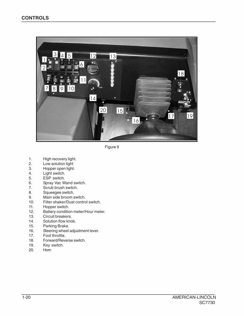
1. High recovery light.
2. Low solution light
3. Hopper open light.
4. Light switch.
5. ESP switch.
6. Spray Vac Wand switch.
7. Scrub brush switch.
8. Squeegee switch.
9. Main side broom switch.
10. Filter shaker/Dust control switch.
11. Hopper switch.
12. Battery condition meter/Hour meter.
13. Circuit breakers.
14. Solution flow knob.
15. Parking Brake.
16. Steering wheel adjustment lever.
17. Foot throttle.
18. Forward/Reverse switch.
19. Key switch.
20. Horn
Figure 9
AMERICAN-LINCOLN 1-21
SC7730
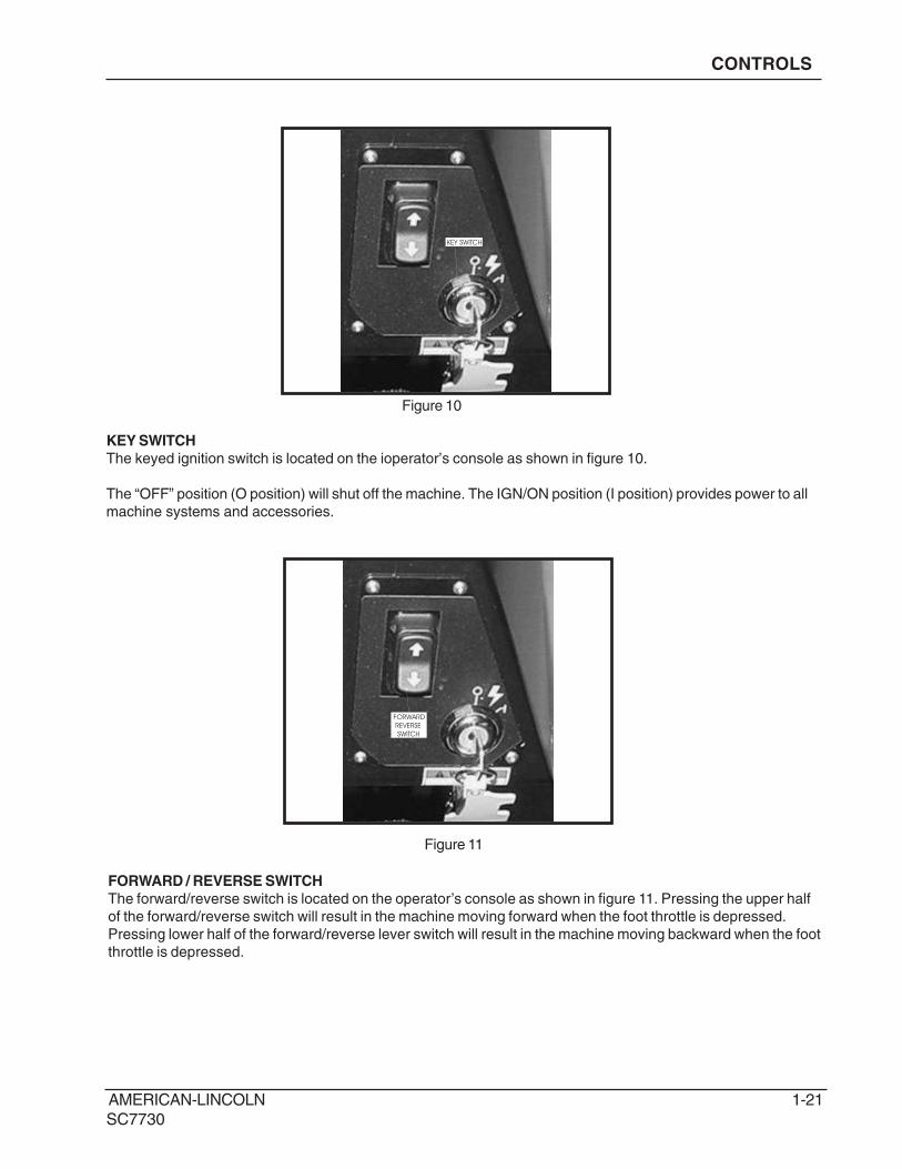
KEY SWITCH
The keyed ignition switch is located on the ioperator’s console as shown in figure 10.
The “OFF” position (O position) will shut off the machine. The IGN/ON position (I position) provides power to all
machine systems and accessories.
KEY SWITCH
CONTROLS
Figure 10
Figure 11
FORWARD
REVERSE
SWITCH
FORWARD / REVERSE SWITCH
The forward/reverse switch is located on the operator’s console as shown in figure 11. Pressing the upper half
of the forward/reverse switch will result in the machine moving forward when the foot throttle is depressed.
Pressing lower half of the forward/reverse lever switch will result in the machine moving backward when the foot
throttle is depressed.
1-22 AMERICAN-LINCOLN
SC7730
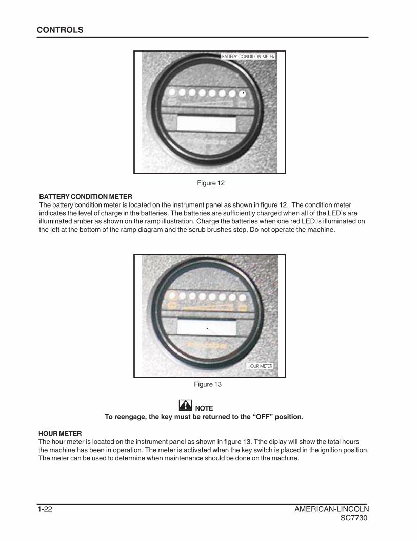
NOTE
To reengage, the key must be returned to the “OFF” position.
HOUR METER
The hour meter is located on the instrument panel as shown in figure 13. Tthe diplay will show the total hours
the machine has been in operation. The meter is activated when the key switch is placed in the ignition position.
The meter can be used to determine when maintenance should be done on the machine.
HOUR METER
Figure 12
Figure 13
CONTROLS
BATTERY CONDITION METER
BATTERY CONDITION METER
The battery condition meter is located on the instrument panel as shown in figure 12. The condition meter
indicates the level of charge in the batteries. The batteries are sufficiently charged when all of the LED’s are
illuminated amber as shown on the ramp illustration. Charge the batteries when one red LED is illuminated on
the left at the bottom of the ramp diagram and the scrub brushes stop. Do not operate the machine.
AMERICAN-LINCOLN 1-23
SC7730
CONTROLS
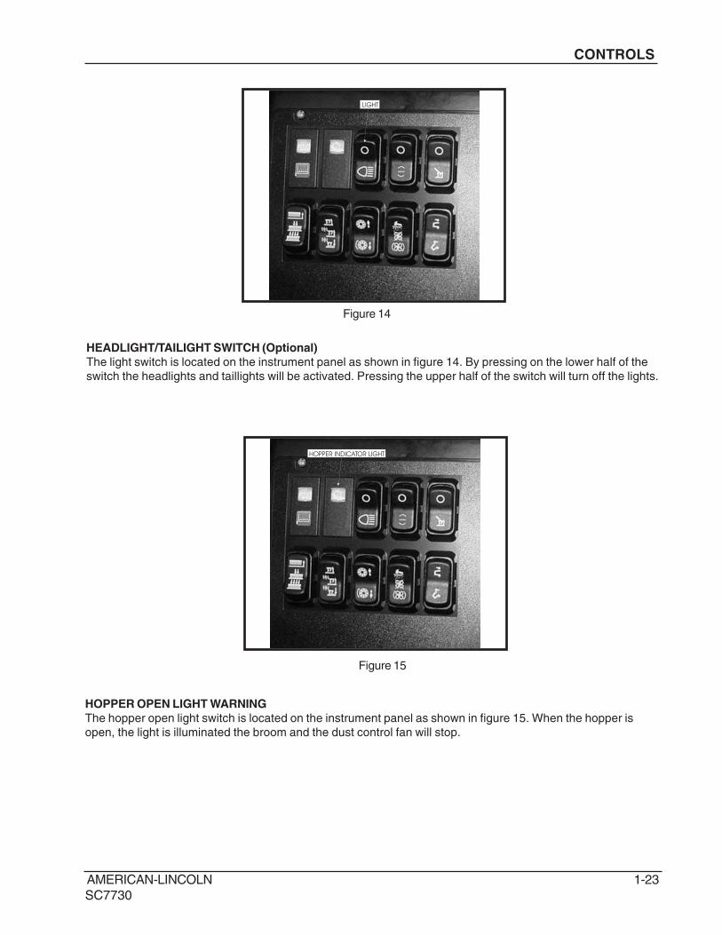
Figure 14
LIGHT
HEADLIGHT/TAILIGHT SWITCH (Optional)
The light switch is located on the instrument panel as shown in figure 14. By pressing on the lower half of the
switch the headlights and taillights will be activated. Pressing the upper half of the switch will turn off the lights.
HOPPER INDICATOR LIGHT
HOPPER OPEN LIGHT WARNING
The hopper open light switch is located on the instrument panel as shown in figure 15. When the hopper is
open, the light is illuminated the broom and the dust control fan will stop.
Figure 15
1-24 AMERICAN-LINCOLN
SC7730
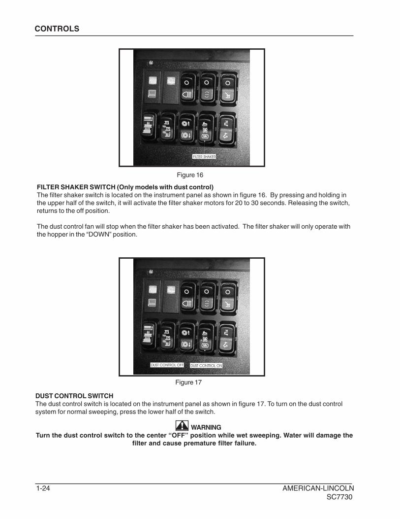
FILTER SHAKER
DUST CONTROL ONDUST CONTROL OFF
CONTROLS
Figure 16
Figure 17
FILTER SHAKER SWITCH (Only models with dust control)
The filter shaker switch is located on the instrument panel as shown in figure 16. By pressing and holding in
the upper half of the switch, it will activate the filter shaker motors for 20 to 30 seconds. Releasing the switch,
returns to the off position.
The dust control fan will stop when the filter shaker has been activated. The filter shaker will only operate with
the hopper in the “DOWN” position.
DUST CONTROL SWITCH
The dust control switch is located on the instrument panel as shown in figure 17. To turn on the dust control
system for normal sweeping, press the lower half of the switch.
WARNING
Turn the dust control switch to the center “OFF” position while wet sweeping. Water will damage the
filter and cause premature filter failure.
AMERICAN-LINCOLN 1-25
SC7730
SCRUB BRUSHES
SQUEEGEE
CONTROLS
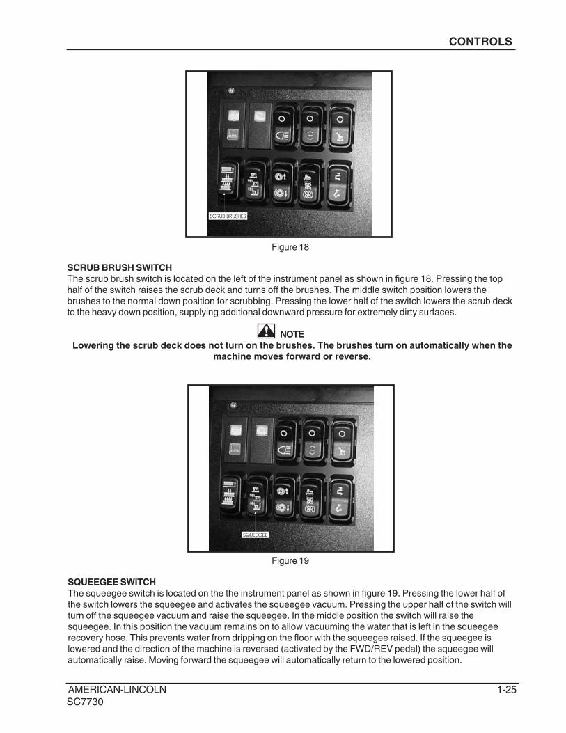
Figure 18
Figure 19
SCRUB BRUSH SWITCH
The scrub brush switch is located on the left of the instrument panel as shown in figure 18. Pressing the top
half of the switch raises the scrub deck and turns off the brushes. The middle switch position lowers the
brushes to the normal down position for scrubbing. Pressing the lower half of the switch lowers the scrub deck
to the heavy down position, supplying additional downward pressure for extremely dirty surfaces.
NOTE
Lowering the scrub deck does not turn on the brushes. The brushes turn on automatically when the
machine moves forward or reverse.
SQUEEGEE SWITCH
The squeegee switch is located on the the instrument panel as shown in figure 19. Pressing the lower half of
the switch lowers the squeegee and activates the squeegee vacuum. Pressing the upper half of the switch will
turn off the squeegee vacuum and raise the squeegee. In the middle position the switch will raise the
squeegee. In this position the vacuum remains on to allow vacuuming the water that is left in the squeegee
recovery hose. This prevents water from dripping on the floor with the squeegee raised. If the squeegee is
lowered and the direction of the machine is reversed (activated by the FWD/REV pedal) the squeegee will
automatically raise. Moving forward the squeegee will automatically return to the lowered position.
1-26 AMERICAN-LINCOLN
SC7730
LOW SOLUTION LIGHT
HIGH RECOVERY LIGHT
CONTROLS
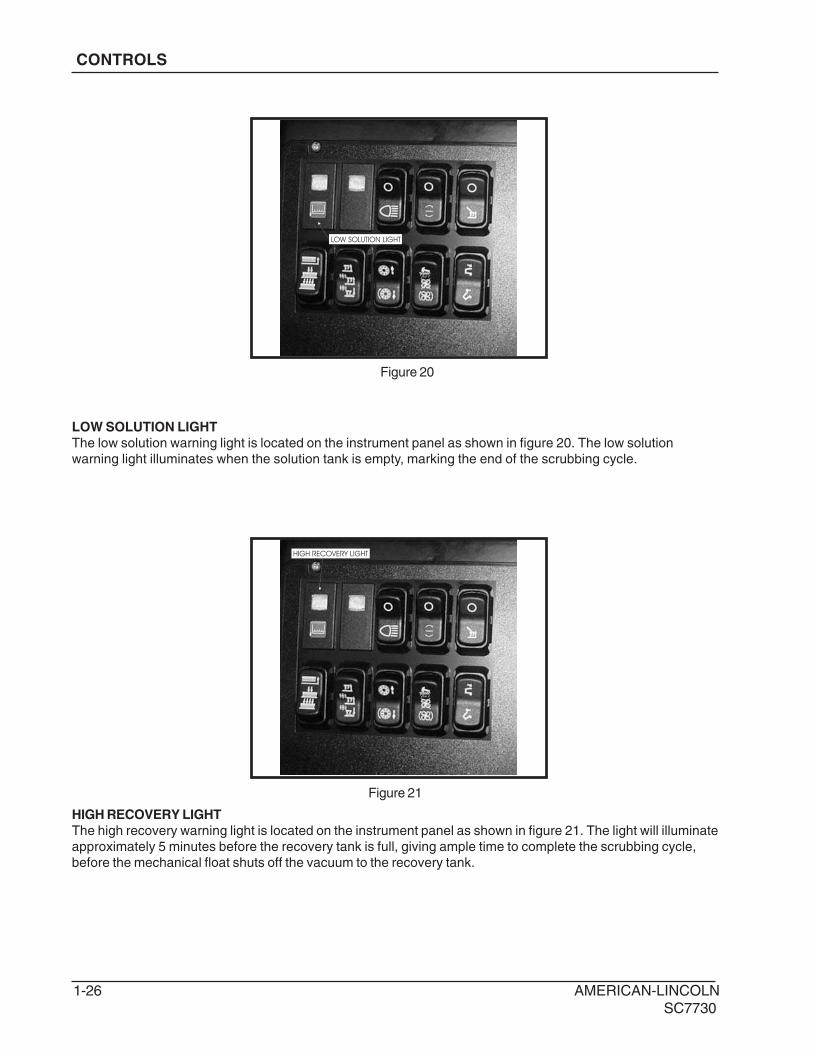
Figure 20
Figure 21
LOW SOLUTION LIGHT
The low solution warning light is located on the instrument panel as shown in figure 20. The low solution
warning light illuminates when the solution tank is empty, marking the end of the scrubbing cycle.
HIGH RECOVERY LIGHT
The high recovery warning light is located on the instrument panel as shown in figure 21. The light will illuminate
approximately 5 minutes before the recovery tank is full, giving ample time to complete the scrubbing cycle,
before the mechanical float shuts off the vacuum to the recovery tank.
AMERICAN-LINCOLN 1-27
SC7730
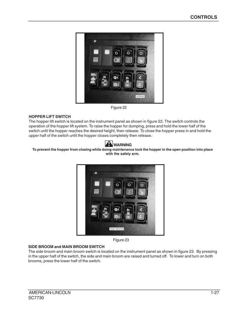
HOPPER
HOPPER LIFT SWITCH
The hopper lift switch is located on the instrument panel as shown in figure 22. The switch controls the
operation of the hopper lift system. To raise the hopper for dumping, press and hold the lower half of the
switch until the hopper reaches the desired height, then release. To close the hopper press in and hold the
upper half of the switch until the hopper closes completely then release.
WARNINGTo prevent the hopper from closing while doing maintenance lock the hopper in the open position into place
with the safety arm.
Figure 22
CONTROLS
MAIN BROOM
Figure 23
SIDE BROOM and MAIN BROOM SWITCH
The side broom and main broom switch is located on the instrument panel as shown in figure 23. By pressing
in the upper half of the switch, the side and main broom are raised and turned off. To lower and turn on both
brooms, press the lower half of the switch.
1-28 AMERICAN-LINCOLN
SC7730
SPRAY VACCUM
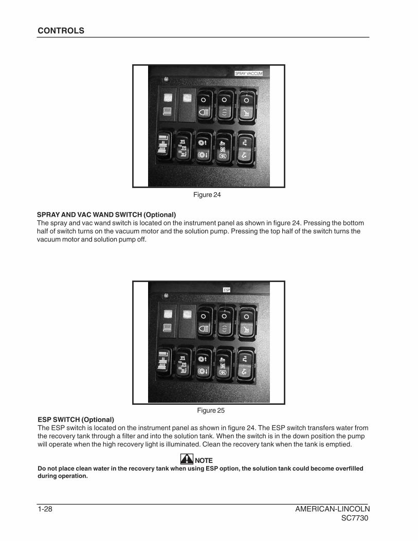
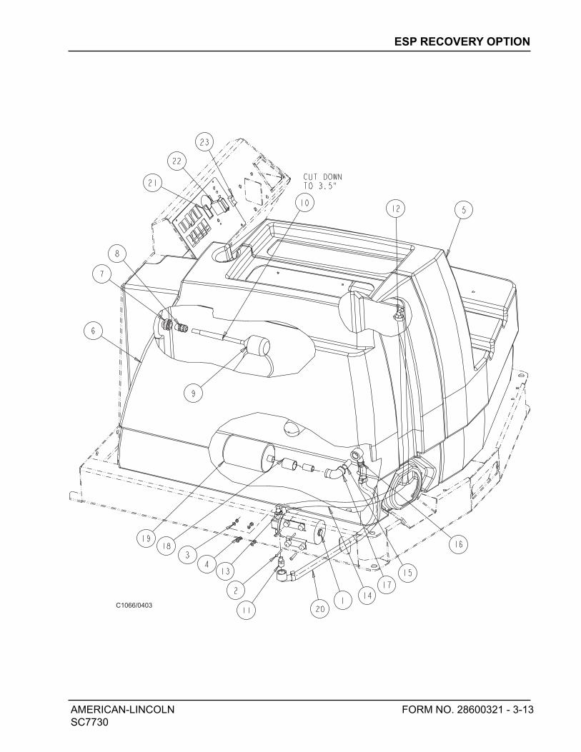
ESP SWITCH (Optional)
The ESP switch is located on the instrument panel as shown in figure 24. The ESP switch transfers water from
the recovery tank through a filter and into the solution tank. When the switch is in the down position the pump
will operate when the high recovery light is illuminated. Clean the recovery tank when the tank is emptied.
NOTEDo not place clean water in the recovery tank when using ESP option, the solution tank could become overfilled
during operation.
ESP
Figure 24
Figure 25
CONTROLS
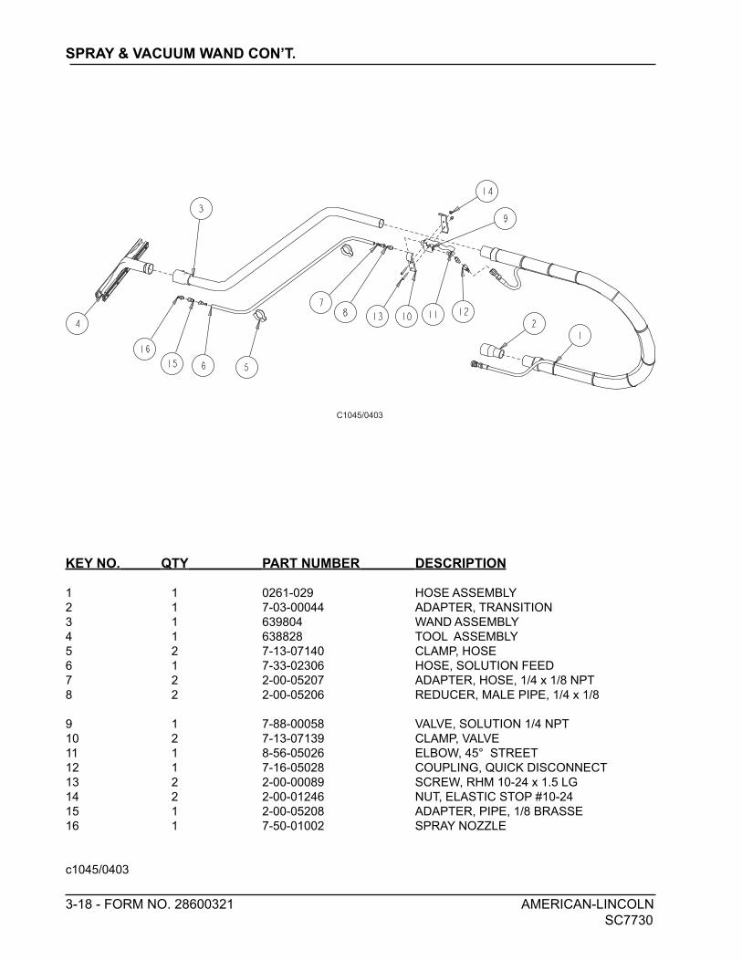
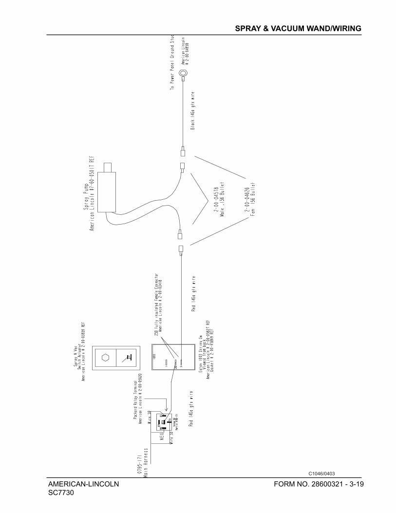
SPRAY AND VAC WAND SWITCH (Optional)
The spray and vac wand switch is located on the instrument panel as shown in figure 24. Pressing the bottom
half of switch turns on the vacuum motor and the solution pump. Pressing the top half of the switch turns the
vacuum motor and solution pump off.
AMERICAN-LINCOLN 1-29
SC7730
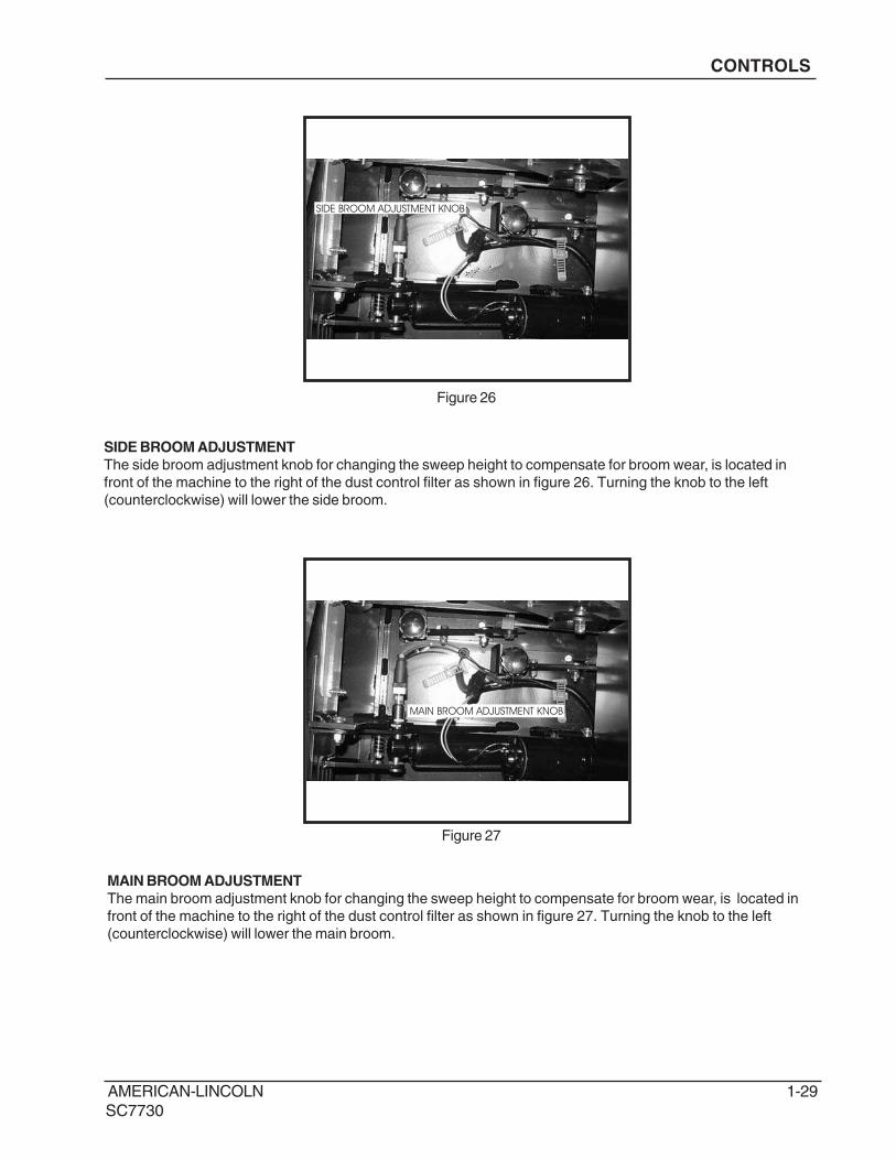
SIDE BROOM ADJUSTMENT KNOB
MAIN BROOM ADJUSTMENT KNOB
MAIN BROOM ADJUSTMENT
The main broom adjustment knob for changing the sweep height to compensate for broom wear, is located in
front of the machine to the right of the dust control filter as shown in figure 27. Turning the knob to the left
(counterclockwise) will lower the main broom.
CONTROLS
Figure 27
Figure 26
SIDE BROOM ADJUSTMENT
The side broom adjustment knob for changing the sweep height to compensate for broom wear, is located in
front of the machine to the right of the dust control filter as shown in figure 26. Turning the knob to the left
(counterclockwise) will lower the side broom.
1-30 AMERICAN-LINCOLN
SC7730
CONTROLS
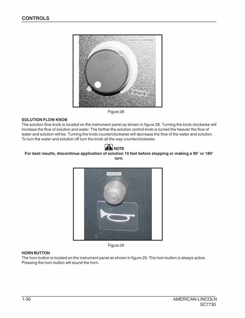
Figure 28
SOLUTION FLOW KNOB
SOLUTION FLOW KNOB
The solution flow knob is located on the instrument panel as shown in figure 28. Turning the knob clockwise will
increase the flow of solution and water. The farther the solution control knob is turned the heavier the flow of
water and solution will be. Turning the knob counterclockwise will decrease the flow of the water and solution.
To turn the water and solution off turn the knob all the way counterclockwise.
NOTE
For best results, discontinue application of solution 10 feet before stopping or making a 90° or 180°
turn.
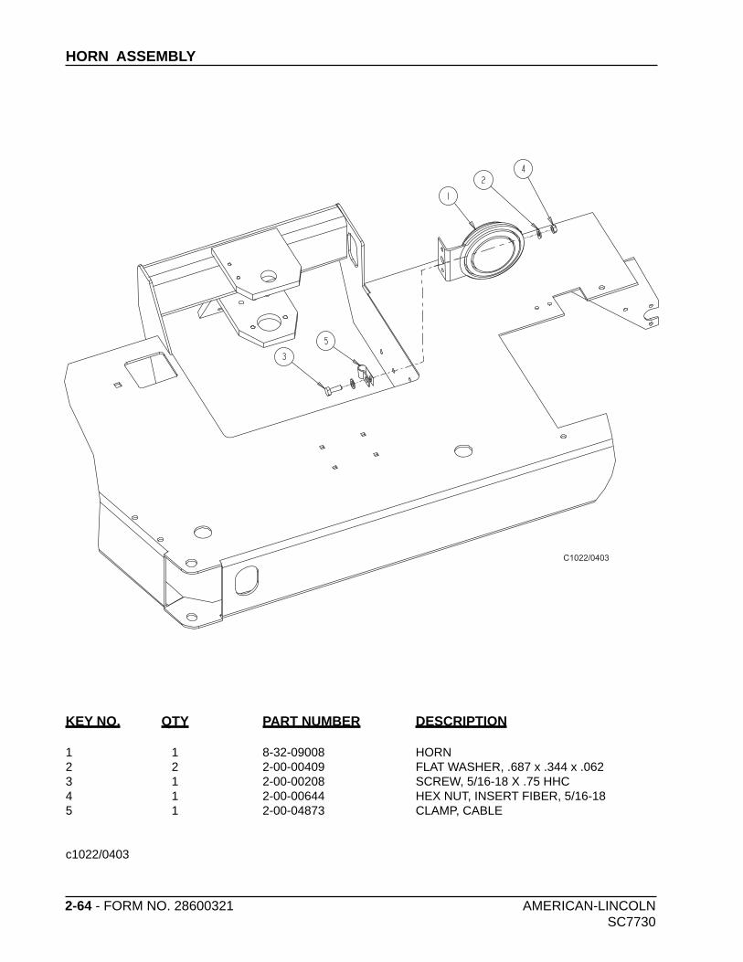
HORN BUTTON
HORN BUTTON
The horn button is located on the instrument panel as shown in figure 29. The horn button is always active.
Pressing the horn button will sound the horn.
Figure 29
AMERICAN-LINCOLN 1-31
SC7730
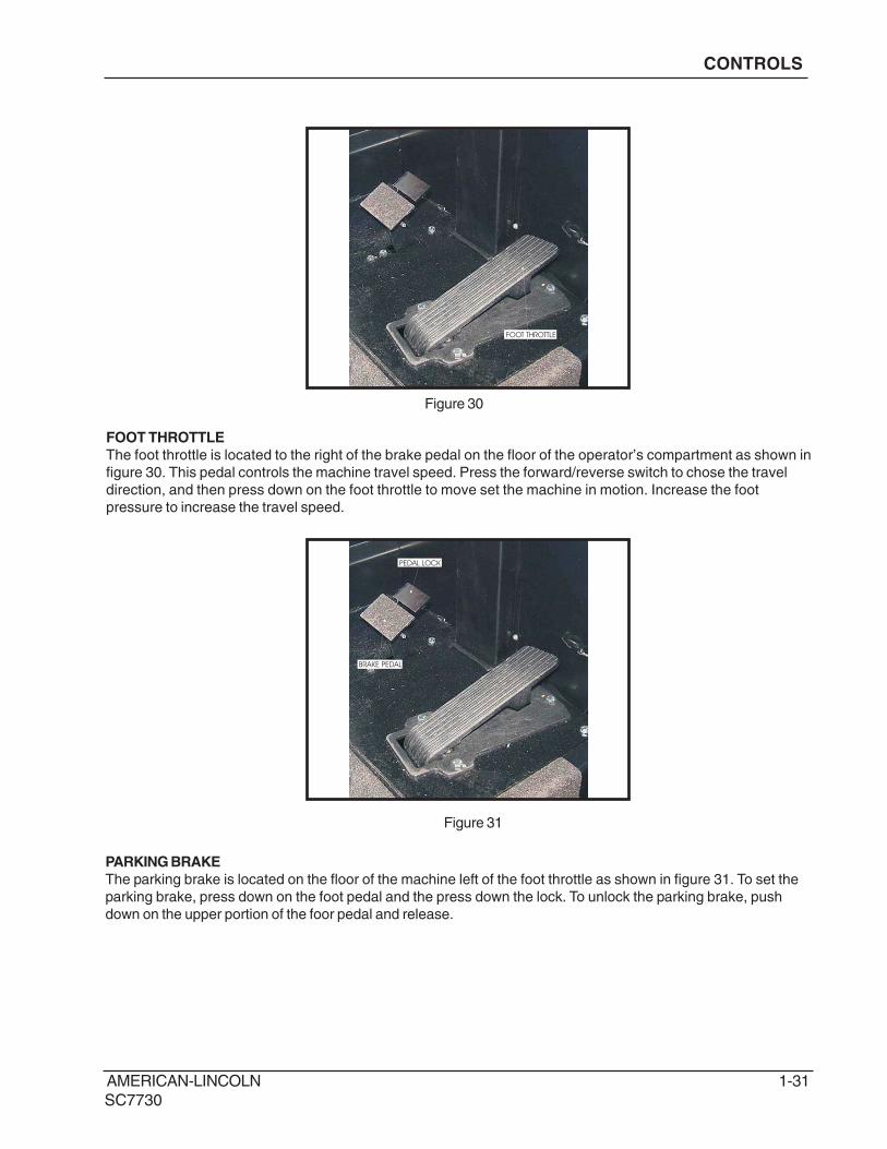
FOOT THROTTLE
FOOT THROTTLE
The foot throttle is located to the right of the brake pedal on the floor of the operator’s compartment as shown in
figure 30. This pedal controls the machine travel speed. Press the forward/reverse switch to chose the travel
direction, and then press down on the foot throttle to move set the machine in motion. Increase the foot
pressure to increase the travel speed.
Figure 30
BRAKE PEDAL
PEDAL LOCK
PARKING BRAKE
The parking brake is located on the floor of the machine left of the foot throttle as shown in figure 31. To set the
parking brake, press down on the foot pedal and the press down the lock. To unlock the parking brake, push
down on the upper portion of the foor pedal and release.
Figure 31
CONTROLS
1-32 AMERICAN-LINCOLN
SC7730
CONTROLS
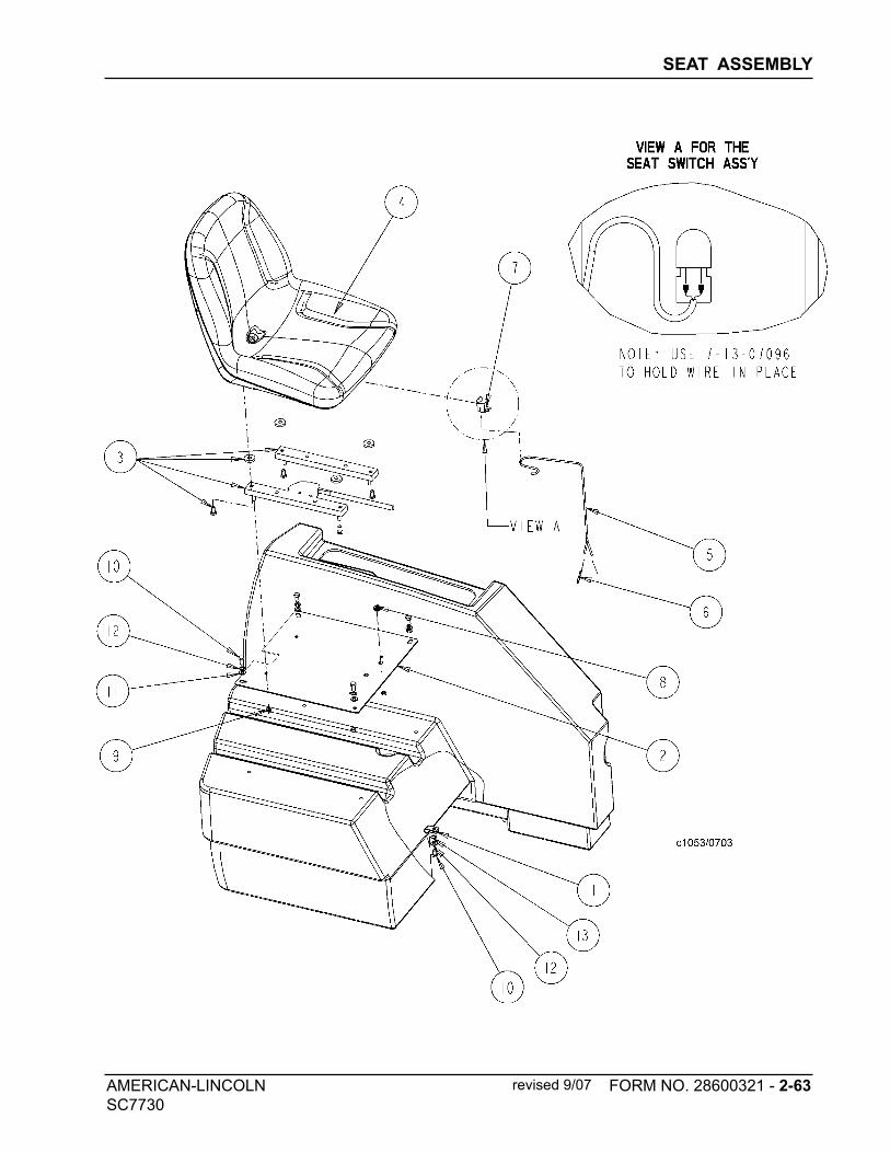
SEAT ADJUSTMENT LEVER
SEAT POSITION ADJUSTMENT
The seat position adjustment lever is located on the front of the seat to the left as seen in figure 34. The lever is
spring loaded to the lock position. To adjust the seat, push the lever to the left and move the seat to the desired
position and then release the lever to lock the seat into place.
Figure 34
SAFETY FEATURES
SEAT SAFETY SWITCH - Machine will not move and parking brake will set if this switch is not activated.
SPEED INTERLOCK - Maximum machine speed will be reduced while scrub brushes are in use.
BRUSHES OFF IN NEUTRAL - Scrub brushes automatically disengage when machine is idle.
AUTOMATIC RECOVERY VACUUM SHUT-OFF - Vacuum fans will shut down when recovery tank is full.
AMERICAN-LINCOLN 1-33
SC7730
OPERATING INSTRUCTIONS
NOTEBefore starting the engine, perform the pre-start checklist.Before starting the engine, perform the pre-start
checklist.
PRE-START CHECKLIST
Check hydraulic fluid level.
Check all systems for leaks.
Check brakes and controls for proper operation.
Check broom patterns.
Check hydraulic fluid level.
Check hydraulic connections for leaks.
Check brakes and controls for proper operation.
Check broom pattern.
Check to ensure that all covers, panels and access doors are securely closed.
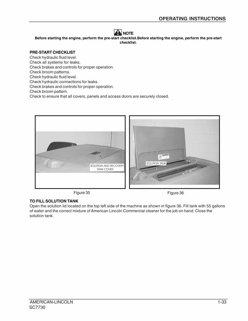
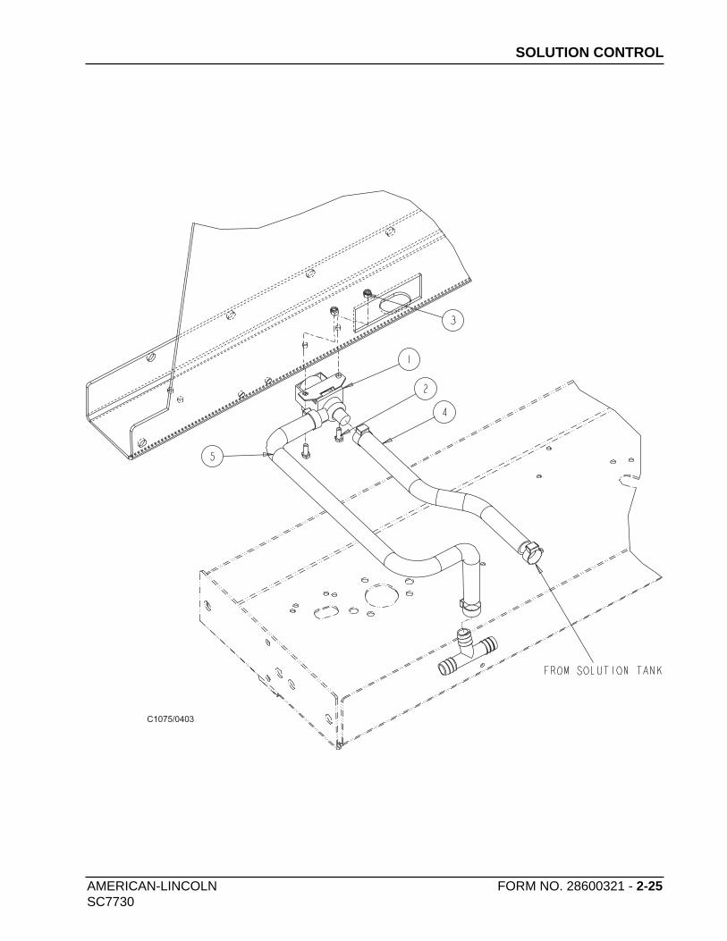
SOLUTION TANK
Figure 35
TO FILL SOLUTION TANK
Open the solution lid located on the top left side of the machine as shown in figure 36. Fill tank with 55 gallons
of water and the correct mixture of American Lincoln Commercial cleaner for the job on hand. Close the
solution tank.
SOLUTION AND RECOVERY
TANK COVER
Figure 36
1-34 AMERICAN-LINCOLN
SC7730
OPERATING INSTRUCTIONS
TO START MACHINE
Turn key to “I” position.
TO TRANSPORT MACHINE
1. Make sure the brushes and squeegees are in the up or raised position with all other controls in the off
position.
2. Release the parking brake.
3. Push the forward/reverse switch to desired position (up for forward and down for reverse)
4. Push down on the foot throttle to obtain desired travel speed.
5. Release the foot throttle to slow down or stop when on a flat surface. To slow the machine when
decending down an inclined surface reduce foot pedal pressure.
NOTEThe pedal proportional braking sytem is designed to regulate machine speed according to the foot thottle
position. This sytem is designed to bring the machine to a stop in controlled manner. When driving down an
inclined surface, reduce foot pedal pressure rather than releasing the foot throttle. This will provide a controlled
stop and prevent the drive wheel from locking.
WARNING
Do not turn the steering wheel sharply when the machine is in motion. The sweeper is very
responsive to movement of the steering wheel. Do not make sudden turns.
AMERICAN-LINCOLN 1-35
SC7730
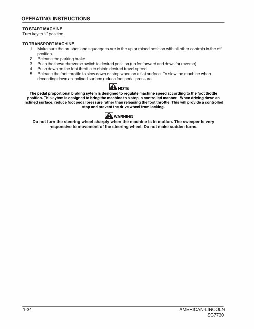
REAR SQUEEGEE
TO BEGIN THE CLEANING OPERATION
1. Select the operating mode
NORMAL = ESP
2. Lower brushes to the desired position.
SCRUB DECK = NORMAL RANGE OR HEAVY
3. Place the squeegee switch in the lower position.
SQUEEGEE BLADE = LOWER
4. Move solution control knob to the desired setting and begin operation.
SCRUBBING THE AVERAGE FLOOR WITH LIGHT TO MEDIUM SOILAGE
In this operation, cleaning is accomplished in one pass, with simultaneous solution feed, scrubbing and dirty
water pick up. The rate of solution feed and the speed of travel required will vary with floor condition. This
knowledge will come with operator experience.
Figure 38
OPERATING INSTRUCTIONS
1-36 AMERICAN-LINCOLN
SC7730
SOLUTIONTANK
RECOVERYTANK
STRAINER
SCRUBBRUSH SQUEEGEE
FLOOR CONTACT
SOLUTIONCONTROLVALVE
SOLUTIONCONTROLVALVE
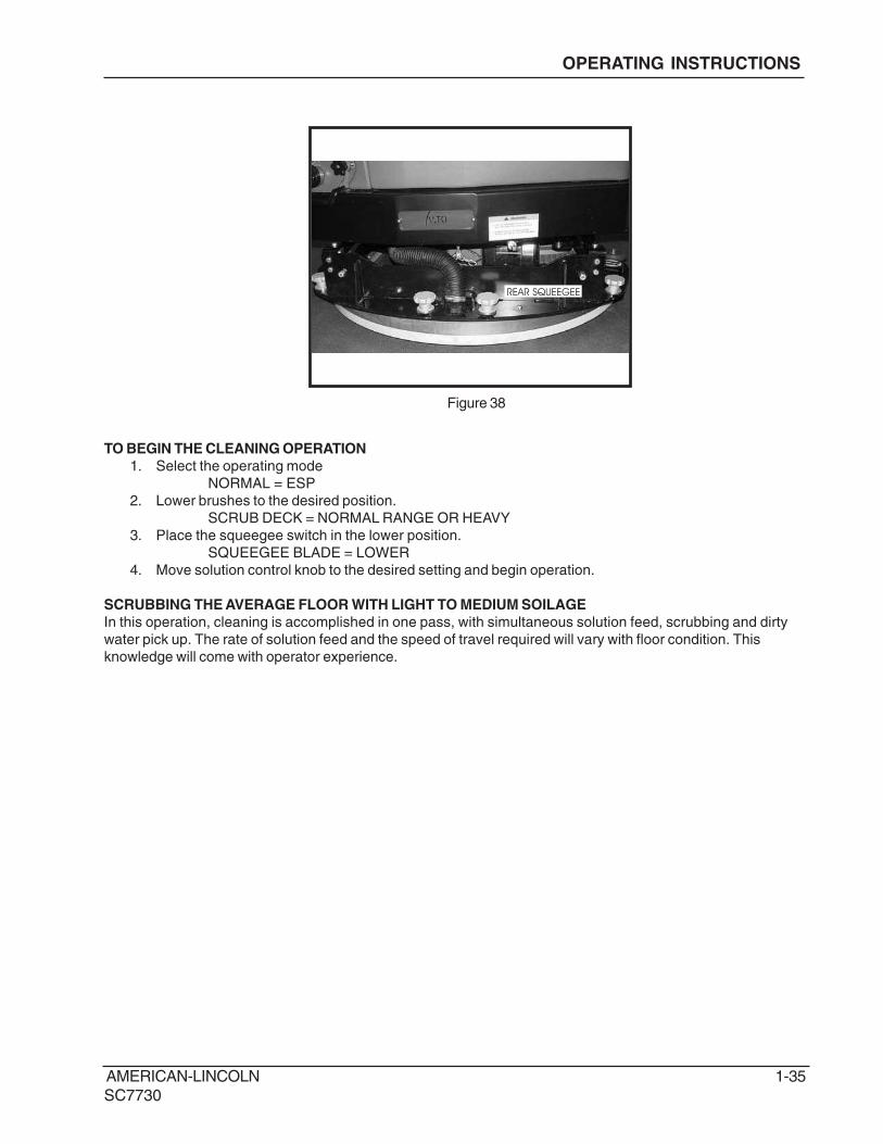
THE NON-RECYCLING OR STANDARD SCRUBBING MODE
During the scrubbing process, detergent solution water from the solution tank is fed to the solution line. There it
is fed to the floor where three disc scrubbing brushes work to dislodge soil. After scrubbing, the dirty solution is
vacuumed from the floor and discharged into the containment chamber in the forward portion of the recovery
tank, where a system of baffles helps to clarify the solution.
Sensors in each tank will indicate, by lights on the control panel, when the water in the solution tank is too low
or when the water in the recovery tank is too high.
Fig. 39
OPERATING INSTRUCTIONS
AMERICAN-LINCOLN 1-37
SC7730
SOLUTIONTANK
RECOVERYTANK
SOLUTIONCONTROL
VALVE
SCRUBBRUSH
SQUEEGEE
FLOOR CONTACT
STRAINER
SOLUTIONPUMP
STRAINER
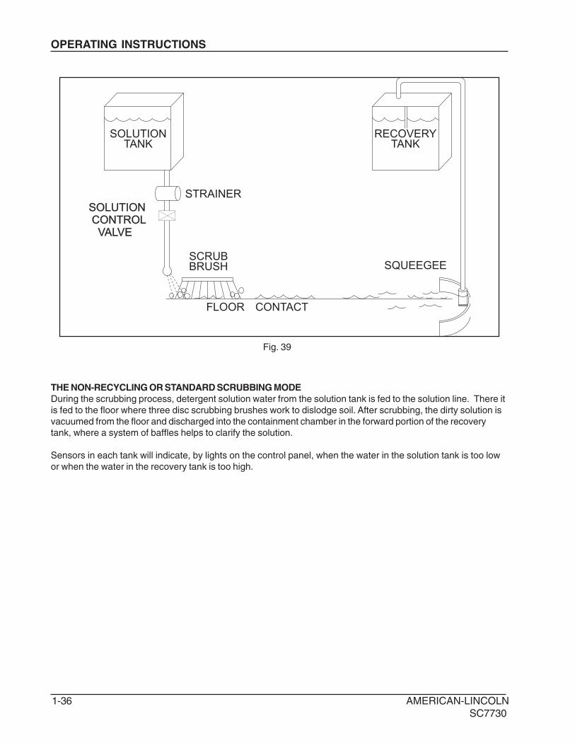
ESP OPERATING MODE
During the scrubbing process, filtered water from the solution tank is fed to the solution line, where it combines
with detergent. This mixture is then fed to the floor where two or three disc scrubbing brushes work to dislodge
soil. After scrubbing, the dirty solution is vacuumed from the floor and discharged into the recovery tank. At
intervals, a float switch activates the recycling pump, which sends filtered solution from the recovery tank to the
solution tank.
Fig. 40
OPERATING INSTRUCTIONS
1-38 AMERICAN-LINCOLN
SC7730
SCRUBBING PATH
· Scrub in straight paths. Do not bump posts. Do not scrape the sides of the machine.
· When the machine is in motion, do not push the directional/speed control pedal all the way forward.
This is the same as starting in “high” and will put a strain on the motor and drive system.
· Plan your sweeping and scrubbing in advance. Try to arrange long runs with minimum stopping and
starting. Sweep debris from narrow aisles out into main aisle ahead of time. Do an entire floor, or
section at on time.
· Pick up oversize debris before sweeping.
· Allow a few inches of overlap of sweep and scrub paths. This will eliminate leaving dirty patches.
· Allow a few inches of overlap of sweep and scrub paths. This will eliminate leaving dirty patches.
· Don’t turn steering wheel to sharply when machine is in motion. The machine is very responsive to
movement of the steering wheel; so avoid sudden turns.
· Try to follow as straight a path as possible. Avoid bumping into posts or scraping the sides of the
machine.
· When placing the machine in motion, avoid slamming the directional control pedal all the way
forward suddenly. This is equivalent to starting out in “HIGH” and puts needless strain on the drive
system. Periodically, turn the sweeping broom end for end to prevent the bristles from “settling” in
one direction.
TO STOP THE CLEANING OPERATION
Discontinue the cleaning operation when the low solution light or the high recovery light illuminates, this
indicates the solution tank is empty or recovery tank is full. Discontinue the scrubbing cycle, put all controls in
the forward position for transport and drive to the drain area.
NOTE
After stopping, perform these post operation checks.
P4134/0001
SIDE AISLES
MAIN AISLE
SIDE AISLES
Fig. 41
OPERATING INSTRUCTIONS
AMERICAN-LINCOLN 1-39
SC7730
POST OPERATION CHECKLIST
Check Battery Condition and recharge, if necessary.
1. Check all flaps for wear, damage and adjustment.
2. Drain and clean recovery tank.
3. Clean recovery tank screen and float.
4. Check scrub brushes for wear or damage.
5. Check rear and side squeegee for wear, damage and adjustment.
6. Clean the debris in hopper
7. Check main and side broom for wear or damage.
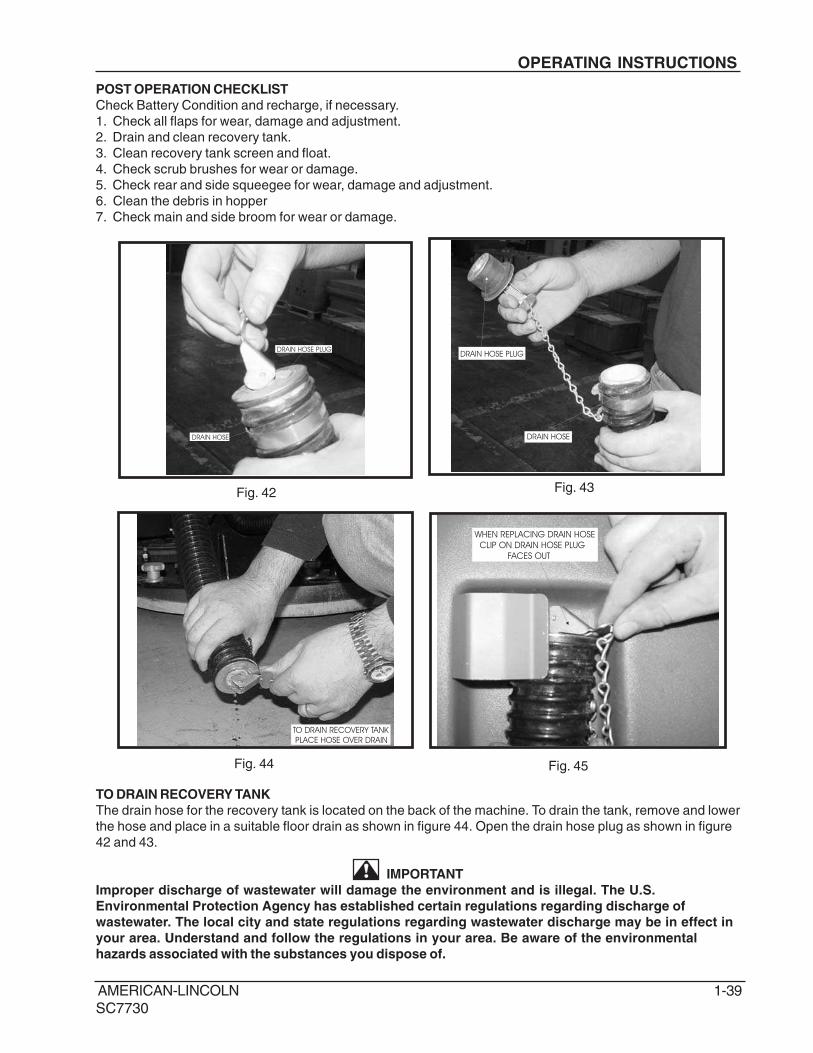
TO DRAIN RECOVERY TANK
The drain hose for the recovery tank is located on the back of the machine. To drain the tank, remove and lower
the hose and place in a suitable floor drain as shown in figure 44. Open the drain hose plug as shown in figure
42 and 43.
IMPORTANT
Improper discharge of wastewater will damage the environment and is illegal. The U.S.
Environmental Protection Agency has established certain regulations regarding discharge of
wastewater. The local city and state regulations regarding wastewater discharge may be in effect in
your area. Understand and follow the regulations in your area. Be aware of the environmental
hazards associated with the substances you dispose of.
DRAIN HOSE
DRAIN HOSE PLUG
DRAIN HOSE
DRAIN HOSE PLUG
TO DRAIN RECOVERY TANK
PLACE HOSE OVER DRAIN
Fig. 45
Fig. 42 Fig. 43
WHEN REPLACING DRAIN HOSE
CLIP ON DRAIN HOSE PLUG
FACES OUT
Fig. 44
OPERATING INSTRUCTIONS
1-40 AMERICAN-LINCOLN
SC7730
RECOVERY TANK HOSE
RECOVERY TANK
RECOVERY TANK HOSE
RECOVERY TANK SCREEN
DRAIN HOSE
RECOVERY TANK
CLEAN OUT DOORKNOB
DRAIN HOSE PLUG
RECOVERY TANK
CLEAN OUT DOOR OPEN
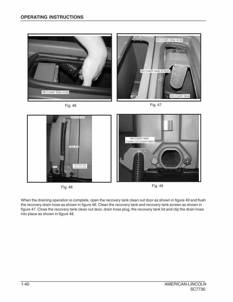
When the draining operation is complete, open the recovery tank clean out door as shown in figure 49 and flush
the recovery drain hose as shown in figure 46. Clean the recovery tank and recovery tank screen as shown in
figure 47. Close the recovery tank clean out door, drain hose plug, the recovery tank lid and clip the drain hose
into place as shown in figure 48.
Fig. 46 Fig. 47
Fig. 48 Fig. 49
OPERATING INSTRUCTIONS
AMERICAN-LINCOLN 1-41
SC7730
OPERATING INSTRUCTIONS
DISK SCRUB BRUSHESDISK SCRUB BRUSH
MAIN BROOM
SIDE BROOM
Fig. 50 Fig. 51
Fig. 52 Fig. 53
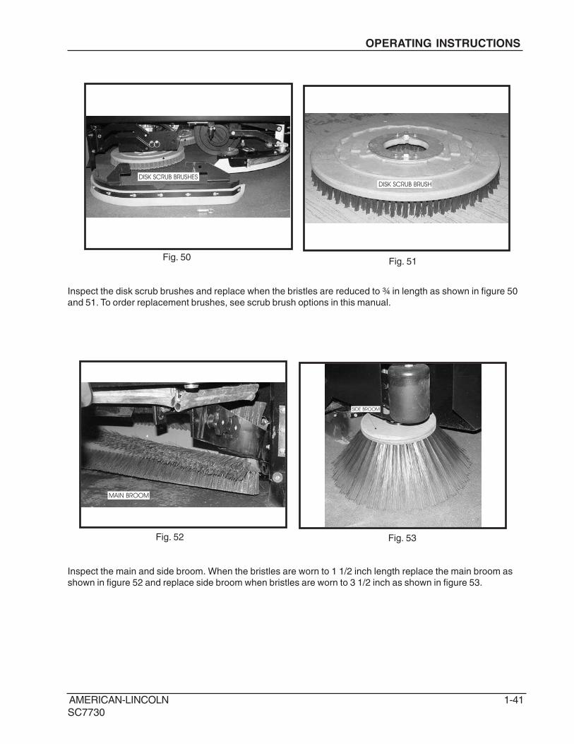
Inspect the disk scrub brushes and replace when the bristles are reduced to ¾ in length as shown in figure 50
and 51. To order replacement brushes, see scrub brush options in this manual.
Inspect the main and side broom. When the bristles are worn to 1 1/2 inch length replace the main broom as
shown in figure 52 and replace side broom when bristles are worn to 3 1/2 inch as shown in figure 53.
1-42 AMERICAN-LINCOLN
SC7730
OPERATING INSTRUCTIONS
REAR SQUEEGEE
TOP OR REAR SQUEEGEE
BOTTOM OF REAR SQUEEGEE
SIDE SQUEEGEE
Fig. 54 Fig. 55
Fig. 56
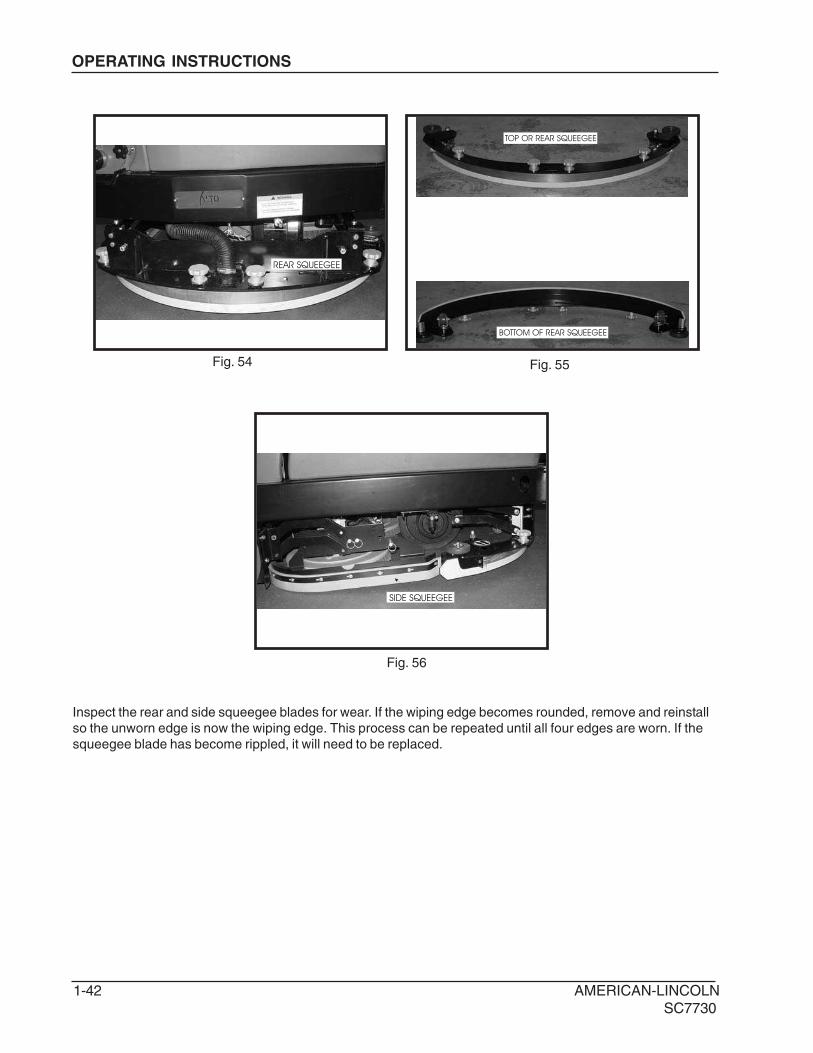
Inspect the rear and side squeegee blades for wear. If the wiping edge becomes rounded, remove and reinstall
so the unworn edge is now the wiping edge. This process can be repeated until all four edges are worn. If the
squeegee blade has become rippled, it will need to be replaced.
AMERICAN-LINCOLN 1-43
SC7730
DUST CONTROL
KNOB
DUST CONTROL
PANEL FILTER
Fig. 57 Fig. 58
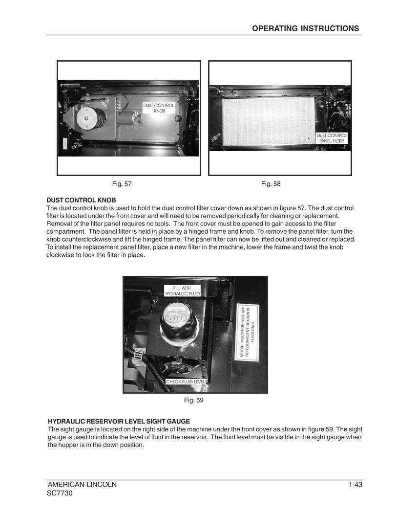
DUST CONTROL KNOB
The dust control knob is used to hold the dust control filter cover down as shown in figure 57. The dust control
filter is located under the front cover and will need to be removed periodically for cleaning or replacement.
Removal of the filter panel requires no tools. The front cover must be opened to gain access to the filter
compartment. The panel filter is held in place by a hinged frame and knob. To remove the panel filter, turn the
knob counterclockwise and lift the hinged frame. The panel filter can now be lifted out and cleaned or replaced.
To install the replacement panel filter, place a new filter in the machine, lower the frame and twist the knob
clockwise to lock the filter in place.
FILL WITH
HYDRAULIC FLUID
CHECK FLUID LEVEL
HYDRAULIC RESERVOIR LEVEL SIGHT GAUGE
The sight gauge is located on the right side of the machine under the front cover as shown in figure 59. The sight
gauge is used to indicate the level of fluid in the reservoir. The fluid level must be visible in the sight gauge when
the hopper is in the down position.
Fig. 59
OPERATING INSTRUCTIONS
1-44 AMERICAN-LINCOLN
SC7730
SERVICE CHART
Check items for proper operation. If service is required, please contact an authorized American-Lincoln
Technology distributor. For best performance, replace worn parts with genuine American-Lincoln parts.
EVERY eight (8) HOURS or DAILY check and clean/adjust if necessary:
1 Inspect panel filter for damage and clean them.
2 Inspect and clean hopper.
3 Inspect and clean recovery tank screens and filters.
4 Check hydraulic fluid level.
5 Check all flaps for wear or damage.
6 Check brooms for wear or damage, adjust as required.
7 Check brake pedal and parking brake.
8 Check hydraulic oil filter.
9 Check battery electrolyte level.
10 Check all fluid system components for leaks.
50 HOUR (WEEKLY) MAINTENANCE CHECKLIST
11 Check solution tank (recycling or ESP system).
12 Check solution filter screen (recycling or ESP system).
13 Check recovery tank.
14 Check recovery tank screens and filters.
15 Inspect scrub brushes for wear or damage.
16 Inspect rear and side squeegees for wear or damage.
17 Check battery electrolyte level.
18 Check all hydraulic hoses for wear or cuts.
19 Rotate main brush.
20 Clean or replace panel filter.
21 Lubricate squeegee casters.
100 HOUR MAINTENANCE CHECKLIST
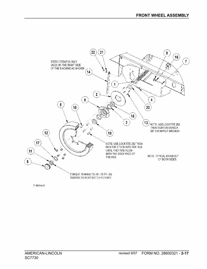
22 Lubricate front wheel bearings.
23 Lubricate all moving joints.
250 HOUR MAINTENANCE CHECKLIST
24 Lubricate squeegee casters.
25 Clean solution tank and filter screen.
26 Replace hydraulic filter element.
27 Clean hydraulic reservoir.
MAINTENANCE
AMERICAN-LINCOLN 1-45
SC7730
MAINTENANCE
3, 13, 1411, 12, 25
5, 6 4, 8,
26, 27
5, 19
21, 24
7 9, 17 181, 20
6
1615 16
5 22, 23
6
2
1-46 AMERICAN-LINCOLN
SC7730
MAINTENANCE
For safety, read and follow the service precautions below. Know the hazards associated with the equipment
you are working on to prevent personal injury or damage to equipment.
For service assistance, consult your nearest American-Lincoln dealer. For best performance replace worn
parts with genuine American-Lincoln parts.
Refer all maintenance and service requirements to qualified maintenance personnel.
DO NOT attempt to service this machine until you have read and understand all safety warnings associated
with the equipment you are working on.
WARNING
• Maintenance and repairs must be done by authorized personnel only.
••••• Electrical repairs must be done by authorized personnel only. Consult your American-Lincoln
Authorized Service Person to do service procedures. Use only genuine American-Lincoln
parts.
••••• Always park on a level surface, turn key off, and engage parking brake before working on
the machine to keep it from creeping or rolling.
••••• Maintenance and repairs must be done by authorized personnel only. Always empty thesolution tank and the recovery tank before doing any maintenance. Keep all fasteners tight.Keep adjustments according to the specifications as shown in the Service Manual for thismachine.
••••• Always wear eye protection and protective clothing when working near batteries. Do not puttools or other metal objects across the topes of the batteries. NO SMOKING.
••••• To prevent damage to the machine, and discharge across the tops of the batteries, do not fillthe batteries above the bottom of the tube in each cell. Wipe any acid from the machine orthe tops of the batteries. Do not add acid to a battery after installation.
••••• The hopper could fall and cause serious injury. Always engage the hopper safety arm before
working under the hopper.
••••• To maintain the stability of this machine in normal operation, the overhead guard, or similar
equipment installed by the manufacturer as original equipment should not be removed. If it
becomes necessary to remove such equipment for repair or maintenance, this equipment
must be reinstalled before machine is placed back in operation.
AMERICAN-LINCOLN 1-47
SC7730
MAINTENANCE
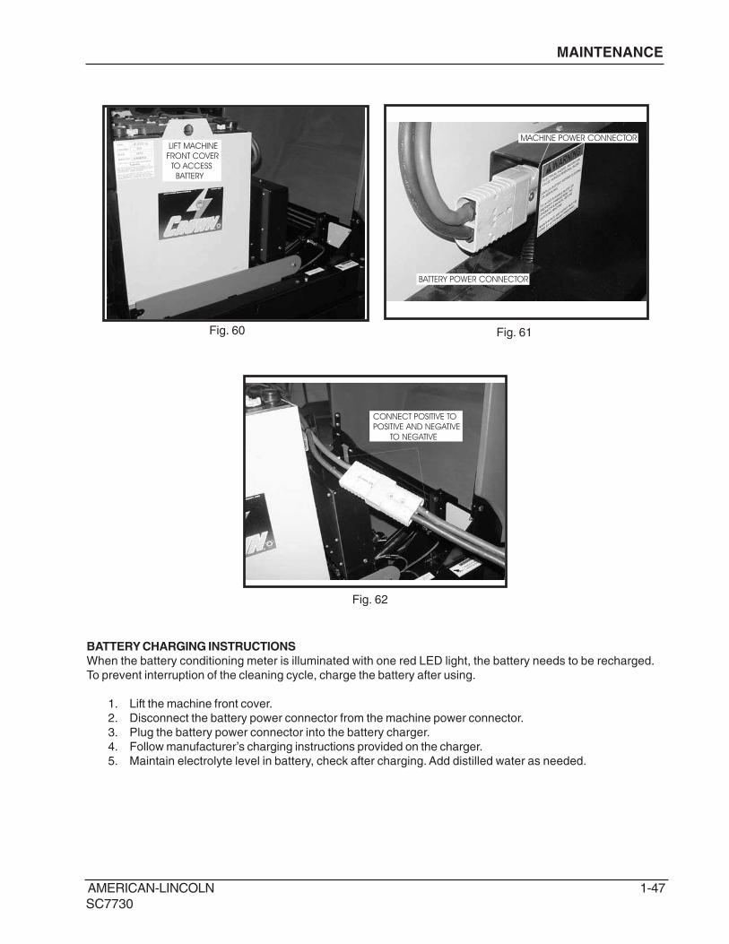
MACHINE POWER CONNECTOR
BATTERY POWER CONNECTOR
BATTERY CHARGING INSTRUCTIONS
When the battery conditioning meter is illuminated with one red LED light, the battery needs to be recharged.
To prevent interruption of the cleaning cycle, charge the battery after using.
1. Lift the machine front cover.
2. Disconnect the battery power connector from the machine power connector.
3. Plug the battery power connector into the battery charger.
4. Follow manufacturer’s charging instructions provided on the charger.
5. Maintain electrolyte level in battery, check after charging. Add distilled water as needed.
Fig. 60 Fig. 61
Fig. 62
LIFT MACHINE
FRONT COVER
TO ACCESS
BATTERY
CONNECT POSITIVE TO
POSITIVE AND NEGATIVE
TO NEGATIVE
1-48 AMERICAN-LINCOLN
SC7730
BATTERY REMOVALWhen removing batteries
1. Lift the machine front cover to access battery compartment.2. Unplug the battery power connector from the machine power connector.3. Rotate the battery lever to the right.4. Lift the battery out using a 2000 LB. (907 KG) capacity lifting device.
BATTERY LEVER
CONNECT A 2000 LB. (907 KG)
CAPACITY LIFTING DEVICE
Fig. 63 Fig. 64
Fig. 65
CONNECTING BATTERY
MAINTENANCE
WARNING• Do not remove the battery from the machine if there is waste in the solution tank.
••••• Hydrogen gas is formed during the charging operation and is explosive! Only chargebatteries in a well-ventilated area with the lid open. Avoid any open flame or electricalsparks. Pulling out the charger plug, with the charger still on, will cause an arc and must beavoided.
••••• Batteries are heavy. Use lifting device with specified rated capacity.
••••• Always remove jewelry, wear protective clothing, and face protection when working nearbatteries.
••••• Lead acid batteries generate gases, which cause explosions. Keep sparks and flames awayfrom batteries charge the batteries only in area with good ventilation. NO SMOKING!
••••• To prevent an explosion, disconnect the AC plug from the receptacle before connection ordisconnect the DC plug on the charger.
••••• The battery box can slide off a forklift and cause severe personal injury or damage toequipment. Ensure that the battery box is properly secured to the forks of the forklift duringtransport, drive and stop with caution.
BATTERY COMPARTMENT
Fig. 66
AMERICAN-LINCOLN 1-49
SC7730
MAINTENANCE
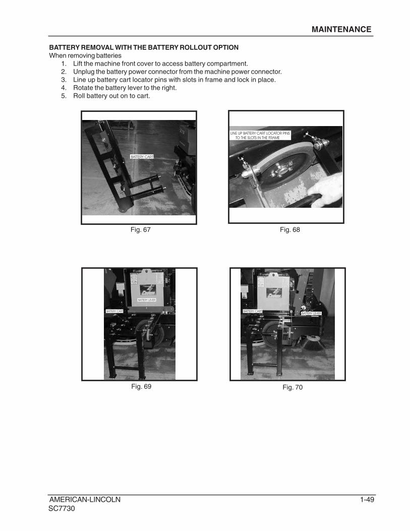
BATTERY REMOVAL WITH THE BATTERY ROLLOUT OPTION
When removing batteries
1. Lift the machine front cover to access battery compartment.
2. Unplug the battery power connector from the machine power connector.
3. Line up battery cart locator pins with slots in frame and lock in place.
4. Rotate the battery lever to the right.
5. Roll battery out on to cart.
BATTERY CART
LINE UP BATTERY CART LOCATOR PINS
TO THE SLOTS IN THE FRAME
BATTERY CART
BATTERY LEVER
BATTERY CARTBATTERY LEVER
Fig. 67
Fig. 70Fig. 69
Fig. 68
1-50 AMERICAN-LINCOLN
SC7730
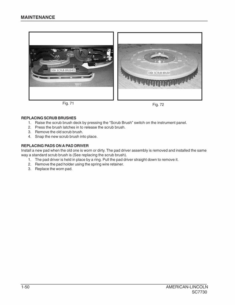
REPLACING SCRUB BRUSHES
1. Raise the scrub brush deck by pressing the “Scrub Brush” switch on the instrument panel.
2. Press the brush latches in to release the scrub brush.
3. Remove the old scrub brush.
4. Snap the new scrub brush into place.
REPLACING PADS ON A PAD DRIVER
Install a new pad when the old one is worn or dirty. The pad driver assembly is removed and installed the sameway a standard scrub brush is (See replacing the scrub brush).
1. The pad driver is held in place by a ring. Pull the pad driver straight down to remove it.
2. Remove the pad holder using the spring wire retainer.
3. Replace the worn pad.
DISK SCRUB BRUSHESDISK SCRUB BRUSH
Fig. 71 Fig. 72
MAINTENANCE
AMERICAN-LINCOLN 1-51
SC7730
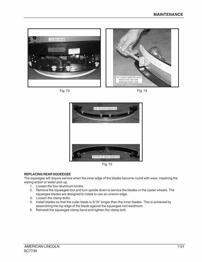
LOOSEN KNOB
TOP OR REAR SQUEEGEE
BOTTOM OF REAR SQUEEGEE
REPLACING REAR SQUEEGEE
The squeegee will require service when the inner edge of the blades become round with wear, impairing the
wiping action or water pick up.
1. Loosen the four aluminum knobs.
2. Remove the squeegee tool and turn upside down to service the blades or the caster wheels. The
squeegee blades are designed to rotate to use an unworn edge.
3. Loosen the clamp bolts.
4. Install blades so that the outer blade is 3/16" longer than the inner blades. This is achieved by
assembling the top edge of the blade against the squeegee tool weldment.
5. Reinstall the squeegee clamp band and tighten the clamp bolt.
TO CHANGE SQUEEGEE BLADE
REMOVE NUT AND TURN
SQUEEGEE BLADE OVER
Fig. 73
Fig. 75
Fig. 74
MAINTENANCE
1-52 AMERICAN-LINCOLN
SC7730
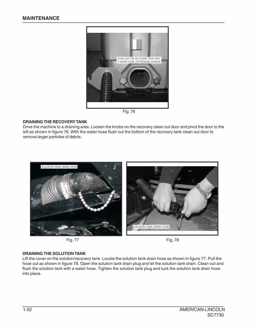
DRAINING THE RECOVERY TANK
Drive the machine to a draining area. Loosen the knobs on the recovery clean out door and pivot the door to the
left as shown in figure 76. With the water hose flush out the bottom of the recovery tank clean out door to
remove larger particles of debris.
MAINTENANCE
FLUSH OUT THE RECOVERY TANK WITH
A WATER HOSE OR PRESSURE WASHER
SOLUTION TANK DRAIN HOSE
SOLUTION TANK DRAIN HOSE
DRAINING THE SOLUTION TANK
Lift the cover on the solution/recovery tank. Locate the solution tank drain hose as shown in figure 77. Pull the
hose out as shown in figure 78. Open the solution tank drain plug and let the solution tank drain. Clean out and
flush the solution tank with a water hose. Tighten the solution tank plug and tuck the solution tank drain hose
into place.
Fig. 76
Fig. 77 Fig. 78
AMERICAN-LINCOLN 1-53
SC7730
MAINTENANCE
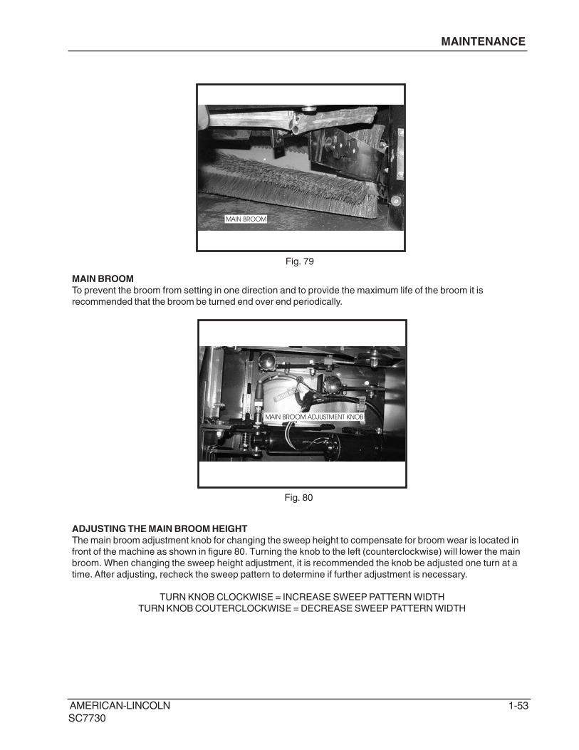
MAIN BROOM
MAIN BROOM
To prevent the broom from setting in one direction and to provide the maximum life of the broom it is
recommended that the broom be turned end over end periodically.
ADJUSTING THE MAIN BROOM HEIGHT
The main broom adjustment knob for changing the sweep height to compensate for broom wear is located in
front of the machine as shown in figure 80. Turning the knob to the left (counterclockwise) will lower the main
broom. When changing the sweep height adjustment, it is recommended the knob be adjusted one turn at a
time. After adjusting, recheck the sweep pattern to determine if further adjustment is necessary.
The Main Broom should be replaced when the bristles become worn to less than 1 1/2”. The main broom is
held in place by the right side broom door. This feature provides for easy removal and installation of the main
broom without the need for special tools or equipment. Lift the hopper to gain access to the main broom
compartment. Loosen the main broom access door knob and open the main broom access door. Rotate and
remove the broom lift arm knobs counterclockwise to the left as shown in figure 82 and 83.
MAIN BROOM ACCESS DOOR
The main broom access door is located in front of the left side tire of the machine as shown in figure 81. The
door provides access to the main broom for service or inspection. The hopper must be raised to access.
WARNINGEngage hopper safety arm while accessing the main broom
AMERICAN-LINCOLN 1-55
SC7730
SLIDE BROOM ONTO
BROOM IDLER
REMOVE BROOM LIFT ARM
MAINTENANCE
BROOM LIFT ARM
BROOM IDLER
BROOM IDLER
Fig. 84 Fig. 85
Fig. 86 Fig. 87
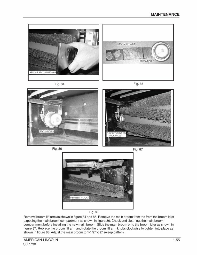
Remove broom lift arm as shown in figure 84 and 85. Remove the main broom from the from the broom idler
exposing the main broom compartment as shown in figure 86. Check and clean out the main broom
compartment before installing the new main broom. Slide the main broom onto the broom idler as shown in
figure 87. Replace the broom lift arm and rotate the broom lift arm knobs clockwise to tighten into place as
shown in figure 88. Adjust the main broom to 1-1/2” to 2” sweep pattern.
INSTALLED BROOM
Fig. 88
1-56 AMERICAN-LINCOLN
SC7730
SIDE BROOM ADJUSTMENT KNOB
MAINTENANCE
SIDE BROOM
The side broom (Fig. 89) sweeping angle is not
adjustable. However, the height of the side
broom can be adjusted to compensate as the
broom becomes worn from use. Always check
and adjust the sweep pattern after changing the
side broom.
ADJUSTING THE SIDE BROOM HEIGHT
Turn the side broom adjustment knob (Fig. 90)
to change the side broom sweep height.
Recheck for proper sweep pattern after
adjustment.
Turn the adjustment knob counterclockwise to
INCREASE the sweep pattern width.
Turn the adjustment knob clockwise to
DECREASE the sweep pattern width.
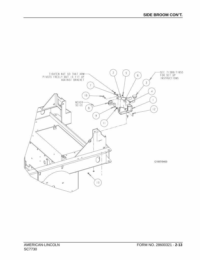
REPLACING THE SIDE BROOM
Change the side broom (Fig. 91) when the
bristles become worn to less than 3 inches
length.
1. Park the machine on a smooth level
surface, turn key switch to “O” Position and
engage parking brake.
2. Place the side brooms switch in the “UP”
position.
3. Remove the lock pin that holds the broom
flange to the motor shaft.
4. Disassemble the flange from the broom by
removing the screws that hold the flange to
the broom.
5. Assemble the flange to the replacement
broom and fasten using the hardware
removed.
6. Install the replacement broom on the shaft
and insert the lock pin.
Fig. 89
Fig. 90
Fig. 91
AMERICAN-LINCOLN 1-57
SC7730
MAINTENANCE
HOPPER
Fig. 92 Fig. 93
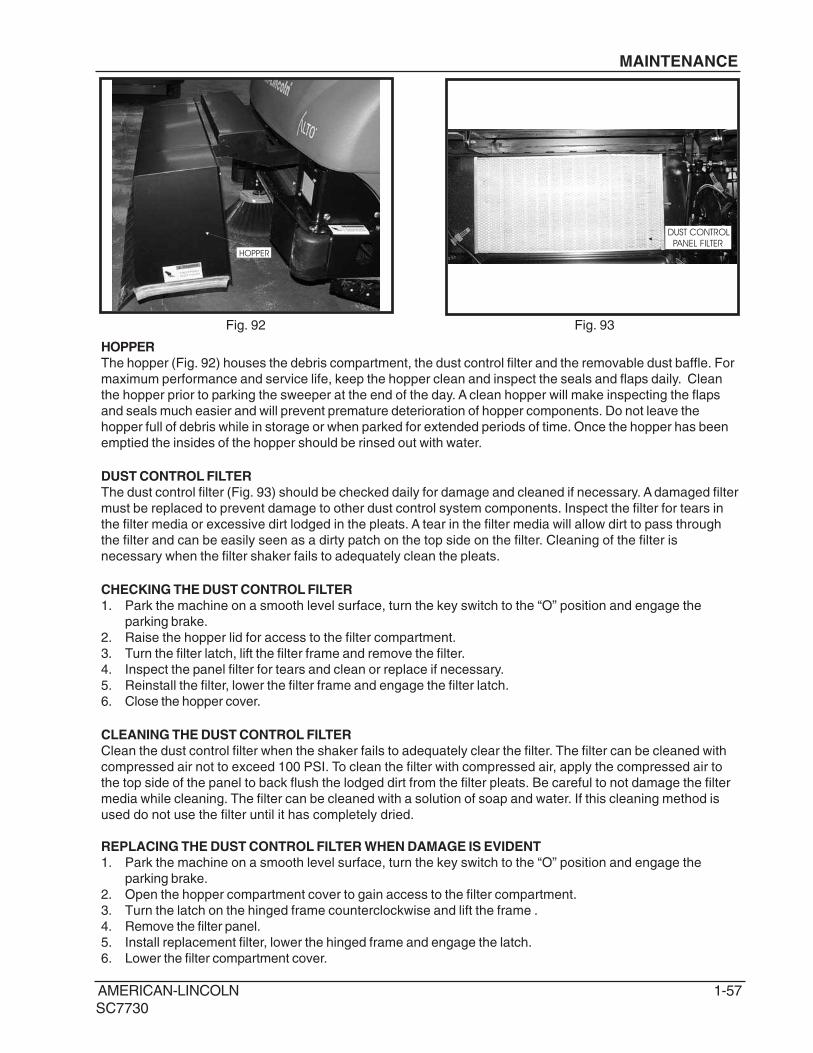
HOPPER
The hopper (Fig. 92) houses the debris compartment, the dust control filter and the removable dust baffle. For
maximum performance and service life, keep the hopper clean and inspect the seals and flaps daily. Clean
the hopper prior to parking the sweeper at the end of the day. A clean hopper will make inspecting the flaps
and seals much easier and will prevent premature deterioration of hopper components. Do not leave the
hopper full of debris while in storage or when parked for extended periods of time. Once the hopper has been
emptied the insides of the hopper should be rinsed out with water.
DUST CONTROL FILTER
The dust control filter (Fig. 93) should be checked daily for damage and cleaned if necessary. A damaged filter
must be replaced to prevent damage to other dust control system components. Inspect the filter for tears in
the filter media or excessive dirt lodged in the pleats. A tear in the filter media will allow dirt to pass through
the filter and can be easily seen as a dirty patch on the top side on the filter. Cleaning of the filter is
necessary when the filter shaker fails to adequately clean the pleats.
CHECKING THE DUST CONTROL FILTER
1. Park the machine on a smooth level surface, turn the key switch to the “O” position and engage the
parking brake.
2. Raise the hopper lid for access to the filter compartment.
3. Turn the filter latch, lift the filter frame and remove the filter.
4. Inspect the panel filter for tears and clean or replace if necessary.
5. Reinstall the filter, lower the filter frame and engage the filter latch.
6. Close the hopper cover.
CLEANING THE DUST CONTROL FILTER
Clean the dust control filter when the shaker fails to adequately clear the filter. The filter can be cleaned with
compressed air not to exceed 100 PSI. To clean the filter with compressed air, apply the compressed air to
the top side of the panel to back flush the lodged dirt from the filter pleats. Be careful to not damage the filter
media while cleaning. The filter can be cleaned with a solution of soap and water. If this cleaning method is
used do not use the filter until it has completely dried.
REPLACING THE DUST CONTROL FILTER WHEN DAMAGE IS EVIDENT
1. Park the machine on a smooth level surface, turn the key switch to the “O” position and engage the
parking brake.
2. Open the hopper compartment cover to gain access to the filter compartment.
3. Turn the latch on the hinged frame counterclockwise and lift the frame .
4. Remove the filter panel.
5. Install replacement filter, lower the hinged frame and engage the latch.
6. Lower the filter compartment cover.
DUST CONTROL
PANEL FILTER
1-58 AMERICAN-LINCOLN
SC7730
DUST FLAPSThe dust flaps are very important to sweeping and dust control and are susceptible to damage and should beinspected daily and maintained in good condition.
CHECKING THE DUST FLAPSThe dust flaps are used on the wheel well, broom chamber and broom door. Inspect the flaps daily and replaceany flap that shows signs of wear or deterioration. All flaps should be replaced when worn or damaged to thepoint that they can no longer perform their normal function. The adjustable flaps have slotted mounting holes tofacilitate adjustment.
ADJUSTING THE DUST FLAPSAdjust the flaps so there is a 1/8" to 1/16" gap between the floor and the bottom edge of the flaps. The rearflapadjustment is 1/16" (16 cm.) above the floor.1. Park the machine on a smooth level surface and engage the parking brake.2. Loosen the flap retaining screws and adjust the flap to clear the floor and leave a 1/16" to 1/8" gap.3. Tighten flap retaining screws while holding flap in position.4. Drive the machine on a smooth surface and recheck the flaps for proper floor clearance.
MAINTENANCE
FILL WITH
HYDRAULIC FLUID
CHECK FLUID LEVEL
Fig. 94
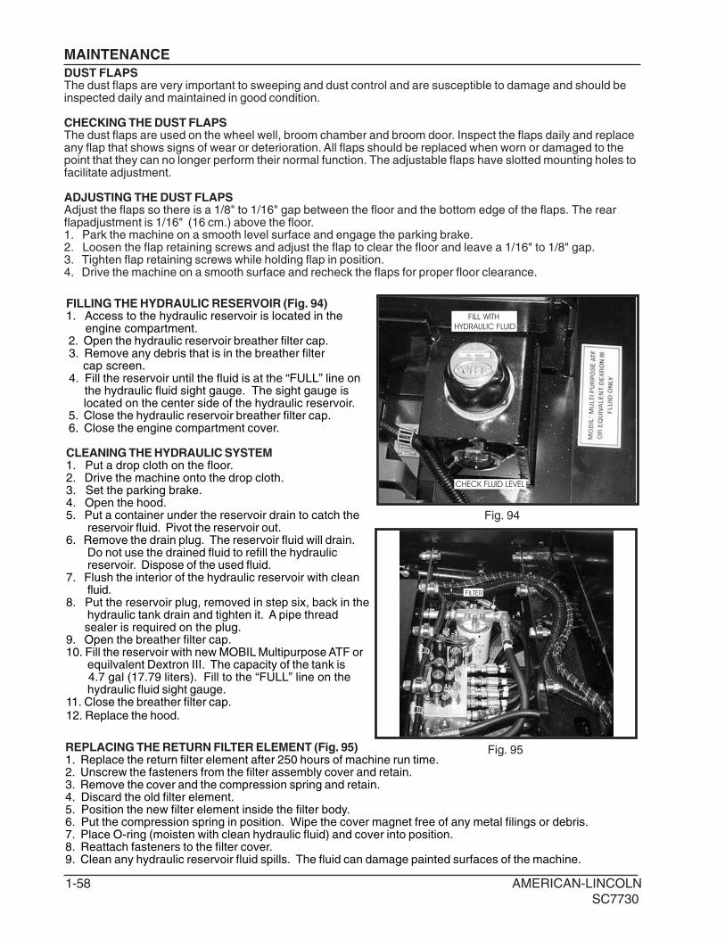
FILLING THE HYDRAULIC RESERVOIR (Fig. 94)1. Access to the hydraulic reservoir is located in the engine compartment. 2. Open the hydraulic reservoir breather filter cap. 3. Remove any debris that is in the breather filter cap screen. 4. Fill the reservoir until the fluid is at the “FULL” line on the hydraulic fluid sight gauge. The sight gauge is located on the center side of the hydraulic reservoir. 5. Close the hydraulic reservoir breather filter cap. 6. Close the engine compartment cover.
CLEANING THE HYDRAULIC SYSTEM1. Put a drop cloth on the floor.2. Drive the machine onto the drop cloth.3. Set the parking brake.4. Open the hood.5. Put a container under the reservoir drain to catch the
reservoir fluid. Pivot the reservoir out.6. Remove the drain plug. The reservoir fluid will drain.
Do not use the drained fluid to refill the hydraulicreservoir. Dispose of the used fluid.
7. Flush the interior of the hydraulic reservoir with cleanfluid.
8. Put the reservoir plug, removed in step six, back in thehydraulic tank drain and tighten it. A pipe thread
sealer is required on the plug.9. Open the breather filter cap.10. Fill the reservoir with new MOBIL Multipurpose ATF or
equilvalent Dextron III. The capacity of the tank is 4.7 gal (17.79 liters). Fill to the “FULL” line on the
hydraulic fluid sight gauge.11. Close the breather filter cap.12. Replace the hood.
FILTER
REPLACING THE RETURN FILTER ELEMENT (Fig. 95)1. Replace the return filter element after 250 hours of machine run time.2. Unscrew the fasteners from the filter assembly cover and retain.3. Remove the cover and the compression spring and retain.4. Discard the old filter element.5. Position the new filter element inside the filter body.6. Put the compression spring in position. Wipe the cover magnet free of any metal filings or debris.7. Place O-ring (moisten with clean hydraulic fluid) and cover into position.8. Reattach fasteners to the filter cover.9. Clean any hydraulic reservoir fluid spills. The fluid can damage painted surfaces of the machine.
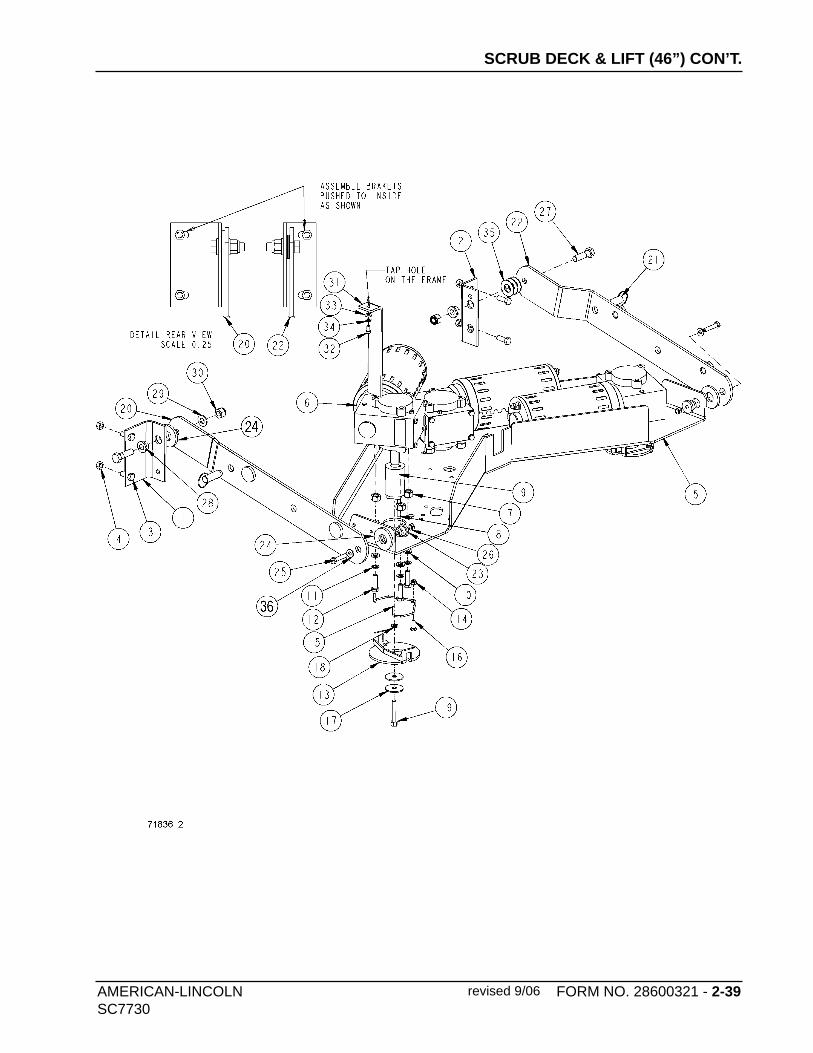
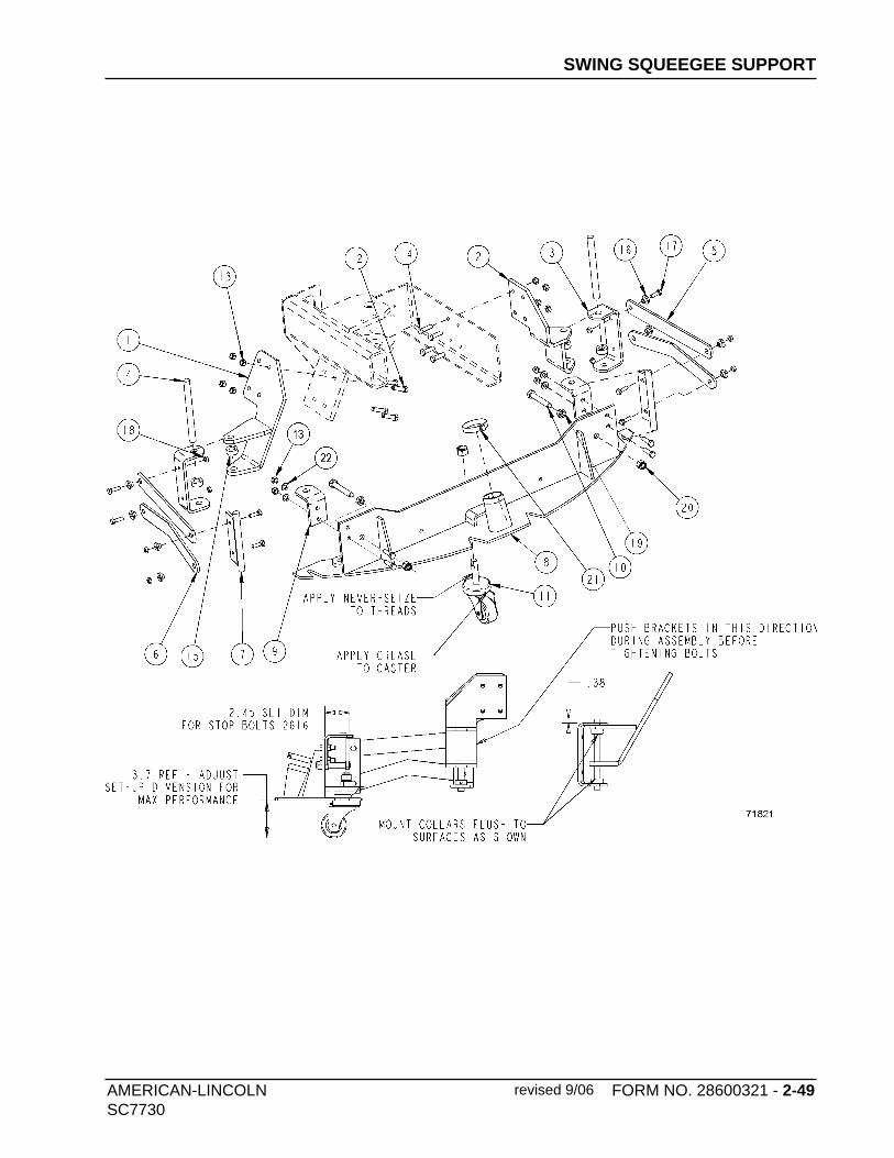
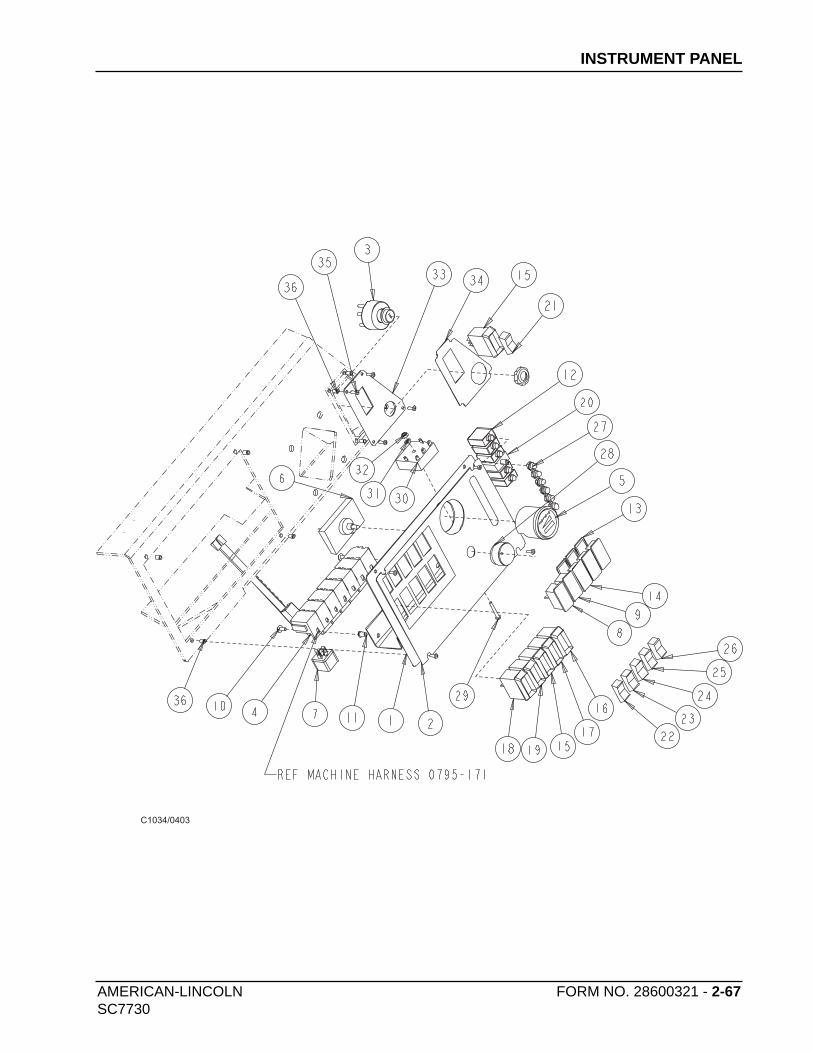
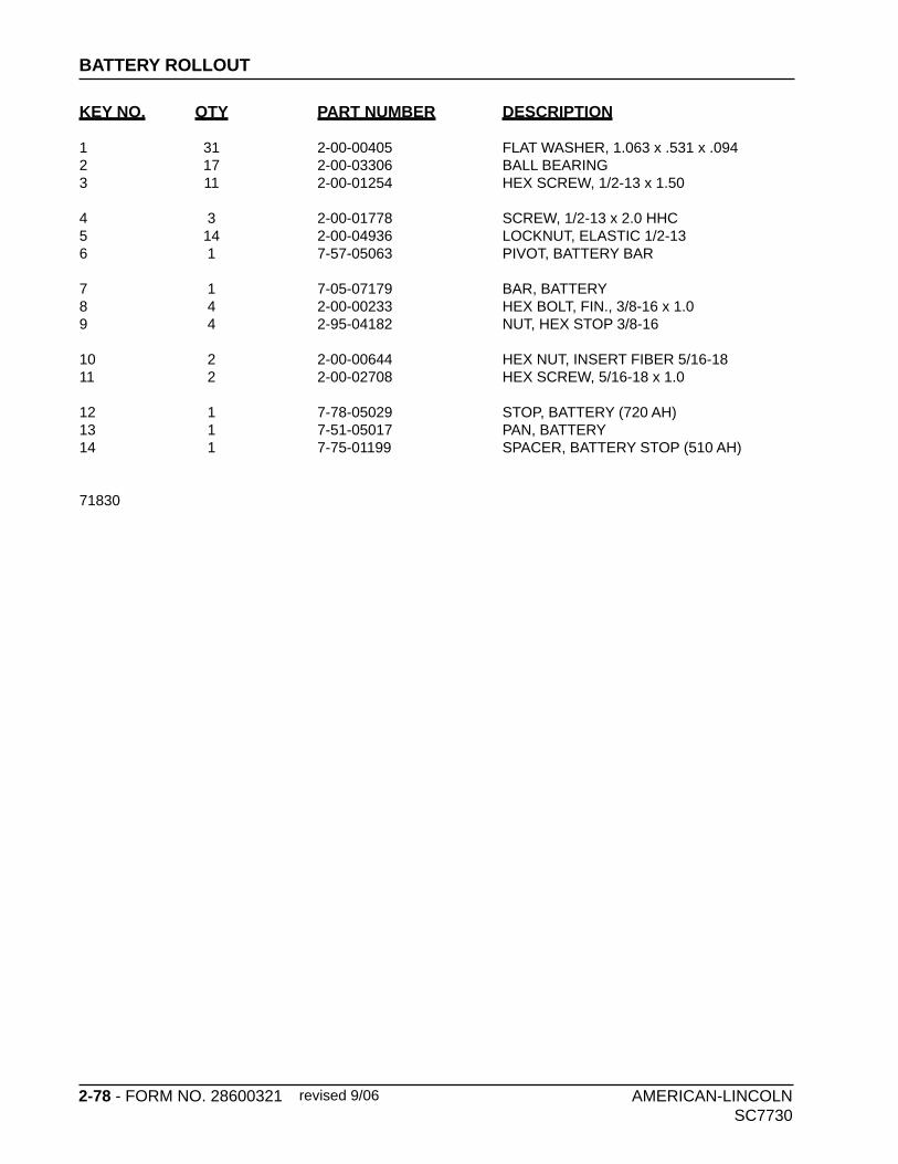
29 1 7-25-02033 PLUG, HOSE30 1 2-00-03466 SCREW , #10-16 x 1/231 2 7-31-07032 HANGER, DRAIN HOSE32 4 2-00-04876 SCREW, 1/4-20 x .50 BHCS W/NYLOK33 8 2-00-01994 SCREW, #8-15 x 3/4 LG, TF/PRH34 4 7-29-00281 GASKET35 4 2-00-03702 WASHER, .625 x .281 x .063
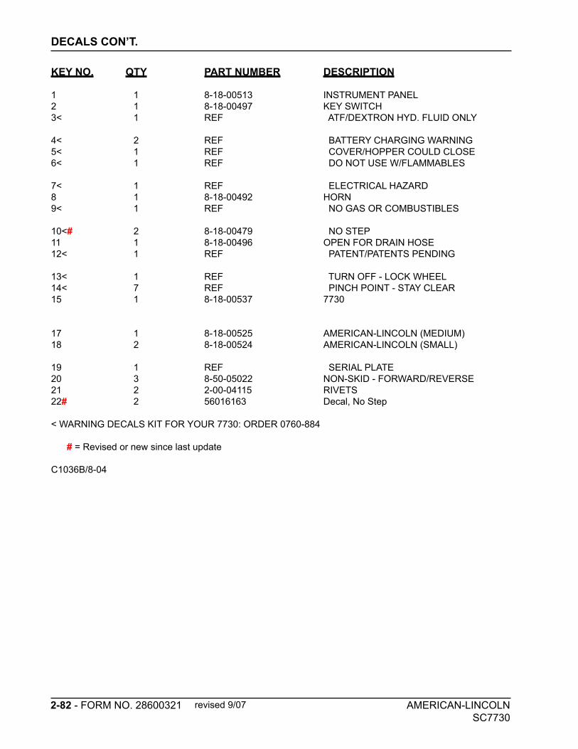
*IF REPLACING ITEM #1, YOU MUST ALSO ORDER: 1 OF 8-18-00537 (7730 DECAL) 1 OF 8-18-00524 (AMERICAN-LINCOLN LOGO DECAL) (REFERENCE PAGE 2-80 THRU 2-83 FOR PLACE MENT)
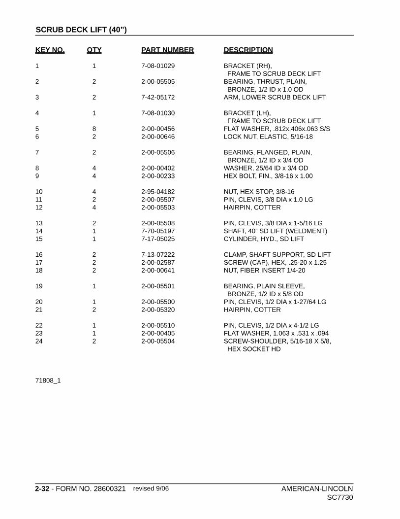
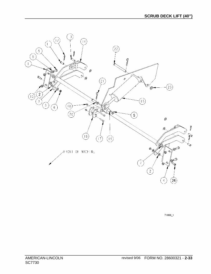
19 1 2-00-05501 BEARING, PLAIN SLEEVE, BRONZE, 1/2 ID x 5/8 OD 20 1 2-00-05500 PIN, CLEVIS, 1/2 DIA x 1-27/64 LG21 2 2-00-05320 HAIRPIN, COTTER
22 1 2-00-05510 PIN, CLEVIS, 1/2 DIA x 4-1/2 LG23 1 2-00-00405 FLAT WASHER, 1.063 x .531 x .09424 2 2-00-05504 SCREW-SHOULDER, 5/16-18 X 5/8, HEX SOCKET HD
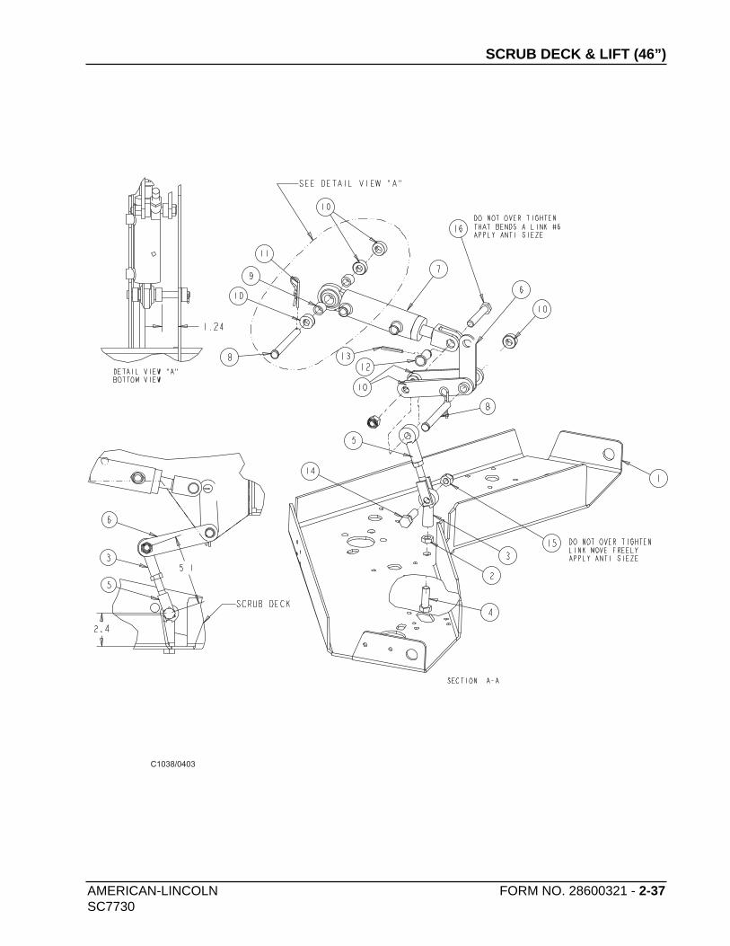
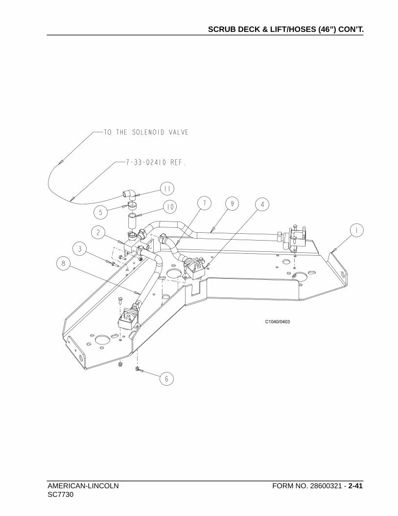
5 1 7-42-05179 LINK, DECK LIFT6 1 7-03-04234 ARM, SCRUB DECK LIFT (WELDMENT)7 1 7-17-05020 CYLINDER, HOPPER DOOR8 2 2-00-05510 PIN, CLEVIS, 1/2 DIA x 4 1/2 LG
9 2 2-00-03151 SPACER, 1/2 ID x 3/4 OD x 5/8 LG10 6 2-00-03589 COLLAR11 2 2-00-05320 HAIRPIN, COTTER12 1 7-55-08169 PIN, .625 DIA x 1-1/4 (w/HAIRPIN COTTER)
13 1 2-00-00775 COTTER PIN, 1/8 DIA x 1 LG14 1 2-00-00241 BOLT 1/2-13 x 1-3/4 LG15 2 2-00-04936 LOCKNUT, ELASTIC, 1/2-1316 1 2-00-02616 HEX BOLT, FIN., 1/2-13 x 3.00
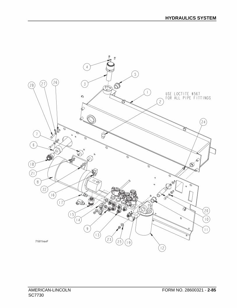
13 8 2-00-04918 FITTING, -6 SAE x -4 ORS, STR. 14 2 2-00-05340 Fitting, HYD., 9/16-18 ORF x 9/16-18 ST, 45 Elbow15 1 2-00-05914 FITTING, 12-8 ORFS-ORB 16 2 2-00-05435 FITTING, 90 ORFS TO ORS BOSS 06 x 06
17 1 2-00-05442 Fitting, ORFS M TO ORS M BOSS 06 X 0618 1 2-00-05387 FITTING, STR #12 ORS x 3/4-14 NPT 19 1 2-00-05217 FITTING, 90 ELBOW ORFS M TO NPTF M 08 x 1220 4 2-00-00530 LOCK WASHER 5/16”