44
OPERATOR'S MANUAL Model 60/62 Shake Freezers Original Operating Instructions 051059-M 4/00 (Original Publication) Updated 3/23/16

OPERATOR'SMANUAL
Model 60/62Shake Freezers
Original Operating Instructions
051059-M4/00 (Original Publication)
Updated 3/23/16

Complete this page for quick reference when service is required:
Taylor Distributor:
Address:
Phone:
Service:
Parts:
Date of Installation:
Information found on the data label:
Model Number:
Serial Number:
Electrical Specs: Voltage Cycle
Phase
Maximum Fuse Size: A
Minimum Wire Ampacity: A
E 2000 Carrier Commercial Refrigeration, Inc.051059-M
Any unauthorized reproduction, disclosure, or distribution of copies by any person of any portion of this work may bea violation of Copyright Law of the United States of America and other countries, could result in the awarding of StatutoryDamages of up to $250,000 (17 USC 504) for infringement, and may result in further civil and criminal penalties. Allrights reserved.
Taylor Companya division of Carrier Commercial Refrigeration, Inc.750 N. Blackhawk Blvd.Rockton, IL 61072

Table of Contents Models 60 & 62
Table of Contents
Section 1 To the Installer 1. . . . . . . . . . . . . . . . . . . . . . . . . . . . . . . . . . . . . . . . . . . .
Installer Safety 1. . . . . . . . . . . . . . . . . . . . . . . . . . . . . . . . . . . . . . . . . . . . . . . . . . . . . . . .
Site Preparation 1. . . . . . . . . . . . . . . . . . . . . . . . . . . . . . . . . . . . . . . . . . . . . . . . . . . . . . .
Water Connections (Water Cooled Units Only) 2. . . . . . . . . . . . . . . . . . . . . . . . . . . .
Air Cooled Units 2. . . . . . . . . . . . . . . . . . . . . . . . . . . . . . . . . . . . . . . . . . . . . . . . . . . . . . .
Electrical Connections 2. . . . . . . . . . . . . . . . . . . . . . . . . . . . . . . . . . . . . . . . . . . . . . . . .
Beater Rotation 3. . . . . . . . . . . . . . . . . . . . . . . . . . . . . . . . . . . . . . . . . . . . . . . . . . . . . . .
Refrigerant 3. . . . . . . . . . . . . . . . . . . . . . . . . . . . . . . . . . . . . . . . . . . . . . . . . . . . . . . . . . .
Section 2 To the Operator 4. . . . . . . . . . . . . . . . . . . . . . . . . . . . . . . . . . . . . . . . . . .
Compressor Warranty Disclaimer 4. . . . . . . . . . . . . . . . . . . . . . . . . . . . . . . . . . . . . . .
Section 3 Safety 5. . . . . . . . . . . . . . . . . . . . . . . . . . . . . . . . . . . . . . . . . . . . . . . . . . . .Section 4 Operator Parts Identification 7. . . . . . . . . . . . . . . . . . . . . . . . . . . . . . .Section 5 Important: To the Operator 11. . . . . . . . . . . . . . . . . . . . . . . . . . . . . . . . .
Control Switch 11. . . . . . . . . . . . . . . . . . . . . . . . . . . . . . . . . . . . . . . . . . . . . . . . . . . . . . . .
Dial Light 11. . . . . . . . . . . . . . . . . . . . . . . . . . . . . . . . . . . . . . . . . . . . . . . . . . . . . . . . . . . . .
Indicator Light (“Mix Low”) 11. . . . . . . . . . . . . . . . . . . . . . . . . . . . . . . . . . . . . . . . . . . . . .
Indicator Light (“Mix Out”) 11. . . . . . . . . . . . . . . . . . . . . . . . . . . . . . . . . . . . . . . . . . . . . .
Reset Mechanism 12. . . . . . . . . . . . . . . . . . . . . . . . . . . . . . . . . . . . . . . . . . . . . . . . . . . . .
Consistency Control* 12. . . . . . . . . . . . . . . . . . . . . . . . . . . . . . . . . . . . . . . . . . . . . . . . . .
Spinner Rinse Switch* 12. . . . . . . . . . . . . . . . . . . . . . . . . . . . . . . . . . . . . . . . . . . . . . . . .
Auto Lift Switch (Model 60 Only)* 12. . . . . . . . . . . . . . . . . . . . . . . . . . . . . . . . . . . . . . . .
Foot Pedal (Model 60 Only) 12. . . . . . . . . . . . . . . . . . . . . . . . . . . . . . . . . . . . . . . . . . . .
Flavor Selector Switch* 12. . . . . . . . . . . . . . . . . . . . . . . . . . . . . . . . . . . . . . . . . . . . . . . .
Section 6 Operating Procedures 13. . . . . . . . . . . . . . . . . . . . . . . . . . . . . . . . . . . . .
Assembly 13. . . . . . . . . . . . . . . . . . . . . . . . . . . . . . . . . . . . . . . . . . . . . . . . . . . . . . . . . . . .
Sanitizing 18. . . . . . . . . . . . . . . . . . . . . . . . . . . . . . . . . . . . . . . . . . . . . . . . . . . . . . . . . . . .
Priming 19. . . . . . . . . . . . . . . . . . . . . . . . . . . . . . . . . . . . . . . . . . . . . . . . . . . . . . . . . . . . . .
Syrup System 21. . . . . . . . . . . . . . . . . . . . . . . . . . . . . . . . . . . . . . . . . . . . . . . . . . . . . . . . .
Drawing Product 23. . . . . . . . . . . . . . . . . . . . . . . . . . . . . . . . . . . . . . . . . . . . . . . . . . . . . .

Table of Contents Models 60 & 62
Table of Contents -- Page 2
Closing Procedures 24. . . . . . . . . . . . . . . . . . . . . . . . . . . . . . . . . . . . . . . . . . . . . . . . . . .
Draining Product From The Freezing Cylinder 24. . . . . . . . . . . . . . . . . . . . . . . . . . . .
Rinsing 24. . . . . . . . . . . . . . . . . . . . . . . . . . . . . . . . . . . . . . . . . . . . . . . . . . . . . . . . . . . . . .
Cleaning 25. . . . . . . . . . . . . . . . . . . . . . . . . . . . . . . . . . . . . . . . . . . . . . . . . . . . . . . . . . . . .
Disassembly 25. . . . . . . . . . . . . . . . . . . . . . . . . . . . . . . . . . . . . . . . . . . . . . . . . . . . . . . . . .
Brush Cleaning 26. . . . . . . . . . . . . . . . . . . . . . . . . . . . . . . . . . . . . . . . . . . . . . . . . . . . . . .
Sanitizing Syrup System 26. . . . . . . . . . . . . . . . . . . . . . . . . . . . . . . . . . . . . . . . . . . . . . .
Section 7 Important: Operator Checklist 29. . . . . . . . . . . . . . . . . . . . . . . . . . . . . .
During Cleaning and Sanitizing: 29. . . . . . . . . . . . . . . . . . . . . . . . . . . . . . . . . . . . . . . . .
Troubleshooting Bacterial Count: 29. . . . . . . . . . . . . . . . . . . . . . . . . . . . . . . . . . . . . . . .
Regular Maintenance Checks: 29. . . . . . . . . . . . . . . . . . . . . . . . . . . . . . . . . . . . . . . . . .
Winter Storage 30. . . . . . . . . . . . . . . . . . . . . . . . . . . . . . . . . . . . . . . . . . . . . . . . . . . . . . . .
Section 8 Troubleshooting Guide 31. . . . . . . . . . . . . . . . . . . . . . . . . . . . . . . . . . . .
Section 9 Parts Replacement Schedule 35. . . . . . . . . . . . . . . . . . . . . . . . . . . . . . .
Section 10 Limited Warranty on Equipment 36. . . . . . . . . . . . . . . . . . . . . . . . . . . .
Section 11 Limited Warranty on Parts 38. . . . . . . . . . . . . . . . . . . . . . . . . . . . . . . . .
Note: Continuing research results in steady improvements; therefore, informationin this manual is subject to change without notice.
Note: Only instructions originating from the factory or its authorized translationrepresentative(s) are considered to be the original set of instructions.
E 2000 Carrier Commercial Refrigeration, Inc. (Original Publication)(Updated March, 2016)051059--M
Any unauthorized reproduction, disclosure, or distribution of copies by any person of any portion of thiswork may be a violation of Copyright Law of the United States of America and other countries, could resultin the awarding of Statutory Damages of up to $250,000 (17 USC 504) for infringement, and may resultin further civil and criminal penalties. All rights reserved.
Taylor Companya division of Carrier Commercial Refrigeration, Inc.750 N. Blackhawk Blvd.Rockton, IL 61072

1Models 60 & 62 To the Installer
131108
Section 1 To the Installer
The following information has been included in themanual as safety and regulatory guidelines. Forcomplete installation instructions, please see theInstallation Checklist.
Installer Safety
In all areas of the world, equipment should beinstalled in accordance with existing local codes.Please contact your local authorities if you have anyquestions.
Care should be taken to ensure that all basic safetypractices are followed during the installation andservicing activities related to the installation andservice of Taylor equipment.
S Only authorized Taylor service personnelshould perform installation and repairs onthe equipment.
S Authorized service personnel should consultOSHA Standard 29CFRI910.147 or theapplicable code of the local area for theindustry standards on lockout/tagoutprocedures before beginning any installationor repairs.
S Authorized service personnel must ensurethat the proper PPE is available and wornwhen required during installation andservice.
S Authorized service personnel must removeall metal jewelry, rings, and watches beforeworking on electrical equipment.
The main power supply(s) to the machinemust be disconnected prior to performing any repairs.Failure to follow this instruction may result in personalinjury or death from electrical shock or hazardousmoving parts as well as poor performance or damageto the equipment.
Note: All repairs must be performed by anauthorized Taylor Service Technician.
This unit has many sharp edges that cancause severe injuries.
Site Preparation
Review the area where the unit will be installed beforeuncrating the unit. Make sure that all possible hazardsto the user and the equipment have been addressed.
For Indoor UseOnly: This unit is designed to operateindoors, under normal ambient temperatures of70_-75_F (21_-24_C). The freezer has successfullyperformed in high ambient temperatures of104_(40_C) at reduced capacities.
This unit must NOT be installed in an areawhere a water jet or hose can be used. NEVER use awater jet or hose to rinse or clean the unit. Failure tofollow this instruction may result in electrocution.
This unit must be installed on a level surfaceto avoid the hazard of tipping. Extreme care should betaken in moving this equipment for any reason. Two ormore people are required to safely move this unit.Failure to comply may result in personal injury orequipment damage.
Uncrate the unit and inspect it for damage. Report anydamage to your Taylor Distributor.
This piece of equipment is made in the USA and hasUSA sizes of hardware. All metric conversions areapproximate and vary in size.

2 Models 60 & 62To the Installer
110620
Water Connections(Water Cooled Units Only)
An adequate cold water supply must be provided witha hand shut- off valve. On the underside rear of thebase pan, two 3/8” I.P.S. water connections for inletand outlet have been provided for easy hook- up. 1/2”inside diameter water lines should be connected to themachine. (Flexible lines are recommended, if localcodes permit.) Depending on local water conditions, itmay be advisable to install a water strainer to preventforeign substances from clogging the automatic watervalve. There will be only one water “in” and one water“out” connection. DONOT install a hand shut- off valveon thewater “out” line!Water should always flow in thisorder: first, through theautomaticwater valve; second,through the condenser; and third, through the outletfitting to an open trap drain.
A back flow prevention device is requiredon the incoming water connection side. Pleaserefer to the applicable National, State, and local codesfor determining the proper configuration.
Air Cooled Units
DO NOT obstruct air intake and discharge openings:
Air cooled units require adequate clearance aroundthe sides of the freezer to allow for adequate air flowacross the condenser.
Counter Models: 6” (152 mm) minimum air space onboth sides. It is recommended to place the rear of theunit against the wall to prevent recirculation of warmair.
Console Models: 3” (76 mm) minimum air space oneach side and rear of unit when air deflector isemployed.
Failure to allow adequate clearance can reduce therefrigeration capacity of the freezer and possiblycause permanent damage to the compressor.
Electrical Connections
Each unit requires one power supply for each datalabel on the unit. Check the data label(s) on the freezerfor branch circuit overcurrent protection or fuse, circuitampacity, and other electrical specifications. Refer tothe wiring diagram provided inside the control box forproper power connections.
In the United States, this equipment is intended to beinstalled in accordance with the National ElectricalCode (NEC), ANSI/NFPA 70- 1987. The purpose ofthe NEC code is the practical safeguarding of personsand property from hazards arising from the use ofelectricity. This code contains provisions considerednecessary for safety. Compliance therewith andproper maintenance will result in an installationessentially free from hazard!
In all other areas of the world, equipment should beinstalled in accordance with the existing local codes.Please contact your local authorities.
FOLLOW YOUR LOCAL ELECTRICAL CODES!
CAUTION: THIS EQUIPMENT MUST BEPROPERLY GROUNDED! FAILURE TO DO SOCAN RESULT IN SEVERE PERSONAL INJURYFROM ELECTRICAL SHOCK!
This unit is provided with an equipotentialgrounding lug that is to be properly attached to the rearof the frameby the authorized installer. The installationlocation is marked by the equipotential bondingsymbol (5021 of IEC 60417-1) on both the removablepanel and the equipment’s frame.

3Models 60 & 62 To the Installer
131105
S Stationary appliances which are notequipped with a power cord and a plug oranother device to disconnect the appliancefrom the power source must have an all-poledisconnecting device with a contact gap ofat least 3 mm installed in the externalinstallation.
S Appliances that are permanently connectedto fixed wiring and for which leakagecurrents may exceed 10 mA, particularlywhen disconnected, not used for longperiods, or during initial installation, shallhave protective devices such as a GFI toprotect against the leakage of current andbe installed by authorized personnel to thelocal codes.
S Supply cords used with this unit shall beoil-resistant, sheathed, flexible cable, notlighter than ordinary polychloroprene orother equivalent syntheticelastomer-sheathed cord (Code designation60245 IEC 57) installed with the proper cordanchorage to relieve conductors from strain,including twisting, at the terminals andprotect the insulation of the conductors fromabrasion.
If the supply cord is damaged, it must bereplaced by the manufacturer, its serviceagent, or similarly qualified person, in orderto avoid a hazard.
Beater Rotation
Beater rotation must be clockwise as viewedlooking into the freezing cylinder.
Note: The following procedures must beperformed by an authorized Taylor servicetechnician.
To correct the rotation on a three- phase unit,interchange any two incoming power supply lines atfreezer main terminal block only.
To correct rotation on a single- phase unit, change theleads inside the beater motor. (Follow the diagramprinted on the motor.)
Electrical connections are made directly to theterminal block provided in the main control box.
Refrigerant
In consideration of our environment, Taylorproudly uses only earth friendly HFC refrigerants. TheHFC refrigerant used in this unit is R404A. Thisrefrigerant is generally considered non-toxic andnon-flammable, with an Ozone Depleting Potential(ODP) of zero (0).
However, any gas under pressure is potentiallyhazardous andmust be handled with caution. NEVERfill any refrigerant cylinder completely with liquid.Filling the cylinder to approximately 80% will allow fornormal expansion.
Use only R404A refrigerant that conforms tothe AHRI standard 700 specification. The use of anyother refrigerant may expose users and operators tounexpected safety hazards.
Refrigerant liquid sprayed onto the skin maycause serious damage to tissue. Keep eyes and skinprotected. If refrigerant burns should occur, flushimmediately with cold water. If burns are severe, applyice packs and contact a physician immediately.
Taylor reminds technicians to be cautious ofgovernment laws regarding refrigerant recovery,recycling, and reclaiming systems. If you have anyquestions regarding these laws, please contact thefactory Service Department.
WARNING: R404A refrigerant used inconjunction with polyolester oils is extremely moistureabsorbent. When opening a refrigeration system, themaximum time the system is openmust not exceed 15minutes. Cap all open tubing to prevent humid air orwater from being absorbed by the oil.

4 Models 60 & 62To the Operator
131108
Section 2 To the Operator
The freezer you have purchased has been carefullyengineered andmanufactured to give you dependableoperation. The Taylor Models 60 and 62, whenproperly operated and cared for, will produce aconsistent quality product. Like all mechanicalproducts, these machines will require cleaning andmaintenance. A minimum amount of care andattention is necessary if the operating proceduresoutlined in this manual are followed closely.
This Operator’s Manual should be read beforeoperating or performing any maintenance on yourequipment. The Taylor Models 60 and 62 will NOTeventually compensate and correct for any errorsduring the set- up or filling operations. Thus, the initialassembly and priming procedures are of extremeimportance. It is strongly recommended thatpersonnel responsible for the equipment’s operation,both assembly anddisassembly, sit down togetherandgo through these procedures in order to be properlytrained and to make sure that no misunderstandingsexist.
In the event you should require technical assistance,please contact your local authorized TaylorDistributor.
Your Taylor warranty is valid only if the parts areauthorized Taylor parts, purchased from the localauthorized Taylor Distributor, and only if all requiredservice work is provided by an authorized Taylorservice technician. Taylor reserves the right to denywarranty claims on units or parts if non- Taylorapproved parts or incorrect refrigerant were installedin the unit, system modifications were performedbeyond factory recommendations, or it is determinedthat the failure was caused by abuse, misuse, neglect,or failure to follow all operating instructions. For fulldetails of your Taylor Warranty, please see the LimitedWarranty section in this manual.
If the crossed out wheeled bin symbol isaffixed to this product, it signifies that this product iscompliant with the EUDirective as well as other similarlegislation in effect after August 13, 2005. Therefore,it must be collected separately after its use iscompleted, and cannot be disposed as unsortedmunicipal waste.
The user is responsible for returning the product to theappropriate collection facility, as specified by your localcode.
For additional information regarding applicable locallaws, please contact the municipal facility and/or localdistributor.
Compressor Warranty Disclaimer
The refrigeration compressor(s) on this unit arewarranted for the term stated in the Limited Warrantysection in this manual. However, due to the MontrealProtocol and the U.S. Clean Air Act Amendments of1990, many new refrigerants are being tested anddeveloped, thus seeking their way into the serviceindustry. Some of these new refrigerants are beingadvertised as drop- in replacements for numerousapplications. It should be noted that in the event ofordinary service to this unit’s refrigeration system,only the refrigerant specified on the affixed datalabel should be used. The unauthorized use ofalternate refrigerants will void your Taylor compressorwarranty. It is the unit owner’s responsibility to makethis fact known to any technician he employs.
It should also be noted that Taylor does not warrant therefrigerant used in its equipment. For example, if therefrigerant is lost during the course of ordinary serviceto this machine, Taylor has no obligation to eithersupply or provide its replacement either at billable orunbillable terms. Taylor does have the obligation torecommend a suitable replacement if the originalrefrigerant is banned, obsoleted, or no longer availableduring the five year warranty of the compressor.
Taylor will continue to monitor the industry and testnew alternates as they are being developed. Should anew alternate prove, through our testing, that it wouldbe accepted as a drop- in replacement, then theabovedisclaimer would become null and void. To find out thecurrent status of an alternate refrigerant as it relates toyour compressor warranty, call the local TaylorDistributor or the Taylor Factory. Be prepared toprovide the Model/Serial Number of the unit inquestion.
Note: Constant research results in steadyimprovements; therefore, information in thismanual is subject to change without notice.

5Models 60 & 62 Safety
130507
Section 3 Safety
We, at Taylor Company, are concerned about thesafety of the operatorwhen heor she comes in contactwith the freezer and its parts. Taylor has gone toextreme efforts to design and manufacture built- insafety features to protect both you and the servicetechnician.
IMPORTANT - Failure to adhere to thefollowing safety precautions may result in severepersonal injury. Failure to comply with thesewarnings may damage the machine and itscomponents. Component damage will result inpart replacement expense and service repairexpense.
DONOT operate the freezer without readingthis Operator Manual. Failure to follow this instructionmay result in equipment damage, poor freezerperformance, health hazards, or personal injury.
This appliance is to be used only by trainedpersonnel. It is not intended for use by children orpeople with reduced physical, sensory, or mentalcapabilities, or lack of experience and knowledge,unless given supervision or instruction concerning theuse of the appliance by a person responsible for theirsafety. Children should be supervised to ensure thatthey do not play with the appliance.
This unit is provided with an equipotentialgrounding lug that is to be properly attached to the rearof the frameby the authorized installer. The installationlocation is marked by the equipotential bondingsymbol (5021 of IEC 60417-1) on both the removablepanel and the equipment’s frame.
DO NOT use a water jet to clean or rinse thefreezer. Failure to follow these instructions may resultin serious electrical shock.
S DO NOT operate the freezer unless it isproperly grounded.
S DO NOT operate the freezer with largerfuses than specified on freezer data label.
S All repairs must be performed by anauthorized Taylor service technician.
S The main power supplies to machine mustbe disconnected prior to performing repairs.
S Cord Connected Units: Only Taylorauthorized service technicians may install aplug on this unit.
S Stationary appliances which are notequipped with a power cord and a plug oranother device to disconnect the appliancefrom the power source must have an all-poledisconnecting device with a contact gap ofat least 3 mm installed in the externalinstallation.
S Appliances that are permanently connectedto fixed wiring and for which leakagecurrents may exceed 10 mA, particularlywhen disconnected, not used for longperiods, or during initial installation, shallhave protective devices such as a GFI toprotect against the leakage of current andbe installed by authorized personnel to thelocal codes.
S Supply cords used with this unit shall beoil-resistant, sheathed, flexible cable, notlighter than ordinary polychloroprene orother equivalent syntheticelastomer-sheathed cord (Code designation60245 IEC 57) installed with the proper cordanchorage to relieve conductors from strain,including twisting, at the terminals andprotect the insulation of the conductors fromabrasion.
If the supply cord is damaged, it must bereplaced by the manufacturer, its serviceagent, or similarly qualified person, in orderto avoid a hazard.
Failure to follow these instructions may result inelectrocution. Contact your local authorized TaylorDistributor for service.

6 Models 60 & 62Safety
130507
S DO NOT allow untrained personnel tooperate this machine.
S DO NOT operate the freezer unless allservice panels and access doors arerestrained with screws.
S DO NOT remove any internal operatingparts (examples: freezer door, beater,scraper blades, etc.) unless all controlswitches are in the OFF position.
Failure to follow these instructionsmay result in severepersonal injury to fingers or hands from hazardousmoving parts.
This unit has many sharp edges that cancause severe injuries.
S DO NOT put objects or fingers in the doorspout. This may contaminate the productand cause severe personal injury from bladecontact.
S USE EXTREME CAUTION when removingthe beater asssembly. The scraper bladesare very sharp.
Access to the service area of the unit isrestricted to persons having knowledge and practicalexperience with the appliance, in particular as far assafety and hygiene are concerned.
This freezer must be placed on a levelsurface. Failure to complymay result in personal injuryor equipment damage.
Cleaning and sanitizing schedules aregoverned by your state or local regulatory agenciesand must be followed accordingly. Please refer to thecleaning section of this manual for the properprocedure to clean this unit.
This machine is designed to maintain producttemperature under 41_F (5_C). Any product beingadded to this machine must be below 41_F (5_C).Failure to follow this instruction may result in healthhazards and poor freezer performance.
DO NOT obstruct air intake and discharge openings:
Counter Models: 6” (152 mm) minimum air space onboth sides. Place the rear of the unit against the wallto prevent recirculation of warm air.
Console Models: 3” (76 mm) minimum air space oneach side and rear of unit when air deflector isemployed.
Failure to allow adequate clearance can reduce therefrigeration capacity of the freezer and possiblycause permanent damage to the compressor.
For Indoor UseOnly: This unit is designed to operateindoors, under normal ambient temperatures of70_-75_F (21_-24_C). The freezer has successfullyperformed in high ambient temperatures of104_(40_C) at reduced capacities.
DO NOT run the machine without product. Failure tofollow this instruction can result in damage to themachine.
NOISE LEVEL: Airborne noise emission does notexceed 78 dB(A) when measured at a distance of 1.0meter from the surface of the machine and at a heightof 1.6 meters from the floor.

7Models 60 & 62 Operator Parts Identification
160323
Section 4 Operator Parts Identification
Model 60
Item Description Part No.
1 Cover A.--Hopper--Std. X38458--SER
1a Knob--Mix Cover 025429
2 Tube--Feed--1/4 Hole 015176--5
3 Pan--Drip 19--1/2 Long 035034
4 Shield--Splash--Wire 13--11/16 L 046177
5 Tray--Drip 14.8 046275
6 Panel--Rear w/Louvers 026980--SP
7 Louver--Side 013631
8 Panel A.--Side R X48286
Item Description Part No.
9 Panel A.--Side L X48285
10 Stud--Nose Cone 5/16--18 011390
11 Panel--Side Upper 042317
12 Panel A.--Front X46634
13 Pedal A.--Foot X48826
14 Caster--Swv 5/8 Stem 4” Wheel 018794
15 Screw--1/4--20 x 3/8 Rhm--Stnls 011694
16 Caster--4” Swv 5/8 Stem w/Brake 034081
17 Adaptor A.--Caster X18915

8 Models 60 & 62Operator Parts Identification
160229
Model 62
Item Description Part No.
1 Cover A.--Hopper--Std. X38458--SER
1a Knob--Mix Cover 025429
2 Feed Tube 015176--5
3 Pan--Drip 19--1/2 Long 035034
4 Shield--Splash 022765
5 Tray--Drip 16--7/8 L x 5--1/8 020157
6 Panel--Rear 039021
7 Louver--Side 013631
Item Description Part No.
8 Panel--Side--Right 050024
9 Panel A.--Side LeftPanel--Side Upper
X50023042317
10 Stud--Nose Cone 5/16--18 x3/8--1
011390
11 Skirt--Air Flow 049069
12 Panel A.--Front X49996
13 Leg--4” SS w/O--ring 013458

9Models 60 & 62 Operator Parts Identification
160229
Beater Assembly
ITEM DESCRIPTION PART NO.
1 SEAL--DRIVE SHAFT 032560
2 SHAFT--BEATER 035527
3 BEATER A.--7QT--1 PIN X46233
4 BEARING--FRONT 013116
5 GASKET--DOOR 016672
6 BEARING--GUIDE 014496
7 TORQUE A. X17381
8 ARM--TORQUE 014500
9 O--RING--.291 ID X .080W 018550
10 BEARING--SPINNER 017032
11 VALVE A.--DRAW X46671
12 O--RING--1--1/16 OD X.139W 020571
13 NUT--STUD 021508
*14 TUBE--VINYL 3/16ID X 1/16WALL (MODEL 60)
020940--6
15 FITTING--QD MALE INSERT(MODEL 60)
036296
ITEM DESCRIPTION PART NO.
16 O--RING--5/16 OD X .070W(MODEL 60)
016272
17 DOOR A.--PARTIAL--1 SPT X17373--SER
18 HOUSING--SPINNER *4 SPIG 017269
19 BLADE--SCRAPER--PLASTIC 046237
20 CLIP--SCRAPER BLADE 8.75 046238
21 BLADE A.--SPINNER (USED IN006227CANH, 006233CANH,006027CANH, 006033CANH,0H6027CWMK &0H6033CWMK ONLY)
X16961
22 BLADE A.--SPINNER 8--3/8”(NOT USED IN 006227CANH,006233CANH, 006027CANH,006033CANH, 0H6027CWMK&0H6033CWMK)
X35570
**23 FITTING--QD FEMALE PANELMOUNT (MODEL 60)
036295
ITEMS 14, 15, 16, & 22 USED ON MODEL 60 ONLY*BULK PART NUMBER IS R30314**NOT SHOWN

10 Models 60 & 62Operator Parts Identification
Syrup Tank
Item Description Part No.
1 Tank- Syr- 4 Qt. 045533
1a Cover- Tank 8 Qt. w/Inlet Ftg. 035759- 1
1b Tip- Nylon- White Translucent 042747
1c O- Ring- 3.437 ID x .275 W 016037
1d Tube- Dip- 4 Qt. Syr. Tank 015441- 7
1d1 O- Ring- .291 ID x .080 W 018550
2 Plug- Q.D. CO2 1/8 MP 021077
3 Socket- Q.D. CO2 90_ 1/4 Barb 021524
4 Socket- Q.D. Liq.- 90_ 1/4 Barb 021026
Item Description Part No.
*4a Restrictor- Syrup 025816
4b Gasket- Rubber 023551
5 O- Ring- 5/8 OD x .103 W 016030
6 Plug- Q.D. Liq. 3/4- 18 FP 021081
6a Valve A.- Q.D. Plug 021081- 2
6b Insert 021081- 1
7 Decal- Set 4 Syrup Flavor 021523
8 Decal- Syrup Tank Instruction 045533- 1
*Not used on chocolate

11Models 60 & 62 Important: To the Operator
Section 5 Important: To the Operator
To better communicate in the International arena, thewords on many of our operator switches and buttonshave symbols to indicate their functions. Your Taylorequipment is designed with these Internationalsymbols.
The following chart identifies the symbol definitionsused on the operator switches:
= The “ON/AUTO” button.
= The “OFF” button.
= The “MIX” button.
= The “WASH” button.
= The “MIX LOW” button.
= The “MIX OUT” button.
= The “FILL” button.
= The “RINSE” button.
Control SwitchThe center position is “OFF”. The left position is“WASH”, which activates the beater motor only. Theright position is “AUTO”. It activates the beater motorand the refrigeration system. To activate therefrigeration system, raise the draw arm momentarily.
Dial LightA red dial light is located on the right side of the controlswitch. When the control switch is in the “AUTO”position, this light will come on, indicating that therefrigeration system is operable.
Indicator Light (“Mix Low”)Themix low indicator light is located on the front of themachine directly above the flavor selector switch.When the light flashes, it indicates that the mix hopperhas a low supply of mix and should be refilled as soonas possible. If mix is not added, a starved freezingcylinder will cause damage to the beater, blades, anddrive shaft.
Indicator Light (“Mix Out”)A mix out indicating light is located on the front of themachine directly above the control switch. When thelight is on, the machine will shut down to prevent astarved freezing cylinder.

12 Models 60 & 62Important: To the Operator
Reset MechanismThe reset protects the beater motor from an overloadcondition. If an overload occurs, the reset mechanismwill trip. To properly reset the freezer, set the controlswitch to “OFF”. Lift up the right upper side panel andpress the reset button firmly. Turn the control switch to“WASH” and observe the freezer’s performance.Return the control switch to the “AUTO” position toresume normal operation.
If the reset mechanism should trip again, contact yourauthorized Taylor Distributor to resolve the problem.
Figure 1
Consistency Control*The viscosity (thickness) of the shake is controlled bya sensing device called the consistency control. Theconsistency control switch is located below the controlswitch. To achieve a thicker shake, turn the knobclockwise and counterclockwise to achieve a thinnershake consistency.
Allow the refrigeration system to cycle on and off twoor three times before an accurate consistency can beevaluated.
Spinner Rinse Switch*The spinner rinse switch is located next to theconsistency control knob. To clean the spinnerhousingfrom syrup residue:
1. Place the control switch in the “AUTO” position.
2. Hold a cup under the spinner housing.
3. Press the spinner rinse switch. Water will flowuntil the switch is released.
4. Release the switch when the housing has beenthoroughly rinsed.
Auto Lift Switch (Model 60 Only)*
The auto lift switch is located below the flavor selectorswitch. To draw product, the auto lift switch may beused. Press the switch. Just before the desired levelin the cup is reached, release the switch. Thedrawarmwill lower the draw valve and the product will stopflowing.
Foot Pedal (Model 60 Only)
The foot pedal is located on the lower front of themachine. To draw product from the Model 60, the footpedal may be used. Press the foot pedal. Just beforethe desired level in the cup is reached, release the footpedal. The draw arm will lower the draw valve and theproduct will stop flowing.
Figure 2
Flavor Selector Switch*
The flavor selector switch consists of four flavorbuttons. The left button controls the No. 1 tank and itslines. The second button from the left controls the No.2 tank and its lines. The third button from the leftcontrols the No. 3 tank and its lines. The right selectorbutton (“Van”) is the “OFF” button and may be used todispense the unflavored product as a vanilla shake.
*See illustration, page 11.

13Models 60 & 62 Operating Procedures
Section 6 Operating Procedures
The Models 60 and 62 have one, 7 quart (6.6 liter)freezing cylinder. These totally automatic freezersoffer four separate flavors. Each flavor is blended andejected from the samespout. (Useonly single strengthsyrup that is free of pulp and seeds.)
We begin our instructions at the point where we enterthe store in the morning and find the partsdisassembled and laid out to air dry from the previousnight’s brush cleaning.
These opening procedures will show you how toassemble these parts into the freezer, sanitize them,and prime the freezer with fresh mix in preparation toserve your first shake.
Figure 3
If you are disassembling the machine for the first timeor need information to get to this starting point in ourinstructions, turn to page 25 “Disassembly”, and startthere.
Assembly
Note: When lubricating parts, use an approved foodgrade lubricant (example: Taylor Lube).
MAKESURETHECONTROLSWITCH IS INTHE “OFF” POSITION.
Step 1Install the drive shaft. Lubricate the groove and shaftportion that comes in contact with the bearing on thebeater drive shaft. Slide the seal over the shaft and the
groove until it snaps into place. DO NOT lubricate thehex end of the drive shaft. Fill the inside portion of theseal with 1/4” more lubricant. Lubricate the flat side ofthe seal that comes in contact with the bearing.
Note: Make sure seal is not installed inside- out. Theridge that protrudes in the center of the seal should beon the outside.
Figure 4
Insert the drive shaft into the freezing cylinder, hex endfirst, and into the rear shell bearing until the seal fitssecurely over the rear shell bearing. Be certain thedrive shaft fits into the drive coupling without binding.
Figure 5

14 Models 60 & 62Operating Procedures
150626
Step 2Before installing the beater assembly, inspect thescraper blades and clips.
Check the scraper blades for any signs of wear ordamage. If a scraper blade is nicked or worn, replaceboth blades.
Check the scraper blade clips to make sure they arenot bent and the slot is even for the entire length of theclip. Replace any damaged clips.
Figure 6
If the blades and clips are in good condition, assemblethe blade and the clip. Place the rear scraper bladeover the two rear holding pins (knife edge to theoutside).
Figure 7
Holding the rear blade on the beater, slide it halfwayinto the freezing cylinder. Install the front scraper bladeand the scraper blade clip over the front holding pins.Slide the beater assembly the rest of the way into thefreezing cylinder.
Figure 8
Make sure the beater assembly is in position over thedrive shaft. Turn the beater slightly to be certain thatthe beater assembly is properly seated.
Figure 9
Step 3Install the torque rotor assembly. Assemble the torquerotor by sliding the two o- rings on the front of the shaftand lubricate them thoroughly to prevent leaking.Place the white plastic guide bearing on the rear of therotor shaft.DONOT lubricate theplastic guidebearing
Figure 10

15Models 60 & 62 Operating Procedures
150626
Insert the torque rotor, plastic guide bearing end first,making sure that it fits into the hole in the beater driveshaft. Rotate it several times to check for properpositioning.
Figure 11
Step 4Before assembling the freezer door, check thefollowing for any nicks, cracks, or signs of wear:door bearing, door gasket, draw valve, o- rings, and allsides of the door assembly, including the inside of thedraw valve bore. Replace any damaged parts.
Step 5Install the draw valve. Lubricate the plastic spinnerbearing. Insert the plastic spinner bearing into the topof the draw valve.
Figure 12
Slide the two o- rings onto the draw valve and lubricatethe draw valve.
Figure 13
Lubricate the inside of the door spout, top and bottom.Insert thedraw valve into the freezer door from the top.It will be necessary to rotate the draw valve to the rightwhen assembling the door to the freezer.
Figure 14
Step 6Place the large rubber gasket into the groove on theback side of the freezer door. DO NOT lubricate thegasket.
Figure 15

16 Models 60 & 62Operating Procedures
Slide the white plastic front bearing onto the bearinghub, making certain that the flanged end of thebearingsleeve is resting against the freezer door. DO NOTlubricate the front bearing.
Figure 16
Install the door on the freezer by placing the torquerotor shaft into the center hole of the freezer door.Position the door on the four studs on the front of thefreezing cylinder.
Install the four handscrews onto the door and tightenthem equally in a criss- cross pattern.
Figure 17
Step 7Install the drip pan. Slide the drip pan into the hole inthe front panel.
Figure 18
Step 8Install the spinner housing. Snap the plastic spinnerhousing onto the bottom of the door spout.
Figure 19
Lubricate the spinner blade shaft, and insert thespinner blade from the bottom into the center of thedraw valve.
Figure 20

17Models 60 & 62 Operating Procedures
Locate the spinner coupling and slip it over the slottedend of the spinner blade shaft. Raise the slip collar onthe coupling and turn the shaft from thebottomuntil thespinner coupling slips down into its locking position.
Figure 21
Rotate the draw valve to the left, and center it inposition on the draw arm. Place the draw arm into theslotted groove of the draw valve bracket.
Figure 22
Step 9Install the torque arm. Position the torque arm by firstslipping it up through the slot in the operating arm.Secondly, align the other end down in the hole in thetorque rotor shaft which protrudes from the door.
Figure 23
Check the torque arm bymoving it back and forth to besure it moves freely and easily.
Figure 24
Step 10Connect the syrup lines. Connect the syrup lines of thespinner housing to the quick disconnect fittings on thefront panel.
Figure 25

18 Models 60 & 62Operating Procedures
080701
Step 11Install the front drip tray and the splash shield.
Figure 26
Sanitizing
Step 1Prepare an approved 100 PPM sanitizing solution(examples: 2- 1/2 gal. [9.5 liters] of Kay- 5R or 2gal. [7.6 liters] of Stera- SheenR). USE WARM WA-TER AND FOLLOW THE MANUFACTURER’SSPECIFICATIONS.
NOTE: BEFORE HANDLING SANITIZEDPARTS, SANITIZE YOUR HANDS!
Step 2Lay the feed tube in the bottom of the mix hopper.
Figure 27
Step 3Pour the sanitizing solution into the mix hopper andallow it to flow into the freezing cylinder.
Figure 28
While the sanitizing solution is bubbling down into thefreezing cylinder, brush clean the mix hopper. Whilecleaning themix hopper, be sure to brush the mix levelsensing probe on the rear wall of the hopper.
Figure 29
Brush clean the mix inlet hole and the feed tube.
Figure 30

19Models 60 & 62 Operating Procedures
150626
Step 4Press the far right button on the syrup selector switch(”VAN”). Place the control switch in the “WASH”position. This will allow the solution to agitate in thefreezing cylinder. Allow the solution to agitate for fiveminutes.
Figure 31
Step 5Place an empty pail beneath the spinner housing andraise the draw arm. Draw off all the sanitizing solution.When the solution stops flowing from the spinnerhousing, lower the draw arm and place the controlswitch in the “OFF” position.
IMPORTANT! The unit must NOT be placed in“AUTO” until all sanitizing solution has been removedfrom the freezing cylinder and proper primingprocedures havebeencompleted. Failure to follow thisinstruction may result in damage to the freezingcylinder.
Figure 32
Step 6Stand the feed tube in the corner of the mix hopper.
Priming
Step 1Be sure the syrup selector switch is in the “OFF”position (“Van”).
Figure 33
Step 2With apail beneath the spinner housing, raise thedrawarm. Pour two gallons (7.6 liters) of FRESH mix intothe mix hopper and allow it to flow down into thefreezing cylinder. This will force out any sanitizingsolution. When full strength mix is flowing from thespinner housing, lower the draw arm. Discard theremaining sanitizing solution.
IMPORTANT! Failure to remove all sanitizing solutionmay result in damage to the freezing cylinder.
When the mix has stopped bubbling down into thefreezing cylinder, install the feed tube in the mix inlethole. During “AUTO” operation be sure the end of thefeed tube with the hole in it is submerged in the mix.
Figure 34

20 Models 60 & 62Operating Procedures
Step 3Place the control switch in the “AUTO” position.
Figure 35
Step 4To initiate freeze down, rotate the draw valve to theright so it is disengaged from the draw arm. Lift thedraw arm momentarily. This will start the freezingcycle. Lower the draw arm and re- engage the drawvalve. When the unit cycles off, the product is ready toserve.
Figure 36
Step 5Fill the mix hopper with mix. As the mix level comes incontact with the mix sensing probe on the rear wall ofthe hopper, the “MIX LOW” light will stop flashing.
Figure 37
Place the mix hopper cover in position.
Figure 38

21Models 60 & 62 Operating Procedures
Syrup System
Twomain objectives in your opening procedures mustbe to:
1. fill the syrup tanks.
2. calibrate the syrup flow.
The syrup systemmust be checked daily to insure thehigh quality shake you desire.
Important: Use only single strength syrup that is freeof pulp and seeds.
Model 60
The syrup tanks are located in the lower front syrupcabinet. The air lines and syrup lines are color spiralwrapped. Be sure to match the color wrapped air andsyrup line to the right flavor syrup tank.
Figure 39
Model 62
The syrup tanks should be located within reach of thesyrup lines. Theair lines and syrup linesare color spiralwrapped. Be sure to match the color wrapped air andsyrup line to the right flavor syrup tank. Compressedair or CO2 may be used to propel the syrups.
Step 1Filling the syrup tanks: Pull back the collar of thequick disconnect fittings for the air lines. Allow the airpressure to dissipate from the syrup tanks. Disconnectthe syrup lines.
Figure 40
Figure 41
Remove the syrup tank lid by lifting up on the lockinglever. Fill the syrup to the indicating mark on the label.
Important: Do not overfill the tanks.
Figure 42
Install the tank lid. Match the spiral wrapped air andsyrup lines to the syrup tank and connect themaccordingly.
Note: Refer to page 26 for cleaningand sanitizing thesyrup tanks.

22 Models 60 & 62Operating Procedures
070131
Step 2Calibrating the syrup flow: It is vital that the correctamount of syrup is incorporated into the mix to obtaina quality shake. Too much syrup often causes thinshakes. Too little syrup often causes thick shakes.
To determine the rate of syrup flow, use a calibratingcup indicating the ounces of liquid. Generally theproper rate of syrup flow is 1 ounce (29.6 ml.) of syrupin 6 seconds. Once this rate is set, the correct amountof syrupwill be blendedwith theshakebase regardlessof the size of shake served.
Figure 43
Rest the draw arm on top of the draw valve. Place thecontrol switch in the “WASH” position.
Hold anempty cupunder the spinner housing and fromthe left, press the first flavor button and purge thissyrup line until pure syrup begins to flow steadily.
Figure 44
Note: It is very important to remove any sanitizingsolution and/or air from the syrup lines for accuratecalibration.
When pure syrup is flowing steadily from the spinnerhousing, press the far right button (“Van”) to stop thesyrup flow.
Figure 45
Position the large section of the calibrating cup underthe spinner housing.
Figure 46
With a timing device, press the first flavor buttoncatching the syrup in the calibrating cup. When thetiming device reaches 6 seconds, press the far rightbutton (“Van”) to stop the syrup flow. If the amount ofsyrup received is 1 ounce (29.6 ml.), the syrup isproperly calibrated.
Figure 47

23Models 60 & 62 Operating Procedures
Step 3Adjusting the syrup pressure: If the amount ofsyrup received is less than 1 ounce (29.6 ml.), thesyrup pressure must be increased. If the amountreceived is more than 1 ounce (29.6ml.), the pressuremust be decreased.
Model 60
Inside the syrup compartment is an air pressuremanifold with individual regulators to control theamount of pressure to each tank and syrup line. Theleft regulator is used for syrup line number one and soon.
Model 62
To make these pressure adjustments, use thepressure regulators suppliedwith your freezer. The leftregulator is used for syrup line number one and so on.
Figure 48
If less than 1ounce (29.6ml.) is received, thepressuremust be increased. Loosen the lock nut. Using aflatblade screwdriver, turn the adjusting screwCLOCKWISE.
Recheck the syrup calibration. Tighten the lock nutafter the correct calibration is achieved.
If more than1ounce (29.6ml.) of syrup is received, thepressure must be decreased. Loosen the lock nut andturn the adjusting screw COUNTERCLOCKWISE tozero. Remove the air line to the syrup tank to allow thepressure in the tank to escape. Reconnect the air line.Adjust the regulator to the new pressure setting andrecheck the syrup calibration. Tighten the lock nut.
Figure 49
Figure 50
Repeat the calibration procedures for each additionalsyrup line.
Note: Refer to page 27 for cleaningand sanitizing thesyrup lines.
Drawing Product
Step 1Prepare to draw product by holding a cup under thespinner housing. Press a desired flavor selectionbutton.
Step 2
Model 60
To draw product, push the auto lift toggle switch orpress the foot pedal. This will cause the:
A. Draw arm to lift the draw valve to the openposition.
B. Beater and spinner to start and the solenoidvalve (if flavor is used) to open.
C. A constant amount of flavor is blended into theproduct as it flows out of the freezer.

24 Models 60 & 62Operating Procedures
140717
Release the auto lift toggle switch or the foot pedal justbefore the desired level in the cup is reached. Thedraw arm will lower the draw valve and the product willstop flowing.
IMPORTANT RECOMMENDATION: The Model 60incorporates an auto lift system. This system may beactivated by either a hand switch or foot pedal.Drawing product may also be accomplished by liftingthe draw arm.
Model 62
To draw product, raise the draw handle fully. This willcause the:
A. Beater and spinner to start and the solenoidvalve (if flavor is used) to open.
B. A constant amount of flavor is blended into theproduct as it flows out of the freezer.
Lower the draw handle and the product will stopflowing.
Closing Procedures
To disassemble this machine, the following items willbe needed:
S Two cleaning pailsS Sanitized stainless steel rerun can with lidS Necessary brushes (provided with freezer)S Cleaner/Sanitizer
S Single service towels
Draining Product From TheFreezing Cylinder
Step 1Place the control switch in the “OFF” position as farahead of cleaning time as possible to allow the frozenproduct to soften for easier cleaning.
Step 2Press the far right button on selector switch assembly(“Van”).
Step 3Remove the spinner blade by lifting the slip collar onthe spinner coupling. Pull the spinner blade out fromthe bottom of the spinner housing.
Step 4Remove the mix hopper cover and feed tube from themix hopper. Take these parts to the sink for cleaning.
Step 5If local health codes permit the use of rerun, placea sanitized, NSF approved stainless steel reruncontainer beneath the spinner housing and place thecontrol switch in the “WASH” position.
Model 60: Drain all the product remaining in thefreezing cylinder and mix hopper by pressing the autolift toggle switch or pressing the foot pedal. When theflow of product stops, release the auto lift toggle switchor foot pedal. Place the control switch in the “OFF”position.
Model 62: Drain all the product remaining in thefreezing cylinder and mix hopper by raising the drawhandle. When the flow of product stops, release thedraw handle. Place the control switch in the “OFF”position.
Place a sanitized lid on the rerun container and placeit in the walk- in cooler. (Note: For additionalinformation regarding the proper use of rerun, see item5 on page 29.)
Note: If local health codesDONOTpermit theuseof rerun, the productmust bediscarded. Follow theinstructions in Step 5, except drain the product into apail and properly discard the mix.
ALWAYS FOLLOW LOCAL HEALTH CODES.
Rinsing
Step 1Pour two gallons (7.6 liters) of cool, clean water intothe mix hopper. With the brushes provided, brushclean the mix hopper, mix inlet hole, and mix levelsensing probe.
Step 2Press the far right switch on the selector switchassembly (“Van”). Place the control switch in the“WASH” position.

25Models 60 & 62 Operating Procedures
080701
Step 3
Model 60
With anempty pail under the spinner housing, push theauto lift toggle switch or press the foot pedal and drainoff all the rinse water. When the flow of rinse waterstops, release the auto lift toggle switch or foot pedal.
Model 62
With anempty pail under the spinner housing, raise thedraw handle and drain off all the rinsewater. When theflow of rinse water stops, release the draw handle.
Place the control switch in the “OFF” position.
Step 4Repeat this procedure until the rinse water beingdischarged is clear.
Cleaning
Step 1Prepare an approved 100 PPM cleaning solution(examples: 2- 1/2 gal. [9.5 liters] of Kay- 5R or 2gal. [7.6 liters] of Stera- SheenR). USE WARM WA-TER AND FOLLOW THE MANUFACTURER’SSPECIFICATIONS.
Step 2Pour the cleaning solution into the hopper and allow itto flow into the freezing cylinder.
Step 3While the solution is flowing into the freezing cylinder,brush clean the mix hopper, mix inlet hole, and themixlevel sensing probe.
Step 4Place the control switch in the “WASH” position. Thiswill cause the cleaning solution in the freezing cylinderto be agitated.
Step 5Place an empty pail beneath the spinner housing. Besure the far right button (“Van”) on the selector switchassembly is pressed.
Step 6
Model 60
Press the auto lift toggle switch or press the foot pedaland drain out all the solution. When the solution stopsflowing from the spinner housing, release the auto lifttoggle switch or foot pedal.
Model 62
Raise the draw handle and drain out all the solution.When the solution stops flowing from the spinnerhousing, release the draw handle.
Place the control switch in the “OFF” position. Take thepail to the sink and discard the solution.
Disassembly
MAKE SURE THAT ALL SWITCHES AREIN THE “OFF” POSITIONBEFOREDISASSEMBLY.
Step 1Remove the torquearm. Separate the spinner housingfrom the freezer door. Note: Pull the spinner housingtowards you.
Step 2Disengage the draw arm from the draw valve androtate the draw valve to the right.
Step 3Remove the freezer door, door gasket, front bearing,torque rotor assembly, beater, scraper blades, anddrive shaft and seal from the freezing cylinder. Note:When removing the door, take extreme care toseparate the torque rotor shaft from the door. Costlydamage will result if these parts are dropped duringdisassembly. Take all these parts to the sink forcleaning.
If the guide bearing is not on the end of the torque rotorshaft, it is still lodged in the beater drive shaft. Toremove, insert the torque arm into the side hole of thedrive shaft and push the bearing forward.
Step 4Take the front drip tray and the splash shield to the sinkfor cleaning.
Step 5Remove the rear drip pan from the front panel. Note:If the drip pan is filled with an excessive amount ofmix,it is an indication that the drive shaft seal should bereplaced or that it was improperly lubricated.

26 Models 60 & 62Operating Procedures
080701
Brush Cleaning
Step 1Prepare a sink with an approved cleaning solution (ex-amples: Kay-5R or Stera- SheenR). USE WARMWATER ACCORDING TO THE MANUFACTURER’SSPECIFICATIONS. If an approved cleaner other thanKay- 5r or Stera- SheenR is used, dilute accordingto label instructions.
IMPORTANT: Follow label directions. Too STRONGof a solution can cause parts damage; too MILD of asolutionwill not provide adequate cleaning. Make sureall brushes provided with the freezer are available forbrush cleaning.
Step 2Remove thedrawvalve from the freezer door.Removethe spinner bearing from the draw valve. Remove allo- rings from the draw valve and torque rotorassembly. Remove the seal from the drive shaft.Remove the feed tube from the hopper.
Note: To remove o- rings, use a single service towelto grasp the o- ring. Apply pressure in an upwarddirection until the o- ring pops out of its groove. Withthe other hand, push the top of the o- ring forward, andit will roll out of the groove and can be easily removed.If there is more than one o- ring to be removed, alwaysremove the rear o- ring first. This will allow the o- ringto slide over the forward rings without falling into theopen grooves.
Step 3Thoroughly brush clean all disassembled parts in thecleaning solution,making sure all lubricant andmix filmis removed. Take particular care to brush clean thedraw valve core and the holes in the freezer door.
Step 4Place the cleaned parts on a clean, dry surface to airdry overnight.
Step 5Takeasmall amount of cleaning solution to the freezer.With the black bristle brush, brush clean the rear shellbearing at the back of the freezing cylinder.
Figure 51
Step 6Wipe clean all exterior surfaces of the freezer.
Sanitizing Syrup System
Two main objectives in your closing procedures mustbe to:
1. Discard all syrup at least once a week, and
2. Flush the syrup lines at least once a week.
This must be done on a regular basis to keep abuild- up of old syrup from clogging the lines and tobreak the bacteria chain which develops in the tanksand lines.
IMPORTANT: Calibrating the syrup flowmust bedoneevery morning, especially after flushing the syruplines. Use only single strength syrup that is free of pulpand seeds.
Step 1Sanitizing syrup tanks: Pull back on the collar of thequick disconnect fitting of the air line. Allow the airpressure to dissipate from the syrup tank. Disconnectthe syrup line.
Remove the syrup tank from its compartment.Remove the syrup tank lid by lifting up on the lockinglever, and discard the remaining syrup.
Rinse the syrup tank with clean, warm water.
Prepare 1/2 gallon (1.9 liters) of the recommendedsanitizing solution with warm water in the syrup tank.Brush clean the inside and outside of the tank.
27Models 60 & 62 Operating Procedures
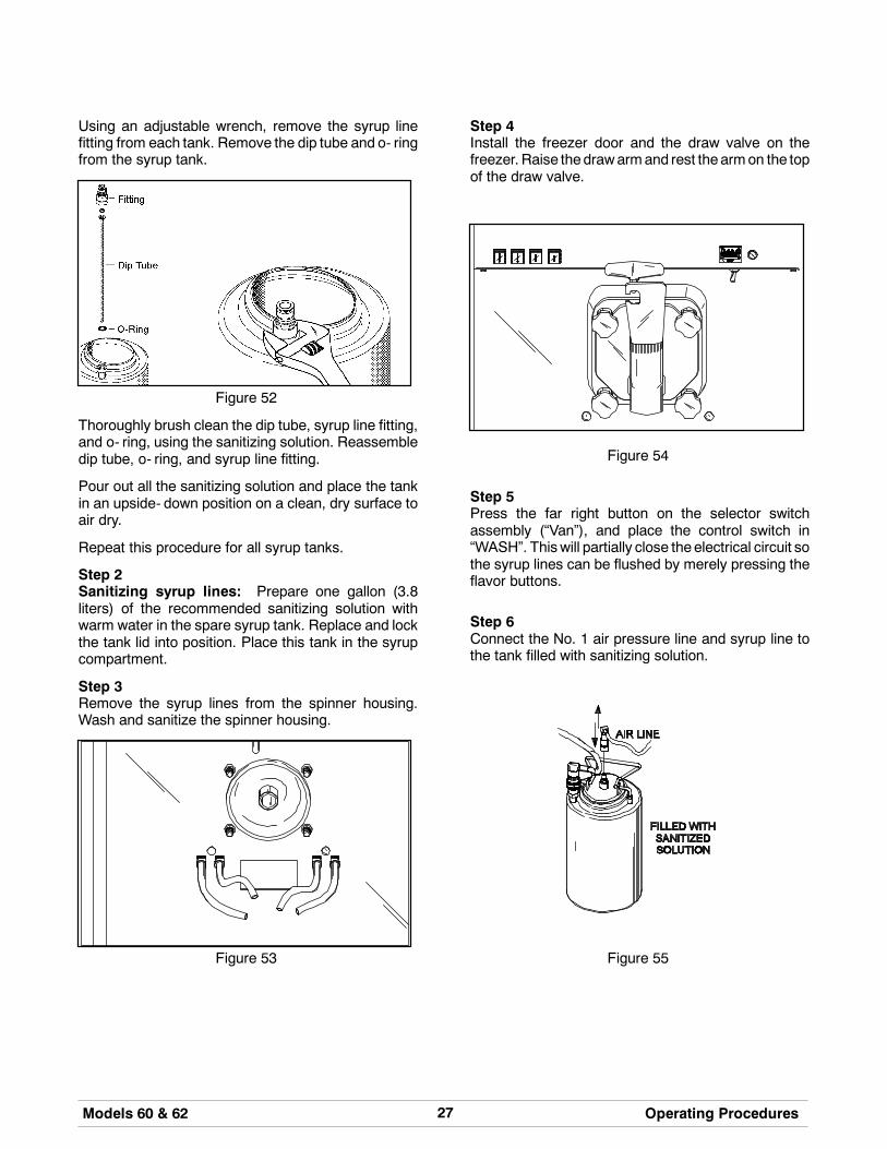
Using an adjustable wrench, remove the syrup linefitting from each tank. Remove the dip tube and o- ringfrom the syrup tank.
Figure 52
Thoroughly brush clean the dip tube, syrup line fitting,and o- ring, using the sanitizing solution. Reassembledip tube, o- ring, and syrup line fitting.
Pour out all the sanitizing solution and place the tankin an upside- down position on a clean, dry surface toair dry.
Repeat this procedure for all syrup tanks.
Step 2Sanitizing syrup lines: Prepare one gallon (3.8liters) of the recommended sanitizing solution withwarm water in the spare syrup tank. Replace and lockthe tank lid into position. Place this tank in the syrupcompartment.
Step 3Remove the syrup lines from the spinner housing.Wash and sanitize the spinner housing.
Figure 53
Step 4Install the freezer door and the draw valve on thefreezer. Raise thedrawarmand rest the armon the topof the draw valve.
Figure 54
Step 5Press the far right button on the selector switchassembly (“Van”), and place the control switch in“WASH”. Thiswill partially close theelectrical circuit sothe syrup lines can be flushed by merely pressing theflavor buttons.
Step 6Connect the No. 1 air pressure line and syrup line tothe tank filled with sanitizing solution.
Figure 55

28 Models 60 & 62Operating Procedures
Step 7Place an empty pail beneath the ends of the syruplines. Press the left flavor button and flush the No. 1syrup line until the solution runs clear. Press the farright button (“Van”) to stop the flow of sanitizingsolution.
Figure 56
Note: This procedure will thoroughly clean the endsof the syrup lines that attach to the spinner housing toprevent bacteria build- up.
Step 8Disconnect the No. 1 air and syrup lines from the tanknow partially filled with sanitizer.
Step 9Connect the No. 2 air and syrup lines to the tank andrepeat the procedure by pressing the second flavorbutton from the left, and soon, until all three syrup lineshave been cleaned and sanitized.
Step 10The fourth syrup line is for the spinner rinse. Toeffectively sanitize the end of this syrup line, use asmall amount of fresh sanitizer on a brush and brushclean theendof the fourth syrup line. Press the spinnerrinse button to further flush this rinse line.
Repeat this step for each syrup line.
Step 11Disconnect theair line and syrup line from the tankwiththe remaining sanitizer in it. Remove the tank lid andpour out all the remaining sanitizing solution. Place thetank in an upside down position on a clean, dry surfaceto air dry.
Step 12Attach the syrup lines to the spinner housing.
Step 13Remove the freezer door and the draw valve.

29Models 60 & 62 Important: Operator Checklist
120109
Section 7 Important: Operator Checklist
During Cleaning and Sanitizing:
Cleaning and sanitizing schedules are governedby federal, state, or local regulatory agencies,and must be followed accordingly. If the unithas a “Standby mode”, it must not be used inlieu of proper cleaning and sanitizingprocedures and frequencies set forth by theruling health authority. The following checkpoints should be stressed during the cleaningand sanitizing operations.
CLEANING AND SANITIZING MUST BEPERFORMED DAILY.
ALWAYS FOLLOW LOCAL HEALTH CODES.
Troubleshooting Bacterial Count:
j 1. Thoroughly clean and sanitize machineregularly, including complete disassembly andbrush cleaning.
j 2. Use all brushes supplied for thorough cleaning.The brushes are specially designed to reach allmix passageways.
j 3. Use the white bristle brush to clean the mix inlethole which extends from the mix hopper downto the rear of the freezing cylinder.
j 4. Use the black bristle brush to thoroughly cleanthe rear shell bearing located at the rear of thefreezing cylinder. Be sure to have a generousamount of cleaning solution on the brush.
j 5. IF LOCAL HEALTH CODES PERMIT THEUSE OF RERUN make sure the mix rerun isstored in a sanitized, covered stainless steelcontainer and used the following day. DO NOTprime the machine with rerun. When usingrerun, skimoff foamanddiscard; thenmix it withfresh mix in a ratio of 50/50 during the day’soperation.
j 6. On a designated day of theweek, run themix aslow as feasible and discard after closing. Thiswill break the rerun cycle and reduce thepossibility of high bacteria and coliform counts.
j 7. Properly prepare the cleaning and sanitizingsolutions. Read and follow label directionscarefully. Too STRONG of a solution maydamage the parts and too WEAK of a solutionwill not do an adequate job of cleaning orsanitizing.
j 8. Empty all syrup from the tanks and discard atleast once a week.
j 9. Thoroughly clean and sanitize the syrup lines atleast once a week.
j10. Temperature of mix in mix hopper and walk- incooler should be below 40_F. (4.4_C.).
Regular Maintenance Checks:
j 1. Rotate scraper blades to allow both sides of theknife edge to wear evenly. This will contribute toself- sharpeningandhelpmaintain fast, efficientfreezing.
j 2. Replace scraper blades that are nicked,damaged or worn.
j 3. Before installing beater, be certain that scraperblades are properly attached over the beaterpins
j 4. Check rear shell bearing for signs of wear(excessive mix leakage in rear drip pan) and becertain it is properly cleaned.
j 5. Using a screwdriver and cloth towel, keep thefemale hex drive socket clean and free oflubricant and mix deposits.

30 Models 60 & 62Important: Operator Checklist
080626
j 6. Dispose of o- rings and seals if they are worn,torn, or fit too loosely, and replace with newones.
j 7. Follow all lubricating procedures as outlined in“Assembly”.
j 8. If your machine is air cooled, check thecondenser for accumulation of dirt and lint.Dirtycondensers will reduce the efficiency andcapacity of themachine. Condensers should becleaned monthly with a soft brush. Never usescrewdrivers or other metal probes to cleanbetween the fins.Note: For machines equipped with an air filter,it will be necessary to vacuum clean the filterson a monthly schedule.
j 9. On water cooled units, check the water lines forkinks or leaks. Kinks can occur when themachine is moved back and forth for cleaningormaintenance purposes. Deteriorated orcracked water lines should be replaced only byan authorized Taylor mechanic.
Winter Storage
If the placeof business is to be closedduring thewintermonths, it is important to protect the freezer byfollowing certain precautions, particularly if thebuilding is to be left unheated and subject to freezingconditions.
Disconnect the freezer from the main power source toprevent possible electrical damage.
On water cooled freezers, disconnect the watersupply. Relieve pressure on spring in water valve. Useair pressure on the outlet side to blow out any waterremaining in the condenser. This is extremelyimportant. Failure to follow this procedure may causesevere and costly damage to the refrigeration system.
Your local Taylor Distributor can perform this servicefor you.
Wrap detachable parts of the freezer such as beater,blades, drive shaft, and freezer door, and place in aprotected dry place. Rubber trim parts and gasketscan be protected by wrapping with moisture- proofpaper. All parts should be thoroughly cleaned of driedmix or lubrication accumulations which attract miceand other vermin.

31Models 60 & 62 Troubleshooting Guide
070131
Section 8 Troubleshooting Guide
PROBLEM PROBABLE CAUSE REMEDY PAGEREF.
1. No product beingdispensed.
a. Inadequate mix in mixhopper.
a. Fill mix hopper. 20
b. Control switch is in the“OFF” position.
b. Place control switch in the“AUTO” position.
20
c. Freeze- up in mix inlettube.
c. Call service technician toadjust mix hoppertemperature.
- - -
d. Beater motor out on reset. d. Reset freezer. 12
e. Wrong beater rotation. e. Call service technician tocorrect rotation. Shouldrotate clockwise from theoperator’s end.
- - -
f. Beater motor will notactivate with draw arm inthe raised position.
f. An electrical problemrequiring a service call.
- - -
g. Frozen clumps of productblocking flow of mix tofreezing cylinder.
g. Improper handling ofrerun. Rerun must bethawed completely andfoam must be skimmedoff. Always mix 50% freshmix with 50% rerun.
29
h. Draw arm not engaged indraw valve.
h. Center draw valve ondraw arm.
17
2. Product too stiff. a. Improper lubrication oftorque rotor o- rings.
a. Lubricate o- rings properly. 14
b. Improper consistencycontrol adjustment.
b. Product, with no syrupblended, should bedispensed at 26 to 28_F(- 3.3 to - 2.2_C).
12
c. Torque rotor binding. c. Before installing thetorque arm, check to seeif torque rotor can berotated freely withoutbinding.
14
d. Not enough syrup beingblended with product.
d. Calibrate the syrupsystem. Syrup deliveryshould be 1 oz. (29.6 ml.)in 6 seconds.
22
e. Torque arm not installed. e. Install torque arm. 17

32 Models 60 & 62Troubleshooting Guide
070131
PROBLEM PROBABLE CAUSE REMEDY PAGEREF.
3. Product too soft. a. Improper consistencycontrol adjustment.
a. Product, with no syrupblended, should bedispensed at 26 to 28_F(- 3.3 to - 2.2_C).
12
b. Torque rotor binding. b. Before installing thetorque arm, check to seeif the torque rotor can berotated freely withoutbinding.
14
c. Improper lubrication oftorque rotor o- rings.
c. Lubricate o- rings properly. 14
d. Lubrication of torque rotorguide bearing.
d. Do not lubricate guidebearing.
14
e. Too much syrup beingblended with product.
e. Calibrate the syrupsystem. Syrup deliveryshould be 1 oz. (29.6 ml.)in 6 seconds.
22
f. Bad scraper blades. f. Replace scraper blades. 35
g. Dirty condenser. g. Brush condenser cleanevery 30 days.
30
4. Large pressureadjustments arenecessary to receive 1 oz.(29.6 ml.) in 6 seconds.
a. Hardened syrup in syrupline.
a. Sanitize syrup lines oncea week.
26
b. Syrup line and air line notmatched properly to syruptank.
b. Match syrup and air linesto syrup tank.
21
5. Mix hopper too warm. a. Product too warm whenplaced in hopper.
a. Check temperature instorage cooler.
29
b. Control switch in the“OFF” position.
b. Place in “AUTO” position. 20
c. Needs temperatureadjustment.
c. Call service technician tomake adjustment.
- - -
6. Mix hopper too cold. a. Needs temperatureadjustment.
a. Call service technician tomake adjustment.
- - -
7. Machine short cycling(rapid on and off cycles).
a. Dirty air cooledcondenser.
a. Brush clean every 30days.
30
b. Inadequate water supplyon water cooled unit.
b. Check water supply. 2
c. Defective condenser fan. c. Call service technician torepair or replace.
- - -
d. No air space surroundingmachine.
d. Maintain specified airclearance.
2

33Models 60 & 62 Troubleshooting Guide
150626
PROBLEM PROBABLE CAUSE REMEDY PAGEREF.
8. The freezing cylinder wallsare scored.
a. The scraper blades and/orblade clips are damaged.
a. Replace the scraperblades and/or clips.
14
b. Unit was placed in AUTObefore all sanitizingsolution was removedfrom freezing cylinder.
b. Place unit in AUTO onlyafter priming is completeand all sanitizing solutionis removed.
19
c. The front bearing ismissing or worn on thefreezer door.
c. Install or replace the frontbearing.
16
d. The beater assembly isbent.
d. Call service technician torepair or replace thebeater and to correct thecause of insufficient mix inthe freezing cylinder.
- - -
e. Broken beater pins. e. Call service technician torepair or replace.
- - -
9. Drive shaft stuck in gearbox coupling.
a. Lubrication on hex end ofshaft.
a. Call service techician forremoval.
- - -
b. Rounded corners of hexend of drive shaft.
b. Replace defective driveshaft.
- - -
c. Rounded corners ofcoupling on gear box.
c. Call service technician toreplace gear box.
- - -
10. Excessive leakage of mixinto rear drip pan.
a. Worn or missing seal ondrive shaft.
a. Replace every 3 months. 35
b. Inadequate lubrication ofdrive shaft.
b. Follow lubricationprocedures in “Assembly”.
13
c. Bad rear shell bearing. c. Call service technician toreplace rear shell bearing.
- - -
d. Drive shaft and beaterworking forward.
d. Call service technician. - - -
11. Machine will not operatewhen control switch is in“AUTO”.
a. Draw arm not raised. a. Raise draw armmomentarily to activatesystem.
20
b. Beater motor out on reset. b. Reset freezer. 12
c. Circuit breaker off. c. Turn breaker on. - - -
d. Water turned off (watercooled units).
d. Re- establish watersupply.
- - -
e. Power cord unplugged. e. Plug cord into wallreceptacle.
- - -

34 Models 60 & 62Troubleshooting Guide
PROBLEM PROBABLE CAUSE REMEDY PAGEREF.
12. Water continues to flowthrough spinner housing.
a. Rinse solenoid stuckopen.
a. Call service technician forrepair.
- - -
13. Lift motor continues toraise draw valve afterdraw of product has beenmade.
a. Micro switch needsadjustment.
a. Call service technician forrepair.
- - -
14. Air compressor runs toooften for normal usage.
a. Air leak in system. a. Use a soap solution tolocate the leak.
- - -
15. Spinner shaft will notrotate to blend syrup intoproduct.
a. Flexible cable broken. a. Call service technician toreplace cable.
- - -
b. Pin missing in femalequick disconnect.
b. Call service technician toreplace disconnect.
- - -
c. Spinner motor out onthermal overload.
c. Inadequate lubrication ofspinner shaft. Lubricateentire length of shaft.
16
16. Excessive drippage ofproduct from spinnerhousing.
a. Worn o- rings on drawvalve.
a. Replace every 3 months. 35
b. Wrong o- rings on drawvalve.
b. Check o- ring size. - - -
c. Inadequate lubrication ofspinner shaft.
c. Follow lubricationprocedures in “Assembly”.
16

35Models 60 & 62 Parts Replacement Schedule
Section 9 Parts Replacement Schedule
PART DESCRIPTION EVERY 3 MONTHS EVERY 6 MONTHS ANNUALLY QUANTITIES TOBE REPLACED
Drive Shaft Seal X 1
Scraper Blades Inspect & Replaceif Necessary
Minimum 2
Freezer Door Gasket X 1
Front Bearing X 1
Draw Valve O- Rings X 2
Torque Rotor Guide Bearing X 1
Torque Rotor O- Rings X 2
Feed Assembly O- Rings X 2
Double Ended Brush Inspect & Replaceif Necessary
Minimum 1
Black Bristle Brush, 1” x 2” Inspect & Replaceif Necessary
Minimum 1
White Bristle Brush, 1- 1/2” x 2” Inspect & Replaceif Necessary
Minimum 1
White Bristle Brush, 3” x 7” Inspect & Replaceif Necessary
Minimum 1
Tune- UpKits are available fromyour TaylorDistributor. Keep your freezer in top condition with the above replacementparts in a “Tune- Up Kit” for your model of freezer! Ask your Taylor Distributor about the Automatic 3- Month Tune- UpKit Mailing Program.

36 Models 60 & 62Limited Warranty on Equipment
131108
Section 10 Limited Warranty on EquipmentTAYLOR COMPANY LIMITED WARRANTY ON FREEZERS
Taylor Company, a division of Carrier Commercial Refrigeration, Inc. (“Taylor”) is pleased to provide this limitedwarranty on new Taylor-branded freezer equipment available from Taylor to the market generally (the “Product”)to the original purchaser only.
LIMITED WARRANTY
Taylor warrants the Product against failure due to defect in materials or workmanship under normal use andservice as follows. All warranty periods begin on the date of original Product installation. If a part fails due todefect during the applicable warranty period, Taylor, through an authorized Taylor distributor or service agency,will provide a new or re- manufactured part, at Taylor’s option, to replace the failed defective part at no charge forthe part. Except as otherwise stated herein, these are Taylor’s exclusive obligations under this limited warranty fora Product failure. This limited warranty is subject to all provisions, conditions, limitations and exclusions listedbelow and on the reverse (if any) of this document.
Product Part Limited Warranty Period
Soft ServeFrozen YogurtShakesSmoothies
Frozen BeverageBatch Desserts
Insulated shell assembly Five (5) years
Refrigeration compressor(except service valve)
Five (5) years
Beater motors Two (2) years
Beater drive gear Two (2) years
Printed circuit boards andSoftech controls beginningwith serial number H8024200
Two (2) years
Parts not otherwise listed inthis table or excluded below
One (1) year
LIMITED WARRANTY CONDITIONS
1. If the date of original installation of the Product cannot be verified, then the limited warranty period beginsninety (90) days from the date of Product manufacture (as indicated by the Product serial number). Proof ofpurchase may be required at time of service.
2. This limited warranty is valid only if the Product is installed and all required service work on the Product isperformed by an authorized Taylor distributor or service agency, and only if genuine, new Taylor parts areused.
3. Installation, use, care, and maintenance must be normal and in accordance with all instructions contained inthe Taylor Operator’s Manual.
4. Defective parts must be returned to the authorized Taylor distributor or service agency for credit.
5. The use of any refrigerant other than that specified on the Product’s data label will void this limited warranty.
LIMITED WARRANTY EXCEPTIONS
This limited warranty does not cover:
1. Labor or other costs incurred for diagnosing, repairing, removing, installing, shipping, servicing or handling ofdefective parts, replacement parts, or new Products.
2. Normal maintenance, cleaning and lubrication as outlined in the Taylor Operator’s Manual, including cleaningof condensers.

37Models 60 & 62 Limited Warranty on Equipment131108
3. Replacement of wear items designated as Class “000” parts in the Taylor Operator’s Manual.
4. External hoses, electrical power supplies, and machine grounding.
5. Parts not supplied or designated by Taylor, or damages resulting from their use.
6. Return trips or waiting time required because a service technician is prevented from beginning warrantyservice work promptly upon arrival.
7. Failure, damage or repairs due to faulty installation, misapplication, abuse, no or improper servicing,unauthorized alteration or improper operation or use as indicated in the Taylor Operator’s Manual, includingbut not limited to the failure to use proper assembly and cleaning techniques, tools, or approved cleaningsupplies.
8. Failure, damage or repairs due to theft, vandalism, wind, rain, flood, high water, water, lightning, earthquakeor any other natural disaster, fire, corrosive environments, insect or rodent infestation, or other casualty,accident or condition beyond the reasonable control of Taylor; operation above or below the electrical orwater supply specification of the Product; or components repaired or altered in any way so as, in thejudgment of the Manufacturer, to adversely affect performance, or normal wear or deterioration.
9. Any Product purchased over the Internet.
10. Failure to start due to voltage conditions, blown fuses, open circuit breakers, or damages due to theinadequacy or interruption of electrical service.
11. Electricity or fuel costs, or increases in electricity or fuel costs from any reason whatsoever.
12. Damages resulting from the use of any refrigerant other than that specified on the Product’s data label willvoid this limited warranty.
13. Any cost to replace, refill or dispose of refrigerant, including the cost of refrigerant.
14. ANY SPECIAL, INDIRECT OR CONSEQUENTIAL PROPERTY OR COMMERCIAL DAMAGE OF ANYNATURE WHATSOEVER. Some jurisdictions do not allow the exclusion of incidental or consequentialdamages, so this limitation may not apply to you.
This limited warranty gives you specific legal rights, and you may also have other rights which vary fromjurisdiction to jurisdiction.
LIMITATION OF WARRANTY
THIS LIMITED WARRANTY IS EXCLUSIVE AND IS IN LIEU OF ALL OTHER WARRANTIES, CONDITIONSAND/OR REMEDIES UNDER THE LAW, INCLUDING ANY IMPLIED WARRANTIES OR CONDITIONS OFMERCHANTABILITY OR FITNESS FOR A PARTICULAR PURPOSE. THE ORIGINAL OWNER’S SOLEREMEDY WITH RESPECT TO ANY PRODUCTS SHALL BE REPAIR OR REPLACEMENT OF DEFECTIVECOMPONENTS UNDER THE TERMS OF THIS LIMITED WARRANTY. ALL RIGHTS TO CONSEQUENTIALOR INCIDENTAL DAMAGES (INCLUDING CLAIMS FOR LOST SALES, LOST PROFITS, PRODUCT LOSS,PROPERTY DAMAGES OR SERVICE EXPENSES) ARE EXPRESSLY EXCLUDED. THE EXPRESSWARRANTIES MADE IN THIS LIMITED WARRANTY MAY NOT BE ALTERED, ENLARGED, OR CHANGEDBY ANY DISTRIBUTOR, DEALER, OR OTHER PERSON, WHATSOEVER.
LEGAL REMEDIES
The owner must notify Taylor in writing, by certified or registered letter to the following address, of any defect orcomplaint with the Product, stating the defect or complaint and a specific request for repair, replacement, or othercorrection of the Product under warranty, mailed at least thirty (30) days before pursuing any legal rights orremedies.
Taylor Companya division of Carrier Commercial Refrigeration, Inc.
750 N. Blackhawk Blvd.Rockton, IL 61072, U.S.A.

38 Models 60 & 62Limited Warranty on Parts
131108
Section 11 Limited Warranty on PartsTAYLOR COMPANY LIMITED WARRANTY ON TAYLOR GENUINE PARTS
Taylor Company, a division of Carrier Commercial Refrigeration, Inc. (“Taylor”) is pleased to provide this limitedwarranty on new Taylor genuine replacement components and parts available from Taylor to the market generally(the “Parts”) to the original purchaser only.
LIMITED WARRANTY
Taylor warrants the Parts against failure due to defect in materials or workmanship under normal use and serviceas follows. All warranty periods begin on the date of original installation of the Part in the Taylor unit. If a Part failsdue to defect during the applicable warranty period, Taylor, through an authorized Taylor distributor or serviceagency, will provide a new or re- manufactured Part, at Taylor’s option, to replace the failed defective Part at nocharge for the Part. Except as otherwise stated herein, these are Taylor’s exclusive obligations under this limitedwarranty for a Part failure. This limited warranty is subject to all provisions, conditions, limitations and exclusionslisted below and on the reverse (if any) of this document.
Part’s Warranty Class Code or Part Limited Warranty Period
Class 103 Parts¹ Three (3) months
Class 212 Parts² Twelve (12) months
Class 512 Parts Twelve (12) months
Class 000 Parts No warranty
Taylor Part #072454 (Motor- 24VDC *C832/C842*) Four (4) years
LIMITED WARRANTY CONDITIONS
1. If the date of original installation of the Part cannot be otherwise verified, proof of purchase may be requiredat time of service.
2. This limited warranty is valid only if the Part is installed and all required service work in connection with thePart is performed by an authorized Taylor distributor or service agency.
3. The limited warranty applies only to Parts remaining in use by their original owner at their original installationlocation in the unit of original installation.
4. Installation, use, care, and maintenance must be normal and in accordance with all instructions contained inthe Taylor Operator’s Manual.
5. Defective Parts must be returned to the authorized Taylor distributor or service agency for credit.
6. This warranty is not intended to shorten the length of any warranty coverage provided pursuant to a separateTaylor Limited Warranty on freezer or grill equipment.
7. The use of any refrigerant other than that specified for the unit in which the Part is installed will void thislimited warranty.
1, 2 Except that Taylor Part #032129SER2 (Compressor-Air-230V SERV) and Taylor Part #075506SER1(Compressor-Air-115V 60HZ) shall have a limited warranty period of twelve (12) months when used in Taylorfreezer equipment and a limited warranty period of two (2) years when used in Taylor grill equipment.

39Models 60 & 62 Limited Warranty on Parts131108
LIMITED WARRANTY EXCEPTIONS
This limited warranty does not cover:
1. Labor or other costs incurred for diagnosing, repairing, removing, installing, shipping, servicing or handling ofdefective Parts, replacement Parts, or new Parts.
2. Normal maintenance, cleaning and lubrication as outlined in the Taylor Operator’s Manual, including cleaningof condensers or carbon and grease buildup.
3. Required service, whether cleaning or general repairs, to return the cooking surface assemblies, includingthe upper platen and lower plate, to an operational condition to achieve proper cooking or allow properassembly of release sheets and clips as a result of grease build-up on the cooking surfaces, including butnot limited to the platen and plate, sides of the shroud or top of the shroud.
4. Replacement of cooking surfaces, including the upper platen and lower plate, due to pitting or corrosion (orin the case of the upper platen, due to loss of plating) as a result of damage due to the impact of spatulas orother small wares used during the cooking process or as a result of the use of cleaners, cleaning materialsor cleaning processes not approved for use by Taylor.
5. Replacement of wear items designated as Class “000” Parts in the Taylor Operator’s Manual, as well as anyrelease sheets and clips for the Product’s upper platen assembly.
6. External hoses, electrical power supplies, and machine grounding.
7. Parts not supplied or designated by Taylor, or damages resulting from their use.
8. Return trips or waiting time required because a service technician is prevented from beginning warrantyservice work promptly upon arrival.
9. Failure, damage or repairs due to faulty installation, misapplication, abuse, no or improper servicing,unauthorized alteration or improper operation or use as indicated in the Taylor Operator’s Manual, includingbut not limited to the failure to use proper assembly and cleaning techniques, tools, or approved cleaningsupplies.
10. Failure, damage or repairs due to theft, vandalism, wind, rain, flood, high water, water, lightning, earthquakeor any other natural disaster, fire, corrosive environments, insect or rodent infestation, or other casualty,accident or condition beyond the reasonable control of Taylor; operation above or below the gas, electrical orwater supply specification of the unit in which a part is installed; or Parts or the units in which they areinstalled repaired or altered in any way so as, in the judgment of Taylor, to adversely affect performance, ornormal wear or deterioration.
11. Any Part purchased over the Internet.
12. Failure to start due to voltage conditions, blown fuses, open circuit breakers, or damages due to theinadequacy or interruption of electrical service.
13. Electricity, gas or other fuel costs, or increases in electricity or fuel costs from any reason whatsoever.
14. Damages resulting from the use of any refrigerant other than that specified for the unit in which the Part isinstalled will void this limited warranty.
15. Any cost to replace, refill or dispose of refrigerant, including the cost of refrigerant.
16. ANY SPECIAL, INDIRECT OR CONSEQUENTIAL PROPERTY OR COMMERCIAL DAMAGE OF ANYNATURE WHATSOEVER. Some jurisdictions do not allow the exclusion of incidental or consequentialdamages, so this limitation may not apply to you.
This limited warranty gives you specific legal rights, and you may also have other rights which vary fromjurisdiction to jurisdiction.

40 Models 60 & 62Limited Warranty on Parts
131108
LIMITATION OF WARRANTY
THIS LIMITED WARRANTY IS EXCLUSIVE AND IS IN LIEU OF ALL OTHER WARRANTIES, CONDITIONSAND/OR REMEDIES UNDER THE LAW, INCLUDING ANY IMPLIED WARRANTIES OR CONDITIONS OFMERCHANTABILITY OR FITNESS FOR A PARTICULAR PURPOSE. THE ORIGINAL OWNER’S SOLEREMEDY WITH RESPECT TO ANY PRODUCTS SHALL BE REPAIR OR REPLACEMENT OF DEFECTIVEPARTS UNDER THE TERMS OF THIS LIMITED WARRANTY. ALL RIGHTS TO CONSEQUENTIAL ORINCIDENTAL DAMAGES (INCLUDING CLAIMS FOR LOST SALES, LOST PROFITS, PRODUCT LOSS,PROPERTY DAMAGES OR SERVICE EXPENSES) ARE EXPRESSLY EXCLUDED. THE EXPRESSWARRANTIES MADE IN THIS LIMITED WARRANTY MAY NOT BE ALTERED, ENLARGED, OR CHANGEDBY ANY DISTRIBUTOR, DEALER, OR OTHER PERSON, WHATSOEVER.
LEGAL REMEDIES
The owner must notify Taylor in writing, by certified or registered letter to the following address, of any defect orcomplaint with the Part, stating the defect or complaint and a specific request for repair, replacement, or othercorrection of the Part under warranty, mailed at least thirty (30) days before pursuing any legal rights or remedies.
Taylor Companya division of Carrier Commercial Refrigeration, Inc.
750 N. Blackhawk Blvd.Rockton, IL 61072, U.S.A.


