The information contained within this document must not be copied, reprinted or reproduced in any form, either wholly or in part, without the written consent of M-TEC, The information is believed to be correct at the time of issue to the best of M-TEC’s knowledge. M-TEC reserves the right to
amend this specification without prior notification. This specification is not contractually valid unless specifically authorised by M-TEC. M-TEC shall not be liable for any damages whatsoever (including indirect, incidental, special, punitive or consequential damages and loss of profits, opportunities
or information) arising from or result from the use of or reliance on information contained in this document, and/or any inaccuracy or omission in such information contained in this document.
12 fiber: groups: 1st group (Blue), 2
nd group (Yellow)
1st tube 12 fiber: groups: 1
st group (Blue), 2
nd group (Yellow), 3
rdgroup (Green), 4
th group (Red),
Construction
Aluminium Clad Steel
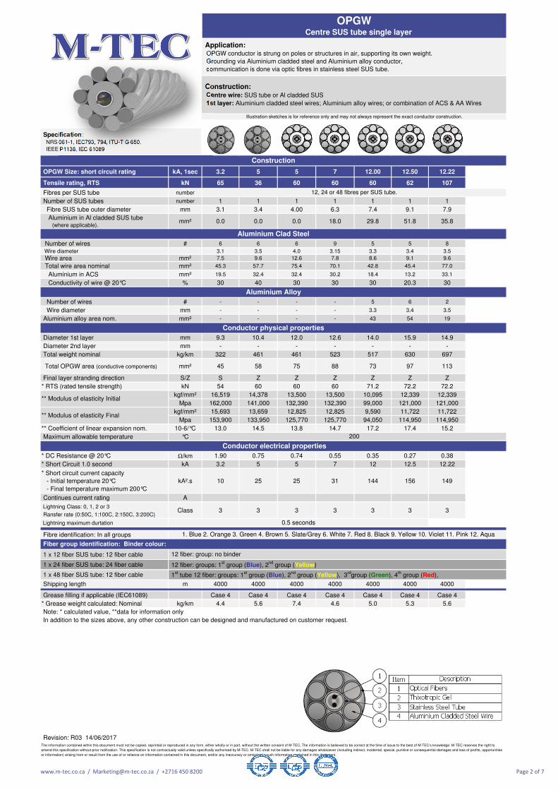
12, 24 or 48 fibres per SUS tube.
Aluminium Alloy
Conductor physical properties
Conductor electrical properties
** Modulus of elasticity Final
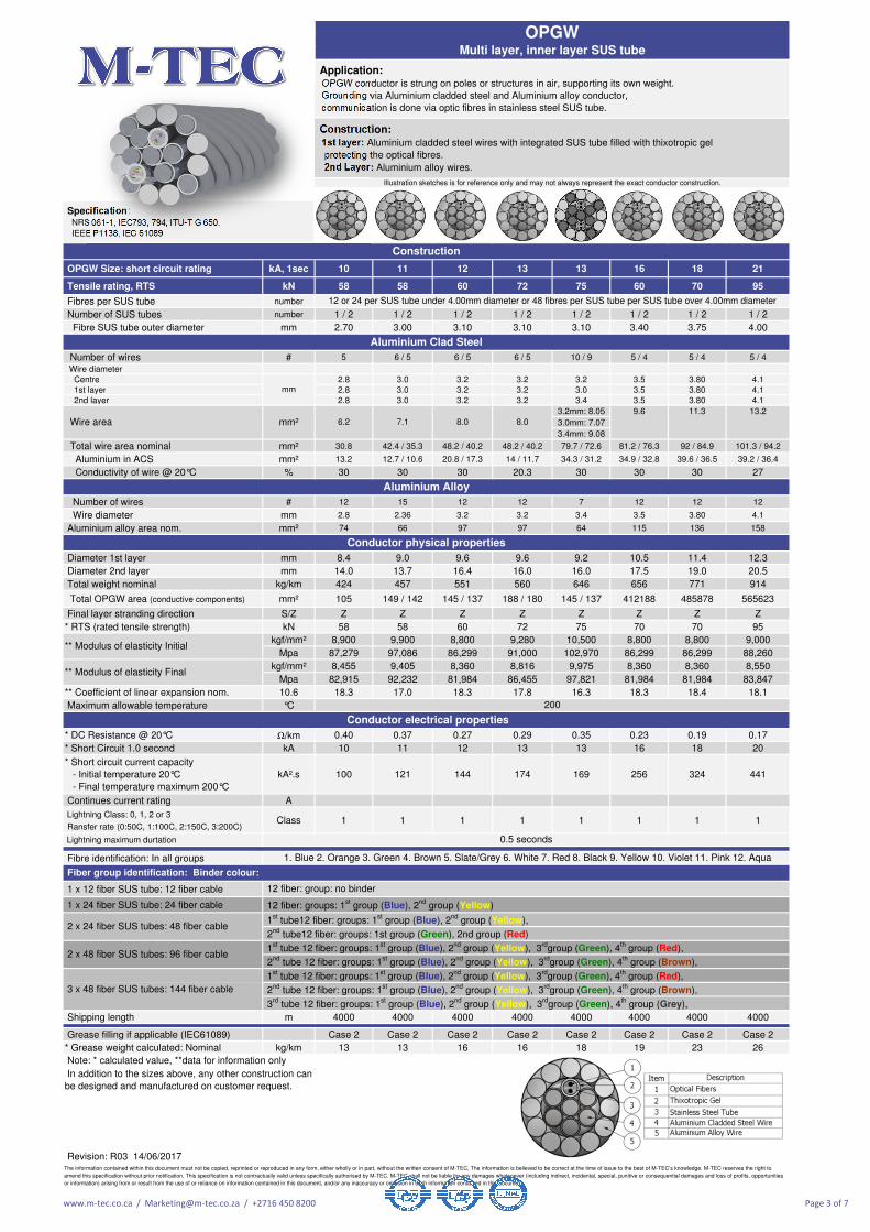
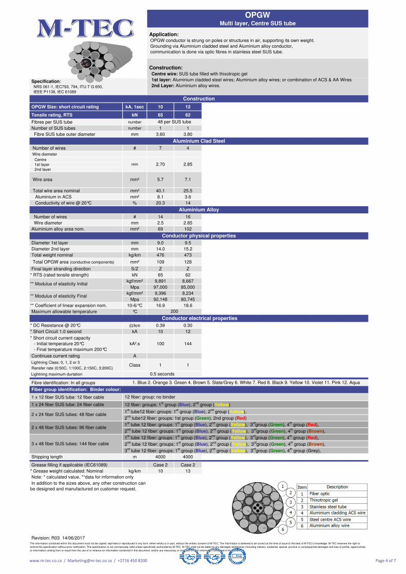
1. Blue 2. Orange 3. Green 4. Brown 5. Slate/Grey 6. White 7. Red 8. Black 9. Yellow 10. Violet 11. Pink 12. Aqua
12 fiber: group: no binder
Fiber group identification: Binder colour:
200
In addition to the sizes above, any other construction can be designed and manufactured on customer request.
Note: * calculated value, **data for information only
OPGW Centre SUS tube single layer
** Modulus of elasticity Initial
Construction: Centre wire: SUS tube or Al cladded SUS
1st layer: Aluminium cladded steel wires; Aluminium alloy wires; or combination of ACS & AA Wires
Application: OPGW conductor is strung on poles or structures in air, supporting its own weight.
Grounding via Aluminium cladded steel and Aluminium alloy conductor,
communication is done via optic fibres in stainless steel SUS tube.
Illustration sketches is for reference only and may not always represent the exact conductor construction.
Specification: NRS 061-1, IEC793, 794, ITU-T G 650,
12 or 24 per SUS tube under 4.00mm diameter or 48 fibres per SUS tube per SUS tube over 4.00mm diameter
Aluminium Clad Steel
Construction
The information contained within this document must not be copied, reprinted or reproduced in any form, either wholly or in part, without the written consent of M-TEC, The information is believed to be correct at the time of issue to the best of M-TEC’s knowledge. M-TEC reserves the right to
amend this specification without prior notification. This specification is not contractually valid unless specifically authorised by M-TEC. M-TEC shall not be liable for any damages whatsoever (including indirect, incidental, special, punitive or consequential damages and loss of profits, opportunities
or information) arising from or result from the use of or reliance on information contained in this document, and/or any inaccuracy or omission in such information contained in this document.
In addition to the sizes above, any other construction can
be designed and manufactured on customer request.
Note: * calculated value, **data for information only
3rd
tube 12 fiber: groups: 1st group (Blue), 2
nd group (Yellow), 3
rdgroup (Green), 4
th group (Grey),
2nd
tube 12 fiber: groups: 1st group (Blue), 2
nd group (Yellow), 3
rdgroup (Green), 4
th group (Brown),
1st tube 12 fiber: groups: 1
st group (Blue), 2
nd group (Yellow), 3
rdgroup (Green), 4
th group (Red),
2nd
tube 12 fiber: groups: 1st group (Blue), 2
nd group (Yellow), 3
rdgroup (Green), 4
th group (Brown),
2 x 24 fiber SUS tubes: 48 fiber cable
2 x 48 fiber SUS tubes: 96 fiber cable 1
st tube 12 fiber: groups: 1
st group (Blue), 2
nd group (Yellow), 3
rdgroup (Green), 4
th group (Red),
2nd
tube12 fiber: groups: 1st group (Green), 2nd group (Red)
1st tube12 fiber: groups: 1
st group (Blue), 2
nd group (Yellow),
3 x 48 fiber SUS tubes: 144 fiber cable
12 fiber: groups: 1st group (Blue), 2
nd group (Yellow)
12 fiber: group: no binder
Aluminium Alloy
Conductor physical properties
Conductor electrical properties
1. Blue 2. Orange 3. Green 4. Brown 5. Slate/Grey 6. White 7. Red 8. Black 9. Yellow 10. Violet 11. Pink 12. Aqua
200
Fiber group identification: Binder colour:
** Modulus of elasticity Initial
6.2 7.1 8.0
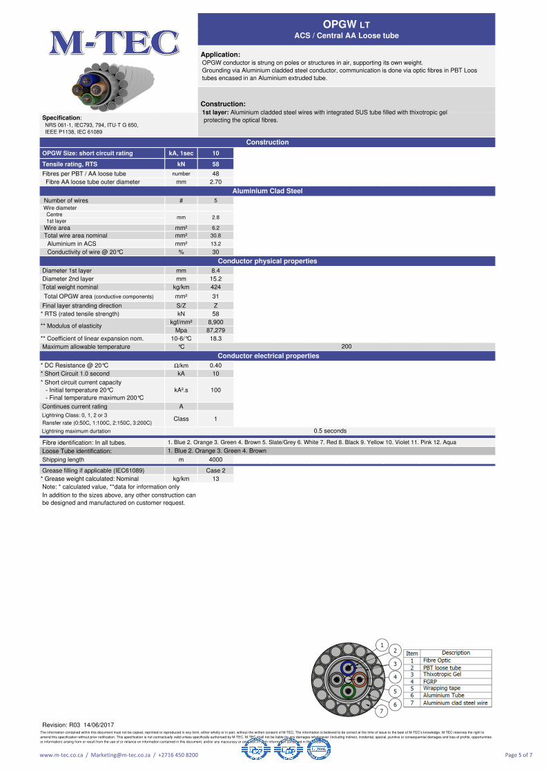
Construction: 1st layer: Aluminium cladded steel wires with integrated SUS tube filled with thixotropic gel
protecting the optical fibres.
2nd Layer: Aluminium alloy wires.
Wire area mm²
Illustration sketches is for reference only and may not always represent the exact conductor construction.
mm
Specification: NRS 061-1, IEC793, 794, ITU-T G 650,
IEEE P1138, IEC 61089
OPGW Multi layer, inner layer SUS tube
Application: OPGW conductor is strung on poles or structures in air, supporting its own weight.
Grounding via Aluminium cladded steel and Aluminium alloy conductor,
communication is done via optic fibres in stainless steel SUS tube.
Grease filling if applicable (IEC61089) Case 2 Case 2
* Grease weight calculated: Nominal kg/km 10 13
Revision: R03 14/06/2017
In addition to the sizes above, any other construction can
be designed and manufactured on customer request.
The information contained within this document must not be copied, reprinted or reproduced in any form, either wholly or in part, without the written consent of M-TEC, The information is believed to be correct at the time of issue to the best of M-TEC’s knowledge. M-TEC reserves the right to
amend this specification without prior notification. This specification is not contractually valid unless specifically authorised by M-TEC. M-TEC shall not be liable for any damages whatsoever (including indirect, incidental, special, punitive or consequential damages and loss of profits, opportunities
or information) arising from or result from the use of or reliance on information contained in this document, and/or any inaccuracy or omission in such information contained in this document.
48 per SUS tube
200
0.5 seconds
2.85
3 x 48 fiber SUS tubes: 144 fiber cable
1st tube 12 fiber: groups: 1
st group (Blue), 2
nd group (Yellow), 3
rdgroup (Green), 4
th group (Red),
2nd
tube 12 fiber: groups: 1st group (Blue), 2
nd group (Yellow), 3
rdgroup (Green), 4
th group (Brown),
3rd
tube 12 fiber: groups: 1st group (Blue), 2
nd group (Yellow), 3
rdgroup (Green), 4
th group (Grey),
Note: * calculated value, **data for information only
2 x 24 fiber SUS tubes: 48 fiber cable 1
st tube12 fiber: groups: 1
st group (Blue), 2
nd group (Yellow),
2nd
tube12 fiber: groups: 1st group (Green), 2nd group (Red)
2 x 48 fiber SUS tubes: 96 fiber cable 1
st tube 12 fiber: groups: 1
st group (Blue), 2
nd group (Yellow), 3
rdgroup (Green), 4
th group (Red),
2nd
tube 12 fiber: groups: 1st group (Blue), 2
nd group (Yellow), 3
rdgroup (Green), 4
th group (Brown),
1. Blue 2. Orange 3. Green 4. Brown 5. Slate/Grey 6. White 7. Red 8. Black 9. Yellow 10. Violet 11. Pink 12. Aqua
Fiber group identification: Binder colour:
12 fiber: group: no binder
12 fiber: groups: 1st group (Blue), 2
nd group (Yellow)
Aluminium Alloy
Conductor physical properties
** Modulus of elasticity Initial
** Modulus of elasticity Final
Conductor electrical properties
Construction: Centre wire: SUS tube filled with thixotropic gel
1st layer: Aluminium cladded steel wires; Aluminium alloy wires; or combination of ACS & AA Wires
2nd Layer: Aluminium alloy wires.
Wire area mm² 5.7 7.1
Specification: NRS 061-1, IEC793, 794, ITU-T G 650,
IEEE P1138, IEC 61089
Construction
Aluminium Clad Steel
OPGW Multi layer, Centre SUS tube
mm 2.70
Application: OPGW conductor is strung on poles or structures in air, supporting its own weight.
Grounding via Aluminium cladded steel and Aluminium alloy conductor,
communication is done via optic fibres in stainless steel SUS tube.
Construction: 1st layer: Aluminium cladded steel wires with integrated SUS tube filled with thixotropic gel
protecting the optical fibres.
Application: OPGW conductor is strung on poles or structures in air, supporting its own weight.
Grounding via Aluminium cladded steel conductor, communication is done via optic fibres in PBT Loos
tubes encased in an Aluminium extruded tube.
Specification: NRS 061-1, IEC793, 794, ITU-T G 650,
IEEE P1138, IEC 61089
Construction
Aluminium Clad Steel
Note: * calculated value, **data for information only
In addition to the sizes above, any other construction can
be designed and manufactured on customer request.
The information contained within this document must not be copied, reprinted or reproduced in any form, either wholly or in part, without the written consent of M-TEC, The information is believed to be correct at the time of issue to the best of M-TEC’s knowledge. M-TEC reserves the right to
amend this specification without prior notification. This specification is not contractually valid unless specifically authorised by M-TEC. M-TEC shall not be liable for any damages whatsoever (including indirect, incidental, special, punitive or consequential damages and loss of profits, opportunities
or information) arising from or result from the use of or reliance on information contained in this document, and/or any inaccuracy or omission in such information contained in this document.
mm 2.8
Conductor electrical properties
1. Blue 2. Orange 3. Green 4. Brown 5. Slate/Grey 6. White 7. Red 8. Black 9. Yellow 10. Violet 11. Pink 12. Aqua
Product reliability is ensured through rigorous qualification testing of each product family.
Both initial and periodic qualification testing are performed to assure the cable's performance and durability in the field environments.
Level of quality in our cable products is ensured through several quality control program including ISO 9001.
Loose tube conductor is a design that has high tensile strength and flexibility in a compact cable size.
The stainless steel loose tube cable provides excellent optical transmission and physical performance.
The information contained within this document must not be copied, reprinted or reproduced in any form, either wholly or in part, without the written consent of M-TEC, The information is believed to be correct at the time of issue to the best of M-TEC’s knowledge. M-TEC reserves the right to
amend this specification without prior notification. This specification is not contractually valid unless specifically authorised by M-TEC. M-TEC shall not be liable for any damages whatsoever (including indirect, incidental, special, punitive or consequential damages and loss of profits, opportunities
or information) arising from or result from the use of or reliance on information contained in this document, and/or any inaccuracy or omission in such information contained in this document.
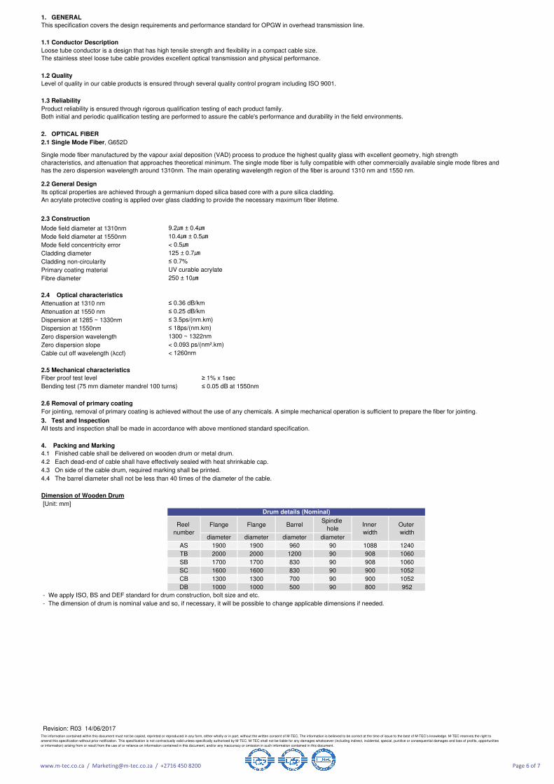
- The dimension of drum is nominal value and so, if necessary, it will be possible to change applicable dimensions if needed.
All tests and inspection shall be made in accordance with above mentioned standard specification.
< 1260nm
Reel
number
For jointing, removal of primary coating is achieved without the use of any chemicals. A simple mechanical operation is sufficient to prepare the fiber for jointing.
- We apply ISO, BS and DEF standard for drum construction, bolt size and etc.
125 ± 0.7
≤ 0.36 dB/km
≤ 0.25 dB/km
≤ 3.5ps/(nm.km)
≤ 18ps/(nm.km)
Inner
width
Outer
width
Its optical properties are achieved through a germanium doped silica based core with a pure silica cladding.
An acrylate protective coating is applied over glass cladding to provide the necessary maximum fiber lifetime.
UV curable acrylate
250 ± 10
9.2 ± 0.4
10.4 ± 0.5
≤ 0.7%
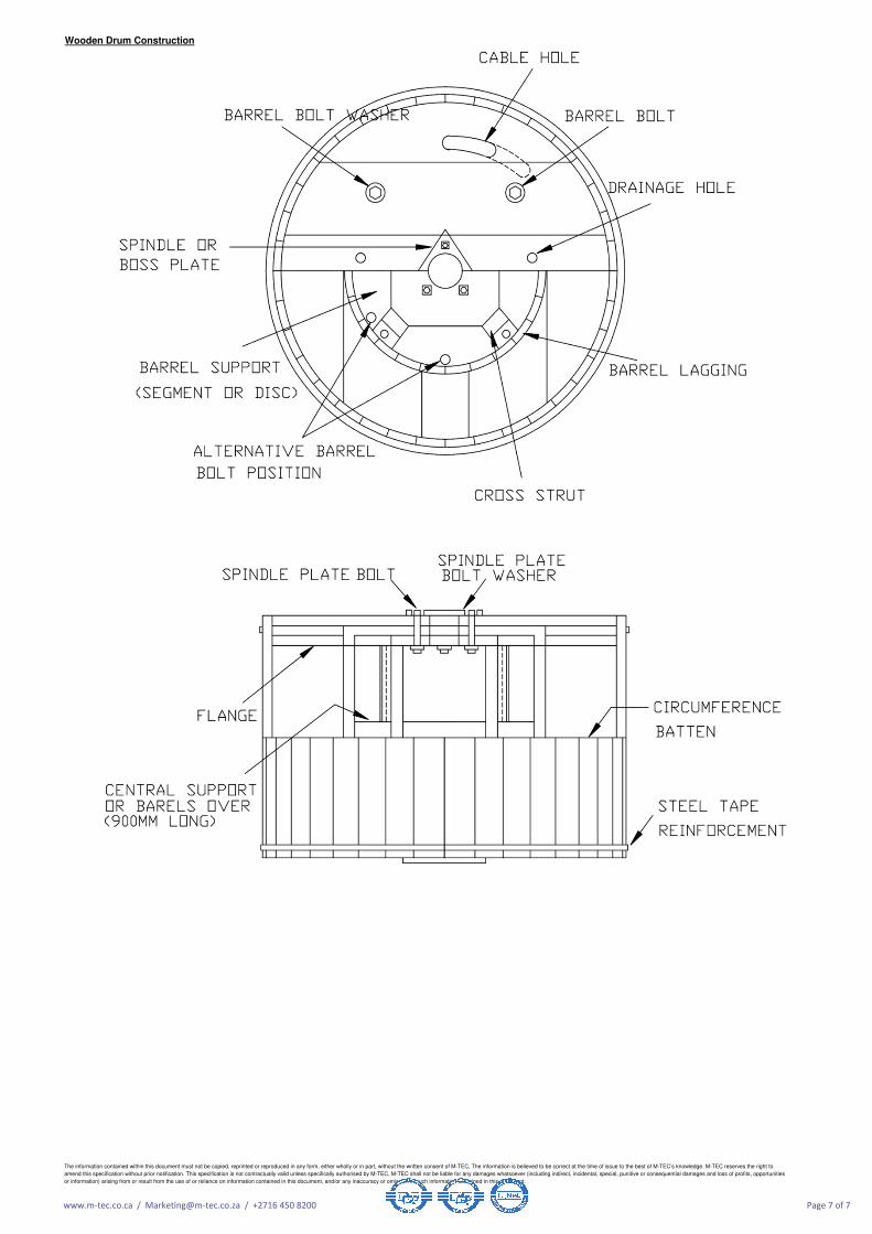
4.1 Finished cable shall be delivered on wooden drum or metal drum.
1300 ~ 1322nm
< 0.093 ps/(nm².km)
4.4 The barrel diameter shall not be less than 40 times of the diameter of the cable.
4.2 Each dead-end of cable shall have effectively sealed with heat shrinkable cap.
4.3 On side of the cable drum, required marking shall be printed.
Single mode fiber manufactured by the vapour axial deposition (VAD) process to produce the highest quality glass with excellent geometry, high strength
characteristics, and attenuation that approaches theoretical minimum. The single mode fiber is fully compatible with other commercially available single mode fibres and
has the zero dispersion wavelength around 1310nm. The main operating wavelength region of the fiber is around 1310 nm and 1550 nm.
This specification covers the design requirements and performance standard for OPGW in overhead transmission line.
The information contained within this document must not be copied, reprinted or reproduced in any form, either wholly or in part, without the written consent of M-TEC, The information is believed to be correct at the time of issue to the best of M-TEC’s knowledge. M-TEC reserves the right to
amend this specification without prior notification. This specification is not contractually valid unless specifically authorised by M-TEC. M-TEC shall not be liable for any damages whatsoever (including indirect, incidental, special, punitive or consequential damages and loss of profits, opportunities
or information) arising from or result from the use of or reliance on information contained in this document, and/or any inaccuracy or omission in such information contained in this document.