41
27 April 2005 1 Wavefront Sensing Alan Greenaway

27 April 2005 1
Wavefront Sensing
Alan Greenaway

27 April 2005 2
Credit to:• Heather Campbell PhD student• Clare Dillon EngD student• David Faichnie EngD student• Sijiong Zhang RA• Frank Spaan RA• Anne Marie Johnson RA
Funded by PPARC/dstl through Smart Optics Faraday Partnershipin collaboration with UCL, UK ATC, Zeeko, Scalar Techologies, BAE
SYSTEMS, NPL
27 April 2005 3
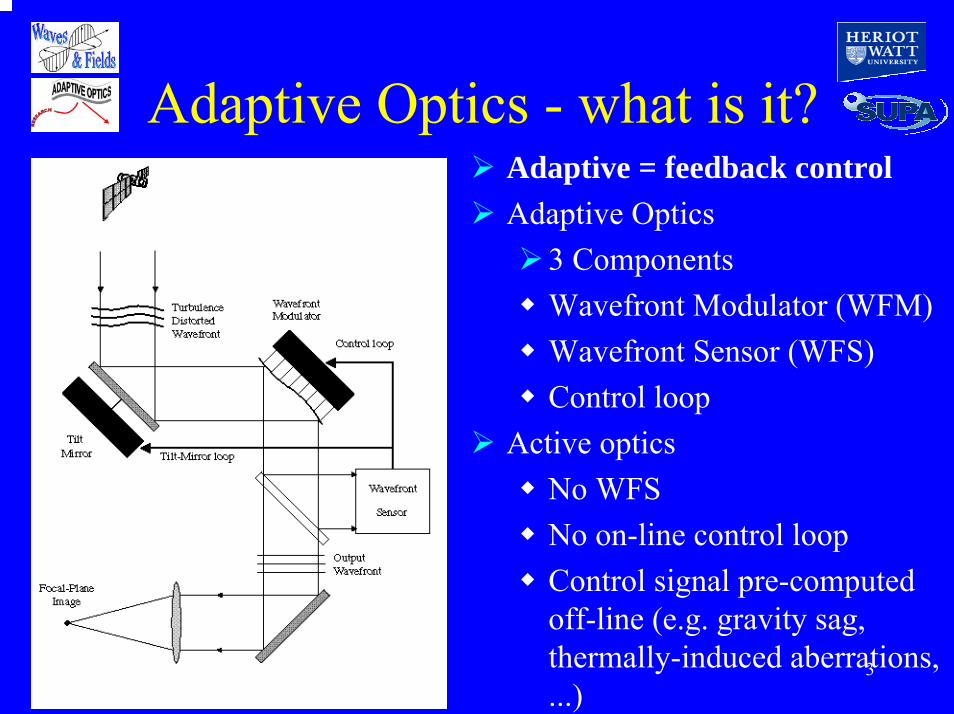
Adaptive Optics - what is it?Adaptive = feedback controlAdaptive Optics
3 ComponentsWavefront Modulator (WFM)Wavefront Sensor (WFS)Control loop
Active opticsNo WFSNo on-line control loopControl signal pre-computed off-line (e.g. gravity sag, thermally-induced aberrations, ...)
27 April 2005 4
Background• Adaptive optics
• Metrology
Null wavefront sensor is most suitable
fasterflexiblecheaper (?)
Require wavefront reconstruction
reference to national standardsspeed/cost less important (?)

27 April 2005 5
Metrology• Metrology is a
demanding application
• Speed also required...
• …as is robustness
NumbersEven worse, absolute numbers!Reference to standards!
Production lines for thin plastic films run at 5ms-1
Discontinuous surfacesRough surfacesMultiply-connected surfaces

27 April 2005 6
Err...• For industrial surfaces
• For thin films
• For exo-earth imaging
Sub nm resolution is generally sufficient
Sub Å resolution on wavefront aberrations is required
Better than 0.1 Å is required
An industrialist insisted that he needed a resolution of λ/40000

27 April 2005 7
How to achieve these...Unlikely to give accuracy or spatial format neededData reduction is time consumingEfficient use of data (not of detector)Can be reduced to a very simple algorithmCan be very accurateCan be large format
• Average over lenslet(Shack Hartmann)?
• Shearing interferometer?
• Wavefront curvature (phase diversity)?
27 April 2005 8
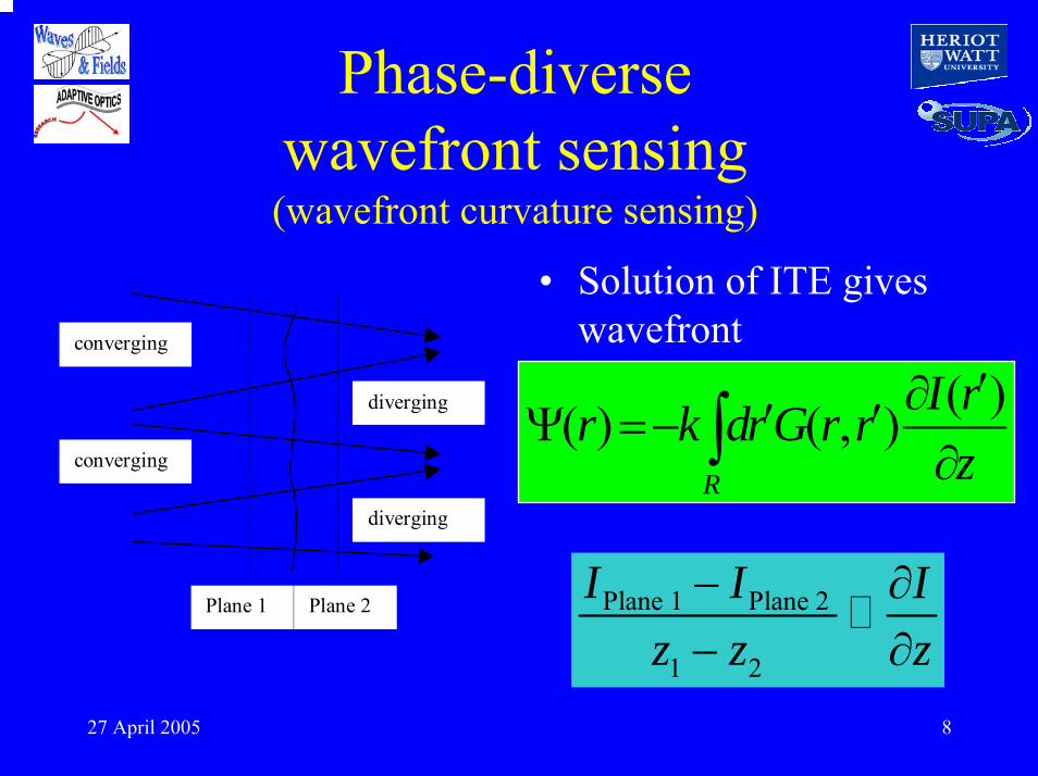
Phase-diverse wavefront sensing
(wavefront curvature sensing)
• Solution of ITE gives wavefrontconverging
converging
diverging
diverging
Plane 1 Plane 2
( )( ) ( , )R
I rr k dr G r rz′∂′ ′Ψ =−
∂∫
Plane 1 Plane 2
1 2
I I Iz z z− ∂− ∂

27 April 2005 9
Green’s function solution (GFS)
1 22 ( )I I GI z
π φλ δ
−⋅ ⋅ =-
1I 2I
10
20
30
40
10
20
30
40
-1
0
1
10
20
30
40
-1
-0.5
0
0.5
1
-1
-0.5
0
0.5
1
-0.1
-0.05
0
0.05
-1
-0.5
0
0.5
1
-1
-0.5
0
0.5
1
=

27 April 2005 10
How to get the data?
∆x
yx
d
dm2Shift Phase Local x
m∆
π=φ
Phase shift is of opposite sign in orders of opposite sign m.
• Use a diffraction grating as a beamsplitter• Use ‘Detour Phase’ to get different level of
defocus in each diffraction order.• Simultaneous multi-plane imaging on 1 CCD

27 April 2005 11
How to collect data?
)yx(R
dW)y,x( 22
220 +
λ=∆
φα r2phase change
φα − r2
r
+ 1
- 1
0
+1
0
-1
Parallel Beam
Converging Beam
Diverging Beam
Parallel BeamIncident
rR
DistortionW20 defines level of distortion. Equivalent to extra path length introduced at edge of grating aperture
W20 defines level of distortion. Equivalent to extra path length introduced at edge of grating aperture
r is radius from mask centre
r is radius from mask centre

27 April 2005 12
Diffractive Optics• Phase-diversity scheme needs wavefront intensity pattern
on two separate planes: Scheme adopted uses IMP®s
Undistorted Grating Undistorted Grating - identical images of a single object layer in each order
Distorted Grating Distorted Grating - images of different object layers on a single image plane
Diffraction Order-1 0 +1
IMAGE
IMP®
Image-1
0
+1-1 0 +1
Diffraction Order-1 0 +1IMP® is a DERA Trademark
DERA is now QinetiQ
27 April 2005 13
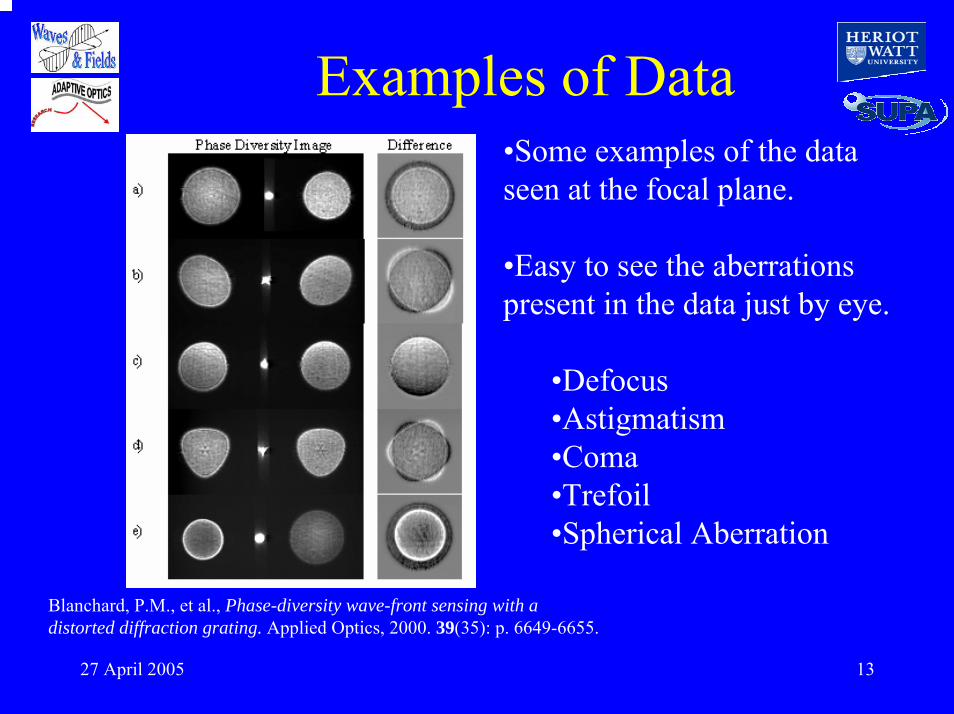
Examples of Data
Blanchard, P.M., et al., Phase-diversity wave-front sensing with a distorted diffraction grating. Applied Optics, 2000. 39(35): p. 6649-6655.
•Some examples of the data seen at the focal plane.
•Easy to see the aberrations present in the data just by eye.
•Defocus•Astigmatism•Coma•Trefoil•Spherical Aberration

27 April 2005 14
Phase Diverse WFS
• Solution of ITE gives wavefront
Plane 1 Plane 2
1 2
I I Iz z z− ∂− ∂
( )( ) ( , )R
I rr k dr G r rz′∂′ ′Ψ =−
∂∫Figure 1: Two intensity planes either side of the wavefront
• DoE used to image Planes 1 & 2

27 April 2005 15
RestrictionsPhase solution and its derivative must be continuous Wavefront must be simply connectedIntensity must be constant (or small variations)Deviation lead to low-pass filtered solutions
• Green’s function approach using Neumann boundary conditions

27 April 2005 16
Image Plane System
( )rψ
( ). .idr e pupilϕψ
1 { . . }i idI Ae e pupilϕ ϕ− ++ = ℑ
0{ } ( )th
iI Ae ϕ ξ= ℑ = Ψ
1 { . . }i idI Ae e pupilϕ ϕ− −− = ℑ
27 April 2005 17
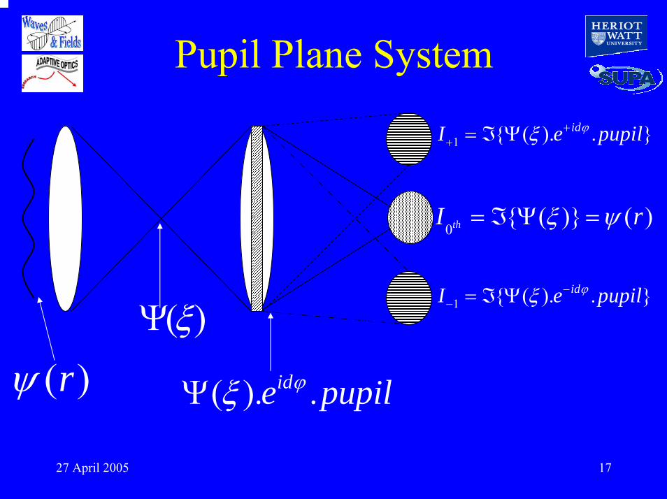
Pupil Plane System
( )rψ( )ξΨ
1 { ( ). . }idI e pupilϕξ ++ = ℑ Ψ
0{ ( )} ( )thI rξ ψ= ℑ Ψ =
1 { ( ). . }idI e pupilϕξ −− = ℑ Ψ
( ). .ide pupilϕξΨ
27 April 2005 18
Metrology requirementsMetrology of rough surfacesMetrology of printed circuits, integrated optics, ...Secondary with support structure
• Wavefront may be scintillated
• Wavefront may be discontinuous
• Wavefront may be multiply connected
All of these are a problem for the GFS approach

27 April 2005 19
Hang on...• Isn’t another way of looking at this as the
wavefront convolved with a defocused psf?• With a defocus symmetric wrt the plane in
which the wavefront is to be determined• So what, if anything, is special about
defocus?• Is the geometric picture just a prop?• What other convolutions might be used?
27 April 2005 20
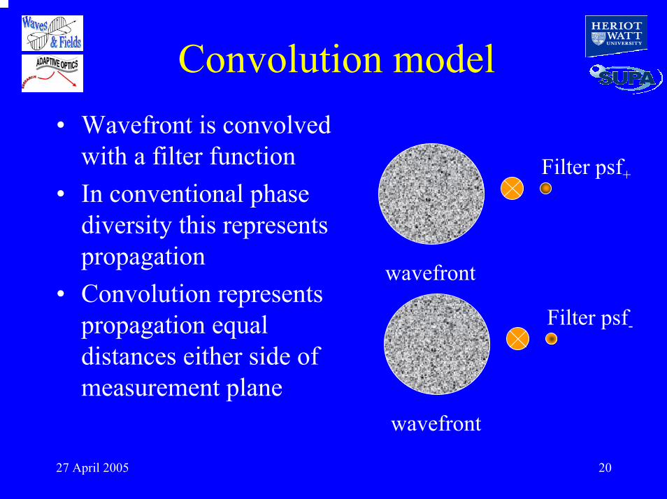
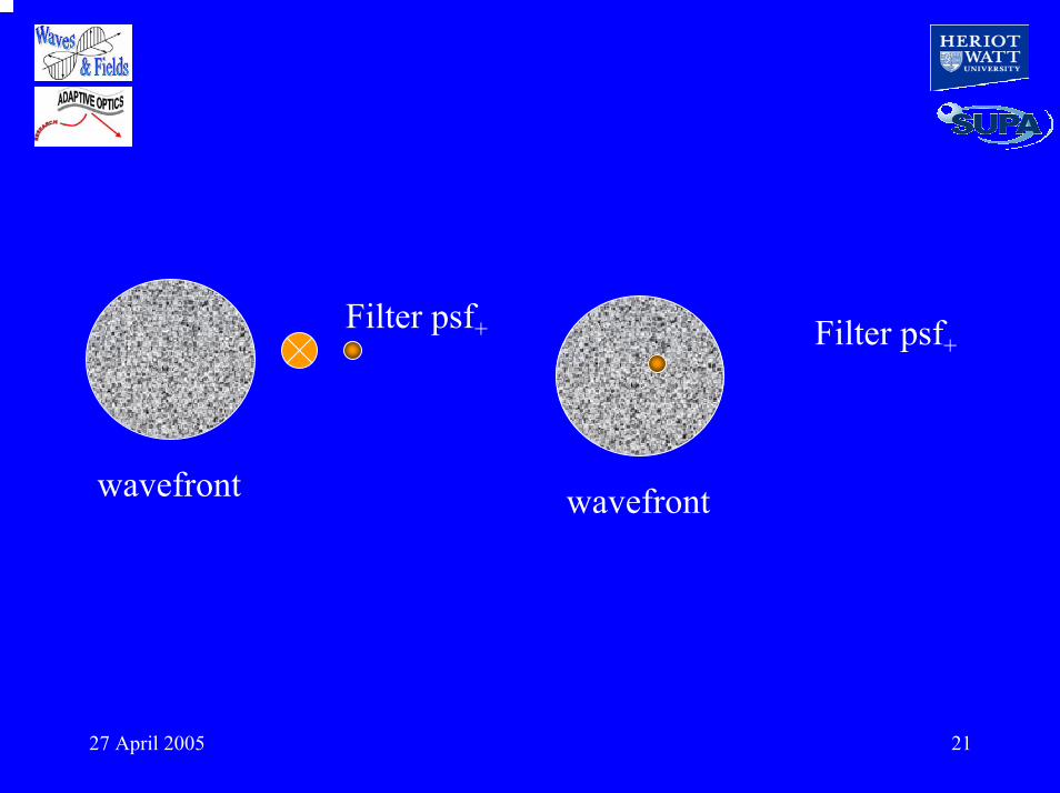
Convolution model• Wavefront is convolved
with a filter function• In conventional phase
diversity this represents propagation
• Convolution represents propagation equal distances either side of measurement plane
wavefront
Filter psf+
Filter psf-
wavefront
27 April 2005 21
wavefront
Filter psf+ Filter psf+
wavefront

27 April 2005 22
wavefront
Filter psf+ Filter psf+
wavefront

27 April 2005 23
wavefront
Filter psf+ Filter psf+
wavefront

27 April 2005 24
Null sensing• The basic requirement
for AO is a null sensorIt is sufficient, but not necessary, to have a metric that is zero if the wavefront is flatIt is desirable, but not necessary, to have a wfs that indicates the sense of any deviation from flatness

27 April 2005 25
Symmetry conditions• Required properties
for aberration functions are†:
† Campbell, Zhang, Greenaway and Restaino, Opt Lett, 29(2004)2707-2709
Filter function must be complexReal and imaginary parts must have same symmetryTwo filter function with opposite sense can be used to provide signal after subtraction
27 April 2005 26
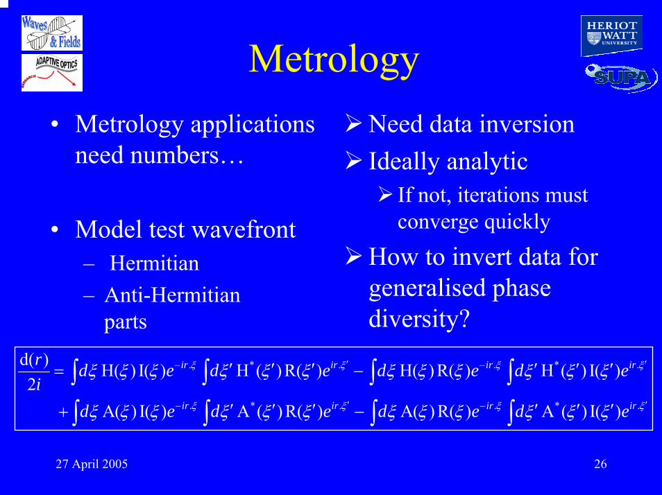
Metrology• Metrology applications
need numbers…
• Model test wavefront– Hermitian– Anti-Hermitian
parts
Need data inversionIdeally analytic
If not, iterations must converge quickly
How to invert data for generalised phase diversity?
. * . . * .
. * . . * .
d( ) H( ) I( ) H ( ) R( ) H( ) R( ) H ( ) I( )2
A( ) I( ) A ( ) R( ) A( ) R( ) A ( ) I( )
ir ir ir ir
ir ir ir ir
r d e d e d e d ei
d e d e d e d e
′ ′− −
′ ′− −
′ ′ ′ ′ ′ ′= −
′ ′ ′ ′ ′ ′+ −
∫ ∫ ∫ ∫∫ ∫ ∫ ∫
ξ ξ ξ ξ
ξ ξ ξ ξ
ξ ξ ξ ξ ξ ξ ξ ξ ξ ξ ξ ξ
ξ ξ ξ ξ ξ ξ ξ ξ ξ ξ ξ ξ
27 April 2005 27
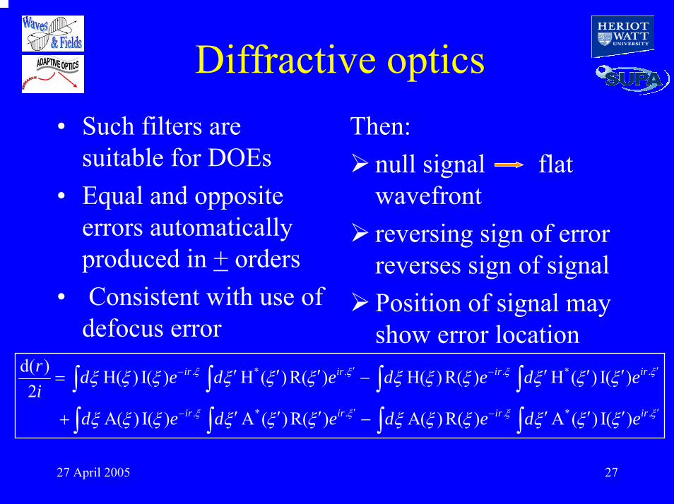
Diffractive optics• Such filters are
suitable for DOEs• Equal and opposite
errors automatically produced in + orders
• Consistent with use of defocus error
Then:null signal flat wavefrontreversing sign of error reverses sign of signalPosition of signal may show error location
. * . . *
. * . . *
d( ) H( ) I( ) H ( ) R( ) H( ) R( ) H ( ) I( )2
A( ) I( ) A ( ) R( ) A( ) R( ) A ( ) I(
ir ir ir
ir ir ir
r d e d e d e di
d e d e d e d
′ .
.)
ir
ir
e
e
′− −
′ ′− −
′ ′ ′ ′ ′ ′= −
′ ′ ′ ′ ′ ′+ −
∫ ∫ ∫ ∫∫ ∫ ∫ ∫
ξ ξ ξ ξ
ξ ξ ξ
ξ ξ ξ ξ ξ ξ ξ ξ ξ ξ ξ ξ
ξ ξ ξ ξ ξ ξ ξ ξ ξ ξ ξ ξ ξ

27 April 2005 28
Computer simulation• Same wavefront aberration with defocus and with
spherical aberration kernel• Can produce greater signal amplitude for same
signal input and same amplitude in kernel function
27 April 2005 29
Generalised phase diversityMany suitable filters, best signal wavefront dependentTried Gerchberg-Saxton - often hangsSuccessful with small signalsNow using SAE with iterative refinement
• Initially tested signal amplitude
• Generalised analytic solution hard
• Small-angle approximation
27 April 2005 30
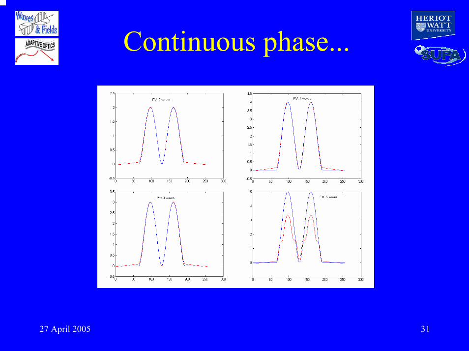
Continuous phase...
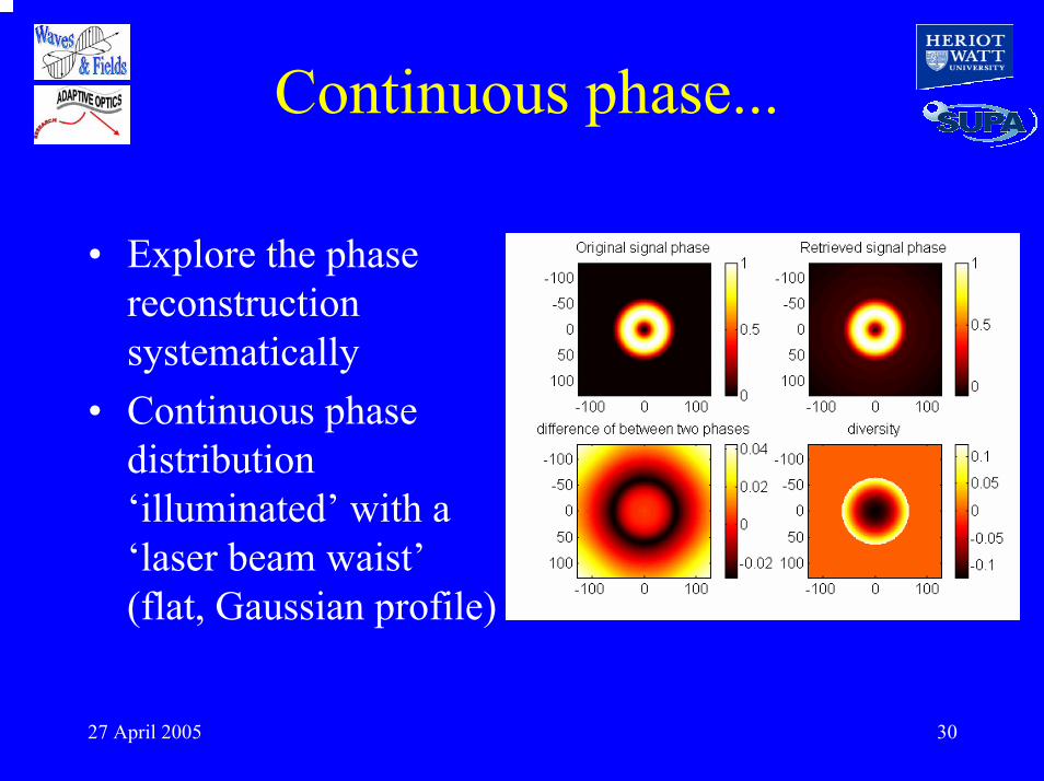
• Explore the phase reconstruction systematically
• Continuous phase distribution ‘illuminated’ with a ‘laser beam waist’(flat, Gaussian profile)
27 April 2005 31
Continuous phase...
27 April 2005 32
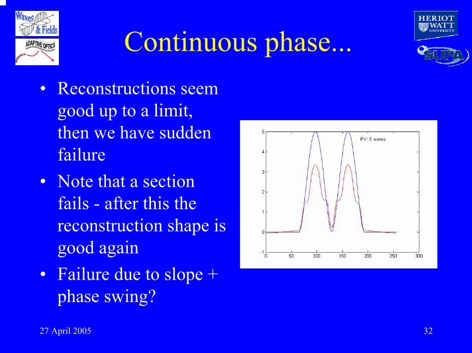
Continuous phase...• Reconstructions seem
good up to a limit, then we have sudden failure
• Note that a section fails - after this the reconstruction shape is good again
• Failure due to slope + phase swing?

27 April 2005 33
Limitations...• We are still trying to
determine how slope & amplitude combine to cause problem
• Hope to modify algorithm - but may need to modify diversity filter

27 April 2005 34
SAE
PV error of inputWavefront = 0.27λ
Defocus diversityUsed.
This figure shows the original input phase, and the retrieved phase calculated by the SAE algorithm. New data is computed from the solution and compared to the ‘measured’ data.An ‘error’ phase is calculated from the difference and used to iteratively refine the solution.
27 April 2005 35
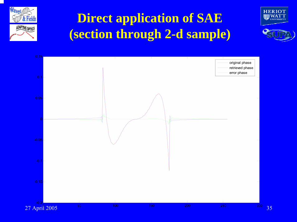
Direct application of SAE(section through 2-d sample)
0 50 100 150 200 250 300-0.2
-0.15
-0.1
-0.05
0
0.05
0.1
0.15
original phaseretrieved phaseerror phase
27 April 2005 36
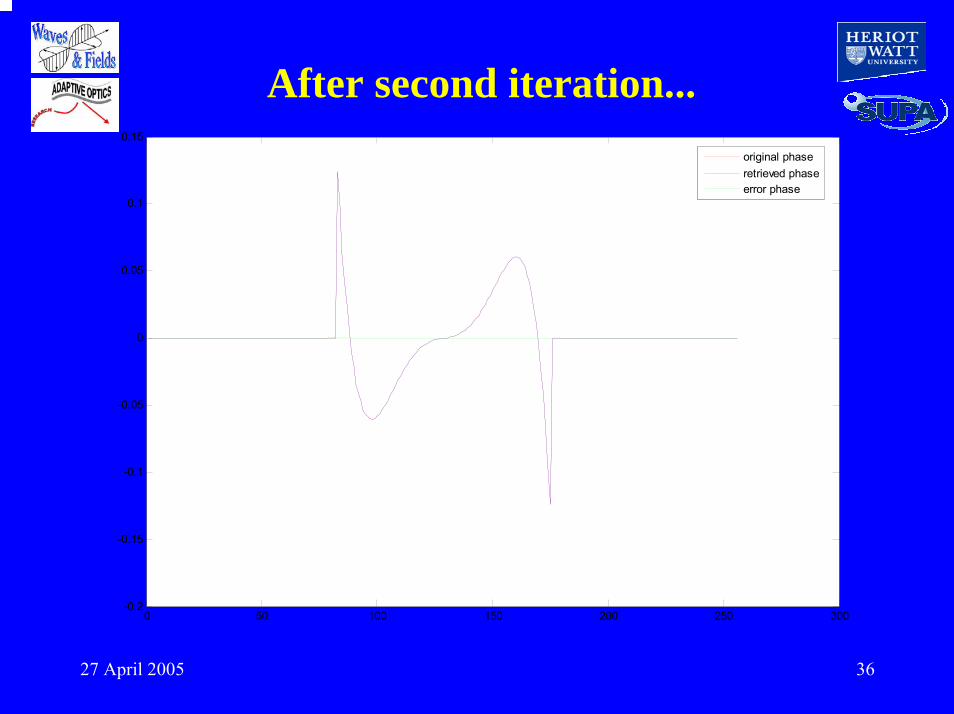
0 50 100 150 200 250 300-0.2
-0.15
-0.1
-0.05
0
0.05
0.1
0.15
original phaseretrieved phaseerror phase
After second iteration...

27 April 2005 37
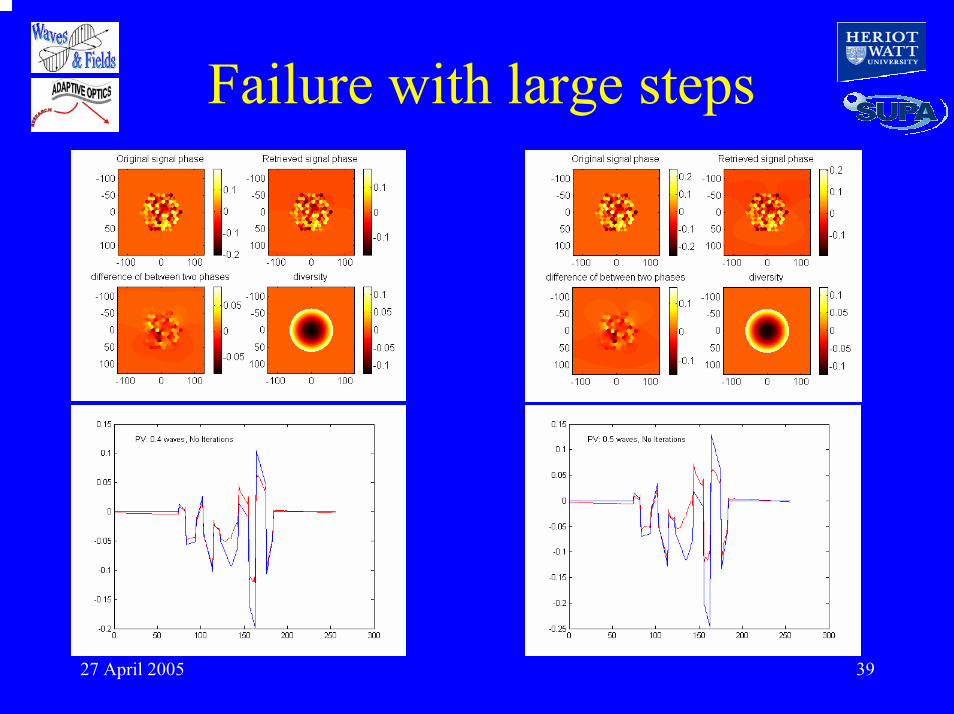
Discontinuous wavefrontsInitially a surprise, but verified by simulations‘No problem’ if step is <<π/2
• Theory suggests signal is null for π phase jump
• Small discontinuities reconstruct easily

27 April 2005 38
Problems with larger steps...
27 April 2005 39
Failure with large steps
27 April 2005 40
SummarySignal can be increased wrt defocusPossibility to optimise filter (using statistical model of zernike modes?)
Rapid convergence, cope with small discontinuities, speckle, multiple-connectivity?
• Phase diversity can be generalised
• Data inversion can be fast

27 April 2005 41
Summary• Completely analytic
solution not yet found• Is speed a problem
• Is increased sensitivity useful, or is need to optimise restricting?
• Is boundary-value problem solved?
Still considered desirable and sought forConvergence is fast and computation scales as NlogN, not N4 (GFS)If restricting, is defocus the best general choice?
Indication that this still requires more work


