Optical communications using orbitalangular momentum beamsA. E. Willner,1,* H. Huang,1 Y. Yan,1 Y. Ren,1 N. Ahmed,1 G. Xie,1
C. Bao,1 L. Li,1 Y. Cao,1 Z. Zhao,1 J. Wang,2 M. P. J. Lavery,3 M. Tur,4
S. Ramachandran,5 A. F. Molisch,1 N. Ashrafi,6 and S. Ashrafi6
1Department of Electrical Engineering at University of Southern California,Los Angeles, California 90089, USA
2Wuhan National Laboratory for Optoelectronics, School of Optical and ElectronicInformation, Huazhong University of Science and Technology,Wuhan 430074, Hubei, China
3School of Engineering, University of Glasgow, Glasgow G12 8QQ, Scotland, UK
4School of Electrical Engineering, Tel Aviv University, Ramat Aviv 69978, Israel
5Department of Electrical and Computer Engineering, Boston University, Boston,Massachusetts 02215, USA
Advances in Optics and Photonics 7, 66–106 (2015) doi:10.1364/AOP.7.000066 67
Optical communications using orbitalangular momentum beamsA. E. Willner, H. Huang, Y. Yan, Y. Ren, N. Ahmed, G. Xie,C. Bao, L. Li, Y. Cao, Z. Zhao, J. Wang, M. P. J. Lavery, M. Tur,S. Ramachandran, A. F. Molisch, N. Ashrafi, and S. Ashrafi
1. Introduction
Achieving higher data transmission capacity is one of the primary interests of theoptical communications community. This has led to the investigation of usingdifferent physical properties of a lightwave for data encoding and channeladdressing, including amplitude, phase, wavelength, and polarization. More re-cently, spatially orthogonal modes and spatial positions have been under intenseinvestigation. A typical method of increasing the transmission capacity in opticalcommunication systems is the multiplexing of multiple independent datachannels. For example, multiple independent data channels can be located ondifferent wavelengths, polarizations, or spatial channels, corresponding towavelength-division multiplexing (WDM), polarization-division multiplexing(PDM), and space-division multiplexing (SDM), respectively [1,2].
A special case of SDM is the utilization of orthogonal spatially overlapping andco-propagating spatial modes, known as mode-division-multiplexing (MDM)[1]. In such a case, each mode can carry an independent data channel, and theorthogonality enables efficient (de)multiplexing and low inter-modal crosstalkamong multiple modes. There are several different types of orthogonal modalbasis sets that are potential candidates for such MDM systems. One such set isorbital angular momentum (OAM) [3].
It is well known that a lightwave can be interpreted quantum mechanically andthus can be viewed to carry both spin angular momentum (SAM) and OAM [4].Contrary to SAM (e.g., circularly polarized light), which is identified by theelectric field direction, OAM can be interpreted to characterize the “twist” ofa helical phase front [5]. Owing to the helical phase structure, an OAM-carryingbeam usually has an annular “ring” intensity profile with a phase singularity atthe beam center. Depending on the discrete “twisting” rate of the helical phase,OAM beams can be quantified as different states, which are orthogonal whilepropagating coaxially.
This property allows OAM beams to be potentially useful in improving theperformance of optical communication systems. Specifically, OAM states couldbe used as a different dimension to create an additional set of data carriers in anSDM/MDM system [3]. Importantly, OAM multiplexing does not rely on thewavelength or polarization, indicating that OAM could be used in addition toWDM and PDM techniques to improve system capacity. Compared to otherMDM methods, OAM might have some implementation advantages stemmingfrom the circular symmetry of the modes, which make it well-suited for manyoptical component technologies.
Advances in Optics and Photonics 7, 66–106 (2015) doi:10.1364/AOP.7.000066 68
This paper will highlight recent advances in OAM-based communication sys-tems. We will describe several proof-of-concept experimental demonstrations ofOAM multiplexing for optical communications that have been reported both infree space [6] and optical fiber [7]. Additionally, technical challenges, such asthe atmospheric turbulence in free-space links and mode coupling in fiber linkswill be discussed. We will also review progress in the device technology forOAM generation, detection, and (de)multiplexing, as well as the design of novelfibers that are possibly more suitable for OAM transmission.
2. OAM and Light Beams
It is well known that different types of movement of an object are associated withdifferent types of momentum: an object moving in a straight line carries linearmovement. Angular momentum is imparted by spinning (i.e., SAM), or orbitingaround an axis (i.e., OAM), as shown in Figs. 1(a) and 1(b), respectively. A lightbeam may also possess these two types of angular momenta. In the paraxialapproximation, a light beam carries SAM if the electrical field rotates alongthe beam axis (i.e., circularly polarized light) and carries OAM if the wave vec-tor spirals around the beam axis, leading to a helical phase front, as shown inFigs. 1(c) and 1(d) [8]. In its analytic expression, this helical phase front is usu-ally related to a phase term of exp�ilθ� in the transverse plane, where θ refers tothe azimuthal coordinate and l is an integer counting the number of intertwinedhelices (i.e., the number of 2π phase shifts along the circle around the beamaxis). l is an integer and can therefore assume a positive, negative, or evena zero value, corresponding to clockwise or counterclockwise phase helicesor a Gaussian beam (i.e., no helix), respectively [9].
Two important concepts that sometimes give rise to confusion are dis-cussed below:
(1) OAM and polarization: As mentioned above, an OAM beam has a helicalphase front and therefore results in a twisting wavevector. On the other
Figure 1
Two cases of angular momenta: (a) a spinning object carrying SAM and (b) anorbiting object carrying OAM. (c) A circularly polarized light beam carryingSAM, and (d) the phase structure of an OAM-carrying light beam.
Advances in Optics and Photonics 7, 66–106 (2015) doi:10.1364/AOP.7.000066 69
hand, SAM is connected to polarization states. A light beam carries SAM of�h∕2π (h is Plank’s constant) per photon if it is left or right circularly po-larized and carries no SAM if it is linearly polarized. Although the SAM andOAM of light can be coupled to each other under certain scenarios [10],they can be clearly distinguished for a paraxial light beam. Therefore, inthe paraxial limit, OAM and polarization can be considered two indepen-dent properties of light [9].
(2) OAM beam and Laguerre–Gaussian (LG) beam: In general, an OAM-carrying beam could refer to any helically phased light beam, irrespectiveof its radial distribution. LG beams are a special subset among all OAM-carrying beams, whose radical distribution is characterized by the fact thatthey are paraxial eigensolutions of the wave equation in cylindrical coordi-nates and in homogeneous media (e.g., free space). For an LG beam, bothazimuthal and radial wavefront distributions are well defined and indicatedby two indices, l and p, in which l has the same meaning as that of a generalOAMbeam (i.e., azimuthal phase dependence) andp refers to the radial nodesin the intensity distribution. LG beams form an orthogonal and completemode in the spatial domain. In contrast, a general OAM beam may be ex-panded into agroupofLGbeams (eachwith the samelbut adifferentp index)due to the absence of radial definition. Henceforth, the term “OAM beam”
refers to all helically phased beams and is to be distinguished fromLGbeams.
3. Application of OAM to Optical Communications
Utilization of OAM for communications is based on the fact that coaxiallypropagating light beams with different OAM states can be efficiently separated.This is obviously true for orthogonal modes such as the LG beams. Interestingly,it also holds for general OAM beams with cylindrical symmetry by relying onlyon the azimuthal phase. Considering any two OAM beams having an azimuthalindex of l1 and l2, respectively,
U 1 � �r; θ; z� � A1�r; z� exp�il1θ�; (1)
U 2 � �r; θ; z� � A2�r; z� exp�il2θ�; (2)
where r refers to the radial position and z is the propagation distance, one canconclude that these two beams are orthogonal in the sense that
Z2π
0
U 1U�2 dθ �
�0 if l1 ≠ l2
A1A�2 if l1 � l2
: (3)
There are two different ways to take advantage of the distinction between OAMbeams with different l states in communications. In the first approach, N differ-ent OAM states can be encoded as N different data symbols representing“0”; “1”;…; “N − 1”. A sequence of OAM states sent by the transmitter there-fore represents data information. At the receiver, the data can be decoded bychecking the received OAM state. This approach seems to be more favorableto the quantum communications community, since OAM could provide for theencoding of multiple bits [log2�N�] per photon due to the infinitely countablenumber of possible OAM states, and so could potentially achieve higher photon
Advances in Optics and Photonics 7, 66–106 (2015) doi:10.1364/AOP.7.000066 70
efficiency [11]. The encoding/decoding of OAM states could also have somepotential applications for on-chip interconnection to increase data capacity [12].
The second approach, employed in most of the recent demonstrations, is to useeach OAM beam as a carrier for a different data stream [13]. A typical SDMsystem uses either a multicore fiber or free-space laser beam array so that thedata channels in each core/laser beam are spatially separated [14], or a group oforthogonal modes to carry different data channels in a multimode fiber (MMF)or in free space [15]. High capacity data transmissions in a multicore fiber and ina single-core MMF have been reported [16,17]. Similar to the second SDM ar-chitecture that uses copropagating orthogonal modes, OAM beams with differ-ent states can be spatially multiplexed and demultiplexed, thereby providingindependent data carriers in addition to wavelength and polarization. Ideally,the orthogonality of OAM beams can be maintained in transmission, which al-lows all the data channels to be separated and recovered at the receiver. A typicalscheme of OAM multiplexing is conceptually depicted in Fig. 2. An obviousbenefit of OAM multiplexing is the improvement in system spectral efficiency,since the same bandwidth can be reused for additional data channels [18].
Many approaches for creating OAM beams have been proposed and demon-strated. One could obtain a single or multiple OAM beams directly from theoutput of a laser cavity [19,20] or by converting a fundamental Gaussian beaminto an OAM beam outside a cavity. The converter could be a spiral phase plate[5], diffractive phase holograms [21–23], metamaterials [24–27], cylindricallens pairs [28], q-plates [29,30], fiber gratings [31], or couplers [32]. Thereare also different ways to detect an OAM beam, such as using a converter thatcreates a conjugate helical phase or using a plasmonic detector [33].
4.1a. Mode Conversion Approaches
Among all external-cavity methods, perhaps the most straightforward one is topass a Gaussian beam through a coaxially placed spiral phase plate (SPP) [34,35]or to have it reflected by a spiral phase mirror (SPM) [36]. An SPP is an opticalelement with a helical surface, as shown in Fig. 3(a). To produce an OAM beam
Figure 2
Conceptual schematic of a communication system employing OAMmultiplexing.
Advances in Optics and Photonics 7, 66–106 (2015) doi:10.1364/AOP.7.000066 71
with a state of l, the thickness profile of the plate should be machined aslλθ∕2π�n − 1�, with n being the refractive index of the medium (note that onlyhalf of the thickness variation is required if using an SPM). Such elements can befabricated with very high precision, and the generation of OAM beams with acharge as high as 5050 has been demonstrated [36]. As alternatives, reconfig-urable diffractive optical elements, e.g., a pixelated spatial light modulator(SLM), or a digital micromirror device [23] can be programmed to functionas a refractive element of choice at a given wavelength, as shown in Fig. 3(b).Importantly, the generated OAM beam can be easily changed by simply updat-ing the hologram loaded on the SLM. To spatially separate the phase-modulatedbeam from the zeroth-order non-phase-modulated beam at the SLM output, alinear phase ramp is added to the helical phase mask (i.e., a “fork”-like phasepattern, as shown in Fig. 3(c)) to produce a spatially distinct first-order diffractedOAM beam, carrying the desired charge [22]. It should also be noted that theaforementioned methods produce OAM beams by only modulating the phase ofthe incoming beam. To generate a high quality LGl;p mode, one must jointlycontrol both the phase and the intensity of the incoming beam. This can beachieved using a phase-only SLM with a more complex phase hologram [37].
Figure 3
Three approaches to convert a Gaussian beam into an OAM beam: (a) a spiralphase plate, (b) a phase hologram with a spiral phase pattern, or (c) a phasehologram with a “fork” pattern. In this example, the conversion to an OAMbeam with l � �3 is depicted.
Figure 4
Mid-infrared metasurface phase plate that can generate OAM beams. (a) Thefabricated metasurface phase plate. (b) Magnified structure of the designedmetasurface. (c) Interferogram of the generated OAM beam with l � �1.Reprinted from Yu et al., Science 334, 333–337 (2011) [24] by permission fromAAAS.
Advances in Optics and Photonics 7, 66–106 (2015) doi:10.1364/AOP.7.000066 72
Some novel material structures, such as metasurfaces, can also be used for OAMgeneration. A compact metasurface could be made into a phase plate by manipu-lating the spatial phase response caused by the structure [24,25]. As shown inFigs. 4(a) and 4(b), the metasurface is created by assembling an array of sub-wavelength antennas, each of which is composed of two arms connected at oneend. Light reflected by this plate experiences a phase change ranging from 0 to2π, determined by the length of the arms and their relative angle [24]. To gen-erate an OAM beam, the surface is divided into eight sectors, each of whichintroduces a phase shift from 0 to 7π∕4 with a step of π∕4. The OAM beamwith l � �1 is obtained after the reflection, as shown in Fig. 4(c).
Another interesting liquid-crystal-based device called a “q-plate” is also used toconvert a circularly polarized beam into an OAM beam [30]. A q-plate is essen-tially a liquid-crystal slab with uniform birefringent phase retardation of π and aspatially varying transverse optical axis pattern. Along the path circling oncearound the center of the plate, the optical axis of the distributed crystal elementsmay have a number of rotations defined by the value of q. A circularly polarizedbeam passing through this plate would experience a helical phase change ofexp�ilθ� with l � 2q, as shown in Fig. 5 [30].
Note that almost all of the mode conversion approaches can also be used todetect an OAM beam. For example, an OAM beam can be converted backto a Gaussian-like beam if the helical phase front is removed, e.g., by passingthe OAM beam through a conjugate SPP or phase hologram [5].
4.1b. Intra-cavity Approaches
OAM beams are higher order modes with respect to the Gaussian mode and canbe directly generated from a laser resonator cavity. A resonator supportinghigher order modes usually produces a mixture of multiple modes, includingthe fundamental mode. In order to avoid the resonance of the fundamentalGaussian mode, a typical approach is to place an intracavity element (e.g., anSPP or a mirror) to force the oscillator to resonate on a specific OAMmode [38].Other reported demonstrations include the use of an annular shaped beam as
Advances in Optics and Photonics 7, 66–106 (2015) doi:10.1364/AOP.7.000066 73
laser pump [39], the use of thermal lensing [40], or using a resonator mirror witha defect spot in the center [41].
Instead of using bulk free-space optics, a more compact version of an OAMbeam generator on the micrometer scale is reported using a modified microringresonator [42]. The idea is that whispering gallery modes can be excited andconfined in a ring resonator. To change it into an OAM beam emitter, angulargrating structures are embedded into the regular ring resonator to periodicallyvary the refractive index in the azimuthal direction, as shown in Fig. 6(a). Thegrating structure distributed along the ring cavity is used to create diffractions onthe guided mode in the ring resonator. The principle is similar to what a linearlydistributed grating does to the incoming light, as shown in Fig. 6(b). The dif-fracted beam from the side of the ring resonator possesses a helical phase front[Fig. 6(c)], the azimuthal state of which is determined by the difference betweenthe azimuthal order of the mode guided in the ring and the period of gratingelements in the ring. Tuning of the l state of the generated beam can be achievedby exciting different orders of guided modes in the ring, as discussed in [43].Fast switching between two different OAM states at the rate of 20 μs is dem-onstrated through the use of electrically contacted thermo-optical control. Due tothe miniaturized dimension, there is the potential of producing an array of suchOAM beam generators on a single photonic chip. A fabricated array includingthree identical ring resonators and their generated output beams is shown inFigs. 6(d1)–6(d3).
4.2. OAM Beams Multiplexing and Demultiplexing
One of the benefits of OAM is that multiple coaxially propagating OAM beamswith different l states provide additional data carriers, as they can be separatedbased only on the twisting wavefront. Hence, one of the critical techniques is theefficient multiplexing/demultiplexing of OAM beams of different l states, such
Figure 6
Vortex beam generator using a ring resonator embedded with circularly distrib-uted gratings [42]. (a) structure of the device. (b) distributed gratings in a linearwaveguide producing a tilted plane wave by diffraction. (c) schematic view ofthe on-chip OAM generator. (d1) three OAM emitters fabricated on a singlechip. (d2) OAM beams generated by using the emitter array and (d3) their in-terferograms. Reprinted from Cai et al., Science 338, 363–366 (2012) [42] bypermission from AAAS.
Advances in Optics and Photonics 7, 66–106 (2015) doi:10.1364/AOP.7.000066 74
that each carries an independent data channel and all beams can be transmitted andreceived using a single aperture pair. Several multiplexing and demultiplexingtechniques have been demonstrated, including the use of an inverse helical phasehologram to convert the OAM into a Gaussian-like beam, a mode sorter [44],free-space interferometers [45], a photonic integrated circuit [46–48], and q-plates[49]. Some of these techniques are briefly described below.
4.2a. Beam Splitter and Inverse Phase Hologram
A straightforward way of multiplexing different beams is to use cascaded 3 dBbeam splitters. Each beam splitter can coaxially multiplex two beams that areproperly aligned, and cascadedN beamsplitters canmultiplexN � 1 independentOAM beams at most, as shown in Fig. 7(a). Similarly, at the receiver end, themultiplexed beams are divided into four copies. To demultiplex the data channelon one of the beams (e.g., with l � li), a phase hologram with a spiral charge of−li is applied to all the multiplexed beams. As a result, the helical phase on thetarget beam is removed, and this beamwill eventually evolve into a Gaussian-likebeam. TheGaussian-like beam can be isolated from the other OAMbeams, whichstill have helical phase fronts, by using a spatial mode filter, e.g., a single-modefiber (SMF) at the focal point of a lens will couple the power only of the Gaussianmode due to the mode-matching constraints. Accordingly, each of the multi-plexed beams can be demultiplexed by changing the spiral phase hologram.Although the power loss incurred by the beam splitters and the spatial mode filtermakes this method quite power inefficient, it was frequently used in the initiallaboratory demonstrations of OAM multiplexing/demultiplexing due to its sim-plicity and reconfigurability provided by the programmable SLMs.
More power-efficient multiplexing and demultiplexing of OAM beams areachieved by using an OAM mode sorter [50,51]. This mode sorter usually com-prises three optical elements, namely, a transformer, a corrector, and a lens, asshown in Fig. 8 [52]. The transformer performs a geometrical transformation ofthe input beam from log-polar coordinates to Cartesian coordinates, such that theposition �x; y� in the input plane is mapped to a new position �u; v� in the outputplane, where u � −a ln
� ffiffiffiffiffiffiffiffiffix2�y2
pb
�and v � arctan�y∕x�. Here, a and b are scaling
constants. The corrector compensates for phase errors and ensures that the trans-formed beam is collimated. Considering an input OAM beam with a ring-shaped
Figure 7
Schematic depiction of spatial multiplexing and demultiplexing: (a) spatialmultiplexing using cascaded beam splitters (BS) and (b) demultiplexing usingcascaded beam splitters and conjugate SPPs (or phase holograms).
Advances in Optics and Photonics 7, 66–106 (2015) doi:10.1364/AOP.7.000066 75
beam profile, it can be unfolded and mapped into a rectangular-shaped planewave with a tilted phase front. Similarly, multiple OAM beams having differentl states will be transformed into a series of plane waves, each with a differentphase tilt. A lens focuses these tilted plane waves into spatially separated spots inthe focal plane such that all OAM beams are simultaneously demultiplexed.Since the transformation is reciprocal, the mode sorter can also be used in re-verse to function as an OAM generator and multiplexer. A Gaussian beam arrayplaced in the focal plane of the lens is converted into superimposed plane waveswith different tilts. These beams then pass through the corrector and the trans-former to produce properly multiplexed OAM beams [53].
4.2c. OAM Multiplexing/Demultiplexing Using PhotonicIntegrated Circuits
Integrated versions of an OAM (de)multiplexer were reported using planar pho-tonic waveguides [46–48]. The concept of such a device is schematically shownin Fig. 9 [48]. A group of single-mode waveguides interfaced with SMFs areplaced in parallel as the input ports. The beam from each input port is expandedto a plane wave with a phase tilt and is then sampled by a number of path-length-matched waveguides. The output apertures of all the waveguides are circularlyarranged. The coherent combination of output beams from each aperture couldevolve into an OAM beam, the state of which is determined by the position ofthe input port. In principle, such a device with N waveguide apertures can sup-port at most N different OAM states ranging from −N∕2 to N∕2 − 1. The simu-lated and experimentally observed OAM beams using a circuit with nineavailable apertures are shown in Fig. 9(b). Note that instead of being placedperpendicularly to the chip surface, the output aperture arrays could also be ar-ranged laterally in a 3D structure, as shown in Fig. 9(c). This device was dem-onstrated and used in a free-space optical communication link utilizing twomultiplexed OAM states, as described by Guan et al. [54].
The (de)multiplexing approaches discussed above operate on the OAM beamssuch that OAM beams are transformed into non-OAM beams and vice versa.There also exists a scheme that performsOAM(de)multiplexingwithout perform-ing mode transformation such that the OAM property is maintained even afterperforming the desired operation. Such a method uses free-space interferometers
Figure 8
Concept of an OAM mode sorter. The log-polar geometrical-transformation-based mode sorter can be used as an OAM multiplexer (when light propagatesfrom right to left) and a demultiplexer (when light propagates from left to right).
Advances in Optics and Photonics 7, 66–106 (2015) doi:10.1364/AOP.7.000066 76
withDove prisms to efficiently (de)multiplexOAMbeams [45].Wenote that bothtypes of demultiplexing methods could be useful in optical communications.
5. Free-Space Optical Communications Using OAM
The first proof-of-concept experiment using OAM for free-space communica-tions was reported by Gibson et al. in 2004 [3]. In their demonstration, eightdifferent OAM states, each representing a data symbol, were transmitted one ata time. The azimuthal index of the transmitted OAM beam was measured at thereceiver using a phase hologram modulated with a binary grating, demonstratingthat information transfer can be achieved. To effectively use this approach, fastswitching is required between different OAM states to achieve a high data rate.Alternatively, there has been progress in classical communications by usingOAM states as data carriers, which can be multiplexed at the transmitter,copropagate through the free-space link, and be demultiplexed at the receiver[55–57]. The total data rate of a free-space communication link demonstratedin the laboratory experiments has reached 100 Tbit∕s or even beyond by usingOAMmultiplexing [58,59]. The propagation of OAM beams through the atmos-phere (e.g., across a city) is also under investigation and related discussion canbe found in the experiments reported in [60,61].
Initial demonstrations of using OAM multiplexing for optical communicationsinclude free-space links using a Gaussian beam and an OAM beam encoded with
Figure 9
OAMmultiplexing/demultiplexing using photonic integrated circuit: (a) conceptand principle, and (b) simulated and experimentally generated OAM beams(l � �2, �3, and �4) using the photonic integrated circuit shown in (a). Re-printed with permission from [48]. Copyright 2012 Optical Society of America.(c) Conceptual schematic of the 3D integrated device for OAMmultiplexing anddemultiplexing. Reprinted with permission from [54]. Copyright 2014 OpticalSociety of America.
Advances in Optics and Photonics 7, 66–106 (2015) doi:10.1364/AOP.7.000066 77
on–off keying data [55]. Later on, the multiplexing/demultiplexing of fourdifferent OAM beams in a free-space data link was reported by Wang et al. [56].Four monochromatic Gaussian beams each carrying an independent 50.8 Gbit∕s(4 × 12.7 Gbit∕s) 16-QAM signal were prepared from an IQ modulator and free-space collimators. Then they were converted to OAM beams with l � −8,�10,�12, and −14, using four SLMs each loaded with a helical phase hologram, asshown in Fig. 10(a). After being coaxially multiplexed using cascaded 3 dB beamsplitters, the beams propagate through ∼1 m distance in free space under labo-ratory conditions. The OAM beams were then detected one at a time, using aninverse helical phase hologram and a fiber collimator together with an SMF.The 16-QAM data on each channel were successfully recovered, and a spectralefficiency of 12.8 bit∕s∕Hz in this data linkwas achieved, as shown in Figs. 10(b)and 10(c).
A following experiment doubled the spectral efficiency by adding polarizationmultiplexing into the OAM-multiplexed free-space data link. Four differentOAM beams (l � �4, �8, −8, and �16) on each of two orthogonal polariza-tions (eight channels in total) were used to achieve a terabit/second transmissionlink. The eight OAM beams were multiplexed and demultiplexed using the sameapproach as mentioned above. The measured crosstalk among channels carriedby the eight OAM beams is shown in Table 1, with the largest crosstalk beingabout −18.5 dB. Each of the beams was encoded with a 42.8 Gbaud 16-QAMsignal, allowing a total capacity of ∼1.4�42.8 × 4 × 4 × 2� Tbit∕s [6].
Figure 10
Experimental results of a free-space optical data link multiplexed with fourOAM beams. (a) Intensity profile of the four OAM beams generated(l � −8,�10,�12, and −14) and their superposition. (b) The optical spectrumof each channel after demultiplexing. (c) The recovered constellations of the16-QAM signals carried on each OAM beam. Reprinted with permission from[56]. Copyright 2011 Optical Society of America.
Advances in Optics and Photonics 7, 66–106 (2015) doi:10.1364/AOP.7.000066 78
The capacity of the free-space data link was further increased to 100 Tbit∕s bycombining OAMmultiplexing with PDM andWDM [58]. In this experiment, 24OAM beams (l � �4, �7, �10, �13, �16, and �19, each with two polar-izations) were prepared using two SLMs, the procedures for which are shown inFigs. 11(a1)–11(a3). Specifically, one SLM generated a superposition of OAMbeams with l � �4,�10, and�16, while the other SLM generated another setof three OAM beams with l � �7, �13, and �19. These two outputs weremultiplexed together using a beam splitter, thereby multiplexing six OAMbeams: l � �4, �7, �10, �13, �16, and �19. Second, the six multiplexedOAM beams were split into two copies. One copy was reflected five times bythree mirrors and two beam splitters, to create another six OAM beams withinverse charges. A differential delay between the two light paths decorrelatedtheir data. These two copies were then combined again to achieve 12 multi-plexed OAM beams with l � �4, �7, �10, �13, �16, and �19. These 12OAM beams were split again via a beam splitter. One of these was polarizationrotated by 90 deg, delayed by ∼33 symbols, and then recombined with the othercopy using a polarization beam splitter (PBS), finally multiplexing 24 OAMbeams (with l � �4, �7, �10, �13, �16, and �19 on two polarizations).Each beam carried a WDM signal comprising 100 GHz spaced 42 wavelengths(1536.34–1568.5 nm), each of which was modulated with 100 Gbit∕s quadra-ture phase-shift keying (QPSK) data. The observed optical spectrum of theWDM signal carried on one of the demultiplexed OAM beams (l � �10) isshown in Fig. 11(b).
Table 1. Measured Crosstalk of Each OAM Beam after Demultiplexing [dB]
−26.7 −30.8 −30.5 −27.7 −24.6 −30.1Y-Pol. −25.7 NA
l � �8X-Pol.
−26.6 −23.5NA −21.6
−18.9 −25.4 −23.9 −28.8Y-Pol. −25.0 NA
l � −8X-Pol.
−27.5 −33.9 −27.6 −30.8NA −20.5
−26.5 −21.6Y-Pol. −26.8 NA
l � �16X-Pol.
−24.5 −31.2 −23.7 −23.3 −25.8 −26.1NA −30.2
Y-Pol. −24.0 NATotal from other OAM beams −21.8 −21.0 −21.2 −21.4 −18.5 −21.2 −22.2 −20.7
Figure 11
(a) Three steps to produce 24 multiplexed OAM beams using two SLMs, mir-rors, beam splitters, a half-wave plate and a PBS. (b) The optical spectrum of theWDM signal carried on an OAM beam with l � �10. Reprinted with permis-sion from [58]. Copyright 2014 Optical Society of America.
Advances in Optics and Photonics 7, 66–106 (2015) doi:10.1364/AOP.7.000066 79
5.2. Atmospheric Turbulence Effects on OAM Beams
One of the critical challenges for a practical free-space optical communicationsystem using OAM multiplexing is atmospheric turbulence [62,63]. It is knownthat inhomogeneities in the temperature and pressure of the atmosphere lead torandom variations in the refractive index along the transmission path, and caneasily distort the phase front of a light beam [64,65]. This could be particularlyimportant for OAM communications, since the separation of multiplexed OAMbeams relies on the helical phase front. As predicted by simulations in the liter-ature, these refractive index inhomogeneities may cause intermodal crosstalkamong data channels with different OAM states [66–68].
The effect of atmospheric turbulence was also experimentally evaluated. For theconvenience of estimating the turbulence strength, one approach was to emulatethe turbulence in the laboratory by using an SLMor a rotating phase plate [69,70].Figure 12(a) illustrates the concept of an emulator built using a thin phase screenplate that is mounted on a rotation stage and placed in the middle of the opticalpath. The pseudorandom phase distribution machined on the plate obeysKolmogorov spectrum statistics, which are usually characterized by an effectiveFried coherence length r0 [71,72]. The strength of the simulated turbulence can bevaried either by using a plate with a different r0, or by adjusting the size of thebeam that is incident on the plate. The resultant turbulence effect is mainly evalu-ated bymeasuring the power of the distorted beam distributed to eachOAMmodeusing anOAMmode sorter. It was found that, as the turbulence strength increases,the power of the transmitted OAMmode starts to leak to neighboring modes andtends to be equally distributed among modes for strong turbulence. As an exam-ple, Fig. 12(b) shows the measured average power (normalized) of l � �3 beamunder different emulated turbulence conditions. It can be seen that the majority ofthe power is still in the transmitted OAM mode under weak turbulence, but itspreads to neighboring modes as the turbulence strength increases.
5.3. Turbulence Effects Mitigation Techniques
One possible approach to mitigate the effects of atmospheric turbulence on OAMbeams is to use an adaptive optical (AO) system.The general idea of anAOsystemis to measure the phase front of the distorted beam first, based on which an errorcorrection pattern is produced and applied onto the beam to undo the distortion.As
Figure 12
(a) A rotating phase plate is used as an atmospheric turbulence emulator. Anideal OAM beam emerges as a distorted OAM after passing through the phaseplate. (b) Measured power distribution of an OAM beam after passing throughthe turbulence emulator with different strengths. Reprinted with permission from[70]. Copyright 2013 Optical Society of America.
Advances in Optics and Photonics 7, 66–106 (2015) doi:10.1364/AOP.7.000066 80
for OAMbeamswith helical phase fronts, it is challenging to directly measure thephasefrontusingtypicalwavefrontsensorsduetothephasesingularity.AmodifiedAOsystemcanovercomethisproblembysendingaGaussianbeamasaprobebeamto sense the distortion [73], as shown in Fig. 13(a). Due to the fact that turbulenceeffects are almost independent of the light polarization [64], the probe beam isorthogonally polarized as compared to all of theother beams so that it is convenientto separate it at the receiver end. The correction phase pattern can be derived basedontheprobebeamdistortion,which isdirectlymeasuredbyawavefront sensor. It isnoted that this phase correction pattern can be used to simultaneously compensatemultiple coaxially propagating OAM beams. Figures 13(b1)–13(b3) and 13(b4)–13(b6) illustrate the intensity profiles of OAM beams with l � �1, +5, and +9,respectively, for a random turbulence realization with and without mitigation.From the far-field images, one can see that the distorted OAM beams (upper),up to l � �9, were partially corrected, and the measured power distribution alsoindicates that the channel crosstalk can be reduced.
As an alternative approach for combating turbulence effects, one could partiallymove the complexity of the optical setup into the electrical domain, and use digitalsignal processing (DSP) to mitigate the channel crosstalk. A typical DSP methodis blind multiple-input–multiple-output (MIMO) equalization, which is able toblindly estimate the channel crosstalk and cancel the interference [74]. The im-plementation of a 4 × 4 adaptive MIMO equalizer in a four-channel OAMmulti-plexed free-space optical link using heterodyne detection was described in [75].Four OAM beams (l � �2, �4, �6, and �8), each carrying 20 Gbit∕s QPSKdata, are collinearly multiplexed and propagated through weak turbulence emu-lated by the rotating phase plate under laboratory conditions. After demultiplex-ing, four channels are coherently detected and recorded simultaneously. Thestandard constant modulus algorithm [76] is employed in addition to the standardprocedures of coherent detection to equalize the channel interference. Results in-dicate that MIMO equalization could be helpful to mitigate the crosstalk causedby either turbulence or imperfect mode generation/detection, and to improve both
Figure 13
A feedback loop including a wavefront sensor and a wavefront corrector can beused to partially compensate the turbulence-induced distortions. (a) Concept offeedback loop of the wavefront compensator. (b) Experimental results of thewavefront compensation. (b1)–(b3) Distorted OAM beams with l � �1,�5, and �9. (b4)–(b6) Distortion mitigation using adaptive optics. Reprintedwith permission from [73]. Copyright 2014 Optical Society of America.
Advances in Optics and Photonics 7, 66–106 (2015) doi:10.1364/AOP.7.000066 81
the error vector magnitude (EVM) and the bit-error rate (BER) of the signal in anOAM-multiplexed communication link. It should be noted thatMIMODSP is notuniversally useful, as outage could happen in some scenarios involving free-spacedata links. For example, most of the power of the transmitted OAMbeamsmay betransferred to other OAM states under strong turbulence without being detected,in which case MIMO would not help to improve system performance [77].
5.4. OAM Free-Space Link Design Considerations
To date,many of the experimental demonstrations of optical communication linksusing OAM beams have taken place under laboratory conditions. Due tothe unique beam profile of OAM beams, challenges exist for designing a free-space optical communication link with a longer distance. Several important is-sues, such as beam divergence, aperture size, and misalignment of transmitterand receiver, need to be carefully considered. To study how those parametersaffect the performance of an OAM multiplexed system, a simulation modelwas described byXie et al. [78], the schematic setup of which is shown in Fig. 14.Different collimated data-carrying Gaussian beams having the same wavelengthare followed by SPPs with a unique order to convert the Gaussian beam into adata-carrying OAM beam. Different orders of OAM beams are then multiplexedto form concentric rings and coaxially propagate through free space to the receiveraperture located at a certain propagation distance. Propagation of multiplexedOAM beams is numerically calculated using the Kirchhoff–Fresnel diffractionintegral [79]. To investigate the signal power and crosstalk effects on neighboringOAM channels, power distribution among different OAM modes is analyzedthrough a modal decomposition approach, which corresponds to the case wherethe received OAM beams are demultiplexed without power loss and the power ofa desired OAM channel is completely collected by its receiver [80].
5.4a. Beam Divergence
Foracommunication link, it isgenerallypreferred tocollect asmuchsignalpoweraspossible at the receiver to ensure a sufficient signal-to-noise ratio (SNR). Based ondiffraction theory, it is known that a collimated OAM beam diverges while propa-gating in free space.Given the same spot sizeof 3 cmat the transmitter (here the spotsize of theOAMbeam is defined basedon the intensity profile [81]), anOAMbeamwith a higher azimuthal index diverges even faster, as shown in Fig. 15(a). Besidesthe index l, the received beam size is also related to the beam waist size at the
Figure 14
Schematic diagram of the modeled free-space optical data link employing OAMmultiplexing.
Advances in Optics and Photonics 7, 66–106 (2015) doi:10.1364/AOP.7.000066 82
transmitter, wavelength λ, and propagation distance z [82]. Figure 15(b) shows thespot size of different OAM beams at the receiver as a function of the transmittedbeam sizes over a 100 m link. Clearly, the received beam size is not a monotonicfunction of the beam size at the transmitter. For each OAM beam, there is a trans-mitter beam size that corresponds to a minimum value of diffraction-limited radiusafter propagating for100m.On theotherhand, the receivingoptical elementusuallyhas a limited aperture size andmaynot be able to collect all of the beampower.Notethat for each individualOAMmode, there is aminimumrequirement of the receivedpower, which ismainly related to two factors. (a) The sensitivity of the receiver: thereceiverneeds to receiveenoughpower toguaranteea sufficientSNR. (b)Thecross-talk from all of the other modes: the receiver needs to receive enough power in thedesired mode to guarantee a sufficient signal-to-interference ratio [83]. The calcu-lated link power loss as a function of receiver aperture size is shown in Fig. 15(c),with different transmission distances and various transmitted beam sizes. As ex-pected, the power loss of a 1 km link is higher than that of a 100 m link for thesame transmitted beam size due to the larger beam divergence. It is interestingto note that a system with a transmitted beam size of 3 cm suffers less power lossthan thatof1and10cmovera100mlink.The1cmtransmittedbeamdiverges fasterthan the 3 cmdue to its larger diffraction.However, when the transmitted beam sizeis 10 cm, the geometrical characteristics of the beam dominate over the diffraction,thus leading to a spot size at the receiver larger than that of the 3 cm transmittedbeam. A trade-off between the diffraction and geometrical characteristics of thebeam therefore needs to be carefully considered in order to achieve a proper sizereceived beam when designing a link.
5.4b. Misalignment Tolerance
Besides the power loss due to a limited size aperture and beamdivergence, anotherissue that needs further discussion is the potential misalignment between thetransmitter and the receiver, which can lead to both power loss and modalcrosstalk. In an ideal OAM multiplexed communication link, the transmitter
Advances in Optics and Photonics 7, 66–106 (2015) doi:10.1364/AOP.7.000066 83
and receiver would be perfectly aligned (i.e., the center of the receiver wouldoverlap with the center of the transmitted beam, and the receiver plane wouldbe perpendicular to the line connecting their centers, as shown in Fig. 16(a)).However, due to jitter and vibration of the transmitter/receiver platform, the trans-mitter and receiver may have relative lateral shift (i.e., lateral displacement) orangular shift (i.e., receiver angular error), as depicted in Figs. 16(b) and 16(c),respectively [84]. Both types of misalignment may lead to degradation of systemperformance.
For a link distance of 100 m, Figs. 17(a) and 17(b) show the power distributionamong different OAM modes due to lateral displacement and receiver angularerror when only l � �3 is transmitted with a transmitted beam size of 3 cm.In order to investigate the effect of misalignment, the receiver aperture size ischosen to be 4.5 cm, which could cover the whole OAM beam at the receiver.As the lateral displacement or receiver angular error increases, power leakage toother modes (i.e., channel crosstalk) increases while the power on l � �3 statedecreases. This is because larger lateral displacement or receiver angular errorcauses a larger phase profile mismatch between the received OAM beams andreceiver. The power leakage to l � �1 and l � �5 is smaller than that of l ��2 and l � �4 due to their larger mode spacing with respect to l � �3. There-fore, a system with larger mode spacing (which also uses higher order OAMstates) has less crosstalk. However, such a system may also have a larger powerloss due to the fast divergence of higher order OAM beams, as discussed above.Clearly, this trade-off between channel crosstalk and power loss shall be consid-ered when choosing the mode spacing in a specific OAM multiplexed link.
To show the angular error lateral shift effects under different propagation dis-tances, the ratio of the received power on OAM+4 to the received power onOAM+3 when only OAM+3 is transmitted is analyzed as an example [78].For simplicity, such a ratio is named XT-1. Figures 17(c) and 17(d) showXT-1 as functions of lateral displacement and receiver angular error for varioustransmission distances and transmitted beam sizes. As can be seen from the fig-ure, a larger beam size at the receiver will result in two opposing effects: (i) asmaller lateral-displacement-induced crosstalk (because the differential phase-change per unit area is smaller) and (ii) a larger tilt-phase-error-induced crosstalk(because the phase error scales with a larger optical path delay).
Advances in Optics and Photonics 7, 66–106 (2015) doi:10.1364/AOP.7.000066 84
5.5. Longer Distance OAM Beam Propagation in FreeSpace
In addition to simulation studies, experimental demonstrations of OAM beamspropagating over longer distances has also been reported [60]. In this experi-ment, multiplexed OAM beams were used to transfer information over a 3 kmintracity link in Vienna under a strong turbulence condition. As shown in Fig. 18,from the top of widely spaced buildings in Vienna, the Austrian group trans-mitted data bits representing a gray-scale image of Mozart such that each imagepixel was sequentially transmitted on one of 16 different OAM modes(l � �0;�1;…� 15). Each OAM mode is carried by a light beam at a wave-length of 532 nm. An incoherent detection scheme is used by directly observingthe unambiguous mode-intensity patterns on a screen with the help of a standardadaptive pattern recognition algorithm, and indeed, the image of the treasuredcomposer was successfully recovered, with an average error rate of ∼1.7%.
6. Optical Fiber Communications Using OAMMultiplexing
Optical fiber forms the worldwide backbone of high-capacity wired communica-tions. Therefore, it is valuable to determine the feasibility and practicality ofemployingOAM in fiber [85].OAMmodes are essentially a group of higher ordermodes defined on a different basis as compared to the other forms of modes infiber, such as linearly polarized (LP) modes and fiber vector modes. In principle,each of the modal sets forms an orthogonal mode basis spanning the spatial do-main, and could be used to transmit different data channels. Both LP modes andOAMmodes face challenges of mode coupling when propagating in a fiber, andmay also cause channel crosstalk problems.
In general, two approaches could be utilized in fiber transmission using OAMmultiplexing. The first such approach is to implement OAM transmission in aregular few-mode fiber (FMF). As is the case of SDM using LP modes, MIMO
Figure 17
(a),(b) Simulated power distribution among differentOAMmodes as a function oflateral displacement/receiver angular error over a 100-m link for which only theOAM� 3 is transmitted. The transmitted beam size is 3 cm and the receiver aper-ture size is 4.5 cm. (c),(d) XT-1 as functions of lateral displacement/receiver an-gular error for different transmission distances with different transmitted beamsizes. The receiver size is 1.5 times the transmitted beam size. XT-1, the ratioof the received power on OAM+4 to the received power on OAM+3; Dt, trans-mitted beam size; z, transmission distance.
Advances in Optics and Photonics 7, 66–106 (2015) doi:10.1364/AOP.7.000066 85
DSP is generally required to equalize themodal crosstalk. The second approach isto utilize a specially designed vortex fiber that has less mode coupling, and DSPequalization can therefore be avoided for a relatively short transmission distance.
6.1. OAM Transmission in Regular Few-Mode Fiber
In light of MDM in FMFs, LP modes have been used to achieve impressiveresults [1,2]. However, it might be valuable to explore different forms of modebasis that could exist in FMFs. In a regular FMF, each OAM mode representsapproximately a linear combination of the true fiber modes (the eigensolutions tothe wave equation in the fiber). For example, an LP OAM beam with l � �1
comprises the components of eigenmodes including TE01, TM01, and the twoHE21 modes. Due to perturbations or other nonidealities, the OAM modes thatare launched into a FMFmay quickly couple to each other, and this mutual modecoupling may lead to interchannel crosstalk and eventually failure of the trans-mission. One possible solution for the mode coupling effects is to use MIMODSP in combination with coherent detection.
A recent experiment demonstrated the transmission of four OAM beams(l � �1 and −1, each with two orthogonal polarization states), each carrying20 Gbit∕s QPSK data, in an ∼5 km regular FMF [53]. As shown in Fig. 19(a),four data channels (two with x polarization and two with y polarization) wereconverted to polarization multiplexed OAM beams with l � �1 and −1 using amode sorter (discussed in Section 4.2b) in the reverse direction. The two polari-zation multiplexed OAM beams (four in total) were coupled into the FMF forpropagation. At the fiber output, the received modes were decomposed into an
Figure 18
Experimental demonstration of the free-space propagation of OAMbeams acrossthe city of Vienna. ZAMG: transmitter building (Zentralanstalt für Meteorologieund Geodynamik, Central Institute for Meteorology and Geodynamics). IQOQI:receiver building. Top: picture of an alignment laser from IQOQI to ZAMG, cap-tured at ZAMG. Left: the sender modulates a 532 nm laser with an SLM. Thedifferent phase holograms that modulate the beam are shown; they correspondto superpositions of OAM modes (from top to bottom) with l � �1, l � �1
Advances in Optics and Photonics 7, 66–106 (2015) doi:10.1364/AOP.7.000066 86
OAMmode basis (l � �1 and −1) using another mode sorter. Then each of thetwo OAM components of light was coupled into a fiber-based PBS for polari-zation demultiplexing. Each output was detected by a photodiode, followed byan analog-to-digital converter and offline processing. To mitigate the interchan-nel interference, the constant modulus algorithm was used to blindly estimate thechannel crosstalk and compensate for it using linear equalization. Eventually, theQPSK data carried on each OAM beam was recovered with the assistance ofMIMO DSP, as shown in Figs. 19(b) and 19(c).
6.2. OAM Transmission in a Vortex Fiber
The major reason for power exchange (i.e., coupling) between two modes duringtransmission through a conventional fiber is the relatively small difference be-tween their effective refractive indices (Δneff) [86]. By modifying the fiber re-fractive index profile, mode coupling can be reduced, thereby simplifying thereceiver by avoiding MIMO DSP [87]. Recently, a specially designed FMF wasdemonstrated (i.e., a vortex fiber), with an additional high index ring around thefiber core, as shown in Figs. 20(a) and 20(b) [7]. This design leads to an increasein the effective index differences among the modes and, therefore, reduces themutual mode coupling. Using this vortex fiber, two OAM modes with l � �1
and −1, and two polarization multiplexed fundamental modes were coupled intothe vortex fiber with an insertion loss of <2 dB. Each of the four distinct modescarried a 50 Gbaud QPSK signal at the same wavelength and simultaneouslypropagated in the vortex fiber. After simultaneous propagation through a1.1 km vortex fiber, the measured mode crosstalk between two OAM modeswas approximately −20 dB, and all of the data could be recovered, with a power
Figure 19
Data transmission experiment using OAM multiplexing over a 5 km FMF.MIMO DSP was used to mitigate the mode coupling effects. (a) Schematic setupof the data transmission experiment. (b1)–(b8) Recovered constellations of a20 Gbit∕s QPSK signal carried on each OAM beam (top, without MIMODSP; bottom, with MIMO DSP). (c) Measured BER curves. Reprinted with per-mission from [53]. Copyright 2014 Optical Society of America.
Advances in Optics and Photonics 7, 66–106 (2015) doi:10.1364/AOP.7.000066 87
penalty of ∼4.1 dB. The power penalty could be attributed to the multipath ef-fects and mode crosstalk. In another experiment, WDM was added to furtherextend the capacity of the vortex fiber transmission system. A 20-channel fiberlink using two OAM modes and 10 WDM channels (from 1546.64 to1553.88 nm), each channel carrying a 80 Gbit∕s 16-QAM signal, was demon-strated, resulting in a total transmission capacity of 1.6 Tbit∕s.
6.3. Other Novel Fibers for OAM
Innovative efforts are also being made to design and fabricate fibers that aremore suitable for OAMmultiplexing. A recently reported air-core fiber has beendemonstrated to further increase the refractive index difference of eigenmodessuch that the fiber is able to stably transmit 12 OAM states (l � �5, �6,and �7, each with two orthogonal polarizations) over 10 m, of which eightof these states remained low loss enough to enable km-length propagation withgreater than 98% purity [88]. Ung et al. [89] designed a FMF with an inverseparabolic graded index profile, in which the transmission of eight OAM orders(l � �1 and �2, each with two orthogonal polarizations) over 1 m was dem-onstrated. The same group recently presented a newer design of an air-core fiber,whereby the supported OAM states could potentially be increased to 16 [90].One possible design that can further increase the supported OAM modes in afiber is to use multiple-ring structure, as predicted by numerical simulations[91,92]. All of these reports indicate good prospects for OAM multiplexingfor fiber communications, and further details on the prospects of scalabilityof OAM in fibers is discussed in [93].
7. OAM-Based Networking Functions
In general, networking functions (e.g., data switching and add/dropmultiplexing)are quite useful in multi-channel, high-performance communication networks for
Figure 20
Vortex fiber was demonstrated to be able to maintain the OAM modes afterpropagating over a length of 1.1 km. (a) Cross-sectional view of the vortex fiber.(b) Refractive profile of the vortex fiber. (c) The intensity and interferograms ofmodes at the vortex fiber output. Modified from Bozinovic et al., Science 340,1545–1548 (2013) [7] by permission from AAAS.
Advances in Optics and Photonics 7, 66–106 (2015) doi:10.1364/AOP.7.000066 88
which a user at an intermediate point may want to switch, reroute, or access anindividual orthogonal channel without disturbing/detecting the nonselected chan-nels. This is common in efficient time-multiplexed and wavelength-multiplexednetworks that share the same transmission medium. For example, any channelmay be selectively rerouted or droppedwithout affecting the other channels. Suchan all-optical routing or add/drop function has been demonstrated in the wave-length domain to great advantage. Given the present interest in OAM-based trans-mission channels, it might be desirable to individually route/switch/drop channelsin the spatial domain by taking advantage of the beam structure and orthogonalityamong different OAM modes. The above functionality might increase the use ofOAM beyond static point-to-point links. For example, by using reconfigurableSLMs tomanipulate the phase of the OAMbeams, the uniquewavefront structureof an OAM beams could be dynamically modified to enable some networkingfunctions. In this section,we describe some networking functions thatwere imple-mented with the aid of OAM beams.
7.1. Data Swapping
Data exchange could be a useful function in an OAM-based communications sys-tem. A pair of data channels carried on different OAM states can exchange theirdata in a simple way with the assistance of a reflective phase hologram, as shownin Fig. 21. If two OAM beams, e.g., OAM beams with l � �l1 and�l2, whichcarry two independent data streams, are launched onto a reflective SLM loadedwith a spiral phase pattern with an order of −�l1 � l2�, the data streamswill swapbetween the two OAM channels. Obviously, the phase profile of the SLM willchange these twoOAMbeams tol � −l2 andl � −l1, respectively. In addition,eachOAMbeamwill be changed to its opposite charge under the reflection effect.As a result, the channel on l � �l1 is switched to l � �l2, and vice versa,which indicates that the data on the two OAM channels are exchanged. As anexample, Fig. 21 shows the data exchange between l � �6 and l � �8 usinga phase pattern in the order of l � −14 on a reflective SLM. A power penalty of∼0.9 dB is observed when demonstrating this in the experiment [6,94].
A recent experiment further demonstrated that the selective data swapping func-tion can handle more than two channels [95]. Among multiple multiplexedOAM beams, any two OAM beams can be selected to swap their data withoutaffecting the other channels.
Figure 21
Concept of data exchanging between two channels carried on different OAMstates. Reprinted with permission from [94]. Copyright 2013 Optical Societyof America.
Advances in Optics and Photonics 7, 66–106 (2015) doi:10.1364/AOP.7.000066 89
7.2. Reconfigurable Optical Add/Drop Multiplexer
In general, reconfigurable optical add/drop multiplexers (ROADMs) are impor-tant function blocks in WDM networks [96]. A WDM ROADM is able toselectively drop a given wavelength channel and add in a different data channelat the same wavelength, without having to detect all pass-through channels. Asimilar scheme can be implemented in an OAM-multiplexed system to selec-tively drop and add a data channel carried on a given OAM beam. One approachto achieve this function is based on the fact that OAM beams generally have adistinct intensity profile when compared to a fundamental Gaussian beam.A proof-of-concept experiment using SLMs and spatial filters is shown inFig. 22(a) [97]. The principle of an OAM-based ROADM could be explainedin three steps: downconversion, add/drop, and upconversion. The downconver-sion refers to transforming an OAM beam (a doughnut-like transverse intensityprofile) into a Gaussian-like beam with l � 0 (a spot-like transverse intensityprofile). After the downconversion, only the selected OAM beam becomes aGaussian beam, while the other beams remain OAM but have a different l state.The downconverted beams are then reflected by a specially designed phase pat-tern that has different gratings in the center and in the outer ring region. Thecentral and outer regions are used to redirect the Gaussian beam in the center(containing the drop channel) and the OAM beams with ring shapes (containingthe pass-through channels) in different directions. Meanwhile, another Gaussianbeam carrying a new data stream can be added to the pass-through OAM beams(i.e., add channel). Following this selective manipulation, an upconversionprocess (the inverse of the downconversion) is applied to recover the l statesof all the beams. Figures 22(b1)–22(b6) show the images of each step in theadd/drop of a channel carried by an OAM beam with l � �2.
Some other networking functions in OAM-based systems have also been dem-onstrated. These include multicasting [98], 2 × 2 switching [99], polarizationswitching [100], and mode filtering [52].
8. Quantum Information Distribution Using OAM
Although the focus of this paper pertains to OAM applications in classical com-munications, it should be briefly noted that OAM can be carried by an individualphoton and has a potential role in the development of secure quantum commu-nications [101,102]. One of the examples is high-dimensional quantum key
Figure 22
(a) Concept of a ROADM for data channels carried on multiplexed OAM beams.(b1)–(b6) Experimental results: observed intensity profiles of beams at each stepof add/drop operation. Reprinted with permission from [97]. Copyright 2013Optical Society of America.
Advances in Optics and Photonics 7, 66–106 (2015) doi:10.1364/AOP.7.000066 90
distribution (QKD) [103,104]. QKD involves encoding information in quantumstates and sharing them between two parties. QKD systems have conventionallyutilized the polarization or phase of light for encoding. The original proposal forQKD (i.e., the BB84 protocol of Bennet and Brassard) encodes information onthe polarization states and so can allow only one bit of information to be encodedonto each photon [105,106]. There may be benefits to OAM-based QKD sys-tems given that OAM states reside in an infinite dimensional Hilbert space, andthere is a possibility of encoding multiple bits of information on an individualphoton. Similar to the use of OAM multiplexing in classical optical communi-cations, the secure key rate may be further increased if simultaneous encoding ofinformation in different domains is implemented by using high-dimensionalentanglement.
Previous investigations of the QKD system using OAM states can be found inboth theoretical analysis and experimental demonstration, including (a) thesecure information capacity as well as security analysis of a high-dimensionalOAM-based QKD system [104,106,107], (b) high-dimensional OAM entangle-ment of photon pairs [101,108,109], (c) a 210 m QKD link using rotation-invariant OAM vector modes [110], and (d) principle-of-concept demonstrationof a seven-dimensional QKD link based on OAM encoding [111], the concept ofwhich is illustrated in Fig. 23(a). Figure 23(b) shows the two complementaryseven-dimensional bases used for information encoding.
Achieving OAM-based QKD systems with a high secure key rate still faces tech-nical challenges. It is beyond the scope of this paper to discuss those, and werefer the reader to the following references for more detail [11, 44,50,112–114].
9. RF Communications Using OAM
OAM is a fundamental property of electromagnetic waves – not just light – andthus can be employed for OAM multiplexing in all frequency ranges.
Figure 23
Experimental demonstration of seven-dimensional QKD system using OAMmodes and the corresponding mutually unbiased basis of angular position(ANG). (a) Conceptual experimental setup. A highly attenuated He–Ne lasermodulated by an AOM was used as the source. The laser output was thenencoded with spatial mode information using a DMD. Bob’s mode sorterand fan-out elements map the OAM modes and the ANG modes into separatedspots. AOM, acousto-optic modulator; DMD, digital micro-mirror device; SLM,spatial light modulator; NPBS, non-polarization beam splitter. (b) CCD imagesof produced light field profiles in two complementary spatial bases of seven-dimensional OAM and ANG modes. Reprinted with permission from [111].
Advances in Optics and Photonics 7, 66–106 (2015) doi:10.1364/AOP.7.000066 91
Specifically, OAM can also be carried by waves with either short wavelengths(e.g., x rays [115]), or long wavelengths (millimeter waves [116] and terahertzwaves [117]). In the RF regime, OAM beams at 90 GHz were initially generatedusing a SPP made of Teflon [116]. Different approaches, such as a phase arrayantenna [118] and a helicoidal parabolic antenna [119] were proposed later. RFOAM beams were also used as data carriers for RF communications, as reportedby Tamburini et al. [120]. A Gaussian beam and an OAM beam with l � �1 at∼2.4 GHz were each transmitted by a Yagi–Uda antenna and a spiral parabolicantenna, respectively, which were placed in parallel. These two beams were dis-tinguished by the differential output of a pair of antennas at the receiver side. In alater experiment, the number of channels was increased to three (carried onOAM beams with l � −1, 0, and �1) using a similar apparatus to send an∼11 Mbit∕s signal on an ∼17 GHz carrier [120]. Note that, in these two dem-onstrations, different OAM beams propagated along different spatial routes.
In a recent demonstration as described by Yan et al. [121], eight polarizationmultiplexed RF OAM beams (four OAM beams on each of two orthogonalpolarizations) were coaxially propagated through a 2.5 m free-space link.The four different OAM beams with l � −3, −1, �1, and �3 on each oftwo orthogonal polarizations were generated using SPPs. The observed intensityprofile for each of the beams and their interferograms are shown in Fig. 24(a).Then these OAM beams were coaxially multiplexed using specially designedbeam splitters. After propagation, the OAM channels were demultiplexed usingan inverse SPP and a spatial filter (the receiver antenna). The measured crosstalkat 28 GHz for each of the demultiplexed channels is shown in Fig. 24(b). It canbe seen that the crosstalk is low enough for 16-QAM data transmission withoutthe assistance of extra DSP to reduce the intermodal interference.
Considering that each beamcarries a 1Gbaud16-QAMsignal, a total link capacityof 32 Gbit∕s at a carrier frequency of 28 GHz and a spectral efficiency of16 Gbit∕s∕Hz was achieved. As an example, the recovered signal constellationsof thedatacarriedon twopolarizationsof thel � �3beamareshowninFig.24(c).
10. Perspectives
The concept that beams with helical phase dependence carry OAM has beendiscovered relatively recently, and applications of OAM in communication sys-tems still represent a young subfield that has a rich set of issues to explore, in-cluding potential opportunities and technical challenges. It is worth making noteof a few key issues.
First, in its fundamental form, a beam carrying OAM has a helical phase frontwith a twisting speed that depends on the mode number, such that beamswith different mode numbers are orthogonal and, hence, distinguishable fromother OAM states. Although other mode groups (e.g., Hermite–Gaussian modes)also have orthogonality and can be used for mode multiplexing, OAM has thepossible advantage of its circular symmetry. Indeed, many free-space data linkdemonstrations attempt to use OAM-carrying modes since such modes have cir-cular symmetry and tend to be compatible with commercially available opticalcomponents. Therefore, one can consider that OAM is used more as a technicalconvenience for efficient multiplexing than as a necessarily “better” type ofmodal set.
Advances in Optics and Photonics 7, 66–106 (2015) doi:10.1364/AOP.7.000066 92
Second, many of the demonstrated communication systems with OAM multi-plexing use bulky and expensive components that are not necessarily optimizedfor OAM operation. As was the case for many previous advances in optical com-munications, the future of OAM deployment would greatly benefit fromadvances in the enabling devices and subsystems (e.g., transmitters, (de)multi-plexers, and receivers). Particularly with regard to integration, this representssignificant opportunity to reduce cost and size and to also increase performance.
Finally, it should be noted that OAM has other applications besides communica-tions, including micromanipulation and imaging [122,123]. Although the field ofOAM is young and challenges remain, the general prospects are indeed exciting.
Acknowledgments
The authors acknowledge Dr. Kevin M. Birnbaum, Dr. Nenad Bozinovic, Prof.Robert Boyd, Nivedita Chandrasekaran, Dr. Sam Dolinar, Dr. Baris Erkmen, Dr.Irfan Fazal, Prof. Prem Kumar, Dr. Giovanni Milione, Prof. Mark A. Neifeld,Prof. Miles Padgett, Prof. Jeffrey Shapiro, Dr. Jeng-Yuan Yang, Dr. Yang Yue,
Figure 24
Experiment demonstrating 32 Gbit∕s data transmission using eight multiplexedOAM beams at 28 GHz frequency range. (a) Measured intensity profiles of gen-erated OAM beams and their interferograms. (b) Measured crosstalk of eachchannel after demultiplexing. (c) Recovered constellations of 4 Gbit∕s 16-QAMsignal carried on each of the two polarizations of the l � �3 beam.(d1)–(d4) Measured BER curves of the data channels carried on each OAMbeam. Reprinted by permission from Macmillan Publishers Ltd.: Yan et al.,Nat. Commun. 5, 4876 (2014) [121]. Copyright 2014.
Advances in Optics and Photonics 7, 66–106 (2015) doi:10.1364/AOP.7.000066 93
Bishara Shamee, Peicheng Liao, and Zhe Wang for fruitful discussions. Theresearch team at USC is supported by the DARPA InPho (Information in a Pho-ton) Program, Intel Labs Research Office, NSF MRI program, Air Force Officeof Scientific Research (FA-9550–15–C-0024, and NxGen Partners. M. P. J.Lavery is supported by EPSRC and the Royal Academy of Engineering. M.Tur acknowledges support from the Chief Scientist Office of the Israeli Ministryof Industry, Trade, and Labor within the “Tera Santa” consortium. The work atBoston University was supported, in part, by the DARPA InPho program andNational Science Foundation (NSF) (ECCS-1310493).
References
1. D. J. Richardson, J. M. Fini, and L. E. Nelson, “Space-division multiplexingin optical fibres,” Nat. Photonics 7, 354–362 (2013).
2. P. J. Winzer, “Making spatial multiplexing a reality,” Nat. Photonics 8,345–348 (2014).
3. G. Gibson, J. Courtial, M. J. Padgett, M. Vasnetsov, V. Pasko, S. M. Barnett,and S. Franke-Arnold, “Free-space information transfer using light beamscarrying orbital angular momentum,” Opt. Express 12, 5448–5456 (2004).
4. L. Allen, M. W. Beijersbergen, R. J. C. Spreeuw, and J. P. Woerdman,“Orbital angular-momentum of light and the transformation of Laguerre–Gaussian laser modes,” Phys. Rev. A 45, 8185–8189 (1992).
5. A. M. Yao and M. J. Padgett, “Orbital angular momentum: origins, behaviorand applications,” Adv. Opt. Photon. 3, 161–204 (2011).
6. J. Wang, J.-Y. Yang, I. M. Fazal, N. Ahmed, Y. Yan, H. Huang, Y. Ren, Y.Yue, S. Dolinar, M. Tur, and A. E. Willner, “Terabit free-space data trans-mission employing orbital angular momentum multiplexing,” Nat. Photon-ics 6, 488–496 (2012).
7. N. Bozinovic, Y. Yue, Y. Ren, M. Tur, P. Kristensen, H. Huang, A. E.Willner, and S. Ramachandran, “Terabit-scale orbital angular momentummode division multiplexing in fibers,” Science 340, 1545–1548 (2013).
8. S. Barnett and L. Allen, “Orbital angular momentum and non paraxial lightbeams,” Opt. Commun. 110, 670–678 (1994).
9. L. Allen, M. Padgett, and M. Babiker, “The orbital angular momentum oflight,” Prog. Opt. 39, 291–372 (1999).
10. Y. Zhao, J. S. Edgar, G. D. M. Jeffries, D. McGloin, and D. T. Chiu,“Spin-to-orbital angular momentum conversion in a strongly focused opticalbeam,” Phys. Rev. Lett. 99, 073901 (2007).
11. M. Malik, M. O’Sullivan, B. Rodenburg, M. Mirhosseini, J. Leach, M. P. J.Lavery, M. J. Padgett, and R. W. Boyd, “Influence of atmospheric turbu-lence on optical communications using orbital angular momentum forencoding,” Opt. Express 20, 13195–13200 (2012).
12. D. Zhang, X. Feng, and Y. Huang, “Encoding and decoding of orbital an-gular momentum for wireless optical interconnects on chip,” Opt. Express20, 26986–26995 (2012).
13. J. H. Shapiro, S. Guha, and B. I. Erkmen, “Ultimate channel capacity of free-space optical communications,” J. Opt. Netw. 4, 501–516 (2005).
14. B. Zhu, T. F. Taunay, M. Fishteyn, X. Liu, S. Chandrasekhar, M. F. Yan,J.M.Fini,E.M.Monberg,andF.V.Dimarcello,“112-Tb/sspace-divisionmul-tiplexed DWDM transmission with 14-b/s/Hz aggregate spectral efficiencyover a 76.8-km seven-core fiber,” Opt. Express 19, 16665–16671 (2011).
Advances in Optics and Photonics 7, 66–106 (2015) doi:10.1364/AOP.7.000066 94
15. S. Randel, R. Ryf, A. Sierra, P. J. Winzer, A. H. Gnauck, C. A. Bolle, R.-J.Essiambre, D.W. Peckham, A.McCurdy, and R. Lingle, “6 × 56-Gb/s mode-division multiplexed transmission over 33-km few-mode fiber enabled by6 × 6 MIMO equalization,” Opt. Express 19, 16697–16707 (2011).
16. S. Matsuo, Y. Sasaki, T. Akamatsu, I. Ishida, K. Takenaga, K. Okuyama, K.Saitoh, and M. Kosihba, “12-core fiber with one ring structure for extremelylarge capacity transmission,” Opt. Express 20, 28398–28408 (2012).
17. R. Ryf, N. K. Fontaine, M. A. Mestre, S. Randel, X. Palou, C. Bolle, A. H.Gnauck, S. Chandrasekhar, X. Liu, B. Guan, R. Essiambre, P. J. Winzer, S.Leon-Saval, J. Bland-Hawthorn, R. Delbue, P. Pupalaikis, A. Sureka, Y.Sun, L. Grüner-Nielsen, R. V. Jensen, and R. Lingle, “12 × 12 MIMO trans-mission over 130-km few-mode fiber,” in Frontiers in Optics 2012/LaserScience XXVIII, OSA Technical Digest (online) (Optical Society ofAmerica, 2012), paper FW6C.4.
18. A. E. Willner, J. Wang, and H. Huang, “Applied physics. A different angleon light communications,” Science 337, 655–656 (2012).
19. J. M. Vaughan and D. V. Willetts, “Temporal and interference fringe analy-sis of TEM01 laser modes,” J. Opt. Soc. Am. 73, 1018–1021 (1983).
20. A. J. Lee, C. Zhang, T. Omatsu, and H. M. Pask, “An intracavity, frequency-doubled self-Raman vortex laser,” Opt. Express 22, 5400–5409 (2014).
21. V. Bazhenov, M. V. Vasnetsov, and M. S. Soskin, “Laser-beams with screwdislocations in their wave-fronts,” JETP Lett. 52, 429–431 (1990).
22. N. R. Heckenberg, R. McDuff, C. P. Smith, and A. White, “Generation ofoptical phase singularities by computer-generated holograms,”Opt. Lett. 17,221–223 (1992).
23. M. Mirhosseini, O. S. Magaña-Loaiza, C. Chen, B. Rodenburg, M. Malik,and R. W. Boyd, “Rapid generation of light beams carrying orbital angularmomentum,” Opt. Express 21, 30196–30203 (2013).
24. N. Yu, P. Genevet, M. A. Kats, F. Aieta, J. P. Tetienne, F. Capasso, and Z.Gaburro, “Light propagation with phase discontinuities: generalized laws ofreflection and refraction,” Science 334, 333–337 (2011).
25. E. Karimi, S. A. Schulz, I. D. Leon, V. Qassim, J. Upham, and R. W. Boyd,“Generating optical orbital angular momentum at visible wavelengths usinga plasmonic metasurface,” Light Sci. Appl. 3, e167 (2014).
26. Z. Zhao, J. Wang, S. Li, and A. E. Willner, “Metamaterials-based broadbandgeneration of orbital angular momentum carrying vector beams,” Opt. Lett.38, 932–934 (2013).
27. J. Zeng,X.Wang, J. Sun,A. Pandey,A.N.Cartwright, andN.M. Litchinitser,“Manipulating complex light with metamaterials,” Sci. Rep. 3, 2826 (2013).
28. M. W. Beijersbergen, L. Allen, H. van der Veen, and J. P. Woerdman, “As-tigmatic laser mode converters and transfer of orbital angular momentum,”Opt. Commun. 96, 123–132 (1993).
29. S.Oemrawsingh, J. vanHouwelingen, E. Eliel, J. P.Woerdman, E.Verstegen,J.Kloosterboer, andG.Hooft,“Productionandcharacterizationof spiral phaseplates for optical wavelengths,” Appl. Opt. 43, 688–694 (2004).
30. L.Marrucci, E. Karimi, S. Slussarenko, B. Piccirillo, E. Santamato, E. Nagali,and F. Sciarrino, “Spin-to-orbital conversion of the angular momentum oflight and its classical and quantum applications,” J. Opt. 13, 064001 (2011).
31. N. Bozinovic, S. Golowich, P. Kristensen, and S. Ramachandran, “Controlof orbital angular momentum of light with optical fibers,” Opt. Lett. 37,2451–2453 (2012).
Advances in Optics and Photonics 7, 66–106 (2015) doi:10.1364/AOP.7.000066 95
32. Y. Yan, J. Wang, L. Zhang, J.-Y. Yang, I. M. Fazal, N. Ahmed, B. Shamee,A. E. Willner, K. Birnbaum, and S. J. Dolinar, “Fiber coupler for generatingorbital angular momentum modes,” Opt. Lett. 36, 4269–4271 (2011).
33. P. Genevet, J. Lin, M. A. Kats, and F. Capasso, “Holographic detection ofthe orbital angular momentum of light with plasmonic photodiodes,” Nat.Commun. 3, 1278 (2012).
34. M. W. Beijersbergen, R. P. C. Coerwinkel, M. Kristensen, and J. P.Woerdman, “Helical-wavefront laser beams produced with a spiral phase-plate,” Opt. Commun. 112, 321–327 (1994).
35. H. Walter, S. Bernet, M. Ritsch-Marte, I. Harder, and N. Lindlein, “Adjust-able diffractive spiral phase plates,” Opt. Express 23, 413–421 (2015).
36. Y. Shen, G. T. Campbell, B. Hage, H. Zou, B. C. Buchler, and P. K. Lam,“Generation and interferometric analysis of high charge optical vortices,”J. Opt. 15, 044005 (2013).
37. C. Maurer, A. Jesacher, S. Fürhapter, S. Bernet, and M. Ritsch-Marte,“Tailoring of arbitrary optical vector beams,” New J. Phys. 9, 78 (2007).
38. K. Kano, Y. Kozawa, and S. Sato, “Generation of purely single transversemode vortex beam from a He-Ne laser cavity with a spot-defect mirror,” Int.J. Opt. 2012, 359141 (2012).
39. J.-F. Bisson, Y. Senatsky, and K.-I. Ueda, “Generation of Laguerre-Gaussian modes in Nd:YAG laser using diffractive optical pumping,” LaserPhys. Lett. 2, 327–333 (2005).
40. M. Okida, T. Omatsu, M. Itoh, and T. Yatagai, “Direct generation of highpower Laguerre-Gaussian output from a diode-pumped Nd:YVO4 1.3-μmbounce laser,” Opt. Express 15, 7616–7622 (2007).
41. Y. Senatsky, J.-F. Bisson, J. Li, A. Shirakawa, M. Thirugnanasambandam,and K.-I. Ueda, “Laguerre Gaussian modes selection in diode-pumped solid-state lasers,” Opt. Rev. 19, 201–221 (2012).
42. X. Cai, J. Wang, M. J. Strain, B. J. Morris, J. Zhu, M. Sorel, J. L. O’ Brien,M. G. Thompson, and S. Yu, “Integrated compact optical vortex beam emit-ters,” Science 338, 363–366 (2012).
43. M. J. Strain, X. Cai, J. Wang, J. Zhu, D. B. Phillips, L. Chen, M.Lopez-Garcia, J. L. O’Brien, M. G. Thompson, M. Sorel, and S. Yu, “Fastelectrical switching of orbital angular momentum modes using ultra-compact integrated vortex emitters,” Nat. Commun. 5, 4856 (2014).
44. G. C. G. Berkhout, M. P. J. Lavery, J. Courtial, M. W. Beijersbergen, andM. J. Padgett, “Efficient sorting of orbital angular momentum states oflight,” Phys. Rev. Lett. 105, 153601 (2010).
45. J. Leach, J. Courtial, K. Skeldon, S. M. Barnett, S. Franke-Arnold, and M. J.Padgett, “Interferometric methods to measure orbital and spin, or the totalangular momentum of a single photon,” Phys. Rev. Lett. 92, 013601 (2004).
46. C. R. Doerr and L. L. Buhl, “Circular grating coupler for creating focusedazimuthally and radially polarized beams,”Opt. Lett. 36, 1209–1211 (2011).
47. T. Su, R. P. Scott, S. S. Djordjevic, N. K. Fontaine, D. J. Geisler, X. Cai, andS. J. B. Yoo, “Demonstration of free space coherent optical communicationusing integrated silicon photonic orbital angular momentum devices,” Opt.Express 20, 9396–9402 (2012).
48. N. K. Fontaine, C. R. Doerr, and L. Buhl, “Efficient multiplexing anddemultiplexing of free-space orbital angular momentum using photonicintegrated circuits,” in Optical Fiber Communication Conference, OSATechnical Digest (Optical Society of America, 2012), paper OTu1I.2.
Advances in Optics and Photonics 7, 66–106 (2015) doi:10.1364/AOP.7.000066 96
49. E. Karimi, B. Piccirillo, E. Nagali, L. Marrucci, and E. Santamato, “Efficientgeneration and sorting of orbital angular momentum eigenmodes of light bythermally tuned q-plates,” Appl. Phys. Lett. 94, 231124 (2009).
50. J. Leach, M. Padgett, S. Barnett, S. Franke-Arnold, and J. Courtial, “Meas-uring the orbital angular momentum of a single photon,” Phys. Rev. Lett. 88,257901 (2002).
51. M. P. J. Lavery, D. J. Robertson, G. C. G. Berkhout, G. D. Love, M. J.Padgett, and J. Courtial, “Refractive elements for the measurement of theorbital angular momentum of a single photon,” Opt. Express 20, 2110–2115(2012).
52. H. Huang, Y. Ren, G. Xie, Y. Yan, Y. Yue, N. Ahmed, M. P. J. Lavery, M. J.Padgett, S. Dolinar, M. Tur, and A. E. Willner, “Tunable orbital angularmomentum mode filter based on optical geometric transformation,” Opt.Lett. 39, 1689–1692 (2014).
53. G. Milione, H. Huang, M. Lavery, A. Willner, R. Alfano, T. A. Nguyen, andM. Padgett, “Orbital-angular-momentum mode (de)multiplexer: a singleoptical element for MIMO-based and non-MIMO-based multimode fibersystems,” in Optical Fiber Communication Conference, OSA TechnicalDigest (online) (Optical Society of America, 2014), paper M3K.6.
54. B. Guan, R. P. Scott, C. Qin, N. K. Fontaine, T. Su, C. Ferrari, M. Cappuzzo,F. Klemens, B. Keller, M. Earnshaw, and S. J. B. Yoo, “Free-space coherentoptical communication with orbital angular, momentum multiplexing/demultiplexing using a hybrid 3D photonic integrated circuit,” Opt. Express22, 145–156 (2014).
55. Y. Awaji, N. Wada, and Y. Toda, “Demonstration of spatial mode divisionmultiplexing using Laguerre–Gaussian mode beam in telecom-wavelength,”in Proceedings of the IEEE Photonics Conference (IEEE Photonics Society,2010), paper WBB2.
56. J. Wang, J.-Y. Yang, I. M. Fazal, N. Ahmed, Y. Yan, B. Shamee, A. E.Willner, K. Birnbaum, J. Choi, B. Erkmen, S. Dolinar, and M. Tur,“Demonstration of 12.8-bit/s/Hz spectral efficiency using 16-QAM signalsover multiple orbital-angular-momentum modes,” in 37th EuropeanConference and Exposition on Optical Communications, OSA TechnicalDigest (CD) (Optical Society of America, 2011), paper We.10.P1.76.
57. P. Martelli, A. Gatto, P. Boffi, and M. Martinelli, “Free-space optical trans-mission with orbital angular momentum division multiplexing,” Electron.Lett. 47, 972–973 (2011).
58. H. Huang, G. Xie, Y. Yan, N. Ahmed, Y. Ren, Y. Yue, D. Rogawski, M. J.Willner, B. I. Erkmen, K. M. Birnbaum, S. J. Dolinar, M. P. J. Lavery, M. J.Padgett, M. Tur, and A. E. Willner, “100 Tbit/s free-space data link enabledby three-dimensional multiplexing of orbital angular momentum, polariza-tion, and wavelength,” Opt. Lett. 39, 197–200 (2014).
59. J. Wang, S. Li, M. Luo, J. Liu, L. Zhu, C. Li, D. Xie, Q. Yang, S. Yu, J. Sun,X. Zhang, W. Shieh, and A. E. Willner, “N-Dimentional multiplexing linkwith 1.036-Pbit/s transmission capacity and 112.6-bit/s/Hz spectral effi-ciency using OFDM-8QAM signals over 368 WDM pol-muxed 26 OAMmodes,” in European Conference on Optical Communication (2014),paper Mo.4.5.1.
60. M. Krenn, R. Fickler, M. Fink, J. Handsteiner, M. Malik, T. Scheidl, R.Ursin, and A. Zeilinger, “Twisted light communication through turbulentair across Vienna,” New J. Phys. 16, 113028 (2014).
Advances in Optics and Photonics 7, 66–106 (2015) doi:10.1364/AOP.7.000066 97
61. J. A. Anguita, H. P. Rodriguez, and M. A. Vial, “Characterization of OAMstates affected by turbulence for high-speed short-range link,” in Frontiers inOptics 2014, OSA Technical Digest (online) (Optical Society of America,2014), paper FTh3B.5.
62. C. Paterson, “Atmospheric turbulence and orbital angular momentum of sin-gle photons for optical communication,” Phys. Rev. Lett. 94, 153901 (2005).
63. G. A. Tyler and R. W. Boyd, “Influence of atmospheric turbulence on thepropagation of quantum states of light carrying orbital angular momentum,”Opt. Lett. 34, 142–144 (2009).
64. L. Andrews and R. Phillips, Laser Beam Propagation through RandomMedia, 2nd ed. (SPIE, 2005).
65. R. J. Noll, “Zernike polynomials and atmospheric turbulence,” J. Opt. Soc.Am. 66, 207–211 (1976).
66. J. A. Anguita, M. A. Neifeld, and B. V. Vasic, “Turbulence-induced channelcrosstalk in an orbital angular momentum-multiplexed free-space opticallink,” Appl. Opt. 47, 2414–2429 (2008).
67. N. Chandrasekaran and J. H. Shapiro, “Photon information efficientcommunication through atmospheric turbulence–Part I: channel modeland propagation statistics,” J. Lightwave Technol. 32, 1075–1087 (2014).
68. I. B. Djordjevic, “Deep-space and near-Earth optical communications bycoded orbital angular momentum (OAM) modulation,” Opt. Express 19,14277–14289 (2011).
69. B. Rodenburg, M. P. J. Lavery, M. Malik, M. N. O’Sullivan, M.Mirhosseini, D. J. Robertson, M. Padgett, and R. W. Boyd, “Influence ofatmospheric turbulence on states of light carrying orbital angular momen-tum,” Opt. Lett. 37, 3735–3737 (2012).
70. Y. Ren, H. Huang, G. Xie, N. Ahmed, Y. Yan, B. I. Erkmen, N.Chandrasekaran, M. P. J. Lavery, N. K. Steinhoff, M. Tur, S. Dolinar,M. Neifeld, M. J. Padgett, R. W. Boyd, J. H. Shapiro, and A. E. Willner,“Atmospheric turbulence effects on the performance of a free space opticallink employing orbital angular momentum multiplexing,” Opt. Lett. 38,4062–4065 (2013).
71. P. Polynkin, A. Peleg, L. Klein, T. Rhoadarmer, and J. Moloney, “Opti-mized multiemitter beams for free-space optical communications throughturbulent atmosphere,” Opt. Lett. 32, 885–887 (2007).
72. L. Andrews, R. Phillips, and A. R. Weeks, “Propagation of a Gaussian beamwave through a random phase screen,” Waves Random Media 7, 229–244(1997).
73. Y. Ren, G. Xie, H. Huang, C. Bao, Y. Yan, N. Ahmed, M. P. J. Lavery, B. I.Erkmen, S. Dolinar, M. Tur, M. A. Neifeld, M. J. Padgett, R. W. Boyd, J. H.Shapiro, and A. E. Willner, “Adaptive optics compensation of multipleorbital angular momentum beams propagating through emulated atmos-pheric turbulence,” Opt. Lett. 39, 2845–2848 (2014).
74. D. S. Millar and S. J. Savory, “Blind adaptive equalization of polarization-switched QPSK modulation,” Opt. Express 19, 8533–8538 (2011).
75. H. Huang, Y. Cao, G. Xie, Y. Ren, Y. Yan, C. Bao, N. Ahmed, M. A.Neifeld, S. J. Dolinar, and A. E. Willner, “Crosstalk mitigation in a free-space orbital angular momentum multiplexed communication link using4 × 4 MIMO equalization,” Opt. Lett. 39, 4360–4363 (2014).
76. M. J. Ready and R. P. Gooch, “Blind equalization on radius directed adap-tation,” Proceedings of International Conference on Acoustics, Speech, and
Advances in Optics and Photonics 7, 66–106 (2015) doi:10.1364/AOP.7.000066 98
Signal Processing (ICASSP-90), Albuquerque, New Mexico, 1990, Vol. 3,1699–1702.
77. P. J. Winzer and G. J. Foschini, “MIMO capacities and outage probabilitiesin spatially multiplexed optical transport systems,” Opt. Express 19, 16680–16696 (2011).
78. G. Xie, L. Li, Y. Ren, H. Huang, Y. Yan, N. Ahmed, Z. Zhao, M. P. J.Lavery, N. Ashrafi, S. Ashrafi, R. Bock, M. Tur, A. F. Molisch, and A.E. Willner, “Performance metrics and design considerations for a free-spaceoptical orbital-angular-momentum multiplexed communication link,”Optica (to be published).
79. R. Edgar, “The Fresnel diffraction images of periodic structures,” J. Mod.Opt. 16, 281–287 (1969).
80. J. Torres, C. Osorio, and L. Torner, “Orbital angular momentum of en-tangled counterpropagating photons,” Opt. Lett. 29, 1939–1941 (2004).
81. R. L. Phillips and L. C. Andrews, “Spot size and divergence for LaguerreGaussian beams of any order,” Appl. Opt 22, 643–644 (1983).
82. M. Li, Y. Takashima, X. Sun, Z. Yu, and M. Cvijetic, “Enhancement ofchannel capacity of OAM-based FSO link by correction of distorted wave-front under strong turbulence,” in Frontiers in Optics 2014, OSA TechnicalDigest (online) (Optical Society of America, 2014), paper FTh3B.6.
83. J. Proakis and M. Salehi, Digital Communications, 5th ed. (McGraw-Hill,2007).
84. A. Farid and S. Hranilovic, “Outage capacity optimization for free spaceoptical links with pointing errors,” J. Lightwave Technol. 25, 1702–1710(2007).
85. S. Berdagué and P. Facq, “Mode division multiplexing in optical fibers,”Appl. Opt. 21, 1950–1955 (1982).
86. A. N. Alexeyev, T. A. Fadeyeva, and A. V. Volyar, “Optical vortices and theflow of their angular momentum in a multimode fiber,” Semicond. Phys.Quantum Electron. Optoelectron. 1, 82–89 (1998).
87. S. Ramachandran, P. Kristensen, and M. F. Yan, “Generation and propagationof radially polarized beams in optical fibers,”Opt. Lett. 34, 2525–2527 (2009).
88. P. Gregg, P. Kristensen, and S. Ramachandran, “Conservation of orbitalangular momentum in air core optical fibers,” Optica 2, 267–270 (2015).
89. B. Ung, P. Vaity, L. Wang, Y. Messaddeq, L. A. Rusch, and S. LaRochelle,“Few-mode fiber with inverse-parabolic graded-index profile for transmis-sion of OAM-carrying modes,” Opt. Express 22, 18044–18055 (2014).
90. C. Brunet, B. Ung, Y. Messaddeq, S. LaRochelle, E. Bernier, and L. Rusch,“Design of an optical fiber supporting 16 OAM modes,” in Optical FiberCommunication Conference, OSA Technical Digest (online) (OpticalSociety of America, 2014), paper Th2A.24.
91. Y. Yue, Y. Yan, N. Ahmed, J.-Y. Yang, L. Zhang, Y. Ren, H. Huang, K. M.Birnbaum, B. I. Erkmen, S. Dolinar, M. Tur, and A. E. Willner, “Mode prop-erties and propagation effects of optical orbital angular momentum (OAM)modes in a ring fiber,” IEEE Photon. J. 4, 535–543 (2012).
92. S. Li and J. Wang, “A compact trench-assisted multi-orbital-angular-momentum multi-ring fiber for ultrahigh-density space-division multiplex-ing (19 rings × 22 modes),” Sci. Rep. 4, 3853 (2014).
93. S. Ramachandran, P. Gregg, P. Kristensen, and S. E. Golowich, “On thescalability of ring fiber designs for OAM multiplexing,” Opt. Express23, 3721–3730 (2015).
Advances in Optics and Photonics 7, 66–106 (2015) doi:10.1364/AOP.7.000066 99
94. J. Wang, J. Yang, I. Fazal, N. Ahmed, Y. Yan, A. Willner, S. Dolinar, andM. Tur, “Experimental demonstration of 100-Gbit/s DQPSK data exchangebetween orbital-angular-momentum modes,” in Optical Fiber Communica-tion Conference, OSA Technical Digest (Optical Society of America, 2012),paper OW1I.5.
95. Y. Yue, H. Huang, N. Ahmed, Y. Yan, Y. Ren, G. Xie, D. Rogawski, M.Tur, and A. E. Willner, “Reconfigurable switching of orbital-angular-momentum-based free-space data channels,” Opt. Lett. 38, 5118–5121(2013).
96. J. Ertel, R. Helbing, C. Hoke, O. Landolt, K. Nishimura, P. Robrish, and R.Trutna, “Design and performance of a reconfigurable liquid-crystal-basedoptical add/drop multiplexer,” J. Lightwave Technol. 24, 1674–1680(2006).
97. H. Huang, Y. Yue, Y. Yan, N. Ahmed, Y. Ren, M. Tur, and A. E. Willner,“Liquid-crystal-on-silicon-based optical add/drop multiplexer for orbital-angular-momentum multiplexed optical links,” Opt. Lett. 38, 5142–5145(2013).
98. Y. Yan, Y. Yue, H. Huang, Y. Ren, N. Ahmed, M. Tur, S. Dolinar, and A.Willner, “Multicasting in a spatial division multiplexing system based onoptical orbital angular momentum,” Opt. Lett. 38, 3930–3933 (2013).
99. N. Ahmed, H. Huang, Y. Ren, Y. Yan, G. Xie, M. Tur, and A. E. Willner,“Reconfigurable 2 × 2 orbital angular momentum based optical switching of50-Gbaud QPSK channels,” Opt. Express 22, 756–761 (2014).
100. M. J. Willner, H. Huang, N. Ahmed, G. Xie, Y. Ren, Y. Yan, M. P. J.Lavery, M. J. Padgett, M. Tur, and A. E. Willner, “Reconfigurable orbitalangular momentum and polarization manipulation of 100 Gbit/s QPSKdata channels,” Opt. Lett. 38, 5240–5243 (2013).
101. A. Mair, A. Vaziri, G. Weihs, and A. Zeilinger, “Entanglement of theorbital angular momentum states of photons,”Nature 412, 313–316 (2001).
102. G. Molina-Terriza, J. P. Torres, and L. Torner, “Twisted photons,” Nat.Phys. 3, 305–310 (2007).
103. S. Walborn, D. Lemelle, M. Almeida, and P. Ribeiro, “Quantum keydistribution with higher-order alphabets using spatially encoded qudits,”Phys. Rev. Lett. 96, 090501 (2006).
104. J. Leach, E. Bolduc, D. J. Gauthier, and R. W. Boyd, “Secure informationcapacity of photons entangled in many dimensions,” Phys. Rev. A 85,060304 (2012).
105. H.-K. Lo, M. Curty, and K. Tamaki, “Secure quantum key distribution,”Nat. Photonics 8, 595–604 (2014).
106. C. H. Bennett and G. Brassard, “Quantum cryptography: public keydistribution and coin tossing,” in Proceedings of IEEE InternationalConference on Computers, Systems and Signal Processing, Bangalore,India, Vol. 175 (IEEE, 1984).
107. M. Bourennane, A. Karlsson, G. Bjork, N. Gisin, and N. Cerf, “Quantumkey distribution using multilevel encoding: security analysis,” J. Phys. A35, 10065–10076 (2002).
108. A. Vaziri, G. Weihs, and A. Zeilinger, “Experimental two-photon, three-dimensional entanglement for quantum communication,” Phys. Rev. Lett.89, 240401 (2002).
109. J. Leach, B. Jack, J. Romero, A. K. Jha, A. M. Yao, S. Franke-Arnold,D. G. Ireland, R. W. Boyd, S. M. Barnett, and M. J. Padgett, “Quantum
correlations in optical angle-orbital angular momentum variables,” Science329, 662–665 (2010).
110. G. Vallone, V. D’Ambrosio, A. Sponselli, S. Slussarenko, L. Marrucci, F.Sciarrino, and P. Villoresi, “Free-space quantum key distribution byrotation-invariant twisted photons,” Phys. Rev. Lett. 113, 060503 (2014).
111. M. Mirhosseini, O. S. Magana-Loaiza, M. N. O’Sullivan, B. Rodenburg,M. Malik, D. J. Gauthier, and R. W. Boyd, “High-dimensional quantumcryptography with twisted light,” arXiv:1402.7113v11 (2014).
112. M. Mirhosseini, M. Malik, Z. Shi, and R. W. Boyd, “Efficient separation ofthe orbital angular momentum eigenstates of light,” Nat. Commun. 4, 2781(2013).
113. H. Huang, G. Xie, N. Ahmed, Y. Ren, Y. Yan, M. P. Lavery, M.Padgett, S. Dolinar, and A. Willner, “Experimental demonstration oforbital-angular-momentum demultiplexing using an optical FFT in the spa-tial domain,” in Conference on Lasers and Electro-Optics, OSA TechnicalDigest (online) (Optical Society of America, 2014), paper SM3J.6.
114. A. Hamadou Ibrahim, F. S. Roux, M. McLaren, T. Konrad, and A. Forbes,“Orbital-angular-momentum entanglement in turbulence,” Phys. Rev. A88, 012312 (2013).
115. S. Sasaki and I. McNulty, “Proposal for generating brilliant x-raybeams carrying orbital angular momentum,” Phys. Rev. Lett. 100,124801 (2008).
116. G. A. Turnbull, D. A. Roberson, G. M. Smith, L. Allen, and M. J. Padgett,“Generation of free-space Laguerre–Gaussian modes at millimetre-wavefrequencies by use of a spiral phase plate,” Opt. Commun. 127, 183–188(1996).
117. X. Wei, L. Zhu, Z. Zhang, K. Wang, J. Liu, and J. Wang, “Orbit angular mo-mentum multiplexing in 0.1-THz free-space communication via 3D printedspiral phase plates,” inConference on Lasers and Electro-Optics, OSATech-nical Digest (online) (Optical Society of America, 2014), paper STu2F.2.
118. B. Thidé, H. Then, J. Sjoholm, K. Palmer, J. Bergman, T. D. Carozzi, Ya.N. Istomin, N. H. Ibragimov, and R. Khamitova, “Utilization of photonorbital angular momentum in the low-frequency radio domain,” Phys.Rev. Lett. 99, 087701 (2007).
119. F. Tamburini, E. Mari, A. Sponselli, B. Thidé, A. Bianchini, and F.Romanato, “Encoding many channels on the same frequency through radiovorticity: first experimental test,” New J. Phys. 14, 033001 (2012).
120. F. Tamburini, B. Thidé, E. Mari, G. Parisi, F. Spinello, M. Oldoni, R. A.Ravanelli, P. Coassini, C. G. Someda, and F. Romanato, “N-tupling thecapacity of each polarization state in radio links by using electromagneticvorticity,” arXiv:1307.5569v2 (2013).
121. Y. Yan, G. Xie, M. P. J. Lavery, H. Huang, N. Ahmed, C. Bao, Y. Ren,Y. Cao, L. Li, Z. Zhao, A. F. Molisch, M. Tur, M. J. Padgett, and A. E.Willner, “High-capacity millimetre-wave communications with orbitalangular momentum multiplexing,” Nat. Commun. 5, 4876 (2014).
122. L. Paterson, M. P. MacDonald, J. Arlt, W. Sibbett, P. E. Bryant, and K.Dholakia, “Controlled rotation of optically trapped microscopic particles,”Science 292, 912–914 (2001).
123. S. Bernet, A. Jesacher, S. Furhapter, C. Maurer, and M. Ritsch-Marte,“Quantitative imaging of complex samples by spiral phase contrast micros-copy,” Opt. Express 14, 3792–3805 (2006).
Alan E. Willner (Ph.D., Columbia, ‘88) has worked atAT&T Bell Labs and Bellcore, and he is the Steven &Kathryn Sample Chaired Professor in Engineering at theUniversity of Southern California, Los Angeles, California.He received the following awards: International Fellow ofthe U.K. Royal Academy of Engineering, IEEE SumnerAward, NSF Presidential Faculty Fellows Award from theWhite House, Guggenheim, Packard and Fulbright Founda-
tion Fellowships, OSA Forman Engineering Excellence Award, IEEE PhotonicsSociety Engineering Achievement Award, Eddy Best Technical Paper Award,IEEE Globecom Best Paper Award, Fellow of the National Academy of Inven-tors, and SPIE President’s Award. He has served as Co-Chair of U.S. NationalAcademies Study on Optics & Photonics, President of IEEE Photonics Society,President-Elect and Vice-President of The Optical Society, General Co-Chair ofthe Conference on Lasers and Electro-Optics (CLEO), and Editor-in-Chief ofOptics Letters, Journal of Lightwave Technology, and IEEE Journal of SelectedTopics in Quantum Electronics. He is a Fellow of American Association for theAdvancement of Science, IEEE, The Optical Society, and SPIE, and he has>1100 publications (including 26 patents) in optical technologies.
Hao Huang received his bachelor’s degree from JilinUniversity (Changchun, China) in 2006 and his master’sdegree from Beijing University of Posts and Telecommuni-cations (Beijing, China) in 2009. His research focuses mainlyon orbital angular momentum beams and their applicationsfor optical communications. He has more than 90 publica-tions including conference proceedings and peer-reviewedjournals. He serves as a reviewer for journals including
Optica, Optics Express, Optics Letters, and Journal of Lightwave Technology.He is a student member of The Optical Society and the IEEE Photonics Society.He is a recipient of an IEEE Photonic Society Graduate Student Fellowship (2014),a Chinese Government Award for Outstanding Students Abroad (2013), a Bor-UeiChen Memorial Scholarship (2013), and Ming Hsieh Institute Scholars (2012).
Yan Yan is a research assistant at the University of SouthernCalifornia. He received master’s (2010) and bachelor’s(2008) degrees in optical engineering at Tsinghua Univer-sity. His research includes orbital angular momentum foroptical and RF communications, frequency combs in micro-resonators, and nonlinear fiber optics.
Yongxiong Ren received the B.Sc. in CommunicationsEngineering, from Beijing University of Posts and Telecom-munications, Beijing, China (2008), the M.Sc. degree inElectronics Engineering from Peking University, Beijing,China (2011). He is currently pursuing his Ph.D. degreeat the University of Southern California. His research inter-ests include optical fiber communications, free space opticalcommunications, space division multiplexing, atmospheric
turbulence, and adaptive optics compensation.
Nisar Ahmed received his B.E. degree in ElectronicEngineering from Dawood College of Engineering &Technology, Pakistan, and M.S. degree in Electrical &Computer Engineering from the University of Minnesota,Duluth, in 2010. He is currently working toward his Ph.D.in Electrical Engineering at the University of SouthernCalifornia. His research interests include spatial-divisionmultiplexing in optical and millimeter-wave regimes using
orbital angular momentum beams.
Guodong Xie received his Bachelor’s degree from BeijingUniversity of Posts and Telecommunications, Beijing, China(2009) and his Master’s degree from Peking University,Beijing, China (2012). Currently, he is pursuing his Ph.D.at the University of Southern California, with his researchfocused on optical communications.
Changjing Bao is currently working toward his Ph.D. underthe supervision of Prof. Alan E. Willner from theDepartment of Electrical Engineering, University ofSouthern California. His current research interests includenonlinear optics and integrated optical devices. He isa student member of the IEEE Photonics Society and TheOptical Society.
Long Li received the B.S. in Electrical Engineering, fromTsinghua University, China (2010), the M.S. degree inElectrical Engineering from Tsinghua University, China(2013). He is presently pursuing his Ph.D. in ElectricalEngineering at the University of Southern California, wherehe focused his research on optical communication systems.
Yinwen Cao was born in Hefei, China, in 1986. Hereceived the B.S. and M. Eng. degrees from BeijingUniversity of Posts and Telecommunications, Beijing,China, in 2008 and 2011, respectively. He worked in FujitsuResearch and Development Center (FRDC), Beijing,China from 2011 to 2013. After that, he joined the OpticalCommunication Lab led by Prof. Alan Willner as aPh.D. student at the University of Southern California.
His research focus is optical signal processing in coherent transmissionsystems.
Zhe Zhao is currently working toward a Ph.D. in ElectricalEngineering at the University of Southern California. Hereceived the B.S. degree in Opto-information Science andTechnology at Huazhong University of Science and Tech-nology, Wuhan, China (2012). His current research interestsinclude optical communications, orbital angular momentum,and nanophotonics.
Jian Wang received a Ph.D. in physical electronics fromthe Wuhan National Laboratory for Optoelectronics,Huazhong University of Science and Technology, Wuhan,China, in 2008. He worked as a Postdoctoral ResearchAssociate in the Department of Electrical Engineering,University of Southern California, from 2009 to 2011. Heis currently a professor at the Wuhan National Laboratoryfor Optoelectronics, Huazhong University of Science and
Technology, Wuhan, China. He is the Assistant Director of the Wuhan NationalLaboratory for Optoelectronics. He is also a Chutian Scholar Distinguished Pro-fessor in Hubei Province. He gained support from the New Century ExcellentTalents in University in 2011 and China National Funds for Excellent YoungScientists in 2012. He is a member of IEEE, The Optical Society, SPIE, andCOS.He hasmore than 150 publications including two book chapters, two specialissues, two review articles, 31 invited talks/papers, seven postdeadline papers, andmore than 70 journal papers published in Science, Nature Photonics, ScientificReports, Applied Physics Letters, Optics Express, Optics Letters, and others.He is a frequent reviewer for Scientific Reports, Optics Express, Optics Letters,Optica, etc. He has devoted his research effort to photonic integrated devices, andhigh-speed optical communications and optical data processing.
Martin P. J. Lavery completed his Ph.D. at the Universityof Glasgow under supervision of Prof. Miles J. Padgett.After his Ph.D. he was awarded an EPRSC Doctoral PrizeFellowship to support his postdoctoral research, and in2013 he was awarded the Scopus Young Research AwardUK in the Physical Sciences. Martin is currently theholder of a Royal Academy of Engineering ResearchFellowship and is based at the University of Glasgow.
Moshe Tur received the B.Sc. in Mathematics and Physics,from the Hebrew University, Jerusalem, Israel (1969), theM.Sc. degree in Applied Physics from the WeizmannInstitute of Science, Rehovot, Israel (1973), and hisPh.D. from Tel-Aviv University, Tel-Aviv, Israel (1981).He is presently the Gordon Professor of Electrical Engineer-ing at the School of Electrical Engineering of Tel-Aviv Uni-versity, Tel-Aviv, Israel, where he has established a fiber-
optic sensing and communication laboratory. He has authored or co-authoredmore than 450 journal and conference technical papers with emphasis on fiber-optic sensing (with current emphasis on structural health monitoring, using
fiber Bragg gratings and the Brillouin and Rayleigh effects), advanced fiber-optic communication systems, as well as on polarization mode dispersion andmicrowave photonics. Dr. Tur is a Fellow of both the IEEE and The OpticalSociety.
Siddharth Ramachandran obtained his Ph.D. in ElectricalEngineering from the University of Illinois, Urbana-Champaign, in 1998. Thereafter, he joined Bell Laboratoriesas a Member of Technical Staff and subsequently continuedwith its spin-off, OFS Laboratories. After a decade in indus-try, Dr. Ramachandran moved back to academics in 2010,and is now a Professor in the Department of ElectricalEngineering at Boston University.
Prof. Ramachandran’s research focuses on the optical physics of guided waves.He has authored over 200 refereed journal and conference publications, morethan 50 invited talks, plenary lectures and tutorials, three book chapters, editedone book, and has been granted 37 patents. For his contributions in the field offiber optics, he was named a Distinguished Member of Technical Staff at OFSLabs in 2003, a fellow of The Optical Society (OSA) in 2010, and an IEEEDistinguished Lecturer for 2013-2015. He served as a topical editor for OpticsLetters from 2008-2011 and associate editor for IEEE Journal of Quantum Elec-tronics from 2011-2014, in addition to serving on numerous conference andadvisory committees in the field of optics and applied physics, including asprogram chair for CLEO-2015.
Andreas F. Molisch is Professor of Electrical Engineering atthe University of Southern California, where he is also cur-rently Director of the Communication Sciences Institute. Hisresearch interest is wireless communications, with emphasison wireless propagation channels, multi-antenna systems, ul-trawideband signaling and localization, novel cellular archi-tectures, and cooperative communications. He is the authorof four books, 16 book chapters, more than 420 journal and
conference papers, as well as 70 patents. He is a Fellow of IEEE, the AmericanAssociation for the Advancement of Science, and IET, Member of the AustrianAcademy of Sciences, and recipient of numerous awards.
Nima Ashrafi is currently a fourth year undergraduate stu-dent, studying to get his bachelor’s degree in Electrical Engi-neering from theUniversity ofTexas atDallas.Hehas internedat various companies in the telecom industry including Erics-son and Quantum xTel, Inc. At Ericsson, he was responsiblefor coordination of change requests aimed tomanage/improvecloud and managed service solutions. Additionally, he drovethe implementation and development of more effective proc-
esses to allow for growth, create more business opportunities/profitability, anddrive higher proficiency in solution management. He was in charge of the struc-turing/implementation of an intranet portal for Cloud Services, development andimplementation of optimized tools for quicker turnaround and call out times, and
Transition Management optimization. Nima also led the development and imple-mentation of a risk calculation tool to accurately assess the risk of network changesthat are to be executed, as well as the development of report automation system tocut yearly labor costs by around $45,000 while ensuring proper/efficient SLA ad-herence. At Quantum xTel, Inc. Nima created Mfiles for MATLAB for Orthogo-nal Conditions, Inter-symbol Interface, Overlapping Signals, Wavelet Injections,Modulation, etc. He was also involved with the project management tasks relatedto budgets, schedules, and document control.He alsowas in charge of the procure-ment of FPGAs and other analog and digital components.
Solyman Ashrafi is a technology entrepreneur with over 25years of technology/product development expertise. He waspreviously leading the social, messaging, digital media(music and video), financial services, advertising, and RichCommunications Services (RCS) product teams at metroPCS(a multibillion dollar Fortune 500 public wireless companyin Richardson, Texas). He was responsible for all productpartnerships with telecom operators, internet companies,
advertising agencies, video/music content providers, search companies, appdevelopers, and OTTs. He was also the lead to combine social and telephonygraphs to achieve improved User Experience (UX) and advertising. At met-roPCS, Dr. Ashrafi was also driving a coherent portfolio of more than50 products∕services with optimal distribution of investments in each. Hewas responsible for launching the first 4G LTE service in 2010 and in late2012 made metroPCS to be the first carrier in the world to offer Rich Commu-nication Services (RCS) and VOLTE with a 4G LTE smart phone. After themerger of metroPCS and T-Mobile, he was responsible for integrating thetwo product management groups for the combined companies. Prior to met-roPCS, he designed and built telecom networks for major operators in theU.S. and Europe and held executive positions at Nortel, Ericsson, LCC, andCSC. During his career, Dr. Ashrafi raised money from multiple funds andlaunched a number of venture-backed companies in software, technology,and cloud-based applications. He was the stakeholder Board member of aRichardson-based incubator for Nortel in 1997 and a Richardson-based accel-erator for Ericsson in 1999 for their investment in new technology companies.He initiated a new program called Quantum Layer Multiplexing (QLM) in 2013for next generation broadband to disrupt access in telecom and achieve muchhigher spectral efficiencies using higher order modulation, as well as newphoton orbital angular momentum modes for multiplexing. He received aPh.D. in Applied Physics, a MEE in Communications Engineering, a M.SC.in Wave Propagation, and a BEE degree in Electrical Engineering.
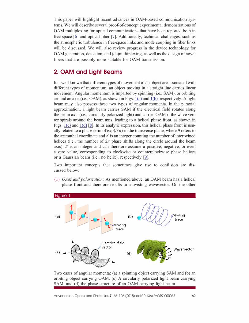
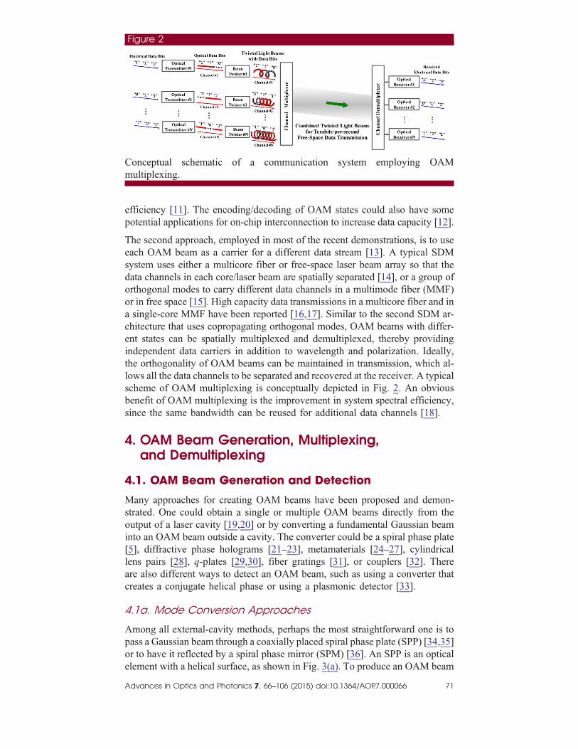
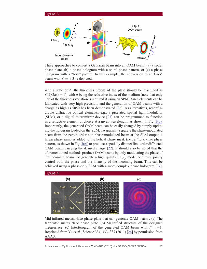
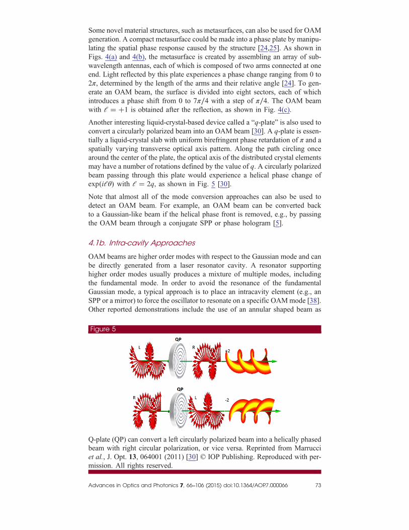
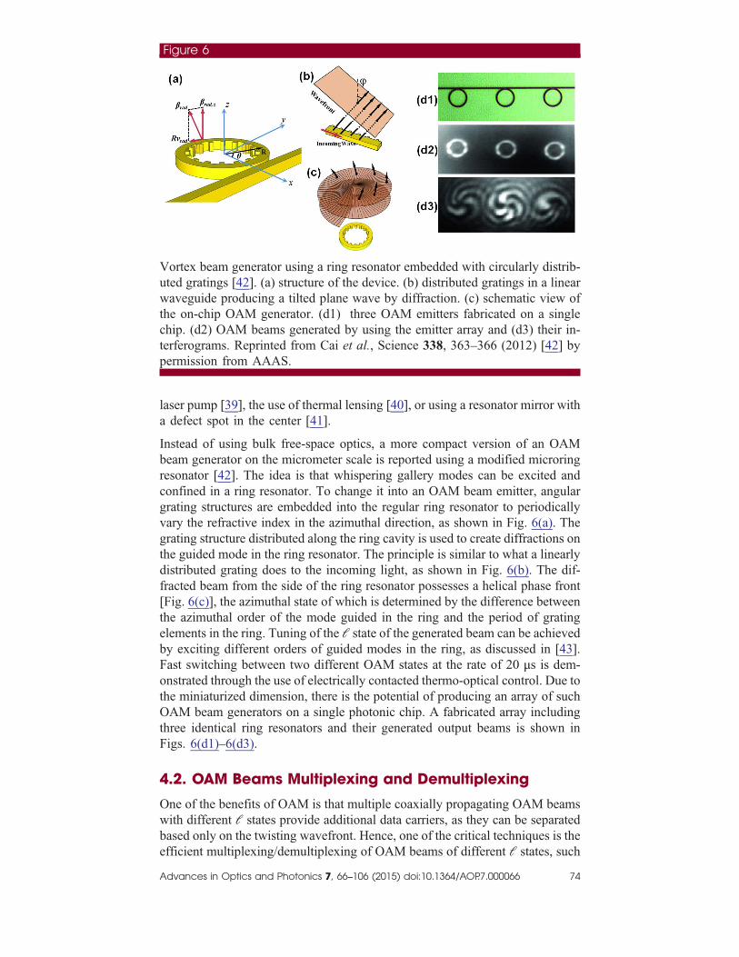
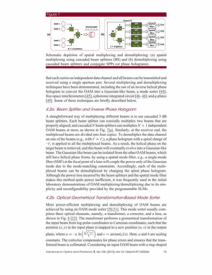
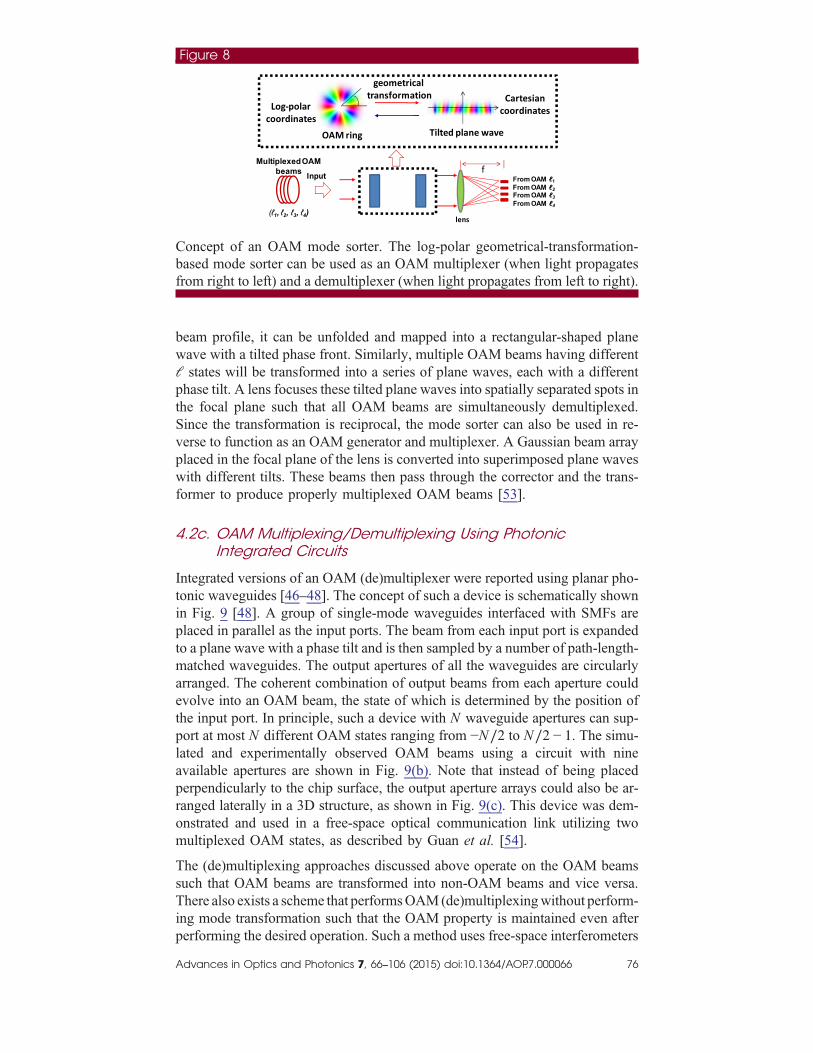
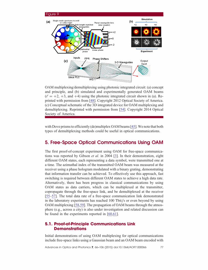
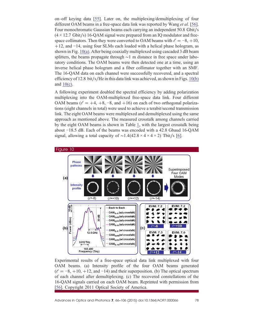
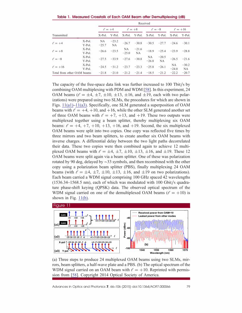
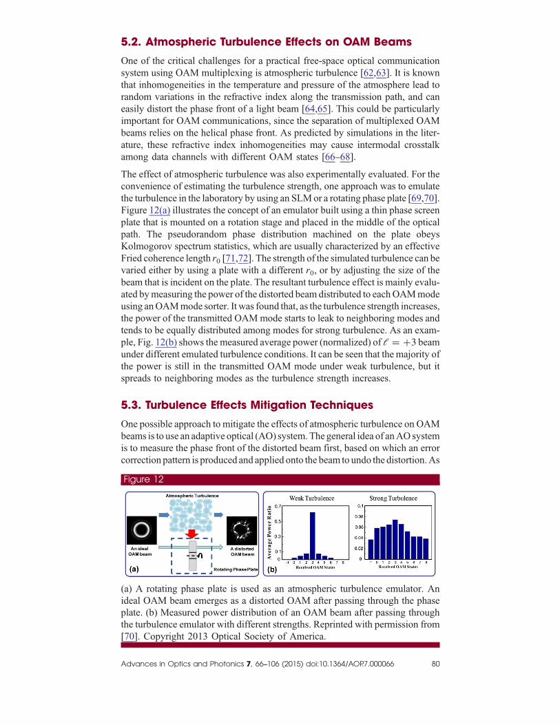
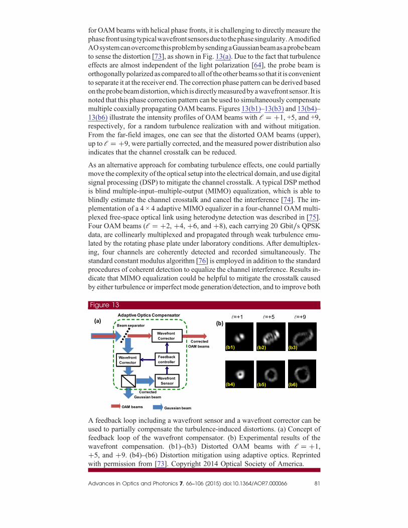
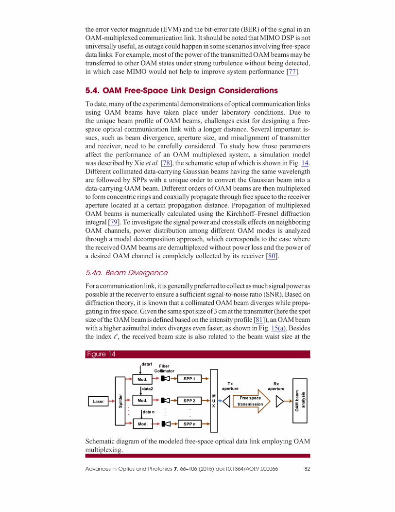
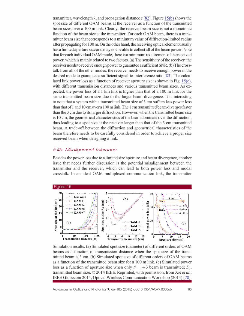
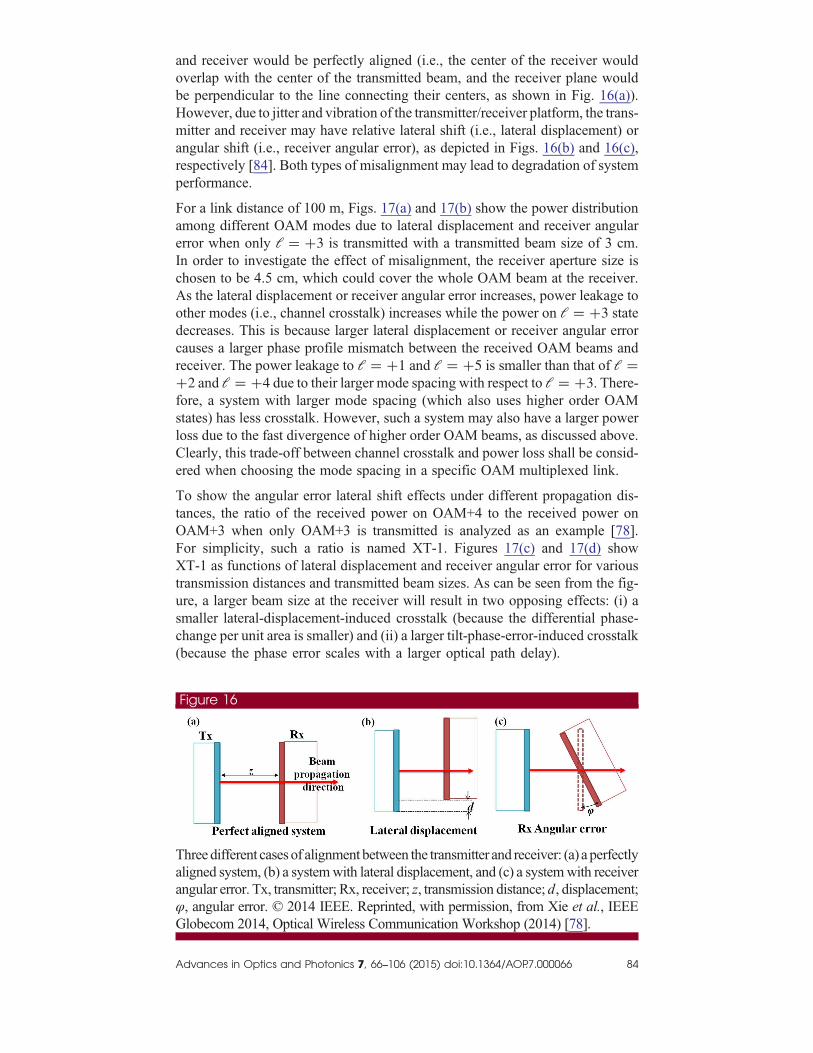
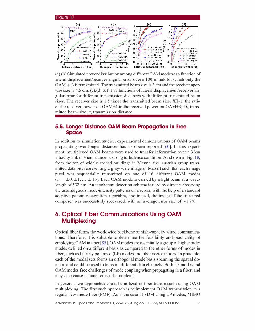
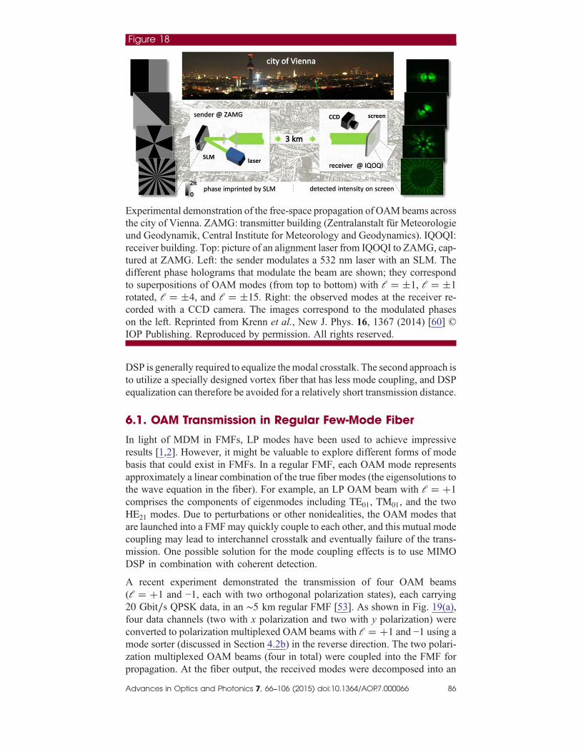
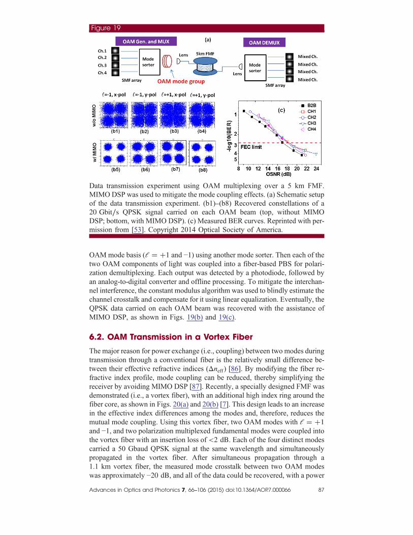
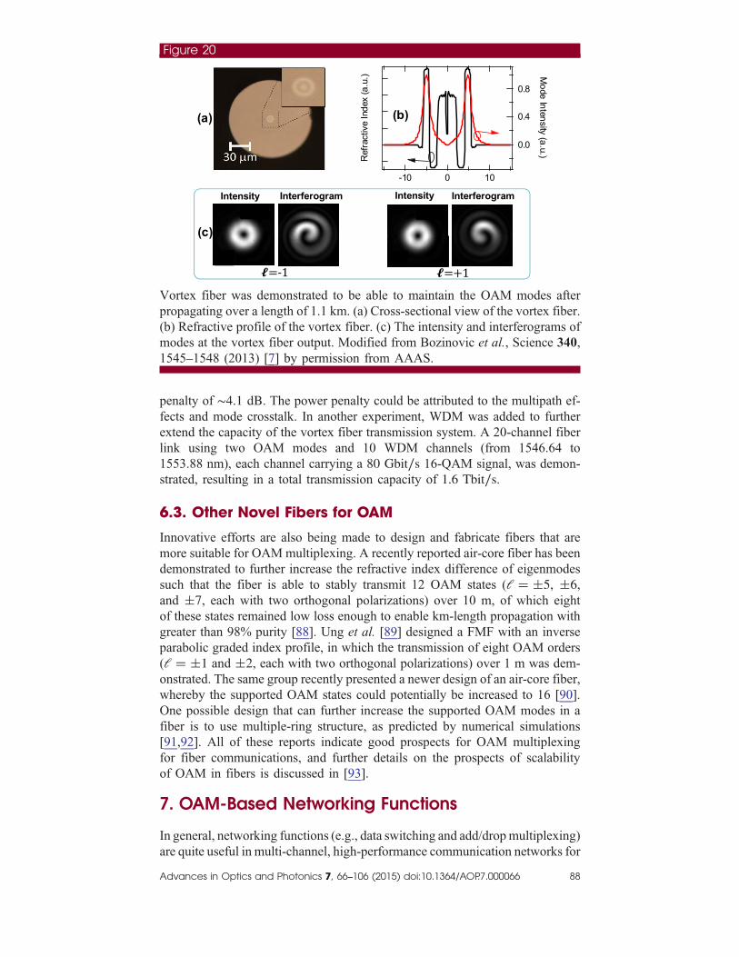
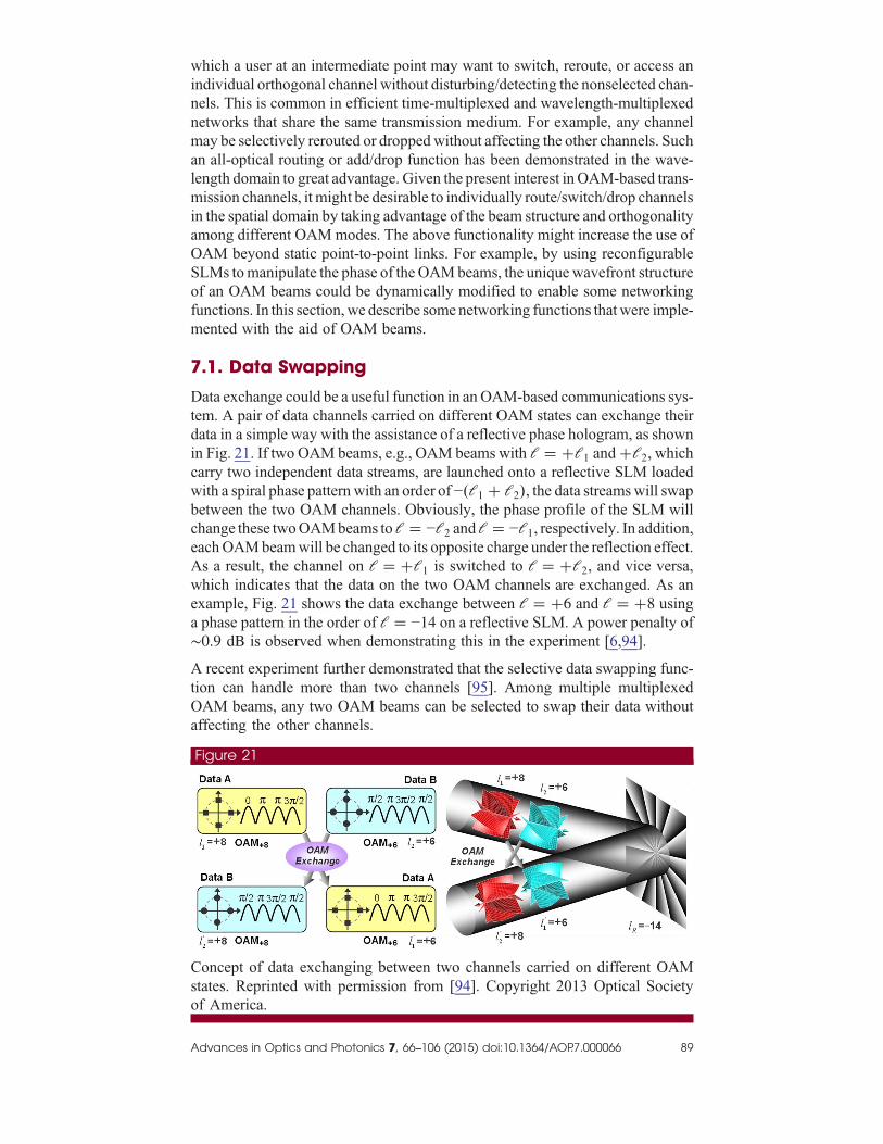
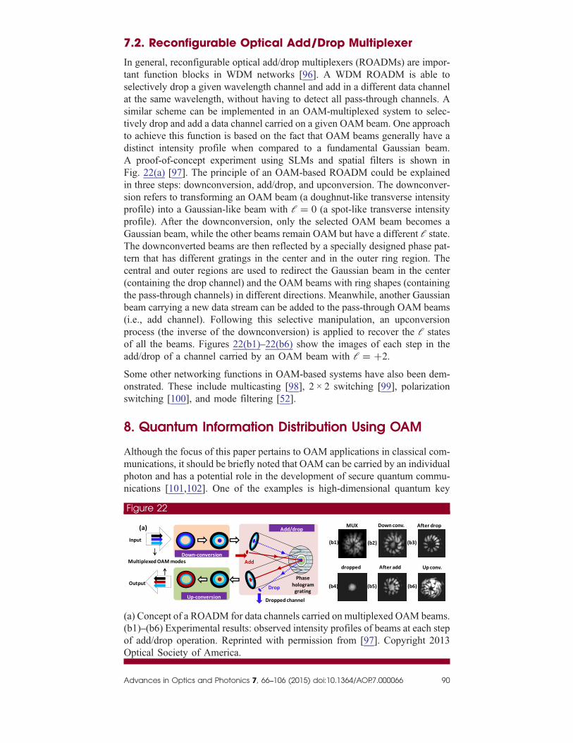
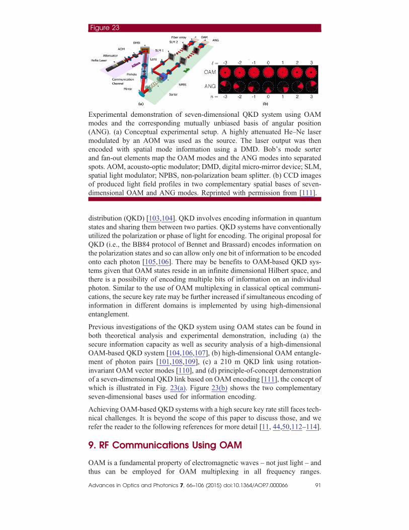
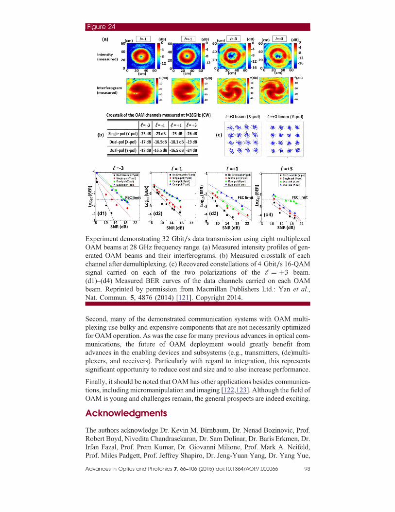
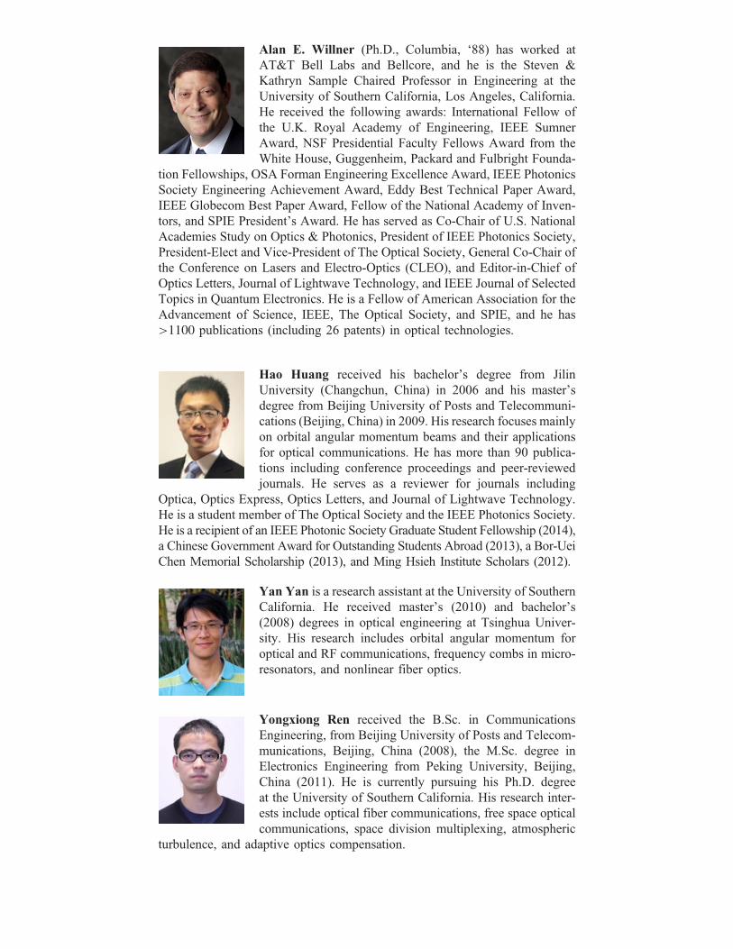
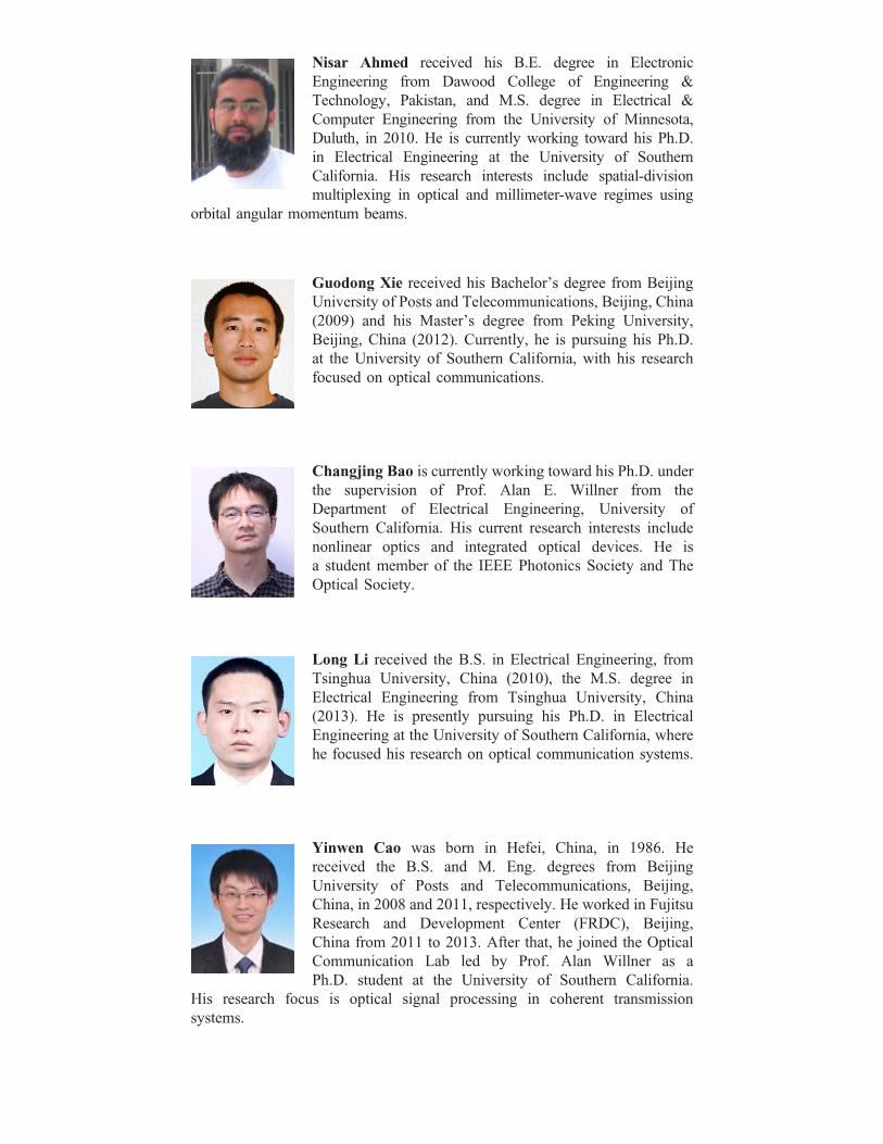
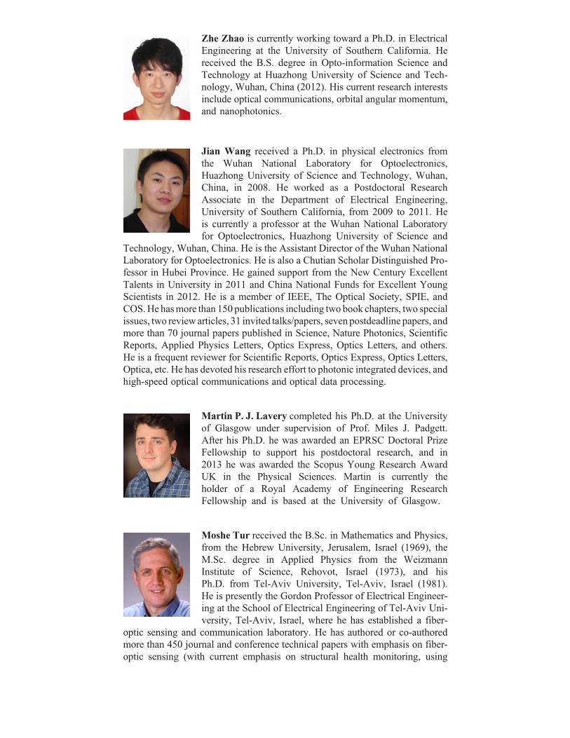
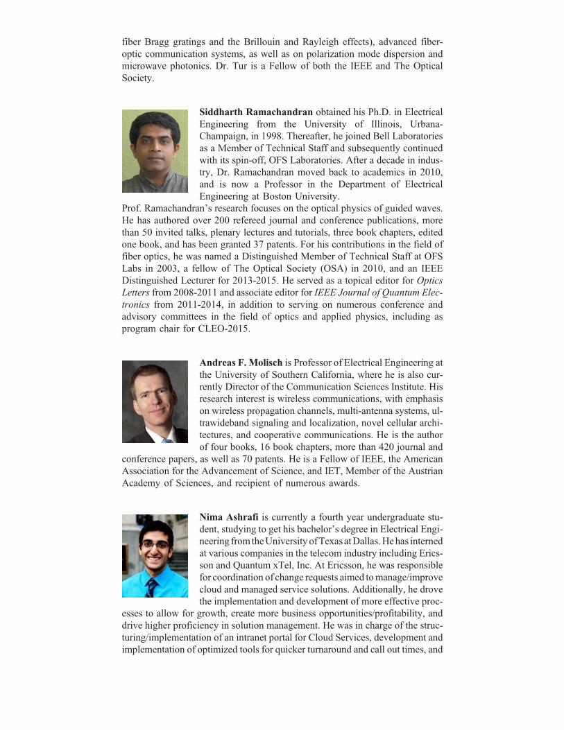


![Optical Communications [OC]](https://static.documents.pub/doc/80x56/577d1fe11a28ab4e1e918737/optical-communications-oc.jpg)

