Page 1
P
hoto
ele
ctric
Op
tical Data C
oup
lersPhotoelectric Sensors
711Singapore:[email protected]
USA:[email protected]
Germany:[email protected]
Pepperl+FuchsGroupwww.pepperl-fuchs.com
Subjecttomodificationswithoutnotice CopyrightPepperl+Fuchs
OpticalDataCouplers• Wireless data transfer over long
distances
• Replaces slip rings and drag cables that are susceptible to noise and inflexibility
• Parallel and serial data transfer
See page 723-726 for Optical Data Coupler dimensions and accessories.
DAD15-8P See pages 713-714
Features:• Largeoperatingangleandsensitivity
adjustmentallowforeasyalignment• LEDdisplayofinputandoutputstatus
Operating Ranges:1.5m,2.5m
Data Transfer Method:Parallel(8discreteinputs, 8PNPtransistoroutputs)
DAD30 Series See pages 715-717
Features:• Compactmetalhousing• Visibleandinfraredlightsources• Wideoperatingangleversion
Operating Ranges:15m,30m,100m
Data Transfer Method:Serial(RS-232,RS-422, CurrentLoop20mA)
LS230-DA SeriesSee pages 718-720
Features:• EasysetupwithintegratedalignmentLEDandsightglass• LEDbardisplayforsignalstrength• Heatedversionallowsoperationat-31ºF(-35ºC)
Operating Ranges:180m,230m
Data Transfer Method:Serial(RS-232,RS-422, CurrentLoop20mA)
LS610-DA-P Series See pages 721-723
Features:• LEDbardisplayofsignalstrength• Lowtemperatureversionratedto-22ºF(-30ºC)• INTERBUSversionsalsoavailable
Operating Ranges:120m,240m
Data Transfer Method:PROFIBUScompatible
Courtesy of Steven Engineering, Inc.-230 Ryan Way, South San Francisco, CA 94080-6370-Main Office: (650) 588-9200-Outside Local Area: (800) 258-9200-www.stevenengineering.com
Page 2
P
hoto
ele
ctr
ic
Op
tica
l Dat
a C
oup
lers
Photoelectric Sensors
712 Singapore:[email protected]
USA:[email protected]
Germany:[email protected]
Pepperl+FuchsGroupwww.pepperl-fuchs.com
Subjecttomodificationswithoutnotice CopyrightPepperl+Fuchs
Overview
IntroductionPepperl+Fuchsopticaldatacouplersprovidewirelesstransferofdatacommunicationthroughamodulatedinfraredlightbeam.UnlikeRF-basedcommunication,themodulatedsignalisimmunetonoiseinterference.Datacouplersareusedasaset:onetotransmitthedataandonetoreceive.Theyarecommonlyusedinoverheadmonorailsystems,mobiletransportunits,automatedguidedvehicles,andmaterialtransferstations.Datacouplersreplaceslipringsanddragcablesthataresusceptibletonoiseandhavelimitedflexibility.Theyhaveahightoleranceformisalignmentthatfrequentlyoccursinapplicationswithmovingequipment
Modulation TechniquePepperl+Fuchsusesfrequencyshiftkeying(FSK)tomodulatetheinfraredlightusedtotransferinformationbetweenthedatacouplers.FSKcanbethoughtofasdigitalmodulation.Thetransmittedsignalisshiftedbetweentwofrequenciesthatcorrespondtoeitherlogicbits0or1.Narrowbandfiltering,usedonthereceiversidetoconvertthedatabacktologic,preventsextraneoussignalsfromcorruptingthetransmitteddata.Thedatatransmissionisunaffectedbysignallevelvariation.
Output InterfacesPepperl+Fuchsoffersbothserialandparalleloutputinterfacesforthedatacouplers.Paralleldatacouplershaveeightdiscreteinputandeightoutputsignals,whereasserialdatacouplersrequireonlytwosignalsforcommunication.Sinceserialdatacouplerstransferdataonebitatatime,theyareslowerthantheparalleldatacouplers.Becauseoftheirspeed,paralleldatacouplersarepreferredforcommunicationsbetweenshortdistancesbutincreasedcostandlinelossesmakethemlesspracticalfordatatransmissionoverlongerdistances.
Note: All optical data coupler model numbers shown are single pieces, not pairs.
Applications
CleaningSolvents
PLCMain
Controller
Optical DataCouplers
Inasteelmillscrapyard,opticaldatacouplersprovidewirelessinformationexchangebetweenacraneoperator’stouchscreenandacentralcontroller.UnlikeapreviouslyinstalledRFsystem,theopticaldatacoupler’soperationwasunaffectedbysignalsfrommobilecommunicationdevices.
Informationexchangeforautomatedguidedvehicles
Anoverheadmonorailsystemisusedto“dip”(forthepurposeofcleaning)metal
machineparts.Thevatofcleaningsolventusedisdeterminedbythetypeofpartbeing
immersed.Opticaldatacouplerstransferserialinformationnecessaryforaremotemain
controllertoidentifytheproducts,regulatetimingfunctions,governmotorcontrol,etc.
Courtesy of Steven Engineering, Inc.-230 Ryan Way, South San Francisco, CA 94080-6370-Main Office: (650) 588-9200-Outside Local Area: (800) 258-9200-www.stevenengineering.com
Page 3
P
hoto
ele
ctric
Op
tical Data C
oup
lersPhotoelectric Sensors
713Singapore:[email protected]
USA:[email protected]
Germany:[email protected]
Pepperl+FuchsGroupwww.pepperl-fuchs.com
Subjecttomodificationswithoutnotice CopyrightPepperl+Fuchs
SpecificationsTRANSMITTER/RECEIVER SEPARATION 0-1.5 m 0-2.5 m
SENSITIVITY ADJUSTMENT Yes Yes
MODEL NUMBER(S) DAD15-8P DAD15-8P/35
COMMUNICATION INTERFACE 8-bit bidirectional parallel output
8-bit bidirectional parallel output
OUTPUT: Transistor, Normally Open
(8) PNP (8) PNP
— —
LOAD CURRENT 200 mA max. (per channel) 800 mA total
200 mA max. (per channel) 800 mA total
SHORT CIRCUIT AND OVERLOAD PROTECTION Yes Yes
REVERSE POLARITY PROTECTION Yes Yes
DATA RATE 225 bits/sec 225 bits/sec
TRANSMISSION TIME ≤ 35 ms ≤ 35 ms
INPUT HIGH 8-60 VDC 8-60 VDC
INPUT LOW 0-4 VDC or unwired 0-4 VDC or unwired
MODULATION TYPE PPM PPM
SUPPLY VOLTAGE 10-60 VDC 10-60 VDC
LED(s) Yes (18)* Yes (18)*
CURRENT CONSUMPTION ≤ 40 mA ≤ 40 mA
STANDARDS EN 60947-5-2 EN 60947-5-2
PROTECTION (IEC) IP67 IP67
LIGHT SPOT DIAMETER ≈ 1 m at a range of 1.5 m ≈ 500 mm at a range of 1.5 m
LIGHT BEAM ANGLE ± 20º ± 8º
LIGHT SOURCE Infrared LED Infrared LED
AMBIENT LIGHT RESISTANCE ≤ 5,000 lux ≤ 5,000 lux
TEMPERATURE RANGE
WORKING -22 ºF to +140 ºF -22 ºF to +140 ºF
STORAGE -22 ºF to +167 ºF -22 ºF to +167 ºF
HOUSING MATERIAL Terluran Terluran
LENS Glass Glass
WEIGHT 6.0 oz 6.0 oz
APPROVALS
ELECTRICAL CONNECTION Terminal
housingTerminal housing
ADDITIONAL DATA See pages 723-726
*See DAD15-8P Operation for LED functions.
DAD15-8POpticalDataCouplers
OperatingCharacteristics
1
10
100
3
0 1 32 4x DistanceX[m]
Exc
ess
Gai
n
Excess Gain vs. Sensing Range DAD15-8P
0
100
200
300
400
500
600
0 1 32 4x
y
DistanceX[m]
Offs
etY
[mm
]
DAD15-8PMovement Characteristics
0 1 32 54x DistanceX[m]
1
10
100
3
Exc
ess
Gai
n
Excess Gain vs. Sensing Range DAD15-8P/35
0 1 32 54x
y
DistanceX[m]
0
100
200
300
400
500
600
Offs
etY
[mm
]
DAD15-8P/35Movement Characteristics
StockeditemTypicaldelivery4weeksorlessConsultfactoryforallothermodels
Courtesy of Steven Engineering, Inc.-230 Ryan Way, South San Francisco, CA 94080-6370-Main Office: (650) 588-9200-Outside Local Area: (800) 258-9200-www.stevenengineering.com
Page 4
P
hoto
ele
ctr
ic
Op
tica
l Dat
a C
oup
lers
Photoelectric Sensors
714 Singapore:[email protected]
USA:[email protected]
Germany:[email protected]
Pepperl+FuchsGroupwww.pepperl-fuchs.com
Subjecttomodificationswithoutnotice CopyrightPepperl+Fuchs
DAD15-8POpticalDataCouplers
WiringDiagrams
DC
TerminalConnection
1
2
3
4
5
6
7
9
10
8
11
12
14
21
22
23
24
15
16
17
19
20
18
(+)(–)
(–)
Enable inputMaster/slave inputD1 inD2 inD3 inD4 inD5 inD6 inD7 inD8 in
D1 out (PNP)D2 out (PNP)D3 out (PNP)D4 out (PNP)D5 out (PNP)D6 out (PNP)D7 out (PNP)D8 out (PNP)Signal strength (PNP)Sync output (PNP)
Load
Load
Load
Load
Load
Load
Load
Load
Load
Load
DAD15-8P OperationTheDAD15-8Pseriesallowseightdiscreteinputsandeightdiscreteoutputstobetransmittedbi-directionallybetweentwoDAD15couplersviaaninfraredsignal.Fortransmission,twounitsarerequiredinwhichoneunitisthedesignatedMasterandtheotherunitisthedesignatedSlave.TheparallelbinarysignalsattheinputsD1throughD8areconvertedandtransmittedseriallyasan8-bitstringtothecoupleractingasareceiver.Inthereceiver,thestringisconvertedintoparalleldataagainandappliedtotheoutputsD1throughD8.PPM(PulsePositionModulation)isusedfordatatransmission.
Theentirecycle,inwhichbothofthe8-bitwordsaretransferredbi-directionally,oneaftertheotherandmultiplexed,lasts35ms.Thiscorrespondstoatransferrateof350Baud.Thelastdatareceivedissavedandisaccessibleattheoutputuntilthenextchangesaremade.
Status Indicator LEDs
TheLEDsontheunitindicatethestatusofthedevice.EightgreenLEDsindicatethestatesofinputs,andeightredLEDsindicatethestatesofoutputsD1throughD8.Inbothcases,whentheLEDison,theinputoroutputisactive.AnothergreenLED(Power-ON)indicatesifthedeviceisconnectedtoasupplyvoltage.TheremainingyellowLED(RxD)indicatesifthedeviceisreceivingdatawithanexcessgainofatleastone,whichissufficientfordatatransfer.TheeightgreeninputLEDsandeightredoutputLEDsarelocatedintwoseparate
rows,andthepowerLEDandsignalstrengthLEDarelocatedbetweenthesetworows(seeFigure1).
Inputs and OutputsAcceptableswitchinputstotheDAD15-8Pincludedrycontactsandopencollectortransistors,suchastransistoroutputsofsensors.TheoutputsoftheDAD15-8ParePNPtransistoroutputs.
TheSYNC-output,alsoaPNPoutput,canbeusedasastartsignaltomultiplexseveralmasters.Itindicatestheendofthecompletetransmissionandreceivingcycle.Withthefallingedgeofthissignal,theoutputdataisvalidandnewinputcanberead.ThisoutputcanbeusedtolaunchanotherMasterviatheEnableinput,whichallowsuptofourMasterstobeinterconnected.TheunitsthenmustbeaddressedviatheA1andA2DIPswitchesbelow,andtheslavecorrespondingtoitsrespectivemastershouldhavethesameaddress.Forexample,theSYNCoutputfromthefirstmaster(withaddressA1=0,A2=0)wouldbeconnectedtotheENABLEinputofthesecondmaster(withaddressA1=0,A2=1).
Thesignalstrengthoutput(aPNPoutput)isactivewhenthereissufficientexcessgain(i.e.,thesignalstrengthisacceptable).
TheEnableInputofaMastermustbeconnectedtoV+inordertooperatetheunit.ThetransmitterisdeactivatediftheEnableinputisconnectedtoV-ordisconnected.TheEnableInputofaSlaveisnotused.
TheMaster/SlaveinputdeterminesifadeviceisdesignatedasaMasteroraSlave.Fortransmission,twounitsarerequiredinwhichoneunitisthedesignatedMaster(Master/SlaveinputON)andtheotherunitisthedesignatedSlave(Master/SlaveinputOFF).
Controls for DAD15-8PTheDAD15-8Phasseveraladditionalcontrolsforoperation,includingapotentiometerlocatedonthesideofthehousing,andthreeDIPswitcheslocatedinsidethehousing.
Thepotentiometercontrolsthedistancetheinfraredbeamtravels.Thisadjustmentishelpfulineliminatingcrosstalkbetweendatacouplerscausedby“stray”infraredsignals.(Inmultipleunitapplications,crosstalkmayoccurduetothewideoffsetangleofthetransmissionbeam.)
DIPswitchfunctionsaredescribedbelow:
A1:determinestheaddressofadatacouplerpair.Amaster/slavepairmustbesettothesameaddressinordertoallowdatatransfer.
A2:determinestheaddressofadatacouplerpair.Amaster/slavepairmustbesettothesameaddressinordertoallowdatatransfer.
A3:notused.
A4:determineswhathappensifthelightbeambetweenthetwohalvesofthedatacouplerisbroken.IftheswitchisOFF,thenthedataoutputsareturnedoffintheeventofabeamobstruction.IftheswitchisON,thenthemostrecentlyreceiveddataisheldintheoutputsintheeventofabeamobstruction.
GreenLED:Power
Receivers Transmitters
1 8
1 8
GreenLEDs:Datainputs
RedLEDs:Dataoutputs
YellowLED:Signalstrength(excessgain=1)
Sensitivityadjustment(behindthesealingscrew)
transmit receive
transmitreceive
transmit receive
transmit receive
Master1
SynchMaster1
Slave1
SynchSlave1(onlywhenreceiving)
SynchMaster1inEnableMaster2Master2
SynchMaster2
3ms 3ms 35ms
hl
hl
hl
0.5ms
0.3ms
Figure 1
Courtesy of Steven Engineering, Inc.-230 Ryan Way, South San Francisco, CA 94080-6370-Main Office: (650) 588-9200-Outside Local Area: (800) 258-9200-www.stevenengineering.com
Page 5
P
hoto
ele
ctric
Op
tical Data C
oup
lersPhotoelectric Sensors
715Singapore:[email protected]
USA:[email protected]
Germany:[email protected]
Pepperl+FuchsGroupwww.pepperl-fuchs.com
Subjecttomodificationswithoutnotice CopyrightPepperl+Fuchs
SpecificationsTRANSMITTER/RECEIVER SEPARATION 0-15 m 0-30 m 0-30 m
MODEL NUMBER(S) DAD30-W DAD30 DAD30-RT
COMMUNICATION INTERFACES RS-232, RS-422, CL 20 mA active/passive
RS-232, RS-422, CL 20 mA active/passive
RS-232, RS-422, CL 20 mA active/passive
REVERSE POLARITY PROTECTION Yes (33 VDC max.) Yes (33 VDC max.) Yes (33 VDC max.)
TRANSMISSION RATE 0-19.2 kBits/s 0-19.2 kBits/s 0-19.2 kBits/s
TRANSMISSION TIME ≤ 40 µs ≤ 40 µs ≤ 40 µs
MODULATION TYPE FSK FSK FSK
CARRIER FREQUENCY F1 = 83 kHz, F2 = 118 kHz F1 = 83 kHz, F2 = 118 kHz F1 = 83 kHz, F2 = 118 kHz
SUPPLY VOLTAGE 18-30 VDC 18-30 VDC 18-30 VDC
LED(s) Yes (2)* Yes (2)* Yes (2)*
CURRENT CONSUMPTION ≤ 200 mA ≤ 200 mA ≤ 200 mA
STANDARDS EN 60947-5-2 EN 60947-5-2 EN 60947-5-2
PROTECTION (IEC) IP65 IP65 IP65
LIGHT SPOT DIAMETER 4.2 m at a range of 15 m 500 mm at a range of 30 m 500 mm at a range of 30 m
LIGHT BEAM ANGLE 16º transmitter/16º receiver 1º transmitter/5º receiver 1º transmitter/5º receiver
LIGHT SOURCE Infrared LED Infrared LED Visible red LED
AMBIENT LIGHT RESISTANCE ≤ 30,000 lux ≤ 30,000 lux ≤ 30,000 lux
TEMPERATURE RANGE
WORKING -4 ºF to +140 ºF -4 ºF to +140 ºF -4 ºF to +140 ºF
STORAGE -4 ºF to +167 ºF -4 ºF to +167 ºF -4 ºF to +167 ºF
HOUSING MATERIAL Aluminum Aluminum Aluminum
LENS Glass Plastic Plastic
WEIGHT 17.6 oz 17.6 oz 17.6 oz
APPROVALS
ELECTRICAL CONNECTION
25-pin male D-sub
connector
25-pin male D-sub
connector
25-pin male D-sub
connector
ADDITIONAL DATA See pages 723-726
*See dimensional drawings for LED functions.
DAD30OpticalDataCouplers
OperatingCharacteristics
0 10 20 30 40 50x DistanceX[m]
1
10
100
1000
3
Exc
ess
Gai
n
Excess Gain vs. Sensing Range DAD30
050
100
150200250300350400450
0 10 155 20 25 30 35x
y
DistanceX[m]
Offs
etY
[mm
]
DAD30Movement Characteristics
StockeditemTypicaldelivery4weeksorlessConsultfactoryforallothermodels
Courtesy of Steven Engineering, Inc.-230 Ryan Way, South San Francisco, CA 94080-6370-Main Office: (650) 588-9200-Outside Local Area: (800) 258-9200-www.stevenengineering.com
Page 6
P
hoto
ele
ctr
ic
Op
tica
l Dat
a C
oup
lers
Photoelectric Sensors
716 Singapore:[email protected]
USA:[email protected]
Germany:[email protected]
Pepperl+FuchsGroupwww.pepperl-fuchs.com
Subjecttomodificationswithoutnotice CopyrightPepperl+Fuchs
SpecificationsTRANSMITTER/RECEIVER SEPARATION 0-100m 0-100m
MODEL NUMBER(S) DAD30/35 DAD30-RT/35
COMMUNICATION INTERFACES RS-232, RS-422, CL 20 mA active/passive
RS-232, RS-422, CL 20 mA active/passive
REVERSE POLARITY PROTECTION Yes (33 VDC max.) Yes (33 VDC max.)
TRANSMISSION RATE 0-19.2 kBits/s 0-19.2 kBits/s
TRANSMISSION TIME ≤ 40 µs ≤ 40 µs
MODULATION TYPE FSK FSK
CARRIER FREQUENCY F1 = 83 kHz, F2 = 118 kHz F1 = 83 kHz, F2 = 118 kHz
SUPPLY VOLTAGE 18-30 VDC 18-30 VDC
LED(s) Yes (2)* Yes (2)*
CURRENT CONSUMPTION ≤ 200 mA ≤ 200 mA
STANDARDS EN 60947-5-2 EN 60947-5-2
PROTECTION (IEC) IP65 IP65
LIGHT SPOT DIAMETER 1.8 m at a range of 100 m 1.8 m at a range of 100 m
LIGHT BEAM ANGLE 1º transmitter/5º receiver 1º transmitter/5º receiver
LIGHT SOURCE Infrared LED Visible red LED
AMBIENT LIGHT RESISTANCE ≤ 30,000 lux ≤ 30,000 lux
TEMPERATURE RANGE
WORKING -4 ºF to +140 ºF -4 ºF to +140 ºF
STORAGE -4 ºF to +167 ºF -4 ºF to +167 ºF
HOUSING MATERIAL Aluminum Aluminum
LENS Glass Glass
WEIGHT 17.6 oz 17.6 oz
APPROVALS
ELECTRICAL CONNECTION
25-pin male D-sub
connector
25-pin male D-sub
connector
ADDITIONAL DATA See pages 723-726
*See dimensional drawings for LED functions.
DAD30OpticalDataCouplers
WiringDiagrams
DC
25-pinD-SubConnector
2 RX232
3 TX232
6 Alarm 1
7
9
10 RX-DIS
11
13 RX-DIS/TTL
14 RX-P
12 Alarm 2
15 RX-N
16 TX-P17 TX-N
18 CL-IN+
19 CL-IN-
21 CL-OUT-
22 TX-DIS
25 CL-OUT+
(+)
(–)Analog signal strength output*Data blanking input
RS-422 data switch input
Transmitter deactivation
Signal strength output 1 (PNP)
Signal strength output 2 (PNP)
RS-232 outputRS-232 input
Current loop input
Current loop inputCurrent loop output
Current loop output
RS-422 (B-input)RS-422 (A-input)RS-422 (B-output)RS-422 (A-output)
Load
Load
Load
Male Receptacle End View
1
25
*PIN 9: AnalogOutput+1.8VDCto+5.8VDC(10mAmax)
Note: Wiringdiagramsshowquick disconnectpinnumbers.
Opticaldatacoupler,passive
Active/Passive Modefor 20mA CL Interface
Controller
Active Passive
18
18
19
21
25
57+
+
+
+ S8
20mA
20mA
Figure 1
StockeditemTypicaldelivery4weeksorlessConsultfactoryforallothermodels
Courtesy of Steven Engineering, Inc.-230 Ryan Way, South San Francisco, CA 94080-6370-Main Office: (650) 588-9200-Outside Local Area: (800) 258-9200-www.stevenengineering.com
Page 7
P
hoto
ele
ctric
Op
tical Data C
oup
lersPhotoelectric Sensors
717Singapore:[email protected]
USA:[email protected]
Germany:[email protected]
Pepperl+FuchsGroupwww.pepperl-fuchs.com
Subjecttomodificationswithoutnotice CopyrightPepperl+Fuchs
DAD30OpticalDataCouplers
DAD30 OperationTheDAD30seriesallowsfull-duplexserialdatatransferfortransmissionratesupto19.2kBaudandrangesupto100meters.Iftwofull-duplexroutesaretobeusedinparallel,onepairshouldhaveaninfraredlightsourceandtheotherpairshouldhaveavisibleredlightsource.Theserialdataistransferredfromthetransmittertothereceiverwithoutusinganintermediateprotocol.
Status Indicator LEDsTheDAD30serieshasatwo-colorLED.WhentheLEDisred,thedeviceisreceivingdataatanexcessgainofatleastone.ThegreenLEDindicatesitisreceivingdataatanexcessgainofatleastthree.Thehighertheexcessgainofthedatatransmission,thestrongerthesignal.AnadditionalredLEDindicatesiftheDataBlankingInput(describedbelow)isactive.
Inputs and Outputs• SignalStrengthOutput#1(Pin6)PNPoutput,short-
circuitproof,100mA,30VDC.Whenactive,thisoutputindicatesthereissufficientexcessgaintoallowdatatransfer.
• AnalogSignalStrengthOutput(Pin9)+1.8VDCto+5.8VDC(10mAmaximumcurrent)whichindicatestheexcessgainforalignmentpurposes.At2.5VDC,anexcessgainofatleastoneisachieved,andat4.2VDC,anexcessgainofatleastthreeisachieved.
• DataBlankingInput(Pin10)Applying4-30VDCtothisinputcausesallreceiveroutputstobeturnedoffontheoppositecoupler.Thisdoesnotdeactivatethecouplers,butrathersimulatesalogic‘0’ontheoppositeside.
• SignalStrengthOutput#2(Pin12)PNPoutput,short-circuitproof,100mA,30VDC.Whenactive,thisoutputindicatesthereisthreetimessufficientexcessgaintoallowdatatransfer.
• RS-422DataSwitchInput(Pin13)AttachingV-orgroundtothisinputswitchesofftheRS-422modelinedriver(pins16and17),allowingonlydatatobetransmittedbyRS-422butnottobereceived.Thisfunctionisneededifseveraldatatransmissionsusethesamedataline(multidrop).Thenormalmode(inwhichPin13isnotconnected)allowsaninternalpull-upresistortoapply5VDCtothispinandactivatethelinedriverforRS-422.
• TransmitterDeactivation(Pin22)ApplyingV+deactivatesthetransmitter.
AllotheroutputsrelatedirectlytooneofthethreeinterfacetypesthatcanbeusedfortheDAD30series:RS-232,RS-422,andCL20mA.
Whenthelightbeambetweenthetransmitterandreceiverisbroken,thereceiversidegoesintopausestatus.Thisstatusislogichighfornon-inverteddatalines.
Controls for DAD30TheDAD30serieshaseightDIPswitches,whicharelocatedinsidethehousing.Theseswitchesshouldbesetasfollows:
• S1:CarrierFrequencySetting.Toallowonefullduplexroute(twocouplers),thetransmitterandreceivermustbesetatdifferentfrequencies.Thatis,onedevicemustbesetatfrequencyF1andtheotherdeviceatF2.
ON =transmitterF1,receiverF2 OFF =transmitterF2,receiverF1
• S2:InversionoftheTransmitterSignal.
ON =transmitterinputsignalisinverted OFF =transmitterinputsignalisnotinverted
• S3:InversionoftheReceiverSignal.
ON =receiveroutputsignalisinverted OFF =receiveroutputsignalisinverted
Caution:OnlyoneofswitchesS4,S5,andS6shouldbeturnedon.
• S4:20mACL(CurrentLoop)Interface.
ON =20mACLinterfaceactive OFF =20mACLinterfacenotactive
TheLogic‘0’isdefinedas0mA,andlogic‘1’isdefinedas20mA.The20mACLinterfacecreatesa20mAcurrentloopbetweenthedatacouplerandaserialdevice.Eachloopisrequiredtohaveacurrentsource,whetherthecurrentsourceisattheopticaldatacouplerendortheserialdeviceend.The20mACLinterfacecantransferdataovercablelengthsofupto3,280feet(1km).
• S5:RS422Interface
ON =RS422interfaceactive OFF =RS422interfacenotactive
Serialvoltageinterfacesuitablefortransmissiononupto1500metercablelength.Logic‘0’isdefinedas+2to+5VDC,andlogic‘1’isdefinedas–2to–5VDC.
• S6:RS232Interface
ON =RS232interfaceactive OFF =RS232interfacenotactive
Serialvoltageinterfacesuitableforup20metercablelength.Logic‘0’isdefinedas+3to+15VDC,andlogic‘1’isdefinedas–3to–15VDC.
• S7:Onlyusedfor20mACLinterface
ON =Inputinterfaceisactive OFF =Inputinterfaceispassive
• S8:Onlyusedfor20mACLinterface
ON =Outputinterfaceisactive OFF =Outputinterfaceispassive
Theactivemodeforthe20mACLinterfaceactivatesacurrentsourceintheDAD30unititself.Thepassivemodeforthe20mACLinterfaceindicatesthatacurrentsourcemustbeappliedexternallyandisnotactiveintheDAD30unit.PleaseseeFigure1onpreviouspage.
Courtesy of Steven Engineering, Inc.-230 Ryan Way, South San Francisco, CA 94080-6370-Main Office: (650) 588-9200-Outside Local Area: (800) 258-9200-www.stevenengineering.com
Page 8
P
hoto
ele
ctr
ic
Op
tica
l Dat
a C
oup
lers
Photoelectric Sensors
718 Singapore:[email protected]
USA:[email protected]
Germany:[email protected]
Pepperl+FuchsGroupwww.pepperl-fuchs.com
Subjecttomodificationswithoutnotice CopyrightPepperl+Fuchs
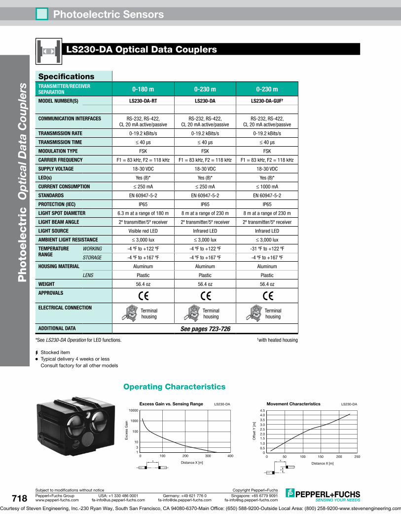
SpecificationsTRANSMITTER/RECEIVER SEPARATION 0-180 m 0-230 m 0-230 m
MODEL NUMBER(S) LS230-DA-RT LS230-DA LS230-DA-GUF†
COMMUNICATION INTERFACES RS-232, RS-422, CL 20 mA active/passive
RS-232, RS-422, CL 20 mA active/passive
RS-232, RS-422, CL 20 mA active/passive
TRANSMISSION RATE 0-19.2 kBits/s 0-19.2 kBits/s 0-19.2 kBits/s
TRANSMISSION TIME ≤ 40 µs ≤ 40 µs ≤ 40 µs
MODULATION TYPE FSK FSK FSK
CARRIER FREQUENCY F1 = 83 kHz, F2 = 118 kHz F1 = 83 kHz, F2 = 118 kHz F1 = 83 kHz, F2 = 118 kHz
SUPPLY VOLTAGE 18-30 VDC 18-30 VDC 18-30 VDC
LED(s) Yes (8)* Yes (8)* Yes (8)*
CURRENT CONSUMPTION ≤ 250 mA ≤ 250 mA ≤ 1000 mA
STANDARDS EN 60947-5-2 EN 60947-5-2 EN 60947-5-2
PROTECTION (IEC) IP65 IP65 IP65
LIGHT SPOT DIAMETER 6.3 m at a range of 180 m 8 m at a range of 230 m 8 m at a range of 230 m
LIGHT BEAM ANGLE 2º transmitter/5º receiver 2º transmitter/5º receiver 2º transmitter/5º receiver
LIGHT SOURCE Visible red LED Infrared LED Infrared LED
AMBIENT LIGHT RESISTANCE ≤ 3,000 lux ≤ 3,000 lux ≤ 3,000 lux
TEMPERATURE RANGE
WORKING -4 ºF to +122 ºF -4 ºF to +122 ºF -31 ºF to +122 ºF
STORAGE -4 ºF to +167 ºF -4 ºF to +167 ºF -4 ºF to +167 ºF
HOUSING MATERIAL Aluminum Aluminum Aluminum
LENS Plastic Plastic Plastic
WEIGHT 56.4 oz 56.4 oz 56.4 oz
APPROVALS
ELECTRICAL CONNECTION Terminal
housingTerminal housing
Terminal housing
ADDITIONAL DATA See pages 723-726
*See LS230-DA Operation for LED functions. †with heated housing
LS230-DAOpticalDataCouplers
OperatingCharacteristics
0 100 200 300 400x DistanceX[m]
1
10
100
1000
10000
3
Exc
ess
Gai
n
Excess Gain vs. Sensing Range LS230-DA
0 50 100 150 200 250x
y
DistanceX[m]
00.51.0
1.52.02.53.03.54.04.5
Offs
etY
[m]
LS230-DAMovement Characteristics
StockeditemTypicaldelivery4weeksorlessConsultfactoryforallothermodels
Courtesy of Steven Engineering, Inc.-230 Ryan Way, South San Francisco, CA 94080-6370-Main Office: (650) 588-9200-Outside Local Area: (800) 258-9200-www.stevenengineering.com
Page 9
P
hoto
ele
ctric
Op
tical Data C
oup
lersPhotoelectric Sensors
719Singapore:[email protected]
USA:[email protected]
Germany:[email protected]
Pepperl+FuchsGroupwww.pepperl-fuchs.com
Subjecttomodificationswithoutnotice CopyrightPepperl+Fuchs
LS230-DAOpticalDataCouplers
WiringDiagrams
DC
TerminalConnection
1 RX-P
2 RX-N
3 GNDI
4 TX-P
5 TX-N
6 GNDI
7 RX-DIS
9 TX232
10 CL-IN+
8 RX232
11 CL-IN-
12 CL-OUT+
14 TX-DIS
21
22
23
24
15
16
19
20 TX-DIS
(+)(+)(–)(–)
Signal strength output 2 (PNP)Signal strength output 1 (PNP)
Current loop outputCurrent loop inputCurrent loop inputRS-232 outputRS-232 inputReceiver deactivation input TTL
Transmitter deactivation input TTL
Analog signal strength output (to V-)Transmitter deactivation input
Data groundRS-422 (A-output)RS-422 (B-output)
RS-422 (B-input)RS-422 (A-input)
Data ground
13 CL-OUT- Current loop output
Load
Load
Load
Note: RS-232 inputs connect to transmitter of device, and RS-232 outputs connect to receiver of device.
LS230-DA OperationTheLS230-DAseriesallowsfull-duplexserialdatatransferfortransmissionratesupto19.2kBaudandrangesupto230meters.Iftwofull-duplexroutesaretobeusedinparallel,onepairshouldhaveaninfraredlightsourceandtheotherpairshouldhaveavisibleredlightsource.Theserialdataistransferredfromthetransmittertothereceiverwithoutusinganintermediateprotocol.
Status Indicator LEDsTheLS230-DAhaseightLEDsforoperationandalignmentindication(seefigureatright).ThelowerrowofLEDsclosesttothesightglassisaseriesofthreecolorLEDsusedforalignment.TheredLEDinthisrowindicatesanexcessgainofone,ortheminimumsignalstrengthtoallowdatatransfer.Toaidinalignment,thefouryellowLEDsnexttotheredoneindicateincreasingsignalstrength(i.e.,allfouryellowLEDsonindicatesastrongersignalthanjusttwoLEDsbeingon).ThegreenLEDalsoonthisrowindicatesanexcessgainofatleastthree.ThetwoLEDsontheupperrowindicateactivedataflow,withthegreenLEDindicatingdataistransmittedandtheyellowLEDindicatingdataisreceived.
AtelescopicsightglassonthetopoftheunitnexttotheLEDsandavisibleredLEDonthefrontofthehousingaidinalignment.Thevisibleredalignmentaidflashesaftertheunitispoweredandstopsafterthesignalstrengthhasincreasedtotheminimumrequiredvalue.TheflashingLEDandsightglassallowtheoppositedatacouplertobeeasilylocatedandalignedforthebestdatatransmission.
Inputs and Outputs• ReceiverDeactivationInputTTL-compatible(Terminal7)
ReceiverdeactivatedforRS-485outputwhen(symbolfor</=)0.5VDCisapplied.(Vo=5VDC,Ri=4.7kW)
• TransmitterDeactivationInputTTL-compatible(Terminal14)Transmitterdeactivatedwhen0-2VDCisapplied.(Vo=5VDC,Ri=4.7kW)
• SignalStrengthOutput#1(Terminal15)PNPoutput,short-circuitproof,100mA,30VDC.Whenactive,thisoutputindicatesthereissufficientexcessgaintoallowdatatransfer.
• SignalStrengthOutput#2(Terminal16)PNPoutput,short-circuitproof,100mA,30VDC.Whenactive,thisoutputindicatesthereisthreetimessufficientexcessgaintoallowdatatransfer.
• AnalogSignalStrengthOutput(Terminal19)+2.5VDCto+6VDC(10mAmaximumcurrent)whichindicatestheexcessgainforalignmentpurposes.At+3.5VDC,anexcessgainofatleastoneisachieved,andat+5.0VDC,anexcessgainofatleastthreeisachieved.
• TransmitterDeactivationInput(Terminal20)Transmitterdeactivatedwhen+4VDCto+30VDC(6mAmaximumcurrent)isapplied.
Whenthelightbeambetweenthetransmitterandreceiverisobstructed,thereceiversidegoesintopausestatus.Thisstatusislogichighfornon-inverteddatalines.
Controls for LS230-DATheLS230-DAserieshaseightDIPswitches,whicharelocatedinsidethehousing.Theseswitchesshouldbesetasfollows:
• S1:CarrierFrequencySetting.Toavoidmutualinterference,thetransmitterofonedeviceissetatF1carrierfrequency(whichsetsthereceiverinthesame
Green:Transmitterdataflow
Yellow:Receiverdataflow
Red:Signalstrength(excessgain=1)
Yellow(x4):Signalstrength
Sightglass
Green:Signalstrength(excessgain=3)
24
22
20
18
16
14
12
10
8
4
6
2
23
21
19
17
15
13
11
9
7
3
5
1
12
34
56
78
ON
OFF
Courtesy of Steven Engineering, Inc.-230 Ryan Way, South San Francisco, CA 94080-6370-Main Office: (650) 588-9200-Outside Local Area: (800) 258-9200-www.stevenengineering.com
Page 10
P
hoto
ele
ctr
ic
Op
tica
l Dat
a C
oup
lers
Photoelectric Sensors
720 Singapore:[email protected]
USA:[email protected]
Germany:[email protected]
Pepperl+FuchsGroupwww.pepperl-fuchs.com
Subjecttomodificationswithoutnotice CopyrightPepperl+Fuchs
LS230-DAOpticalDataCouplers
deviceatF2frequency)andthetransmitteroftheoppositeunitissetatF2frequency(whichsetsthereceiverinthesamedeviceatF1frequency).
ON =transmitterF1,receiverF2 OFF =transmitterF2,receiverF1
Caution:OnlyoneofswitchesS2,S3,andS4shouldbeturnedon.
• S2:20mACL(CurrentLoop)Interface.
ON =20mACLinterfaceactive OFF =20mACLinterfacenotactive
The20mACLinterfacecreatesa20mAcurrentloopbetweenthedatacouplerandaserialdevice.Eachloopisrequiredtohaveacurrentsource,whetherthecurrentsourceisattheopticaldatacouplerendortheserialdeviceend.TheLogic‘0’isdefinedas0mA,andlogic‘1’isdefinedas20mAforthe20mACLinterface,anditcantransferdataovercablelengthsofupto3,280feet(1km).
• S3:RS232Interface
ON =RS232interfaceactive OFF =RS232interfacenotactive
Serialvoltageinterfacesuitableforup65feet(20m)cablelength.Logic‘0’isdefinedas+3to+15VDC,andlogic‘1’isdefinedas–3to–15VDC,anditreferencesacommonground.
• S4:RS422Interface
ON =RS422interfaceactive OFF =RS422interfacenotactive
Serialvoltageinterfacesuitablefortransmissiononupto4,921feet(1.5km)cablelength.Logic‘0’isdefinedas+2to+5VDC,andlogic‘1’isdefinedas–2to–5VDC.
• S5:Inversionofthetransmittersignal.
ON =transmitterinputsignalisinverted OFF =transmitterinputsignalisnotinverted
• S6:Inversionofthereceiversignal.
ON =receiveroutputsignalisinverted OFF =receiveroutputsignalisnotinverted
• S7:Onlyusedfor20mACLinterface
ON =Inputinterfaceisactive OFF =Inputinterfaceispassive
• S8:Onlyusedfor20mACLinterface
ON =Outputinterfaceisactive OFF =Outputinterfaceispassive
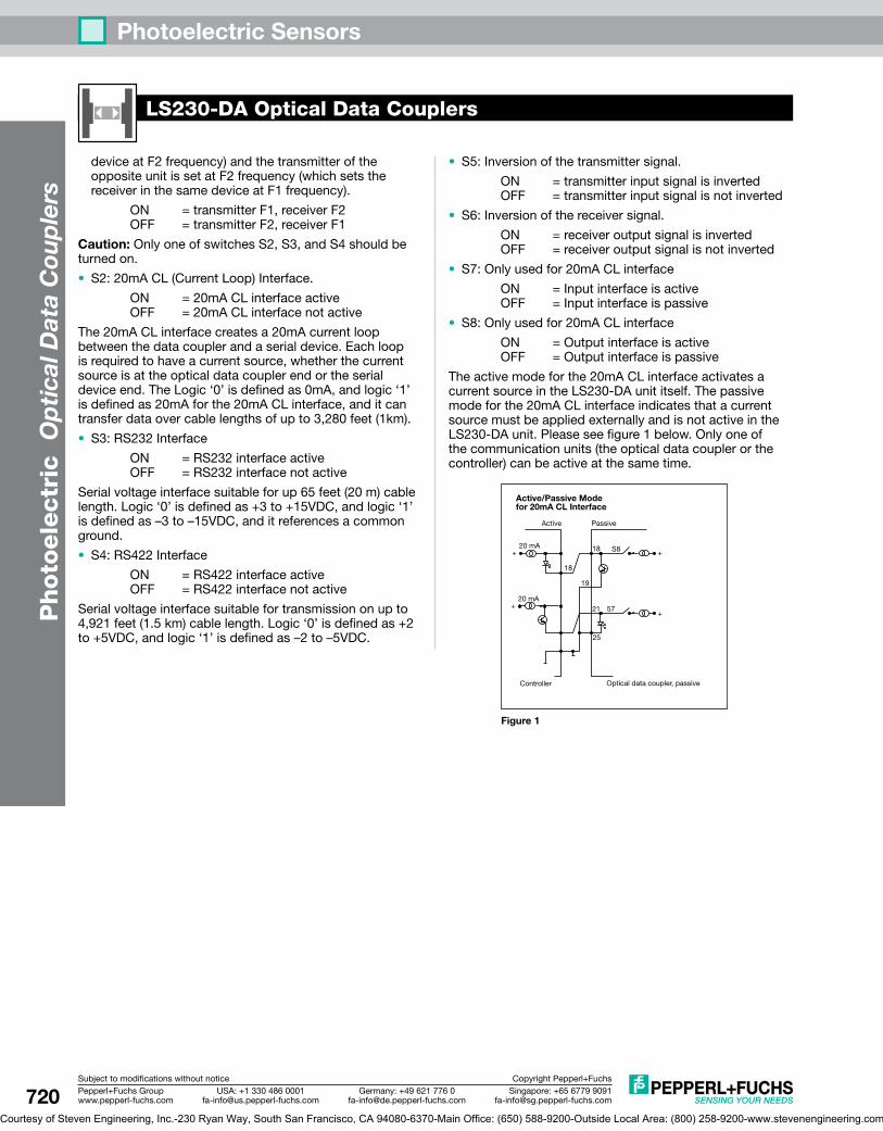
Theactivemodeforthe20mACLinterfaceactivatesacurrentsourceintheLS230-DAunititself.Thepassivemodeforthe20mACLinterfaceindicatesthatacurrentsourcemustbeappliedexternallyandisnotactiveintheLS230-DAunit.Pleaseseefigure1below.Onlyoneofthecommunicationunits(theopticaldatacouplerorthecontroller)canbeactiveatthesametime.
Opticaldatacoupler,passive
Active/Passive Modefor 20mA CL Interface
Controller
Active Passive
18
18
19
21
25
57+
+
+
+ S8
20mA
20mA
Figure 1
Courtesy of Steven Engineering, Inc.-230 Ryan Way, South San Francisco, CA 94080-6370-Main Office: (650) 588-9200-Outside Local Area: (800) 258-9200-www.stevenengineering.com
Page 11
P
hoto
ele
ctric
Op
tical Data C
oup
lersPhotoelectric Sensors
721Singapore:[email protected]
USA:[email protected]
Germany:[email protected]
Pepperl+FuchsGroupwww.pepperl-fuchs.com
Subjecttomodificationswithoutnotice CopyrightPepperl+Fuchs
SpecificationsTRANSMITTER/RECEIVER SEPARATION 0-120 m 0-120 m 0-240 m
MODEL NUMBER(S) LS610-DA-P/F1 LS610-DA-P/F1/146 LS610-DA-P/F1/35
LS610-DA-P/F2 LS610-DA-P/F2/146 LS610-DA-P/F2/35
COMMUNICATION INTERFACES PROFIBUS PROFIBUS PROFIBUS
TRANSMISSION RATE 93.75-1500 kBits/s, adjustable 93.75-1500 kBits/s, adjustable 93.75-1500 kBits/s, adjustable
MODULATION TYPE FSK FSK FSK
CARRIER FREQUENCY
/F1 8.25 MHz 8.25 MHz 8.25 MHz
/F2 12.5 MHz 12.5 MHz 12.5 MHz
SUPPLY VOLTAGE 18-30VDC 18-30VDC 18-30VDC
LED(s) Various (yellow, red, and green)* Various (yellow, red, and green)* Various (yellow, red, and green)*
CURRENT CONSUMPTION ≤ 200 mA ≤ 200 mA ≤ 200 mA
STANDARDS EN 60947-5-2, EN 61000-6-2 EN 60947-5-2, EN 61000-6-2 EN 60947-5-2, EN 61000-6-2
PROTECTION (IEC) IP65 IP65 IP65
LIGHT SPOT DIAMETER 2 m at a range of 100 m 2 m at a range of 100 m 2 m at a range of 100 m
LIGHT BEAM ANGLE 1.1º 1.1º 1.1º
LIGHT SOURCE Infrared LED Infrared LED Infrared LED
AMBIENT LIGHT RESISTANCE < 10,000 lux < 10,000 lux < 10,000 lux
TEMPERATURE RANGE WORKING +14 ºF to +122 ºF -22 ºF to +122 ºF
for use in low humidity +14 ºF to +122 ºF
STORAGE -4 ºF to +158 ºF -22 ºF to +158 ºF -4 ºF to +158 ºF
HOUSING MATERIAL ABS/PC ABS/PC ABS/PC
LENS Plastic Plastic Plastic
WEIGHT 24.7 oz 24.7 oz 24.7 oz
APPROVALS
ELECTRICAL CONNECTION
1 V15 female, 1 V15 male, and
1 V1 male connector
1 V15 female, 1 V15 male, and
1 V1 male connector
1 V15 female, 1 V15 male, and
1 V1 male connector
ADDITIONAL DATA See pages 723-726
*See LS610-DA-P Operation for LED functions.
LS610-DA-POpticalDataCouplers
OperatingCharacteristics
0 20 40 60 80 120100x
y
DistanceX[m]
0
200
400
600
800
1000
1200
1400
Offs
etY
[mm
]
LS610-DAMovement Characteristics
0 50 100 150 200 300250x
y
DistanceX[m]
0
400
800
1200
1600
2000
Offs
etY
[mm
]
LS610-DA.../35Movement Characteristics
StockeditemTypicaldelivery4weeksorlessConsultfactoryforallothermodels
Courtesy of Steven Engineering, Inc.-230 Ryan Way, South San Francisco, CA 94080-6370-Main Office: (650) 588-9200-Outside Local Area: (800) 258-9200-www.stevenengineering.com
Page 12
P
hoto
ele
ctr
ic
Op
tica
l Dat
a C
oup
lers
Photoelectric Sensors
722 Singapore:[email protected]
USA:[email protected]
Germany:[email protected]
Pepperl+FuchsGroupwww.pepperl-fuchs.com
Subjecttomodificationswithoutnotice CopyrightPepperl+Fuchs
WiringDiagrams
DC
State Weak signal Adequate excess gain Good excess gain
Transmission Obstructed Open Open with excess gain
Alignment LED Fast flashing Slow flashing Off
Signal LEDs Red area Yellow area Green area
AgreenPWRLedonthefrontpaneloftheLS610illuminateswhentheunitispowered.
TheyellowRXLEDandgreenTXLEDilluminateifthebusisactive.TheERRLEDcanilluminateifthereisanerror,suchasincorrectbaudrate,intheset-up.
LS610-DA-PemploysTelegramVerificationTechnology(TVT)topreventbuserrorsthatcanoccurwhenthelightbeamisinterrupted.TVTstopsthetransferofinvalidtransfersbyabitbybitdatacheck.ItispossibletodeactivateTVTinordertoobtainprotocol-freedatatransfer,whichissuitableRS-485transfer(whichhasdifferenttimingconditionsthanPROFIBUS).
DatatransferrateandTVTareselectedbythetwopushbuttonsonthefrontpaneloftheLS610.Tochangeeitherparameter,pushandholdboth and keys.ReleasebothkeyswhentheLEDcorrespondingtothedataratebeginsflashing.Thisisparameterizationmode.Pressthe keytojumptothenextdataratesetting.Pressandholdthe keytoacceptthenewdatarateandexitparamerizationmode.
BecauseofPROFIBUSstandards,thedatarateof375kbaudandTVTmodearemutuallyexclusive.
TodeactivateTVT,enterparameterizationmodeasdescribedabove,andjumptotheTVTLEDwiththe key.Thenusethe keytotogglebetweenTVTactiveandTVTnon-activemodes.WhentheTVTLEDflashesbrighter,TVTisactive.WhentheLEDflashesdimmer,TVTisinactive.LeavetheLEDinthedesiredmode,andtheLS610automaticallyexitsparameterizationmodeinafewseconds.
Allsettingsarestoredwhenpowerisdisconnectedfromtheunit.
IfaLS610-DA-Pislocatedattheendofabustopology,abusterminationisrequired.Anexternalstandardterminationresistorshouldbeconnectedtothe"BusOut/Termination"connector.
TheLS610-DA-Pincludesanalarmoutput.ThisPNPoutputturnsONforinadequateexcessgain(weaksignal),whichcouldbeduetopooralignment,excesslenscontamination,orexcessivedistancebetweenthetwo
LS610-DA-POpticalDataCouplers
Note: Wiringdiagramsshowquick disconnectpinnumbers.
QuickDisconnect
V15 Type
1 2
4 3Blue
Black
Brown
White
1 Brown
2 White Keylock input
Keylock inputAlarm output (PNP)
Alarm output (PNP)
4 Black
3 Blue
(+)
(–)
(+)
(–)
A-Coded Male Receptacle End View
2 WhiteWhite
4 BlackBlack
5 Gray
Gray
Bus In Connector
Power Connector
Bus Out/Termination
Rx/Tx-N
Rx/Tx-N
Rx/Tx-N
Rx/Tx-N
DGND
DGND
Rx/Tx-P
Rx/Tx-P
Rx/Tx-P
Rx/Tx-P
Shield
Shield
Shield
Shield
VP
VP
1 2
4 5 3
1 Brown
Brown
2 White
White
4 Black
Black
5 Gray
Gray3 Blue
Blue
12
453
B-Coded Male Receptacle End View
B-Coded Female Receptacle End View
V1 Type
LS610-DA-P OperationTheLS610-DA-Pseriesallowsbi-directionalserialdatatransferforPROFIBUSsystemswithtransmissionratesupto1.5MBdandrangesover200meters.AnLS610-DA-PwithanaveragefrequencyofF1andanLS610-DA-PwithanaveragefrequencyofF2arerequiredfordatatransfer.(SeeFigure1.)Thedatatransmissioniscarriedoutbymeansofmodulatedinfraredlightinbothdirections.
Foralignmentease,eachLS610-DA-PincludesavisibleredLEDwhichisseenbetweenthetransmitterandreceiverlensesonthehousingfrontandisvisiblefromlongdistances.TheLEDflasheswhentheLS610isnotaligned,buttheflashingfrequencyisreducedasitdetectsasignalfromanotherLS610.Whenthealignmentaidturnsoffcompletely,goodalignmentandgoodexcessgainhavebeenachieved.Forfine-tuningthealignment,thefrontpaneloftheLS610includesanLEDbargraphdisplayofsignalstrength.TheeightLEDsshownunder"Signal"onthefrontpanelaccomplishthisperFigure2.
LS610-.../F1 LS610-.../F2
F2
F1
Figure 1
Figure 2
Courtesy of Steven Engineering, Inc.-230 Ryan Way, South San Francisco, CA 94080-6370-Main Office: (650) 588-9200-Outside Local Area: (800) 258-9200-www.stevenengineering.com
Page 13
P
hoto
ele
ctric
Op
tical Data C
oup
lersPhotoelectric Sensors
723Singapore:[email protected]
USA:[email protected]
Germany:[email protected]
Pepperl+FuchsGroupwww.pepperl-fuchs.com
Subjecttomodificationswithoutnotice CopyrightPepperl+Fuchs
LS610-DA-POpticalDataCouplers
units.TheLS610alsoincludesakeylockinputwhichdisablesbothpushbuttons.Whenthisinputisjumperedto(-)ofthesupply,thekeypadisdeactivated.
FullprogrammingdetailsareinaninstructionmanualincludedwiththeLS610-DA-P.
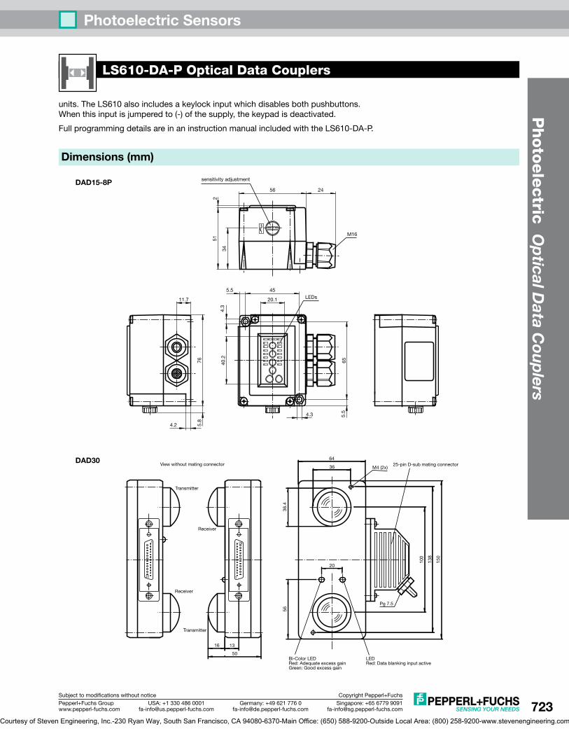
Dimensions (mm)
DAD15-8P
DAD30
sensitivityadjustment
M16
11.7
5.8
4.2
20.1
5.5
4.3
40.2
4.3 5.5
65
45
76
56 24
251
34
LEDs
Viewwithoutmatingconnector
Transmitter
Transmitter
Receiver
Receiver
Bi-ColorLEDRed:AdequateexcessgainGreen:Goodexcessgain
LEDRed:Datablankinginputactive
25-pinD-submatingconnector
36.4
Pg7.5
150
138
100
20
56
36
64
1316
50
M4(2x)
1
1 25
25
Courtesy of Steven Engineering, Inc.-230 Ryan Way, South San Francisco, CA 94080-6370-Main Office: (650) 588-9200-Outside Local Area: (800) 258-9200-www.stevenengineering.com
Page 14
P
hoto
ele
ctr
ic
Op
tica
l Dat
a C
oup
lers
Photoelectric Sensors
724 Singapore:[email protected]
USA:[email protected]
Germany:[email protected]
Pepperl+FuchsGroupwww.pepperl-fuchs.com
Subjecttomodificationswithoutnotice CopyrightPepperl+Fuchs
Dimensions (mm)
LS230
Telescopicsightglass
Transmitterlenses
Alignmentaid
receiverlens
LEDwindow(numberofLEDsvariesforeachseries)
T
T
R
54.5 15.5
54.5
25.5
70
35 31.5
12
2356
23
81
162
66
133
31
116
6 6
Pg9
LS610
BusINConnectorM12x1,5-pin
BusOUT/TerminationSocketM12x1,5-pin
PowerConnectorM12x1,4-pin
97.5
171
170
81
90
36
Courtesy of Steven Engineering, Inc.-230 Ryan Way, South San Francisco, CA 94080-6370-Main Office: (650) 588-9200-Outside Local Area: (800) 258-9200-www.stevenengineering.com
Page 15
P
hoto
ele
ctric
Op
tical Data C
oup
lersPhotoelectric Sensors
725Singapore:[email protected]
USA:[email protected]
Germany:[email protected]
Pepperl+FuchsGroupwww.pepperl-fuchs.com
Subjecttomodificationswithoutnotice CopyrightPepperl+Fuchs
Accessories(Dimensionsinmm)
Mounting Bracket Model OMH-DAD10for DAD15-8-P series.
Mounting Bracket Model OMH-LS230-DAincluded with LS230 and LS600 optical data couplers, shown below.
5.5(4x)
2.5
7.4+0.1(2x)17.5
2446
65
65
45
7662
10
25
ø8.2(2x)
230
33 44
130
193
See pages 855-896 for additional accessories
See pages 803-854 for cordsets
Mounting Bracket Model OMH-LS610-01for LS610 series. Allows fine adjustments in vertical and horizontal axes. LS610 quickly and securely mounts to bracket by spring clamp.
¯8.5
80
4426
200
100
100266
Verticalmovementadjustment
Horizontalmovementadjustment
Courtesy of Steven Engineering, Inc.-230 Ryan Way, South San Francisco, CA 94080-6370-Main Office: (650) 588-9200-Outside Local Area: (800) 258-9200-www.stevenengineering.com