Journal of the OPTICAL Of SOCIETY AMERICA VOLUME 47, NUMBER 12 DECEMBER, 1957 Optical Diffractometer for Facilitation of X-Ray Diffraction Studies of Macromolecular Structures* HAROLD W. WYCKOFF, RICHARD S. BEAR, RICHARD S. MORGAN, AND DIEGO CARLSTROM Department of Biology, Massachusetts Institute of Technology, Cambridge, Massachusetts (Received June 14, 1957) An instrument employing optical analogies to the diffraction of x-rays by macromolecular substances is described. Simple and readily obtainable components, materials and procedures are involved. Photographic methods are used to reduce the size of models for trial structures in forming masks whose optical diffraction is then compared with the x-ray diffraction of real structures. Conversely, the diffractometer can be employed to synthesize images of structures from masks simulating observed x-ray diffraction. Applications are described dealing with the investigation of helical chain molecules (polypeptide a helices, collagen and deoxyribonucleate molecules); with the study of larger sized structures exhibiting small-angle x-ray diffraction (e.g., collagen fibrils); and with image synthesis for centrosymmetric configurations (phthalocyanine). INTRODUCTION X-RAY diffraction methods for the resolution of fine structure differ very little in principle from microscopic methods.' In both cases there are two essential steps: (a) radiation of wavelength approximat- ing the sizes of the structural details to be resolved is allowed to impinge upon the object of interest, where- upon there emerges a diffraction pattern; (b) if lenses are available for the radiation employed, the diffraction effects may be recombined, in correct amplitudes and phases, to reconstruct an image. When lenses are not available, as in the x-ray case, artificial procedures must be used to provide the image. Since x-ray diffraction effects can be measured only in terms of intensities (squares of amplitudes) and phases are not experi- mentally available, a certain amount of ambiguity is inherent in the x-ray method. * This paper describes developments continuing over a period of years, supported in part by Research Grant C-1780 from the National Cancer Institute and in part by Grant G-2007 from the National Science Foundation. The current addresses of the authors are: H.W.W.: American Viscose Corporation, Marcus Hook, Pennsylvania; R. S. B.: Division of Science, Iowa State College, Ames; R.S.M.: Children's Medical Center, Boston; and D.C.: Karolinska Institutet, Stockholm, Sweden. ' M. J. Buerger, Proc. Natl. Acad. Sci. U.S. 27, 117 (1941). Because of the close similarity between ordinary optical and x-ray methods, the former are often useful in providing analogue methods for solution of diffraction problems. One may either (a) simulate a trial structure by formulation of a "mask," whose diffraction of visible light can be compared with the diffraction of x-rays by a given structure, or (b) assume and provide phases over an optical wavefront, resembling the original x-ray diffraction field, so that lenses may form the corresponding image. Trial structures or phase distributions are varied, respectively, until the observed x-ray diffraction is explained or until a reasonable image is produced. Bragg 23 was the first to use his "x-ray microscope" in these ways. The "Fly's Eye" camera (Bragg 4 ), later improved by Bunn' and Stokes 6 was also developed to facilitate the multiplication of unit cells in represent- ing crystal structures. Since then, other investigators 7 -13 2 W. L. Bragg, Nature 143, 678 (1939). 3 W. L. Bragg, Nature 149, 470 (1942). 4 W. L. Bragg, Nature 154, 69 (1944). 5 C. W. Bunn, Chemical Crystallography (Clarendon Press, Oxford, 1946). 6 A. R. Stokes, Proc. Phys. Soc. (London) 58, 306 (1946). 7 C. A. Taylor and H. Lipson, Nature 167, 809 (1951). 8 Taylor, Hinde, and Lipson, Acta Cryst. 4, 261 (1951). 9 H. Lipson and C. A. Taylor, Acta Cryst. 4, 458 (1951). )61 Copyright (D 1957by the Optical Societyof America.
Transcript
Journal of the
OPTICALOf
SOCIETYAMERICA
VOLUME 47, NUMBER 12 DECEMBER, 1957
Optical Diffractometer for Facilitation of X-Ray Diffraction Studiesof Macromolecular Structures*
HAROLD W. WYCKOFF, RICHARD S. BEAR, RICHARD S. MORGAN, AND DIEGO CARLSTROMDepartment of Biology, Massachusetts Institute of Technology, Cambridge, Massachusetts
(Received June 14, 1957)
An instrument employing optical analogies to the diffraction of x-rays by macromolecular substances isdescribed. Simple and readily obtainable components, materials and procedures are involved. Photographicmethods are used to reduce the size of models for trial structures in forming masks whose optical diffractionis then compared with the x-ray diffraction of real structures. Conversely, the diffractometer can be employedto synthesize images of structures from masks simulating observed x-ray diffraction.
Applications are described dealing with the investigation of helical chain molecules (polypeptide a helices,collagen and deoxyribonucleate molecules); with the study of larger sized structures exhibiting small-anglex-ray diffraction (e.g., collagen fibrils); and with image synthesis for centrosymmetric configurations(phthalocyanine).
INTRODUCTION
X-RAY diffraction methods for the resolution offine structure differ very little in principle from
microscopic methods.' In both cases there are twoessential steps: (a) radiation of wavelength approximat-ing the sizes of the structural details to be resolved isallowed to impinge upon the object of interest, where-upon there emerges a diffraction pattern; (b) if lensesare available for the radiation employed, the diffractioneffects may be recombined, in correct amplitudes andphases, to reconstruct an image. When lenses are notavailable, as in the x-ray case, artificial procedures mustbe used to provide the image. Since x-ray diffractioneffects can be measured only in terms of intensities(squares of amplitudes) and phases are not experi-mentally available, a certain amount of ambiguity isinherent in the x-ray method.
* This paper describes developments continuing over a periodof years, supported in part by Research Grant C-1780 from theNational Cancer Institute and in part by Grant G-2007 from theNational Science Foundation. The current addresses of theauthors are: H.W.W.: American Viscose Corporation, MarcusHook, Pennsylvania; R. S. B.: Division of Science, Iowa StateCollege, Ames; R.S.M.: Children's Medical Center, Boston; andD.C.: Karolinska Institutet, Stockholm, Sweden.
' M. J. Buerger, Proc. Natl. Acad. Sci. U.S. 27, 117 (1941).
Because of the close similarity between ordinaryoptical and x-ray methods, the former are often usefulin providing analogue methods for solution of diffractionproblems. One may either (a) simulate a trial structureby formulation of a "mask," whose diffraction ofvisible light can be compared with the diffraction ofx-rays by a given structure, or (b) assume and providephases over an optical wavefront, resembling theoriginal x-ray diffraction field, so that lenses may formthe corresponding image. Trial structures or phasedistributions are varied, respectively, until the observedx-ray diffraction is explained or until a reasonableimage is produced.
Bragg2 3 was the first to use his "x-ray microscope"in these ways. The "Fly's Eye" camera (Bragg4 ),later improved by Bunn' and Stokes6 was also developedto facilitate the multiplication of unit cells in represent-ing crystal structures. Since then, other investigators7 -13
2 W. L. Bragg, Nature 143, 678 (1939).3 W. L. Bragg, Nature 149, 470 (1942).4 W. L. Bragg, Nature 154, 69 (1944).5 C. W. Bunn, Chemical Crystallography (Clarendon Press,
Oxford, 1946).6 A. R. Stokes, Proc. Phys. Soc. (London) 58, 306 (1946).7 C. A. Taylor and H. Lipson, Nature 167, 809 (1951).8 Taylor, Hinde, and Lipson, Acta Cryst. 4, 261 (1951).9 H. Lipson and C. A. Taylor, Acta Cryst. 4, 458 (1951).
)61
Copyright (D 1957 by the Optical Society of America.
WYCKOFF, BEAR, MORGAN, AND CARLSTROM
I ~~~~~~~~~, ......I.......... .... _ _ _
.. IZ l \ f~ J L a. * v
Lo LML 2 C
s .
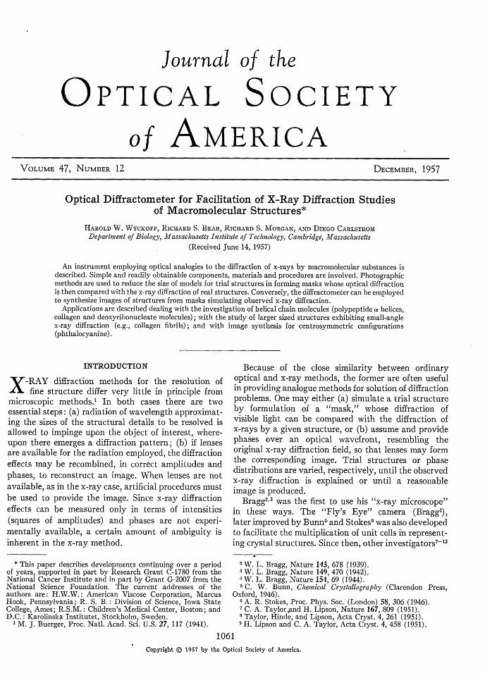
FIG. 1. The diffractometer, described as (above) a diagram ofparts, (middle) a diagram of optical function, and (below) aphotograph of the actual instrument. Labeling letters anddimensions are explained in the text.
have developed techniques for use of a "diffractionspectrometer," later termed "diffractometer," theinstrument today found in most widespread use,particularly in England.
Most of the applications thus far have been made tosubstances containing relatively simple molecules orwith few atoms per crystal unit cell. In recent yearsthe need for instruments capable of handling morecomplicated situations, such as are encountered inmacromolecular problems, has given rise to correspond-ing modifications for this purpose.'" 5 In this paper ispresented another scheme for handling multi-atomproblems, which is believed to have some advantagesin simplicity of construction and in ease of operation.Some novel applications are also described.
DIFFRACTOMETER
The diffractometer itself is first described, along withreasons for adopting principal design features. Figure 1shows schematically the elements employed, includingalso a photograph of the instrument as it appears onthe laboratory wall. Note that the entire optical trainis linear, to avoid the extra optical surfaces often usedby others for compactness. Inessential optical surfacesare to be avoided as much as possible, and the mountinglocation chosen was such that an extended length wasavailable without interference with other laboratoryequipment.
Reading from left to right, the elements are asfollows. The source S is the common AH-3 mercury arc;a combination of glass (Fl) and interference (F2) filters
10 Hanson, Taylor, and Lipson, Nature 168, 160 (1951).11 A. W. Hanson and H. Lipson, Acta Cryst. 5, 145 (1952)."2 A. W. Hanson and H. Lipson, Acta Cryst. 5, 362 (1952).
13 Hanson Li son, and Taylor, Proc. Roy. Soc. (London)A218, 371 (i953V.
41 A. Elliott and P. Robertson, Acta Cryst. 8, 736 (1955).c6 Hooper, Seeds, and Stokes, Nature 175, 679 (1955).
isolates the 5461 A green light, which is focused bylens Lo upon the entrance pinhole P (diameter normally0.1 mm, but sometimes as small as 0.05 mm). The lensesLi and L2 serve, respectively, to parallelize the lightfrom the pinhole and finally to form an image of thepinhole at the film casette C. Between the lenses isplaced the "mask" M, whose preparation is describedbelow. The lenses are of long focal length, 3 and 2 mrespectively, and are of two-inch aperture. The smallaperture requires rather small masks but also reducesthe area over which perfect optical surfaces are needed.The long focal lengths result in larger final opticaldiffraction patterns for a given size of mask. (In thisinstrument, diffraction radii measured in mm at thefilm are approximately reciprocals of the correspondingspacings at the mask, also expressed in millimeters.)Since monochromatic radiation is used and aperturesare small, readily available lenses can be used. The onesused here were provided by Mr. A. C. Hall, formerly ofthis Institute's Physics Department Optics Shop,and were selected for excellence of performance. Bothlenses are plano-convex, with plane surfaces turnedaway from the mask, an orientation which reducesspherical aberration to a minimum. It is estimated thatspherical aberration in this system is one-fifth the focaldepth of 2.2 mm. A separation of about 4 cm is leftbetween the lenses for insertion of a mask holder.
The film employed to register the diffraction patternsis Kodak Super Ortho-Press, with a resolution approxi-mating ninety lines per millimeter. Exposures arenormally of the order of a few minutes, but in specialinstances run as high as several hours. Although nospecial precautions are taken against thermal changesand vibration, other than the choice of a stable wallaway from laboratory drafts, there is no great incon-venience normally encountered from these factors.The whole optical train, from entrance pinhole tofilm casette, is enclosed in black fiberboard tubing of 10cm diam, so that routine operation is possible indaylight.
Lenses, as well as pinhole and casette holders, arepermanently mounted, but new pinholes, film-loadedcasettes and masks may be introduced as required.The original diffraction patterns are subsequentlyenlarged tenfold by ordinary photographic processesto obtain prints satisfactory for most purposes, althoughthe original film can be studied microscopically whennecessary.
It is possible to view the diffraction directly in thediffractometer by means of a low-power ocular. Used inthis way, with simple masks punched by needles incardboard to simulate various types of diffractionproblem, the diffractometer can serve as a valuableeducational device.
PREPARATION OF MASKS
The heart of any diffractometer procedure is themask, which generally consists of holes distributed over
Vtol. 471062
OPTICAL DIFFRACTOMETER
an opaque background to resemble the arrangement ofatoms in a proposed structure or to simulate thedistribution of radiation over a previously obtainedx-ray diffraction pattern. Not only must the maskbe made accurately but it must also be handled care-fully, since very slight imperfections in optical pathreadily introduce distortions in the final result.
Essentially two different means are available forobtaining satisfactory "holes" for masks; punchingprocesses to open clear areas in an opaque board, orphotographic means of leaving an unsilvered areaagainst a black background. Punching procedures havebeen employed by Lipson and his colleagues becauseof the advantages of speed and the production ofoptically clear holes. Punches have the disadvantagethat there are limitations to the smallness of hole sizeobtainable. Consequently, the concentration of holesthat can be produced to represent complex structuresis not great. On the other hand, photographic filmsand plates, while permitting small-scale reproductionof quite complex and varied patterns, normally arenot sufficiently uniform optically to present constantoptical paths over entire mask areas. One can, however,take special steps to remedy this difficulty. Bragg andStokes6 early introduced the imprisonment of thefilm or plate between optical flats, with immersion oilserving to even out optical path differences. Bragg3
used also a "filmless" photographic process whichleft no emulsion over an optically true glass backingwherever no exposure had occurred. Hooper, Seeds,and Stokes'" more recently employed for similar purposea process in which the emulsion could be stripped andplaced on an optical fiat, after the gelatin was removedfrom unexposed areas.
Photographic procedures are essential for maskformation when large and complex structures are to bestudied. They allow easy reduction in mask size so thatsmall apertures may be employed in the diffractometerlenses. Of the two methods of controlling optical path,the one which forms the immersion sandwich betweenoptical flats employs more readily available materialsand simpler techniques. One can employ judiciousvariations from the procedures described below, butthe importance of correct mask formation is so greatthat a detailed description of a valid method is useful.In spite of the number of steps that are involved, inpractice relatively unskilled operators can carry throughexamination of a given structure in a day or two,which may be regarded as rapid for the complexsystems often involved.
Preparation of the Model Projection
Although one can consider any continuous ordiscontinuous distribution of matter that can beexpressed as a drawing in black or white or in tones of
16 W, L, Bragg and A. R. Stokes, Nature 156, 332 (1945).
gray, the most frequently encountered structures arethose depicted in terms of actual atoms. The methodsemployed can therefore most conveniently be describedin terms of procedures for structures of this type.
One approaches the problem with a set of atomcoordinates and chooses a plane upon which theseare to be projected in order to obtain a two-dimensionalfigure. The projection is constructed on tracing paperor other transparent or translucent background at ascale of one centimeter per angstrom unit. Mostmacromolecular substances do not yield x-ray diffrac-tion corresponding to Bragg spacings smaller than about1.5 A, so that this scale offers ample opportunity tointroduce all the detail that is useful.
The problem of how to represent atoms in theprojections so that they will scatter visible light likereal atoms scatter x-rays has been discussed in particularby de Vos.17 He points out that simple circular spotsrepresenting different kinds of atoms cannot be madeto match optically the variation in amplitude of x-rayscatter with increasing scattering angle. In actualpractice one can, with reasonable satisfaction, adopt theprocedure of allowing circular areas representing eachatom to be proportional to their scattering at zeroangle and small enough so that the amplitude scatteredover all useful diffraction angles does not diminishgreatly. On the other hand one desires as large holesas possible in the final mask to permit as much lightto be passed as possible.
In most of the systems studied here, the atoms ofcarbon, nitrogen and oxygen are encountered mostfrequently, and these have been considered to be ofessentially equal scattering power, hence represented bythe same sized spots. Hydrogen atoms are generallyneglected and indeed are often distributed in fact so asto make the scattering from the neighborhood of C,N, and 0 atoms more nearly equivalent. The spotdiameter adopted on the original projection for thesethree types of atom is 5 mm, corresponding to a sizeof 0.5 A, which is well below the generally usefulresolution.
Sometimes the suggestion of de Vos7 regarding theuse of annular atoms has been adopted. In these cases,the annuli are constructed to match individual atomstructure factors at zero scattering angle and at oneother angle. Table I shows the dimensions of the
annulus of each of five commonly encountered atoms,selected so that the scattering is correct centrally aswell as at a diffraction angle corresponding to Braggspacings of 3.3 A. Internal and external radii given inthe table correspond to the inner and outer edges of theannulus, which is blackened between these positionsas drawn on the original projection. An example ofthe use of annular atoms is given by Bear.8
In complex structures one often encounters over-lapping atoms. While there are several methods thatcould be employed, such as placing the overlappingatoms in different cells of the structure, we havepreferred simply to enlarge the spots when circularatoms are employed, or to tolerate overlapping in thecase of the annular atoms, since relatively small areasare then lost. In the former case, spot radii are increasedin such a way that area is proportional to the totalnumber of electrons on the overlapping atoms, and thelarger spot is placed at the center of gravity of the atomsthus represented. Results obtained with overlappingannular atoms sometimes show objectionable evidenceof anisotropic scattering by individual atoms.
Single Cell and Its Size Reduction
Most structures that are to be investigated consistof a unit pattern or cell which is repeated in one ortwo directions in the plane of the projection. In earlywork, in order to reduce the number of atoms whichneeded to be placed individually into a structure,the "Fly's Eye" camera' provided a means for multiplyreproducing a single cell. Hanson and Lipson" pointedout that one can work with a single cell or a relativelysmall number of cells for most purposes.
In the present procedure the single cell is formulatedas a collection of atoms at the scale 1 cm= 1 A, and theboundaries of the cell are marked. The single-cellprojection is laid on an opal glass behind which fluores-cent lamps have been placed in such a way as to insureeven illumination over a known useful area. A Goertzapochromat lens, f:9.5, fixed in a special camera isused to photograph the cell at tenfold reduction. Atthis stage the resolution of the lens (5 g) and theedge "creep," at normal exposure and developmentconditions for the Kodalith Ortho Thin Base filmused, do not alter the atom spot dimensions more thanabout 10 . The original cell projection consists ofblack atoms against a white background, and thereduced cell is now in the form of a negative with whiteatoms against a black background.
Multiprinting Operation
The diffraction by a single cell could be used, butgreater speed can be obtained when several cells arecombined to allow more light through the mask. Onecan reproduce cells according to a two-dimensional
18 R. S. Bear, J. Biophys. Biochem. Cytol. 2, 363 (1956).
projection of the appropriate lattice, but in manymacromolecular problems it is sufficient simply torepeat the units of a single molecular chain along theaxis of the chain, to obtain a mask which will providethe diffraction pattern of a single chain molecule.Here, from five to eight units are "multiprinted" inlinear array by simple movement of the receivingKodalith film under a standard enlarger, which projectsthe single-unit negative described above. Accomplish-ment of the multiprinting process in an accurate manneris facilitated by sliding the receiving film along a metalrule on which arresting pegs are placed in appropriateholes of a closely spaced series to furnish accuratetranslations corresponding to the single-unit length.The single-unit enlargement is approximately 1.4 timesbut is more accurately selected to match a convenientpeg separation with the cell boundary marks. Theresult of the multiprinting operation is a positivereproduction of units in tandem.
During this process the multiprint is exposed, ateach step, ten to fifteen times normal exposure. Experi-ence has shown that this overexposure will cause blackborders to move into white areas 40 to 50 /t. Thisedge creep is chosen in anticipation of a similar reversecreep of one-tenth the amount later in further reducingthe picture to final mask size. The overexposure alsoensures that atom spots and background will be verymarkedly different in density.
Final Reduction
Again one uses the fixed camera for tenfold furtherreduction to make the final mask. Kodalith film isstill used, this time at exposure and developmentchosen to yield a dense background but minimal creep.Results are checked under a microscope to confirm thatthe negative exhibits reasonably accurate maintenanceof the original relative spot sizes and separations. Inthis final mask the scale will be approximately 0.14mm=1 A, corresponding to an over-all reduction ofabout seventy times from the original projection.One now has a negative in which atoms are clearspaces against a dense background.
Insertion of the Mask into the Diffractometer
The mounting of the mask with immersion fluidbetween optical flats is possibly the most crucialoperation in the whole procedure. Small unevennessesor burs, left by punching of identification notches orby trimming of mask edges, can distort the sandwichsufficiently to cause trouble. To avoid these difficultiesthe glass flats, which are disks of two-inch diameter andone-fourth-inch thickness, are bevelled at their adjacentedges so that the circularly cut mask film can beinserted in the sandwich with its edges within thebevelled regions, beyond the facing surfaces of theflats. The flats were made with outer surfaces, as
Vol. 471064
OPTICAL DIFFRACTOMETER
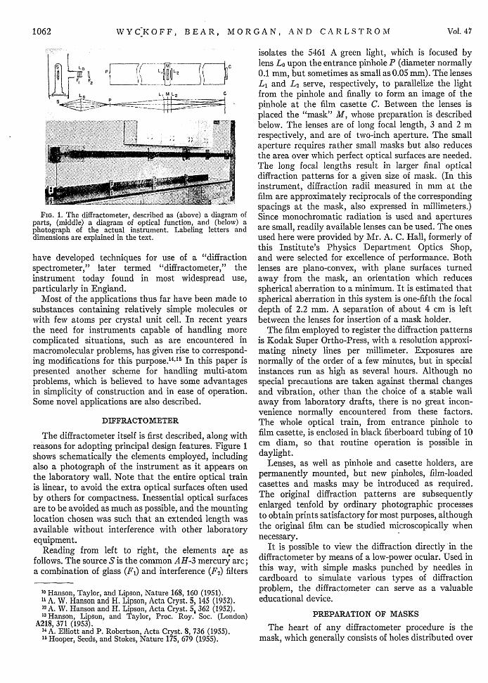
FIG. 2. Mask and transform for the 5-turn, 18-residue poly-peptide a helix, with carbon atoms at positions corresponding toL residues in a right-hand helix. On the left is the positive of asingle 5-turn unit which, when repeated five times verticallyand reduced in size (see text), provides the mask (negative)yielding the optical transform shown partially on the right.The 5th, 13th and 18th layer lines are identified.
placed in the sandwich, true to 1/10 X. The innersurfaces were not as critical and tolerance was kept to1/4 X. The flats are held together by springs, which mustbe as light as possible to avoid bending the flats. Thelatter possibility is also lessened if the mask film coversthe entire surface between the flats. Black masking tapecan be used outside the sandwich to cover blemishesaround the useful area of the mask, or to alter the areaunder examination.
Typical Result
Figure 2 furnishes an example of the application ofthe methods described above. The structure involvedis the 5-turn, 18-residue a helix described by Paulingand Corey.'9 In this instance are included the main-chainatoms of the polypeptide, plus carbon atoms torepresent simple side chains; the structure is essentiallythat of polyalanine. Location of the i carbon atom ineach residue corresponds to the first position givenby Pauling and Corey in their table of atomic co-ordinates, which is valid for L residues in a right-handedhelix. The result for left-handed configuration of Lresidues is depicted in Fig. 3. Recent polarimetricstudies of polypeptides'2 ' , favor the right-handedmodels for synthetic and native a structures, althoughearlier x-ray diffraction studies had suggested theleft-handed form for poly-'y-methyl-L-glutamate.'2
RELIABILITY OF RESULTS
Although the usefulness and reliability of opticaldiffraction methods have been demonstrated by otherson numerous occasions, it is of some interest in develop-ing any particular instrument to confirm that itsoperation is trustworthy. Various simple tests can andhave been made with the present apparatus, such asthe examination of the "antipoint" (image) of the
1 L. Pauling and R. B. Corey, Proc. Natl. Acad. Sci. U. S. 37,235 (1951).
20 J. T. Yang and P. Doty, J. Am. Chem. Soc. 79, 761 (1957).21 C. Cohen and A. G. Szent-Gyorgyi, J. Am. Chem. Soc. 79,
248 (1957).22 Yakel, Pauling, and Corey, Nature 169, 920 (1952).
entrance pinhole formed through the full aperture of thelenses and the optical flats, as well as the antipointsformed by square, rectangular, or other simple aperturesinserted at the mask position. We have also registeredthe diffraction by projections of continuous helicalfigures, which were found to yield results consistent withthe theory developed by Cochran, Crick, and Vand."3All of these simple tests yielded considerable confidencein the performance of the diffractometer.
The reliability of the methods for forming macro-molecular projections into masks has been demonstratedby calculation and by comparison with results obtainedby others. For example, the optical diffraction patternsfor the alpha polypeptide helices of Pauling and Corey,'9photographed by using the methods of Elliott andRobertson,'4 were kindly sent to us by Dr. Elliott andproved to be essentially indistinguishable from onesobtained here (Figs. 2 and 3) for the same structures.The diffractometer used by these other investigators isphysically very different from the present one, sincethe former instrument contains a single reflectingoptical element (rather than lenses) at very wideaperture, and the masks are of relatively large scalewith atoms represented by small holes punched intoan opaque background.
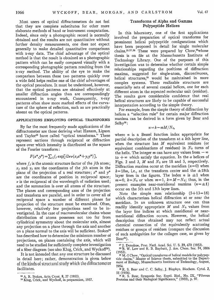
Figure 3 further demonstrates the close corre-spondence between the optical diffraction of one formof a helix and the transforms calculated for thisstructure by Pauling, Corey, Yakel, and Marsh.2 4 Inthis figure, one quadrant of the optical diffractionpattern is reproduced and the dotted lines are used toindicate the regions along each layer line at whichthe calculated transform indicates appreciable intensityshould be observed. The correspondence betweenoptical diffraction and the calculations is striking,even though the calculations distinguished the severalkinds of atoms involved and allowed for the variationof atomic structure factors with scattering angle,precautions which were not taken with the opticalprocedures.
FIG. 3. Comparisonof transforms, ob-
13 ~~~~~~~~~tained optically andby calculation, forthe a helix corre-sponding to L re-
* ~~~~~~~~~~~sidues in a left-handhelix. Layer-line in-dices are given onthe left and radial
*. coordinates (r*) in...000;00- -,2200009 .09} .S . 0 reciprocal (diffrac-tion) space are ab-scissae.
23 Cochran, Crick, and Vand, Acta Cryst. 5, 581 (1952).24 Pauling, Corey, Yakel, and Marsh, Acta Cryst. 8, 853 (1955),
December 1957 1065
WYCKOFF, BEAR, MORGAN, AND CARLSTROM
Most users of optical diffractometers do not feelthat they are complete substitutes for other moreelaborate methods of hand or instrument computation.Indeed, since only a photographic record is normallyobtained and the results are not quantitative withoutfurther density measurements, one does not expectgenerally to make detailed quantitative comparisonswith x-ray data. The chief advantage of the opticalmethod is that the result is obtained as a photographicpattern which can be easily compared visually with acorresponding photographic pattern resulting from thex-ray method. The ability of the eye to make thecomparison between these two patterns quickly overa wide field helps realize one of the chief advantages ofthe optical procedure. It must be understood, however,that the optical patterns are obtained effectively atsmaller diffraction angles than are correspondinglyencountered in x-ray work, Consequently, x-raypatterns often show more marked effects of the curva-ture of the sphere of reflection, such as are practicallyabsent on the optical patterns.
APPLICATIONS EMPLOYING OPTICAL TRANSFORMS
By far the most frequently made applications of thediffractometer are those deriving what Hanson, Lipsonand Taylor'3 have called "optical transforms." Theserepresent sections through reciprocal or diffractionspace over which intensity is distributed as the squareof the Fourier transform:
F(x*,y*) =Ej expEi2,,rv(xjx*+yjy*)],
where fj is the atomic structure factor of the jth atom;xj and yj are the coordinates of the jth atom in theplane of the projection of a real structure; x* and y*are the coordinates of position in reciprocal space;v is the reciprocal of the wavelength of radiation used;and the summation is over all atoms of the structure.The planes and corresponding axes of the projectionand transform are parallel, and in order to cover all ofreciprocal space a number of different planes forprojection of the structure must be examined. Often,however, relatively few projections need to be in-vestigated. In the case of macromolecular chains whosedistribution of atoms possesses not too far fromcylindrical symmetry about the molecular axis, almostany projection on a plane through the axis and anotheron a plane normal to the axis will be sufficient. Stokes25
has described how to determine the minimum number ofprojections, on planes containing the axis, which willneed to be studied for sufficiently complete investigationof a fiber diagram (see also Klug, Crick, and Wyckoff26).
It is not intended that any one structure be discussedin detail here; rather, demonstration is given belowof the kinds of structural study which the diffractometer
facilitates.
23 A. R. Stokes, Acta Cryst. 8, 27 (1955).26 Klug, Crick, and Wyckoff, in preparation, 1957.
Transforms of Alpha and GammaPolypeptide Helices
In this laboratory, one of the first applicationsinvolved the preparation of optical transforms forprominent helical polypeptide configurations whichhave been proposed in detail for single molecularchains. 9 27 28 These were prepared by Chow,2 whosethesis is on file at the Massachusetts Institute ofTechnology Library. One of the purposes of thisinvestigation was to determine whether certain simplerelationships regarding the positions of diffractionmaxima, suggested for single-atom, discontinuous,helical structures,23 would be maintained in morecomplex systems. These realizable structures areessentially sets of several coaxial helices, one for eachdifferent atom in the repeated molecular unit (residue).The results gave considerable confidence that realhelical structures are likely to be capable of successfulinterpretation according to the simple theory.
For example, from the simple theory of diffraction byhelices a "selection rule" for certain major diffractionmaxima can be derived in a form given by Bear andSelby'0 :
it = k - M/No,
where n is a Bessel function index appropriate forpartial description of the transform at a kth layer line,when the structure has M equivalent residues (orequivalent combinations of residues) in No turns ofthe helix. The integer m can have any values from -o
to + co which satisfy the equation. In the a helices ofFigs. 2 and 3, M and No are 18 and 5, respectively.Diffraction maxima occur at the meridian (n=0) whenk=18m, i.e., at the transform center and the 18thlayer lines in the figures. The index n is ± 1 whenIn=0, k=No or when m=1, k=M-No; thus, in thepresent examples near-meridional maxima (= i1)occur on the 5th and 13th layer lines.
Note the simple sum relationship (5+13=18)which characterizes helical diffraction at or near themeridian. In an unknown structure one can thusreadily identify appropriate M and No values fromthe layer line indices at which meridional or near-meridional diffraction occurs. However, the helicaldescription thus obtained may not reflect actualchemical connection of the equivalently scatteringresidues or groups of residues (compare the discussionof such ambiguities for the collagen case, as given byBear3 ).
27 J. Donohue, Proc. Natl. Acad. Sci. U. S. 39, 470 (1953).28 B. W. Low and R. B. Baybutt, J. Am. Chem. Soc. 74, 5806
(1952).29 M.-I Chow, "Optical transforms of helical models for polypep-
tide chains," Master of Science thesis, submitted to the Depart-ment of Biology, Massachusetts Institute of Technology, August,1954.
30 R. S. Bear and C. C. Selby, J. Biophys. Biochem. Cytol. 2,55 (1956).
31 R. S. Bear, Symposia Soc. Exptl. Biol., No. IX, "FibrousProteins and their Biological Significance," (1955), p. 97.
Vol. 471066
OPTICAL DIFFRACTOMETER
Testing of Proposed Collagen Structures
In recent years a series of detailed models for themain-chain configuration of collagen molecules hasappeared. Each of these has been subjected to prepara-tion of the corresponding optical transforms, generallyfor projections both along and normal to the molecularaxis. For example, one of the earliest models which wasconsistent with the gross helical features appropriatefor collagen was proposed by Crick.32 Optical testsof this structure" made the correctness of this structureseem highly unlikely. Eventually, however, moresuccessful three-chain, coiled-coil models were derivedby a number of investigators.'
In the testing of the three-chain structures, theoptical transforms did much to provide assurance of theessential correctness of the proposed models. However,it must be said that the experience gained during theevolution of the collagen structure rather suggests thatthe optical examinations provide useful rather thansufficient tests for protein structures. Detailed agree-ment between optical and x-ray patterns is not easy toobtain for proteins, since current information regardingside-chain distribution is lacking for most proteins,and also because x-ray diffraction patterns themselveslack as much detail as is present in optical transformsof test structures. The latter generally neglect possibleeffects of irregular distributions of side-chains or othersources of randomness.
Investigations of Polynucleotide Structures
During an investigation into the correctness of thehelical structure for deoxyribonucleic acid (DNA), asoriginally proposed by Crick and Watson,3 3 Wyckoff3 4
made extensive use of optical procedures. We note heretwo features of this study. The B type modificationsof DNA, which were of primary interest, are foundin highly hydrated fibers. Therefore, instead of beingrepresented as containing the full normal complementof electrons, atoms were depicted as the differencebetween the electrons in comparable volume of waterand the number actually carried by each atom.Areas of atom spots in the projections were madeproportional to this difference. It was also foundconvenient to form optical transforms for variousprotions of the DNA structure separately, such as thephosphate-ribose backbone and the organic-base sidechains. Thus one could conclude which parts of recip-rocal space were being contributed to by the separateportions of the structure and to alter pertinent struc-tural details accordingly. Wyckoff's final conclusions
32 F. H. C. Crick, J. Chem. Phys. 22, 347 (1954).33 F. H. C. Crick and J. D. Watson, Proc. Roy. Soc. (London)
A223, 80 (1954).34 H. W. Wyckoff, "X-ray diffraction analysis of the structure of
deoxyribonucleic acid," Ph.D. thesis, submitted to the Depart-ment of Biology, Massachusetts Institute of Technology (June,1955).
FIG. 4. Illustrating a method for direct determination ofdiffraction-order phases for one-dimensional arrays. The twoidentical arrays on the left (consisting of long periodic "back-grounds" with superimposed "bands") are antiparallel, withcenters of symmetry marked by extra blocks between the arrays.On the right is the optical transform of this system. As explainedin the text, phases are measured by distances of the heavy spotsat each layer line (identified by white dots) from the meridian(vertical midline). The zero-order layer is the lowest one.
were similar to those independently reached by Feughel-man, Langridge, Seeds, Stokes, Wilson, Hooper,Wilkins, Barclay and Hamilton.3 5
Application to Study of Gross FibrillarStructure of Collagen
An advantage of photographic methods of maskpreparation is illustrated by the investigation of Bearand Morgan,3" who studied the supra-atomic featuresof electron distribution of matter along collagen fibrils.Here atomic sizes are way below the scale of structuraldetail corresponding to small-angle x-ray diffractionof collagen, so that block-like representations ofmasses corresponding to "bands" and "background"were employed (see Fig. 4). Patterns of band andbackground distribution along a linear array wereused to simulate the fibril. When model diffractionresembled the observed small-angle x-ray diffraction,the model was said to represent satisfactorily the mainfeatures of distribution of matter along the real fibril.Finally, phases for the several diffraction orders werecalculated and used along with measured x-ray intens-ities to construct smooth electron density plots as afunction of position along the fibril axis. The modelsand transforms produced by this investigation havealready been published, but we wish here to callattention to two novel developments in transformtreatment which accompanied this work.
One of these involved a means of investigating, on asingle optical transform, the result of the relativeshifting of two separate arrays, one representingfibrillar bands and the other standing for backgrounddensity. By placing these two arrays, with axes parallel
36 R. S. Bear and R. S. Morgan, in Symposium on ConnectiveTissue, London, July, 1956 (to be published).
1067December 1957
WYCKOFF, BEAR, MORGAN, AND CARLSTROM
but separated, together on the diffractometer mask,a simple inspection of the resulting optical transform,at various angles through its center, readily revealedthe effects upon the relative intensities of the severallayer lines corresponding to various projections of onearray upon the other. It then became easy to decidewhich projection of background against band patternresembled the x-ray situation and thus to concludeat which point the background should be placed overthe band system in the final model. An example of thisprocedure has been reproduced in the published paper.3 6
Although it is not too difficult to calculate phases fordiffraction by simple arrays of block-like clumps ofmatter, we found it was possible to make the phasedetermination optically in a very straightforwardmanner. Figure 4 illustrates this procedure. Two arraysof equal structure, each containing band and back-ground blocks superimposed directly, are placed inanti-parallel orientation with appreciable lateral separa-tion between their axes. The levels along each arraywhich are selected to be the origin of each cell arekept at the same height in both arrays, and at theselevels are also placed additional blocks marking centersof symmetry for the entire mask. Because of thecentrosymmetric nature of the mask, the resultingoptical transform contains, along its vertical axis,amplitudes at each layer line which are in phase withthe center of the zero-order layer. Fringes occur alongeach layer line as maxima and minima separatedinversely as the lateral distance between the two arraysof the mask. Two adjacent fringes on each layercorrespond to phase difference of a whole cycle. Themarkers at the centers of symmetry in the mask resultin distinguishing which of the two maxima per cyclecorrespond to positive amplitude. As one reads up themeridian of the transform one can, at each layer line,measure the shift of the strong maximum from themeridian as fractions of the double-fringe extension.These fractional shifts are fractions of the cycle 2r,representing directly the relative phase angles applicableto each diffraction order in the transform of a singlearray.
This method resembles a procedure for deriving realand imaginary parts of transforms for centrosymmetric,two-dimensional structures by centrosymmetric addi-tions to the mask, originally proposed by Hanson,Lipson and Taylor,3 (1953). The procedure can beused as simply as has been illustrated here only forone-dimensional arrays.
OPTICAL FOURIER SYNTHESIS
The optical diffractometer can also be used toaccomplish the reverse of the procedure describedabove, namely, to synthesize images of the structurefrom masks containing the x-ray diffraction data. Inthis application the mask consists of a grid of holeswhose areas are proportional to amplitudes of the
x-ray reflections in one plane of reciprocal space, andthe image formed in the diffractometer is essentiallythe square of the Fourier electron density plot, pro-jected on a parallel plane of the real structure. Anapplication of this sort was made by Bragg2 for diopside,and similar other developments have been introducedby Buerger,3 7 by Hanson, Taylor, and Lipson,0 byHanson and Lipson,2 and most recently by Dunkerleyand Lipson.3"
In the most general case one requires a means ofintroducing appropriate individual phase shifts to thelight passing through every hole of the mask. Buergeraccomplished this by tilting mica plates over eachhole, but in structures having centers of symmetry,phase requirements reduce to only two phase possibil-ities, determining whether positive or negative ampli-tude shall be given to light passing through each hole.In the diopside structure the signs for the projectionsynthesized by Bragg were all positive, because of apreponderance of heavy atoms at the centers of sym-metry, so that no phaseshifting device was necessary.Hanson and Lipson employed X/2 mica plates, betweenpolarizers and analyzers, to select, for equal-sizedmask holes, correct amplitudes as well as positive ornegative signs. Syntheses of hexamethylbenzene anddurene were made in this way. A simpler procedure wasfollowed by Dunkerley and Lipson for nickel phthalo-cyanine. In this structure, since the nickel atoms are atcenters of symmetry, nearly all reflections have positivesign, and a small shift of scale, so that all amplitudesbecome positive, in effect increases the weight of theheavy metal atom without corresponding changes inthe remainder of the molecule.
Dunkerley and Lipson do not explicitly state that asimilar procedure is possible, even when atoms do not
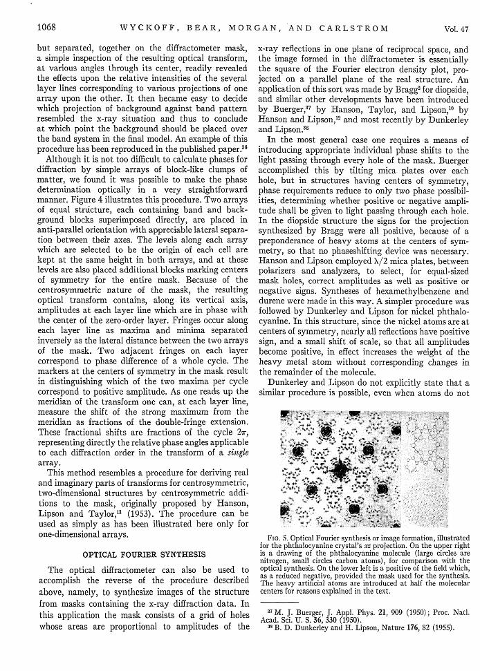
FIG. 5. Optical Fourier synthesis or image formation, illustratedfor the phthalocyanine crystal's xz projection. On the upper rightis a drawing of the phthalocyanine molecule (large circles arenitrogen, small circles carbon atoms), for comparison with theoptical synthesis. On the lower left is a positive of the field which,as a reduced negative, provided the mask used for the synthesis.The heavy artificial atoms are introduced at half the molecularcenters for reasons explained in the text.
37 M. J. Buerger, J. Appl. Phys. 21, 909 (1950); Proc. Natl.Acad. Sci. U. S. 36, 330 (1950).
38 B. D. Dunkerley and H. Lipson, Nature 176, 82 (1955).
1068 Vol. 47
OPTICAL DIFF
exist at symmetry centers, but such is the case. Toillustrate this point Fig. 5 shows the result of takingthe (hOl) data of Robertson3 9 for phthalocyanine(without heavy metal constituents), adding a constantpositive term (equal in magnitude to the maximumnegative amplitude involved) to all reflections except(000), and synthesizing the corresponding opticalimage. In this procedure, reflections which were ofzero amplitude originally, either accidentally or becauseof space group extinctions, were given amplitude equalto the added term. The diffractometer result is animage of the xz projection, containing artificial heavy"atoms" at one center of symmetry per cell. Inclusion
39 J. M. Robertson, J. Chem. Soc. 1936, 1195.
RACTOMETER, 1069
of the reflections which would normally be absentbecause of space group requirements cuts out heavyatoms at the centers of half of the molecules, allowingat least these to be seen without interference from theartificially inserted heavy atoms.
In this laboratory application of the diffractometermethods has been made to the structure of chitin ina most complete manner. Optical transforms wereused to test successively refined structures; signs ofreflection amplitudes, corresponding to a useful centro-symmetric projection, were determined optically; andfinally an image of this projection, containing artificialheavy atoms, was synthesized. This work will bedescribed in another place (Carlstrom4 0 ).