Mechatronics Optical Encoders K. Craig 1 Optical Encoders • Any transducer that generates a coded reading of a measurement can be termed an encoder. • Shaft Encoders are digital transducers that are used for measuring angular displacements and velocities. • Relative advantages of digital transducers over their analog counterparts: – High resolution (depending on the word size of the encoder output and the number of pulses per revolution of the encoder) – High accuracy (particularly due to noise immunity of digital signals and superior construction)
Transcript
MechatronicsOptical Encoders
K. Craig1
Optical Encoders• Any transducer that generates a coded reading of a
measurement can be termed an encoder.
• Shaft Encoders are digital transducers that are used for measuring angular displacements and velocities.
• Relative advantages of digital transducers over their analog counterparts:– High resolution (depending on the word size of the
encoder output and the number of pulses per revolution of the encoder)
– High accuracy (particularly due to noise immunity of digital signals and superior construction)
MechatronicsOptical Encoders
K. Craig2
– Relative ease of adaptation in digital control systems (because transducer output is digital) with associated reduction in system cost and improvement of system reliability
• Shaft Encoders can be classified into two categories:– Incremental Encoders
– Absolute Encoders
• Incremental Encoders– Output is a pulse signal that is generated when the
transducer disk rotates as a result of the motion that is being measured.
MechatronicsOptical Encoders
K. Craig3
– By counting pulses or by timing the pulse width using a clock signal, both angular displacement and angular velocity can be determined.
– Displacement, however, is obtained with respect to some reference point on the disk, as indicated by a reference pulse (index pulse) generated at that location on the disk. The index pulse count determines the number of full revolutions.
• Absolute Encoders– An absolute encoder has many pulse tracks on its
transducer disk.
– When the disk of an absolute encoder rotates, several pulse trains – equal in number to the tracks on the disk – are generated simultaneously.
MechatronicsOptical Encoders
K. Craig4
– At a given instant, the magnitude of each pulse signal will have one of two signal levels (i.e., a binary state) as determined by a level detector. This signal level corresponds to a binary digit (0 or 1). Hence, the set of pulse trains gives an encoded binary number at any instant.
– The pulse windows on the tracks can be organized into some pattern (code) so that each of these binary numbers corresponds to the angular position of the encoder disk at the time when the particular binary number is detected.
– Pulse voltage can be made compatible with some form of digital logic (e.g., TTL)
– Direct digital readout of an angular position is possible.
MechatronicsOptical Encoders
K. Craig5
– Absolute encoders are commonly used to measure fractions of a revolution. However, complete revolutions can be measured using an additional track that generates an index pulse, as in the case of an incremental encoder.
• Signal Generation can be accomplished using any one of four techniques:– Optical (photosensor) method
– Sliding contact (electrical conducting) method
– Magnetic saturation (reluctance) method
– Proximity sensor method
• Focus on Optical Method: signal generation and signal interpretation and processing (same for all four types of signal generation).
MechatronicsOptical Encoders
K. Craig6
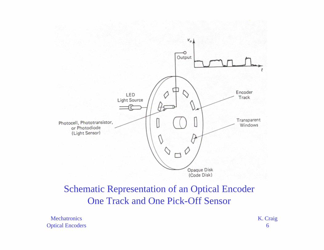
Schematic Representation of an Optical EncoderOne Track and One Pick-Off Sensor
MechatronicsOptical Encoders
K. Craig7
Schematic Diagram of anAbsolute Encoder Disk
Pattern(a) Binary code(b) Gray code
MechatronicsOptical Encoders
K. Craig8
Schematic Representation of a Sliding Contact Encoder
MechatronicsOptical Encoders
K. Craig9
Schematic Representation of a Magnetic Encoder
Pulse peak: nonmagnetic areaPulse valley: magnetic area
MechatronicsOptical Encoders
K. Craig10
Schematic Representation of a Proximity Probe Encoder
Proximity sensor:Magnetic induction or
Eddy current
MechatronicsOptical Encoders
K. Craig11
• Elements of the Optical Encoder– The optical encoder uses an opaque disk (code disk)
that has one or more circular tracks, with some arrangement of identical transparent windows (slits) in each track.
– A parallel beam of light (e.g., from a set of light-emitting diodes) is projected to all tracks from one side of the disk.
– The transmitted light is picked off using a bank of photosensors on the other side of the disk that typically has one sensor for each track.
– The light sensor could be a silicon photodiode, a phototransistor, or a photovoltaic cell.
MechatronicsOptical Encoders
K. Craig12
– Since the light from the source is interrupted by the opaque areas of the track, the output signal from the probe is a series of voltage pulses. This signal can be interpreted to obtain the angular position and angular velocity of the disk.
– Note that an incremental encoder disk requires only one primary track that has equally spaced and identical window (pick-off) areas. The window area is equal to the area of the inter-window gap. Usually, a reference track that has just one window is also present in order to generate a pulse (known as the index pulse) to initiate pulse counting for angular position measurement and to detect complete revolutions.
MechatronicsOptical Encoders
K. Craig13
– In contrast, absolute encoder disks have several rows of tracks, equal in number to the bit size of the output data word. Furthermore, the track windows are not equally spaced but are arranged in a specific pattern on each track so as to obtain a binary code (or gray code) for the output data from the transducer.
– It follows that absolute encoders need as least as many signal pick-off sensors as there are tracks, whereas incremental encoders need one pick-off sensor to detect the magnitude of rotation and an additional sensor at a quarter-pitch separation (pitch = center-to-center distance between adjacent windows) to identify the direction of rotation, i.e., the offset sensor configuration.
MechatronicsOptical Encoders
K. Craig14
– Some designs of incremental encoders have two identical tracks, one a quarter-pitch offset from the other, and the two pick-off sensors are placed radially without any circumferential offset, i.e., the offset track configuration.
• Signal interpretation depends on whether the particular optical encoder is an incremental device or an absolute device.– We will focus on the incremental optical encoder.
– The output signals from either the offset sensor configuration or the offset track configuration are the same.
MechatronicsOptical Encoders
K. Craig15
– Note that the pulse width and pulse-to-pulse period (encoder cycle) are constant in each sensor output when the disk rotates at constant angular velocity. When the disk accelerates, the pulse width decreases continuously; when the disk decelerates, the pulse width increases continuously.
– The quarter-pitch offset in sensor location or track position is used to determine the direction of rotation of the disk. It is obtained by determining the phase difference of the two output signals, using phase-detection circuitry. One method for determining the phase difference is to time the pulses using a high-frequency clock signal.
Clockwise (CW) rotation:V1 lags V2 by a quarter of a cycle
(i.e., a phase lag of 90°)Counterclockwise (CCW) rotation:V1 leads V2 by a quarter of a cycle
MechatronicsOptical Encoders
K. Craig18
• Displacement Computation– Maximum count possible: M pulses
– Range of the encoder: ± θmax
– If the data size is r bits, allowing for a sign bit, M = 2r-1, where zero count is also included.
– If zero count is not included, M = 2r-1 – 1
– If θmax is 2π and θmin is zero, then θmax and θmin will correspond to the same position of the code disk. To avoid this ambiguity, we use
– The conventional definition for digital resolution is:
max
n
Mθ = θ
maxmin r 12 −
θθ =
( )( )max min
r 12 1−
θ − θ
−
MechatronicsOptical Encoders
K. Craig19
• Two methods are available for determining velocities using an incremental encoder:– pulse-counting method– pulse-timing method
• Pulse-Counting Method– The pulse count over the sampling period of the digital
processor is measured and is used to calculate the angular velocity. For a given sampling period, there is a lower speed limit below which this method is not very accurate.
MechatronicsOptical Encoders
K. Craig20
– To compute the angular velocity ω, suppose that the count during a sample period T is n pulses. Hence, the average time for one pulse is T/n. If there are N windows on the disk, the average time for one revolution is NT/n. Hence ω = 2πn/NT.
• Pulse-Timing Method– The time for one encoder cycle is measured using a
high-frequency clock signal. This method is particularly suitable for measuring low speeds accurately.
– Suppose that the clock frequency is f Hz. If m cycles of the clock signal are counted during an encoder period (interval between two adjacent windows), the time for that encoder cycle (i.e., the time to rotate through one encoder pitch) is given by m/f.
MechatronicsOptical Encoders
K. Craig21
– With a total of N windows on the track, the average time for one revolution of the disk is Nm/f. Hence ω = 2πf/Nm.
• Resolution of an Encoder– The resolution of an encoder represents the smallest change
in measurement that can be measured realistically. Since an encoder can be used to measure both displacement and velocity, a resolution can be identified for each case.
– Displacement Resolution• Displacement resolution is governed by the number of windows N
in the code disk and the digital size (number of bits) r of the buffer (counter output). The physical resolution is determined by N. If only one pulse signal is used (i.e., no direction sensing), and if the rising edges of the pulses are detected (i.e., full cycles of the encoder are counted), the physical resolution is given by (360/N)°.
MechatronicsOptical Encoders
K. Craig22
• But if both pulse signals (quadrature signals) are available andthe capability to detect rising and falling edges of a pulse is also present, four counts can be made per encoder cycle, thereby improving the resolution by a factor of four.
• Hence, the physical resolution is given by (360/4N)°. When the two signals V1 and V2 are added, the resulting signal has a transition at every quarter of the encoder cycle. By detecting each transition (through edge detection or level detection), four pulses can be counted within every main cycle.
• Assuming that the maximum angle measured is 360° (or ±180°), the digital resolution is given by:
• A digital word containing r bits can represent 2r different values (unsigned). Note that 0° and 360° represent the same position of the code disk. An ambiguity does not arise if we take the minimum value of θ to be 360°/2r, not zero.
d r 1 r
180 360
2 2−∆θ = =o o
MechatronicsOptical Encoders
K. Craig23
• The larger of the two resolutions governs the displacement resolution of the encoder:
• The physical resolution of an encoder can be improved by using step-up gearing so that one rotation of the moving object that is being monitored corresponds to several rotations of the code disk of the encoder. This improvement is directly proportional to the gear ratio.
– In summary, the displacement resolution of the incremental encoder depends on the following factors:
• Number of windows on the code track
• Gear ratio
• Word size of the measurement buffer
p d r
360 360
4N 2∆θ = ∆θ =
o o
MechatronicsOptical Encoders
K. Craig24
Quadrature Signal Addition
MechatronicsOptical Encoders
K. Craig25
– Velocity Resolution• An incremental encoder is also a velocity-measuring device.
The velocity resolution of an incremental encoder depends on the method that is employed to determine velocity. Since the pulse-counting method and the pulse-timing method are both based on counting, the resolution corresponds to the change in angular velocity that results from changing (incrementing or decrementing) the count by one. If the pulse-counting method is employed, a unity change in the count n corresponds to a speed change of
• N is the number of windows in the code track and T is the sampling period.
• This velocity resolution is independent of the angular velocity itself. The resolution improves, however, with the number of windows and the sampling period.
c
2
NT
π∆ω =
MechatronicsOptical Encoders
K. Craig26
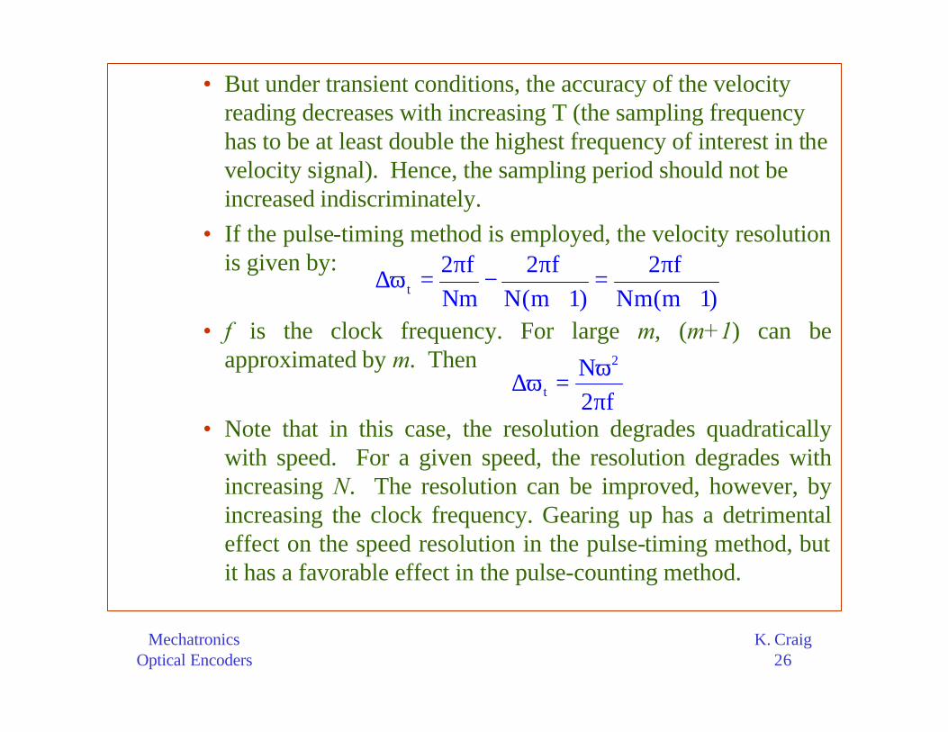
• But under transient conditions, the accuracy of the velocity reading decreases with increasing T (the sampling frequency has to be at least double the highest frequency of interest in the velocity signal). Hence, the sampling period should not be increased indiscriminately.
• If the pulse-timing method is employed, the velocity resolution is given by:
• f is the clock frequency. For large m, (m+1) can be approximated by m. Then
• Note that in this case, the resolution degrades quadratically with speed. For a given speed, the resolution degrades with increasing N. The resolution can be improved, however, by increasing the clock frequency. Gearing up has a detrimental effect on the speed resolution in the pulse-timing method, but it has a favorable effect in the pulse-counting method.
t
2 f 2 f 2 f
Nm N(m 1) Nm(m 1)
π π π∆ω = − =
+ +
2
t
N
2 f
ω∆ω =
π
MechatronicsOptical Encoders
K. Craig27
– In summary, the speed resolution of an incremental encoder depends on the following factors:
• number of windows N
• sampling period T
• clock frequency f
• speed ω• gear ratio
• Errors in shaft encoder readings can come from several factors:– Quantization error (due to digital word size limitations)
– Assembly error (eccentricity, etc.)
– Coupling error (gear backlash, belt slippage, loose fit, etc.)
MechatronicsOptical Encoders
K. Craig28
– Structural limitations (disk deformation and shaft deformation due to loading)
– Manufacturing tolerances (errors from inaccurately imprinted code patterns, inexact positioning of the pick-off sensors, limitations and irregularities in signal generation and sensing components, etc.)
• These factors can result in erroneous displacement and velocity readings and inexact direction detection.
• One form of error in an encoder reading is the hysteresis.
MechatronicsOptical Encoders
K. Craig29
– For a given position of the moving object, if the encoder reading depends on the direction of motion, the measurement has a hysteresis error.
– In that case, if the object rotates from position A to position B and back to position A, for example, the initial and final readings of the encoder will not match.
– The causes of hysteresis include backlash in gear couplings, loose fits, mechanical deformation in the code disk and shaft, delays in electronic circuitry (electrical time constants), and noisy pulse signals that make the detection of pulses (by level detection or edge detection) less accurate.
MechatronicsOptical Encoders
K. Craig30
Properties of the HP HEDS-5505-A14 Incremental Optical Encoder
Specification Values Supply Voltage 5 Volts Supply Current 40 mA
Resolution 500 pulses per revolution Resolution with quadrature 2000 pulses per revolution
Number of Channels 2 Index none
Maximum Velocity 30000 RPM Maximum Acceleration 250000 rad/sec2
MechatronicsOptical Encoders
K. Craig31
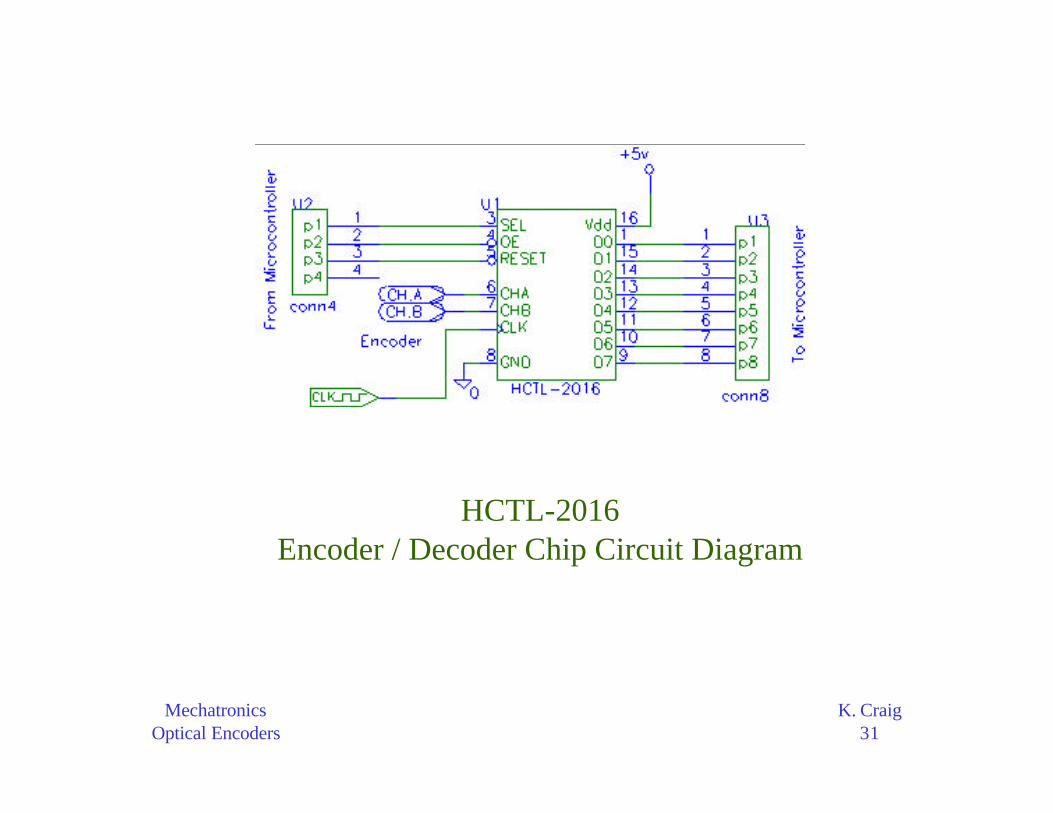
HCTL-2016Encoder / Decoder Chip Circuit Diagram
MechatronicsOptical Encoders
K. Craig32
• Encoder and Decoder Chip– The HCTL-20xx series of chips were specifically designed to resolve
the encoder signals and present the current position at any time. There are 3 forms of this chip:
• The cheapest, the HCTL-2000, has a 12-bit counter in which to keep track of the position. This means it can only count up to 4096 edges before rolling over.
• The HCTL-2016 has a 16-bit counter so it can count to 65535 before a roll over.
• The HCTL-2020 has an extra output which can be used to add on counters so that any number could be counted to before a roll over.
– The microcontroller must manipulate 3 signals in order to control the HCTL chip (the actual connector on the board has an additional position for reading the optional index pulse). The RESET pin simply sets the encoder count to 0. This is used for setting a ‘home’ position. The other two inputs from the microcontroller are SEL and OE. These signals are used to make the data bus (D0-D7) active and for figuring out which byte you want to see.
MechatronicsOptical Encoders
K. Craig33
– Since we have a 16-bit number for the position and only 8 pins to ‘display’ it on, we have to put the high byte on the pins and then the low byte on the pins. Multiply the high byte by 256 and addthe low byte and you have the proper count. The OE pin enables the outputs and the SEL pin chooses the high byte or low byte. When not reading the HCTL chip, both of these pins should remain high. So the sequence of events would be as shown in thetable below.
Sequence for Operating the HCTL Chip State OE SEL
Before a read takes place High High Prepare for High Byte High Low
Read High Byte Low Low Read Low Byte Low High
MechatronicsOptical Encoders
K. Craig34
– The HCTL chip also requires a clock signal. This square wave issimply there to allow the chip to process the encoder channels properly and to provide a way to help filter out noise. The clock is implemented with a high frequency oscillator. This component usually comes in a metal package and is very simple to use. It only requires 5 volts and ground and it will then generate the squarewaves indefinitely.
– The frequency is chosen based on the following:• The only requirement that the HCTL chip has is that the clock
frequency is at least 3 times larger than the highest frequency expected from either of the channels. This is only so that if the environment is noisy, it can filter out some of the noise by checking that the state of each channel remains the same for 3 cycles. If not, it will ignore the pulse.