Abstract: We present a polarimetric-based optical encoder for image encryption and verification. A system for generating random polarized vector keys based on a Mach-Zehnder configuration combined with translucent liquid crystal displays in each path of the interferometer is developed. Polarization information of the encrypted signal is retrieved by taking advantage of the information provided by the Stokes parameters. Moreover, photon-counting model is used in the encryption process which provides data sparseness and nonlinear transformation to enhance security. An authorized user with access to the polarization keys and the optical design variables can retrieve and validate the photon-counting plain-text. Optical experimental results demonstrate the feasibility of the encryption method.
1. O. Matoba, T. Nomura, E. Pérez-Cabré, M. S. Millan, and B. Javidi, “Optical Techniques for Information Security,” Proc. IEEE 97(6), 1128–1148 (2009).
2. A. Alfalou and C. Brosseau, “Optical image compression and encryption methods,” Adv. Opt. Photonics 1(3), 589–636 (2009).
3. W. Chen, B. Javidi, and X. Chen, “Advances in optical security systems,” Adv. Opt. Photonics 6(2), 120–155 (2014).
4. B. Javidi and J. L. Horner, “Optical pattern recognition for validation and security verification,” Opt. Eng. 33(6), 1752–1756 (1994).
5. P. Réfrégier and B. Javidi, “Optical image encryption based on input plane and Fourier plane random encoding,” Opt. Lett. 20(7), 767–769 (1995).
6. R. K. Wang, I. A. Watson, and C. Chatwin, “Random phase encoding for optical security,” Opt. Eng. 35(9), 2464–2469 (1996).
7. F. Goudail, F. Bollaro, B. Javidi, and P. Réfrégier, “Influence of a perturbation in a double phase-encoding system,” J. Opt. Soc. Am. A 15(10), 2629–2638 (1998).
8. Y. Li, K. Kreske, and J. Rosen, “Security and encryption optical systems based on a correlator with significant output images,” Appl. Opt. 39(29), 5295–5301 (2000).
9. A. Carnicer, M. Montes-Usategui, S. Arcos, and I. Juvells, “Vulnerability to chosen-cyphertext attacks of optical encryption schemes based on double random phase keys,” Opt. Lett. 30(13), 1644–1646 (2005).
10. Y. Frauel, A. Castro, T. J. Naughton, and B. Javidi, “Resistance of the double random phase encryption against various attacks,” Opt. Express 15(16), 10253–10265 (2007).
11. H. Tashima, M. Takeda, H. Suzuki, T. Obi, M. Yamaguchi, and N. Ohyama, “Known plaintext attack on double random phase encoding using fingerprint as key and a method for avoiding the attack,” Opt. Express 18(13), 13772–13781 (2010).
12. K. Nakano, M. Takeda, H. Suzuki, and M. Yamaguchi, “Evaluations of phase-only double random phase encoding based on key-space analysis,” Appl. Opt. 52(6), 1276–1283 (2013).
#226097 - $15.00 USD Received 31 Oct 2014; revised 15 Dec 2014; accepted 16 Dec 2014; published 12 Jan 2015 (C) 2015 OSA 26 Jan 2015 | Vol. 23, No. 2 | DOI:10.1364/OE.23.000655 | OPTICS EXPRESS 655
13. O. Matoba and B. Javidi, “Encrypted optical memory system using three-dimensional keys in the Fresnel domain,” Opt. Lett. 24(11), 762–764 (1999).
14. G. Unnikrishnan, J. Joseph, and K. Singh, “Optical encryption by double-random phase encoding in the fractional Fourier domain,” Opt. Lett. 25(12), 887–889 (2000).
15. P. Kumar, A. Kumar, J. Joseph, and K. Singh, “Impulse attack free double-random-phase encryption scheme with randomized lens-phase functions,” Opt. Lett. 34(3), 331–333 (2009).
16. X. Tan, O. Matoba, Y. Okada-Shudo, M. Ide, T. Shimura, and K. Kuroda, “Secure optical memory system with polarization encryption,” Appl. Opt. 40(14), 2310–2315 (2001).
17. O. Matoba and B. Javidi, “Secure holographic memory by double-random polarization encryption,” Appl. Opt. 43(14), 2915–2919 (2004).
18. J. F. Barrera, R. Henao, M. Tebaldi, R. Torroba, and N. Bolognini, “Multiplexing encrypted data by using polarized light,” Opt. Commun. 260(1), 109–112 (2006).
19. T. J. Naughton, B. M. Hennelly, and T. Dowling, “Introducing secure modes of operation for optical encryption,” J. Opt. Soc. Am. A 25(10), 2608–2617 (2008).
20. W. Chen and X. Chen, “Space-based optical image encryption,” Opt. Express 18(26), 27095–27104 (2010). 21. W. Chen, X. Chen, and C. J. R. Sheppard, “Optical image encryption based on diffractive imaging,” Opt. Lett.
35(22), 3817–3819 (2010). 22. F. Mosso, J. F. Barrera, M. Tebaldi, N. Bolognini, and R. Torroba, “All-optical encrypted movie,” Opt. Express
19(6), 5706–5712 (2011). 23. F. A. Sadjadi, “Passive three-dimensional imaging using polarimetric diversity,” Opt. Lett. 32(3), 229–231
(2007). 24. E. Pérez-Cabré, M. Cho, and B. Javidi, “Information authentication using photon-counting double-random-phase
encrypted images,” Opt. Lett. 36(1), 22–24 (2011). 25. Q. Zhan, “Cylindrical vector beams: from mathematical concepts to applications,” Adv. Opt. Photonics 1(1), 1–
57 (2009). 26. C. Maurer, A. Jesacher, S. Fürhapter, S. Bernet, and M. Ritsch-Marte, “Tailoring of arbitrary optical vector
beams,” New J. Phys. 9(3), 78 (2007). 27. X. L. Wang, J. Ding, W. J. Ni, C. S. Guo, and H. T. Wang, “Generation of arbitrary vector beams with a spatial
light modulator and a common path interferometric arrangement,” Opt. Lett. 32(24), 3549–3551 (2007). 28. I. Moreno, C. Iemmi, J. Campos, and M. J. Yzuel, “Jones matrix treatment for optical fourier processors with
structured polarization,” Opt. Express 19(5), 4583–4594 (2011). 29. F. Kenny, D. Lara, O. G. Rodríguez-Herrera, and C. Dainty, “Complete polarization and phase control for focus-
shaping in high-NA microscopy,” Opt. Express 20(13), 14015–14029 (2012). 30. W. Han, Y. Yang, W. Cheng, and Q. Zhan, “Vectorial optical field generator for the creation of arbitrarily
complex fields,” Opt. Express 21(18), 20692–20706 (2013). 31. I. Moreno, J. A. Davis, D. M. Cottrell, and R. Donoso, “Encoding high-order cylindrically polarized light
beams,” Appl. Opt. 53(24), 5493–5501 (2014). 32. D. Maluenda, I. Juvells, R. Martínez-Herrero, and A. Carnicer, “Reconfigurable beams with arbitrary
polarization and shape distributions at a given plane,” Opt. Express 21(5), 5432–5439 (2013). 33. D. Maluenda, R. Martínez-Herrero, I. Juvells, and A. Carnicer, “Synthesis of highly focused fields with circular
polarization at any transverse plane,” Opt. Express 22(6), 6859–6867 (2014). 34. M. Born and E. Wolf, Principles of Optics: Electromagnetic Theory of Propagation, Interference and
Diffraction of Light (Cambridge University, 1999). 35. J. W. Goodman, Statistical Optics (John Wiley & Sons, 1985). 36. G. M. Morris, “Image correlation at low light levels: a computer simulation,” Appl. Opt. 23(18), 3152–3159
(1984). 37. B. Javidi, “Nonlinear joint power spectrum based optical correlation,” Appl. Opt. 28(12), 2358–2367 (1989). 38. A. Markman, B. Javidi, and M. Tehranipoor, “Photon-counting security tagging and verification using optically
encoded QR codes,” IEEE Photon. J. 6, 6800609 (2013). 39. A. Carnicer, A. Hassanfiroozi, P. Latorre-Carmona, Y. P. Huang, and B. Javidi, “Security Authentication using
Phase-Encoded Nanoparticle Structures and Polarized Light,” Opt. Lett. doc. ID 225126 (posted 26 November 2014, in press).
40. E. Tajahuerce and B. Javidi, “Encrypting three-dimensional information with digital holography,” Appl. Opt. 39(35), 6595–6601 (2000).
1. Introduction
In recent years, optical security and encryption methods [1–16] have attracted the interest of many authors. In particular, double random phase-masks encryption (DRPE) is an effective method which is very suitable for encoding images that can be easily implemented in practice using a 4f system [3–8]. By means of this technique it is possible to encrypt a signal in such a way that becomes very difficult to be retrieved by an unauthorized user. Only those who have access to the phase mask in the Fourier plane can access the original signal. There are many variations of this technique which have been introduced by various authors some of which are
#226097 - $15.00 USD Received 31 Oct 2014; revised 15 Dec 2014; accepted 16 Dec 2014; published 12 Jan 2015 (C) 2015 OSA 26 Jan 2015 | Vol. 23, No. 2 | DOI:10.1364/OE.23.000655 | OPTICS EXPRESS 656
listed in [1–22]. Some authors have pointed out vulnerabilities of DRPE when facing specifically designed attacks [9–13], but security can be enhanced by increasing the number of degrees of freedom of this approach; for instance, changing the position of the phase masks in the optical setup [13,14]. Also, using randomized lens-phase functions can improve resistance against attack [15]. Another alternative is to use key masks that change the polarization direction and the phase difference between the electric field components [16–18]. Polarization has also been suggested as a method for extracting information from a scene [23]. Other methods to improve security have been proposed such as cryptographic blocks [19], a combination of real and virtual optics methods [20–22] or recording the encrypted distribution in low illumination conditions [24] using photon counting. Recording photon starved distributions is a highly nonlinear process in which only a few pixels of the encoded signal are recorded so that the corresponding decrypted image becomes very sparse and it does not reveal the original content. However, this distribution contains enough information to enable its validation when compared with the original image [24].
Interest in beams with non-uniform polarization patterns has increased significantly due to their special properties compared to homogeneously polarized beams, which can enhance the functionality of optical systems [25]. In particular, several methods based on interferometric configurations and liquid crystal displays have been suggested [26–31]. Recently, we reported a method for generating beams with arbitrary polarization based on a Mach-Zehnder setup combined with a translucent SLM in each path of the interferometer. The transverse components of the incident light beam are processed independently and modified by means of specifically designed holograms, recombined and imaged on a CCD camera. Our approach allows us to encode any polarization state at each point of the wave-front and the amplitude may also be modeled so as to obtain a particular shape in a given plane [32,33].
Random polarization distributions can be understood as encryption keys. In this paper, we describe an optical encryption processor based on a non-uniform arbitrary polarization setup. Moreover, security can be enhanced by recording the encrypted polarized signal under low-light illumination conditions using the photon-counting model. Our objective is to develop a Fresnel-like polarization encoder able to encrypt signals taking advantage of the information provided by the Stokes parameters. The encryption system is optically implemented whereas the decryption procedure is carried out numerically. The experiment demonstrates the feasibility of using this system as a polarimetric photon counting optical encoder for security applications.
Accordingly, the paper is organized as follows: in section 2, we describe the optical setup for generating wave-fronts with arbitrary polarization states and how this system can be used for optical encryption proposes. In section 3 we illustrate the proposed procedure by means of a set of numerical calculations whereas an experimental implementation of the system is presented in section 4. Finally, the main conclusions are summarized in section 5.
2. Polarization-based setup for optical encryption
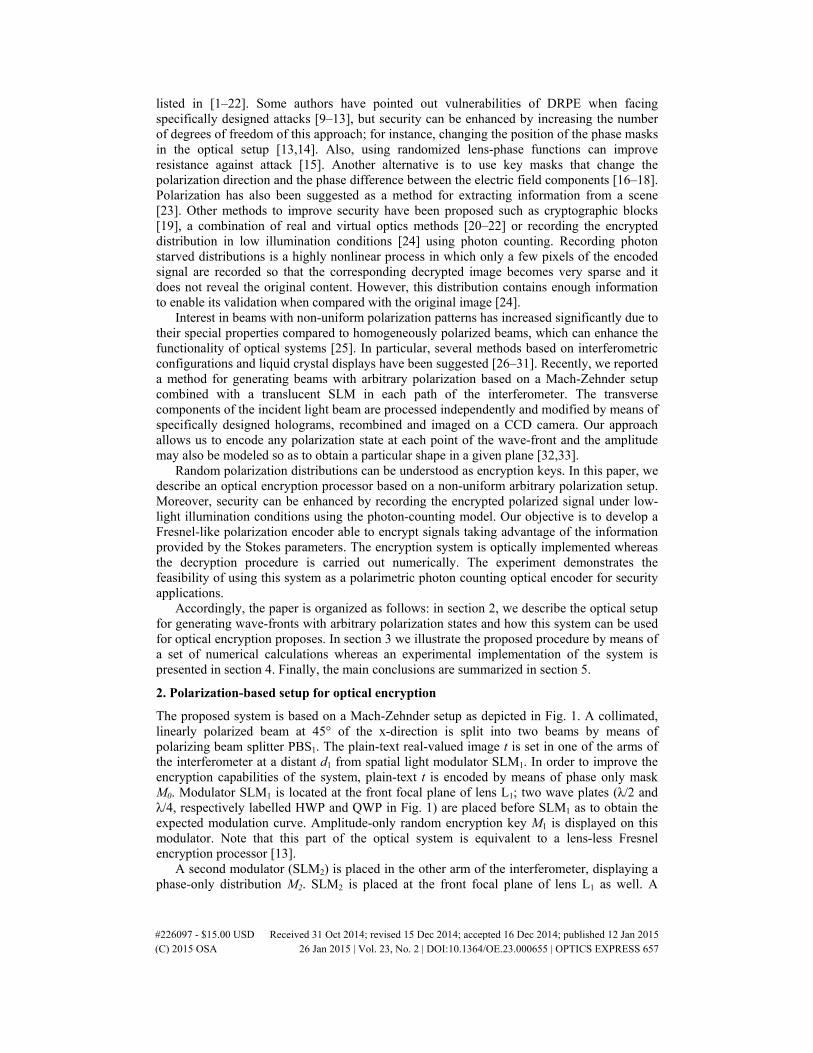
The proposed system is based on a Mach-Zehnder setup as depicted in Fig. 1. A collimated, linearly polarized beam at 45° of the x-direction is split into two beams by means of polarizing beam splitter PBS1. The plain-text real-valued image t is set in one of the arms of the interferometer at a distant d1 from spatial light modulator SLM1. In order to improve the encryption capabilities of the system, plain-text t is encoded by means of phase only mask M0. Modulator SLM1 is located at the front focal plane of lens L1; two wave plates (λ/2 and λ/4, respectively labelled HWP and QWP in Fig. 1) are placed before SLM1 as to obtain the expected modulation curve. Amplitude-only random encryption key M1 is displayed on this modulator. Note that this part of the optical system is equivalent to a lens-less Fresnel encryption processor [13].
A second modulator (SLM2) is placed in the other arm of the interferometer, displaying a phase-only distribution M2. SLM2 is placed at the front focal plane of lens L1 as well. A
#226097 - $15.00 USD Received 31 Oct 2014; revised 15 Dec 2014; accepted 16 Dec 2014; published 12 Jan 2015 (C) 2015 OSA 26 Jan 2015 | Vol. 23, No. 2 | DOI:10.1364/OE.23.000655 | OPTICS EXPRESS 657
neutral density filter controls the amount of light reaching this modulator. The information propagated through the two arms of the interferometer is recombined by means of PBS2. Since the modulators used are pixelated displays, a spatial filter is used for removing high order diffracted terms. Then, the light passes through a 4f imaging system; note that f1 and f2 are selected in such a way that the area of the CCD matches the size of SLM1 and SLM2. Finally, the encrypted signal is recorded by the CCD placed at a distance d2 from the back focal plane of lens L2. Accordingly, the vector cypher-text T is described as
[ ] [ ]
( )( ) ( )( )1 0 1 2 2 2
0 0 2 2
Pr Pr , , Pr ,
exp , exp , ,
x x y y x yT T M t M d d M d
M i x y M C i x yφ φ
= + = + = =
T e e e e (1)
where φ0, φ2 are uniformly distributed random variables in the interval [-π, π] and C is a constant related with the amount of light reaching SLM2. Distribution M1 is an amplitude encryption key in the range [ε,1] with ε >0, Pr[ ] stands for the propagation operator in Fresnel diffraction conditions; and vectors ex and ey are unit vectors in the x- and y- directions. Tx = |Tx| exp(iτx) and Ty = |Ty| exp(iτy) are the propagated fields in the first and second arms of the interferometer respectively. Note that since Tx and Ty are orthogonal complex valued distributions, the wave-front T is non-uniformly polarized. Moreover, no interference has to be detected at the CCD plane due to the orthogonality of Tx and Ty.
PBS1
PBS2
Mirror 1
Mirror 2
L1
L2SLM
2
SLM1QWP
Spatial filter
f1
Linearly polarizedlight (45º)
f1
f2
f2
Cypher-text T
LP/QWPPlain-text t
PC cypher-text Tph
d1 d
2
HWP
QWPHWP
Mask M0
Neutral density filter
CCD
Fig. 1. sketch of the optical setup.
Taking into account the vector character of T it is possible to extract amplitude and phase information using polarimetric techniques. Polarization analysis is carried out by placing a linear polarizer (LP) and a quarter-wave plate (QWP) when required in front of the CCD camera. Stokes images provide a complete description of the state of polarization in each point of the wave-front. A set of six polarimetric images (I(0°, 0), I(90°, 0), I(45°, 0), I(135°, 0), I(45°, π/2) and I(135°, π/2)) have to be recorded for calculating the four Stokes distributions (S0, S1, S2, S3) [34]:
0
1
2
3
(0 , 0) (90 , 0)
(0 , 0) (90 , 0)
(45 , 0) (135 , 0)
(45 , / 2) (135 , / 2).
S I I
S I I
S I I
S I Iπ π
= ° + °= ° − °= ° − °= ° − °
(2)
I(α, 0) stands for the recorded intensity when the linear polarizer is set at an angle α with respect to the x direction whereas I(α, π/2) is the image recorded when a quarter wave-plate is used in addition to the polarizer. The Stokes parameters associated to vector cypher-text T are used to recover amplitudes |Tx| and |Ty|, and the phase difference τy -τx. The formulae that relate the polarization ellipse parameters with the Stokes vector (S0, S1, S2, S3) are:
#226097 - $15.00 USD Received 31 Oct 2014; revised 15 Dec 2014; accepted 16 Dec 2014; published 12 Jan 2015 (C) 2015 OSA 26 Jan 2015 | Vol. 23, No. 2 | DOI:10.1364/OE.23.000655 | OPTICS EXPRESS 658
( )( )
22
0
22
1
2
3
2 cos
2 sin
x y
x y
x y y x
x y y x
S T T
S T T
S T T
S T T
τ τ
τ τ
= +
= −
= −
= −
(3)
or equivalently,
( )0 1 0 1 3
2
tan .2 2x y y x
S S S S ST T
Sτ τ+ −
= = − = (4)
After encryption, encoded distribution |Tx| exp(i(τy -τx)) is sent through a secure channel. The original plain-text t can be retrieved if and only if keys M1 and M2, and distances d1 and d2 are known. Notice that M1
−1 is well posed since M1 ≠ 0 at any point thus inversion is possible:
[ ]
( )
3 32 2
2 2
12 1 1
arc tan arg Pr , arc tan
= Pr Pr exp , , - .
x y
x x
S SM d
S S
t T i d M d
τ τ
τ −
= − = −
−
(5)
If a system works in low light illumination conditions, irradiance is recorded according to the photon-counting model. It is assumed that, in these conditions the image is statistically modeled by the Poisson distribution [35]. According to this law, the probability that no photon reaches pixel (xi,yi) is
( )( ) ( )( )0; , exp , ,i i p i iP x y n x y= − (6)
where np(xi,yi), is the normalized irradiance at pixel (xi, yi):
( ) ( )
( )
2
,2
, 1
,, .
,
p x i i
p i i N M
x i ii j
N T x yn x y
T x y=
=
(7)
NP is the predetermined number of photon counts in the entire scene and NxM is the total number of pixels. The photon-counting version |Tx|
ph of irradiance |Tx| is obtained according to
( ) ( ) ( )( )0, if rand , P 0; ,,
1, otherwise
ph i i i ix i i
x y x yT x y
≤=
(8)
where rand(xi,yi) is a uniformly distributed random number within the range [0,1]. In order to enhance security, photon-counting cypher-text |Tx|
ph exp(i(τy -τx)) is transmitted instead of using |Tx| exp(i(τy -τx)). Following Eq. (5), an authorized user with access to keys M1 and M2, and distances d1 and d2 can retrieve the photon-counting plain-text tph:
[ ] 132 2 2 1 1
2
= Pr Pr exp arg Pr , arc tan , , - .phph
x
St T i M d d M d
S−
− −
(9)
Finally, to determine whether tph contains information related with plain text t or not, the non-linear cross-correlation tph⊗t is calculated:
#226097 - $15.00 USD Received 31 Oct 2014; revised 15 Dec 2014; accepted 16 Dec 2014; published 12 Jan 2015 (C) 2015 OSA 26 Jan 2015 | Vol. 23, No. 2 | DOI:10.1364/OE.23.000655 | OPTICS EXPRESS 659
[ ][ ]
*
11 1
FT FTFT .
FT FT
ph
phk lph
t tt t
t t
−− −
⊗ =
(10)
Indexes k and l are selected in such ways that provide a good discrimination capability with a high peak-to-correlation energy [24, 36, 37].
3. Numerical test
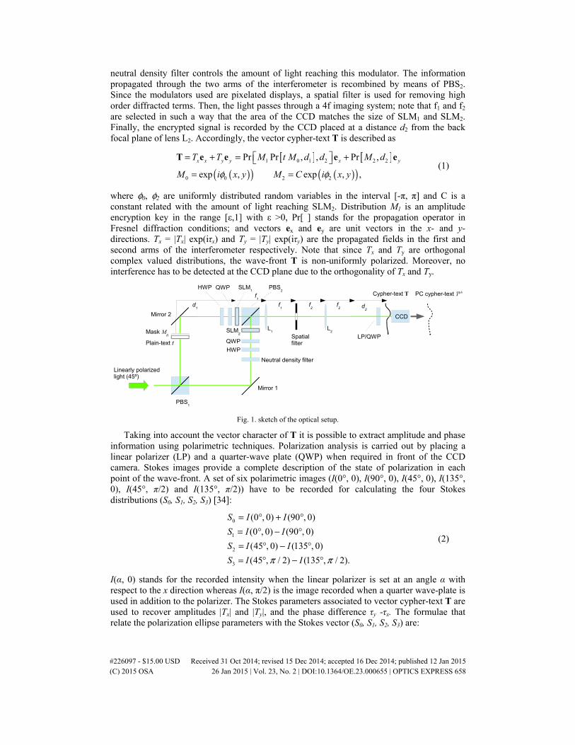
To illustrate the encryption process a digital simulation is presented. A 1951 USAF glass slide resolution test is used as a true plain-text t (Fig. 2(a)). For convenience we used the same resolution test but rotated 90° as the false-class image f (Fig. 2(b)). Inputs images t and f are phase encoded with M0. The simulation of the encryption and decryption processes is carried out using λ = 520 nm, d1 = 250 mm and d2 = 45 mm; and setting the size of the window to 10 mm. To prevent numerical problems in deriving the calculation of M1
−1, the minimum value of this key is set to ε = 0.2.
Fig. 2. (a) plain-text image t. (b) false-class plain text image f.
.
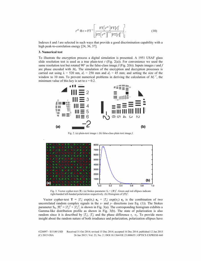
Fig. 3. Vector cypher-text (T): (a) Stokes parameter S0 = |(T)|2. Green and red ellipses indicate right-handed left-handed polarization respectively. (b) Histogram of |(T)|2.
Vector cypher-text T = |Tx| exp(iτx) ex + |Ty| exp(iτy) ey is the combination of two uncorrelated random complex signals in the x- and y- directions (see Eq. (1)). The Stokes parameter S0, |T|2 = |Tx|
2 + |Ty|2, is shown in Fig. 3(a). The corresponding histogram exhibits a
Gamma-like distribution profile as shown in Fig. 3(b). The state of polarization is also random since it is described by |Tx|, |Ty| and the phase difference τy -τx. To provide more insight about the random nature of both irradiance and polarization, polarization ellipses have
#226097 - $15.00 USD Received 31 Oct 2014; revised 15 Dec 2014; accepted 16 Dec 2014; published 12 Jan 2015 (C) 2015 OSA 26 Jan 2015 | Vol. 23, No. 2 | DOI:10.1364/OE.23.000655 | OPTICS EXPRESS 660
been calculated in some points of the recording plane. They appear superimposed in Fig. 3(a); green and red ellipses represent right-handed and left-handed polarization respectively
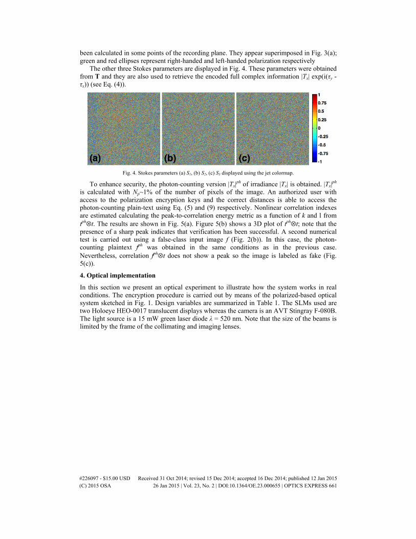
The other three Stokes parameters are displayed in Fig. 4. These parameters were obtained from T and they are also used to retrieve the encoded full complex information |Tx| exp(i(τy -τx)) (see Eq. (4)).
Fig. 4. Stokes parameters (a) S1, (b) S2, (c) S3 displayed using the jet colormap.
To enhance security, the photon-counting version |Tx|ph of irradiance |Tx| is obtained. |Tx|
ph is calculated with Np~1% of the number of pixels of the image. An authorized user with access to the polarization encryption keys and the correct distances is able to access the photon-counting plain-text using Eq. (5) and (9) respectively. Nonlinear correlation indexes are estimated calculating the peak-to-correlation energy metric as a function of k and l from tph⊗t. The results are shown in Fig. 5(a). Figure 5(b) shows a 3D plot of tph⊗t; note that the presence of a sharp peak indicates that verification has been successful. A second numerical test is carried out using a false-class input image f (Fig. 2(b)). In this case, the photon-counting plaintext fph was obtained in the same conditions as in the previous case. Nevertheless, correlation fph⊗t does not show a peak so the image is labeled as fake (Fig. 5(c)).
4. Optical implementation
In this section we present an optical experiment to illustrate how the system works in real conditions. The encryption procedure is carried out by means of the polarized-based optical system sketched in Fig. 1. Design variables are summarized in Table 1. The SLMs used are two Holoeye HEO-0017 translucent displays whereas the camera is an AVT Stingray F-080B. The light source is a 15 mW green laser diode λ = 520 nm. Note that the size of the beams is limited by the frame of the collimating and imaging lenses.
#226097 - $15.00 USD Received 31 Oct 2014; revised 15 Dec 2014; accepted 16 Dec 2014; published 12 Jan 2015 (C) 2015 OSA 26 Jan 2015 | Vol. 23, No. 2 | DOI:10.1364/OE.23.000655 | OPTICS EXPRESS 661
Fig. 5. (a) Nonlinear indexes estimation: Peak to correlation energy as a function of k and l. (b) true image (k = 0.1 and l = 0.7); (c) false image (k = 0.1 and l = 0.7).
Table 1. Values of the variables used in the optical implementation
Wavelength λ = 520 nmPropagation distances d1 = 250 mm and d2 = 45 mm Focal lengths f1 = 200 mm and f2 = 60 mm M1 minimum value ε = 0.2
SLM Pixel pitch 0.036 mmResolution (# of pixels) 1024 x 768 pixelsDiameter of the beam / encryption key 10 mmCCD Pixel pitch 0.00465 mmResolution (# of pixels) 1032 x 776 pixelsDiameter of the encrypted signal 3 mmNp (number of photons) Without phase mask M0 With phase mask M0
Np = 3000 (about 1%) Np = 9000 (about 3%)
In section 2, masks M1 and M2 were designed as amplitude-only and phase only
distributions. Nevertheless, in our experiment, the displays operate in phase mostly and high-contrast configurations (see Fig. 6); in both cases, a strong amplitude-phase coupling is obtained. For the case of display 1, the resulting M’1 mask is no longer real because the effective modulation curve encodes the mask. The same happens with mask M2 since key M’2 is also complex valued. Despite the fact that modulation encoding is a continuous and smooth deterministic procedure, this step introduces a nonlinear change on the encryption keys. Consequently, modulation curves have to be known in advantage in order to allow fully reconstruction of the plain-text.
#226097 - $15.00 USD Received 31 Oct 2014; revised 15 Dec 2014; accepted 16 Dec 2014; published 12 Jan 2015 (C) 2015 OSA 26 Jan 2015 | Vol. 23, No. 2 | DOI:10.1364/OE.23.000655 | OPTICS EXPRESS 662
Precise alignment between the corresponding pixels of the two SLMs is required in order to achieve a correct encryption signal. The tuning procedure is carried out by displaying the same test pattern on both SLMs (Fig. 7(a)) and subsequently imaging them on the CCD (Fig. 7(b)). Note that both images are polarized in orthogonal directions and no interference is detected. Then, one of the images is electronically shifted until both distributions coincide (Fig. 7(c)). If required, final fine tuning is accomplished by displacing slightly one of the displays using a XY motorized stage.
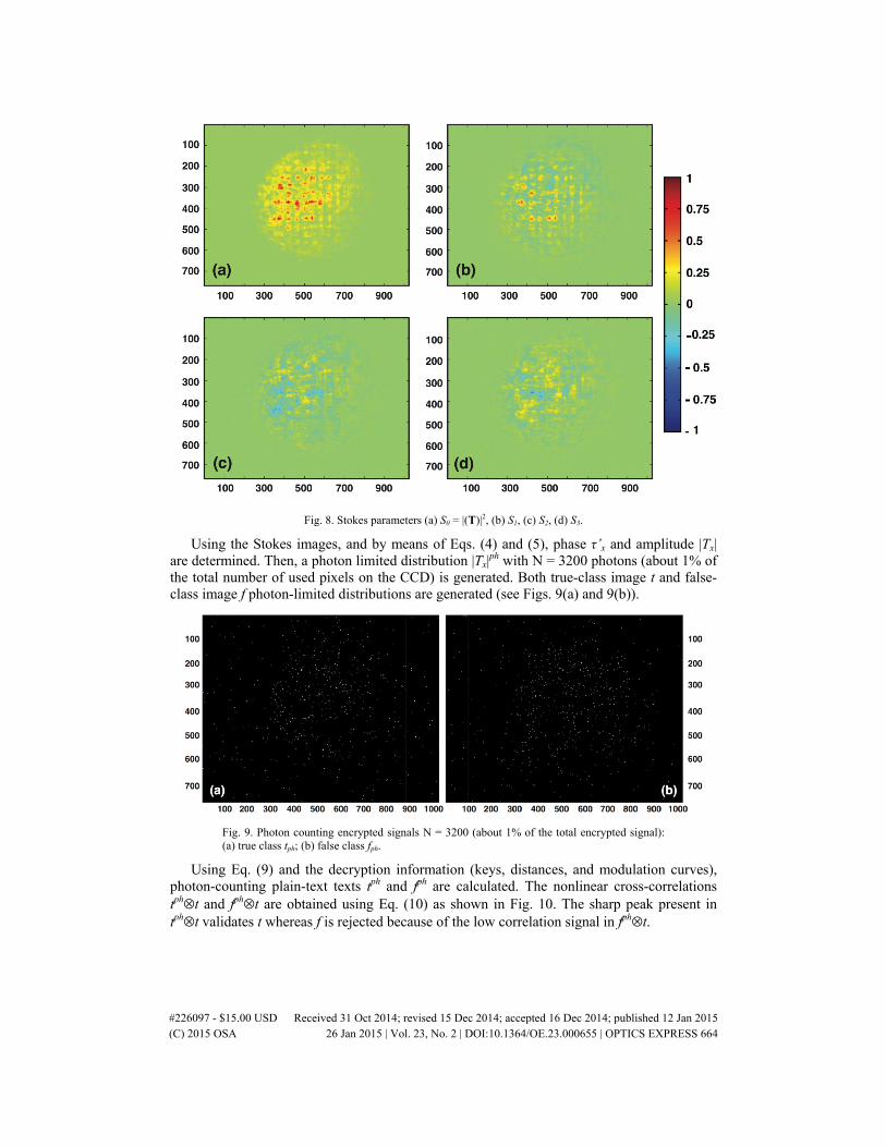
Then, images t and f (Figs. 2(a) and 2(b)) are encrypted. In this first test, but without loss of generality, the phase mask M0 is not used. For illustration purposes, the experimental Stokes parameters of the encrypted signal T for the true-class image t are shown in Figs. 8(a)-8(d).
#226097 - $15.00 USD Received 31 Oct 2014; revised 15 Dec 2014; accepted 16 Dec 2014; published 12 Jan 2015 (C) 2015 OSA 26 Jan 2015 | Vol. 23, No. 2 | DOI:10.1364/OE.23.000655 | OPTICS EXPRESS 663
Using the Stokes images, and by means of Eqs. (4) and (5), phase τ’x and amplitude |Tx| are determined. Then, a photon limited distribution |Tx|
ph with N = 3200 photons (about 1% of the total number of used pixels on the CCD) is generated. Both true-class image t and false-class image f photon-limited distributions are generated (see Figs. 9(a) and 9(b)).
Fig. 9. Photon counting encrypted signals N = 3200 (about 1% of the total encrypted signal): (a) true class tph; (b) false class fph.
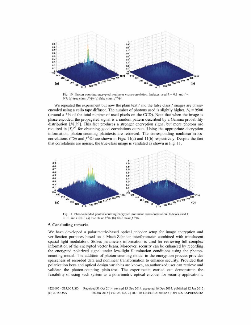
Using Eq. (9) and the decryption information (keys, distances, and modulation curves), photon-counting plain-text texts tph and fph are calculated. The nonlinear cross-correlations tph⊗t and fph⊗t are obtained using Eq. (10) as shown in Fig. 10. The sharp peak present in tph⊗t validates t whereas f is rejected because of the low correlation signal in fph⊗t.
#226097 - $15.00 USD Received 31 Oct 2014; revised 15 Dec 2014; accepted 16 Dec 2014; published 12 Jan 2015 (C) 2015 OSA 26 Jan 2015 | Vol. 23, No. 2 | DOI:10.1364/OE.23.000655 | OPTICS EXPRESS 664
Fig. 10. Photon counting encrypted nonlinear cross-correlation. Indexes used k = 0.1 and l = 0.7: (a) true class: tph⊗t (b) false class: f ph⊗t.
We repeated the experiment but now the plain text t and the false class f images are phase-encoded using a cello tape diffusor. The number of photons used is slightly higher, Np = 9500 (around a 3% of the total number of used pixels on the CCD). Note that when the image is phase encoded, the propagated signal is a random pattern described by a Gamma probability distribution [38,39]. This fact produces a stronger encryption signal but more photons are required in |Tx|
ph for obtaining good correlations outputs. Using the appropriate decryption information, photon-counting plaintexts are retrieved. The corresponding nonlinear cross-correlations tph⊗t and fph⊗t are shown in Figs. 11(a) and 11(b) respectively. Despite the fact that correlations are noisier, the true-class image is validated as shown in Fig. 11.
Fig. 11. Phase-encoded photon counting encrypted nonlinear cross-correlation. Indexes used k = 0.1 and l = 0.7: (a) true class: tph⊗t (b) false class: f ph⊗t.
5. Concluding remarks
We have developed a polarimetric-based optical encoder setup for image encryption and verification purposes based on a Mach-Zehnder interferometer combined with translucent spatial light modulators. Stokes parameters information is used for retrieving full complex information of the encrypted vector beam. Moreover, security can be enhanced by recording the encrypted polarized signal under low-light illumination conditions using the photon-counting model. The addition of photon-counting model in the encryption process provides sparseness of recorded data and nonlinear transformation to enhance security. Provided that polarization keys and optical design variables are known, an authorized user can retrieve and validate the photon-counting plain-text. The experiments carried out demonstrate the feasibility of using such system as a polarimetric optical encoder for security applications.
#226097 - $15.00 USD Received 31 Oct 2014; revised 15 Dec 2014; accepted 16 Dec 2014; published 12 Jan 2015 (C) 2015 OSA 26 Jan 2015 | Vol. 23, No. 2 | DOI:10.1364/OE.23.000655 | OPTICS EXPRESS 665
Since we are using an interferometric system in the implementation of encryption process, our approach can be extended to encrypting 3D objects [40].
Acknowledgments
This work has been partially supported by Ministerio de Ciencia e Innovación (Spain), project FIS2010-17543 and Ministerio de Economía y Competitividad projects FIS2013-46475. B. Javidi would like to gratefully acknowledge the University of Connecticut Center for Hardware Assurance, Security and Excellence (CHASE) for their support.
#226097 - $15.00 USD Received 31 Oct 2014; revised 15 Dec 2014; accepted 16 Dec 2014; published 12 Jan 2015 (C) 2015 OSA 26 Jan 2015 | Vol. 23, No. 2 | DOI:10.1364/OE.23.000655 | OPTICS EXPRESS 666