OPTICAL FIBERS FOR CHEMICAL SENSING AND BIOSENSING Vlastimil Matejec , Miroslav Chomat, Ivan Kasik, Ondrej Podrazky, Marie Pospisilova Institute of Photonics and Electronics AS CR, v.v.i., Chaberska 57, 182 51 Prague 8, Czech Republic Project BIO-OPT-XUV, Workshop W1, Kladno, October 3, 2011
Transcript
OPTICAL FIBERS FOR CHEMICAL SENSING AND
BIOSENSINGVlastimil Matejec,
Miroslav Chomat, Ivan Kasik, Ondrej Podrazky, Marie Pospisilova
Institute of Photonics and Electronics AS CR, v.v.i., Chaberska 57, 182 51 Prague 8, Czech Republic
Project BIO-OPT-XUV, Workshop W1, Kladno, October 3, 2011
OUTLINE• INTRODUCTION – Performance of IPE• EVANESCENT-WAVE FIBER-OPTIC
SENSORS- Ways for increasing the sensitivity
• FIBER-OPTIC TIPS- Detection in cells and small volumes
Single mode (SM) fibers1987 - : Special optical fibers for fiber lasers and
amplifiers and sensors
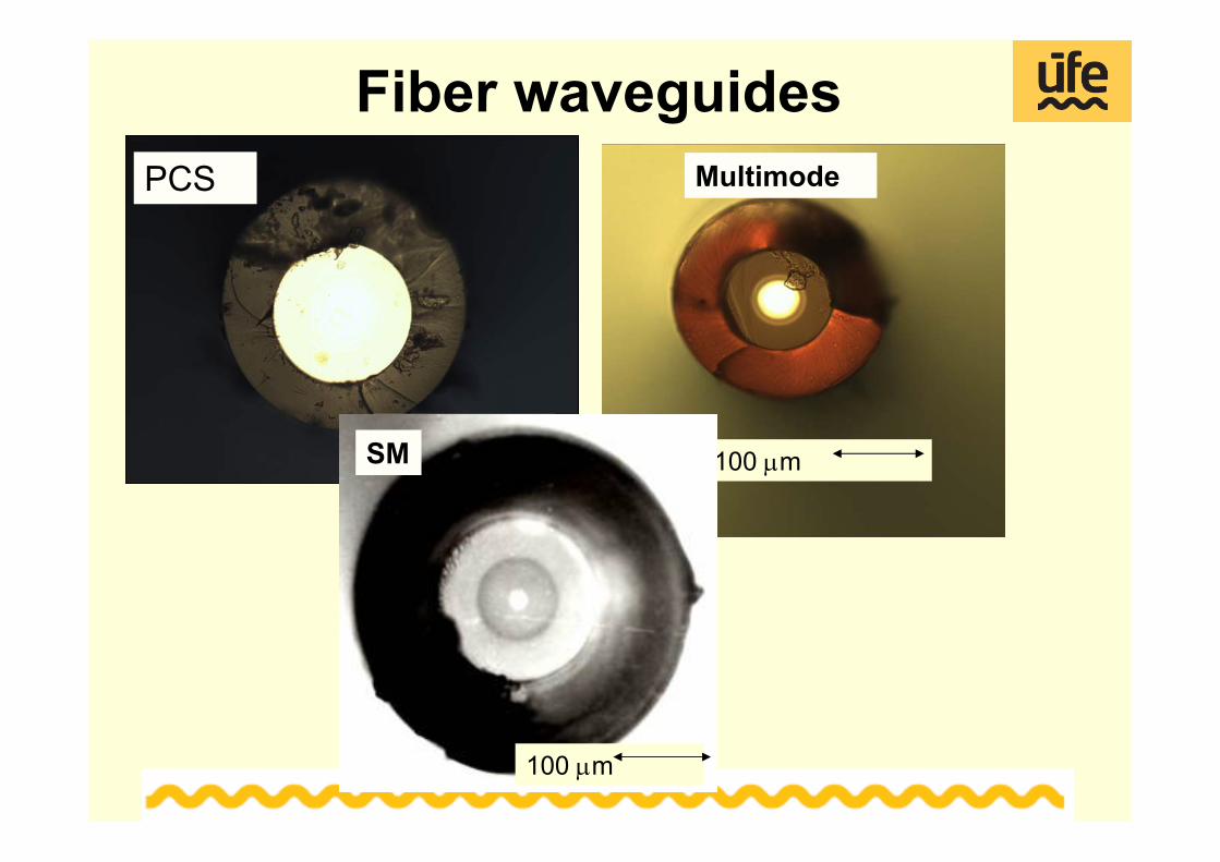
Fiber waveguides
100 μm
PCS
100 μm
Multimode
100 μm
SM
Attenuation of telecommunication fibers
800 1000 1200 1400 1600
1
10
100 10-10
0,01
0,1
0,316
0,794
PCS GI SM
Atte
nuat
ion
[dB
/km
]
Wavelength [nm]
Fully comparable with world producers
Fiber-Optic SensorsFiber-optic hardware for sensors employingEvanescent-wave detection principle
Fiber tipsMicrostructure fibers
Whispering Gallery Mode ResonatorsLong-period gratings in special fibers
Issue:How to control and increase the sensitivity of optical fibers to model chemicals or temperature?
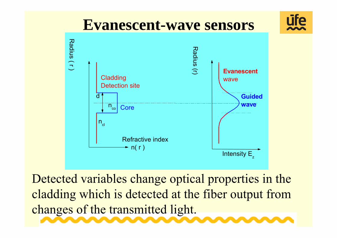
Detected variables change optical properties in the cladding which is detected at the fiber output from changes of the transmitted light.
Evanescent-wave sensors
d
ncl
nco
Guidedwave
Evanescentwave
Radius (r)
Intensity Ez
Radius ( r )
Refractive index n( r )
Core
CladdingDetection site
Advantages- Possibility to control the detection length and access of chemicals into the cladding .
- Detection principles based on refractometry, absorption and fluorescence spectroscopy could be employed
Limitations- Less than 1% of the optical power is transmitted in the cladding in standard fibers → low detection sensitivity.
- Evanescent waves penetrate into the cladding on micrometer distances.
? Ways for improving the detection sensitivity of standard optical fibers
Evanescent-wave sensors
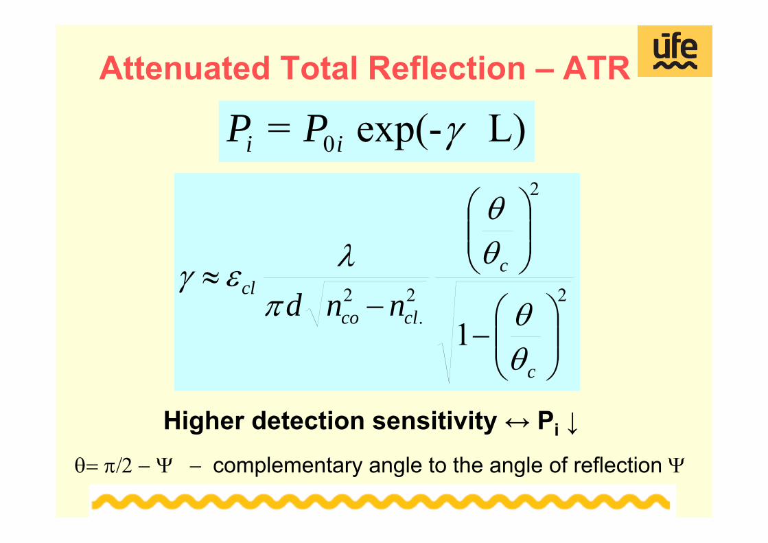
Attenuated Total Reflection – ATR
2
2
2.
2
1 ⎟⎟⎠
⎞⎜⎜⎝
⎛−
⎟⎟⎠
⎞⎜⎜⎝
⎛
−≈
c
c
clcocl
nnd
θθ
θθ
πλεγ
L) exp(- = 0 γii PP
θ= π/2 − Ψ − complementary angle to the angle of reflection Ψ
Higher detection sensitivity ↔ Pi ↓
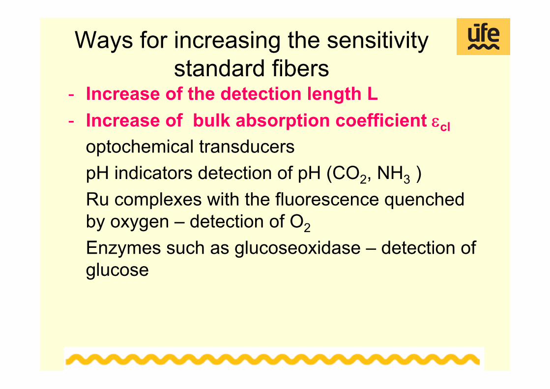
Ways for increasing the sensitivity standard fibers
- Increase of the detection length L - Increase of bulk absorption coefficient εcl
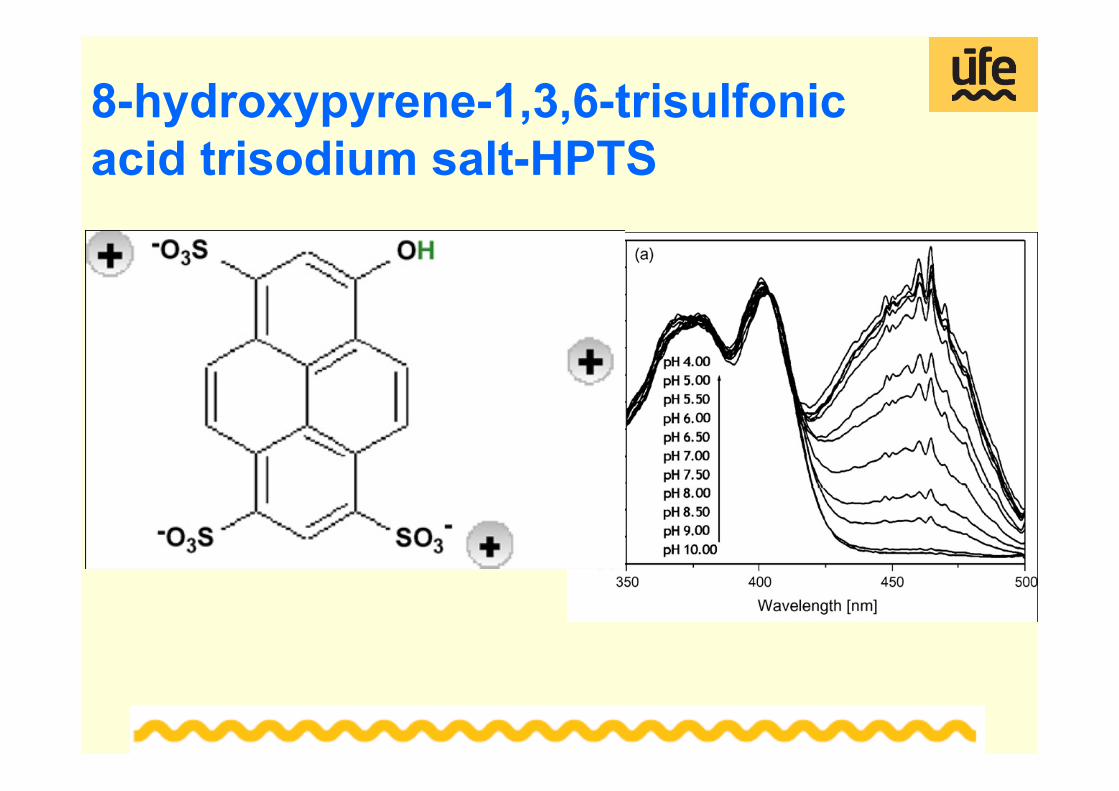
optochemical transducers pH indicators detection of pH (CO2, NH3 )Ru complexes with the fluorescence quenched by oxygen – detection of O2
Enzymes such as glucoseoxidase – detection of glucose
Ways for increasing the sensitivity- Materials of the core and cladding ncl →nco - PCG
fibers, detection membranes- Decrease of d - sectorial fibers,D-fibers
V. Matejec et al., Sens. Actuators B39 , 334 (1997)- Control of the reflection angle θ → θc
excitation by an inclined collimated beam, beveled fibersA. Abdelghani et al., Sens. Actuators B 44 , 495 (1997)inverted-graded fibersV. Matejec et al. Sens. Actuators B 51, 340 (1998)bent fibers (U fibers), coiled fibers V. Matejec et al., Sensor Lett. B 80, 132 (2001)
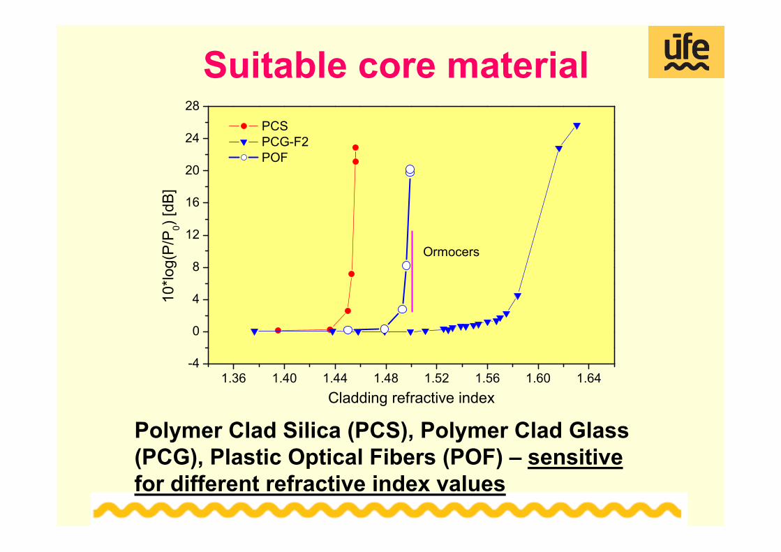
Suitable core material
1.36 1.40 1.44 1.48 1.52 1.56 1.60 1.64-4
0
4
8
12
16
20
24
28
PCS PCG-F2 POF
10*lo
g(P/
P 0) [dB
]
Cladding refractive index
Ormocers
Polymer Clad Silica (PCS), Polymer Clad Glass (PCG), Plastic Optical Fibers (POF) – sensitive for different refractive index values
Decrease of the core radius
D-fibers (Culshaw-UK-1985)Sectorial (s-) and D-fibers prepared by pulling from a properly ground and polished circular preform
Used mainly for gas and physical sensorsG. Stewart, W. Jin, B. Culshaw, Sens. Act. B 38, 42-47, 1997
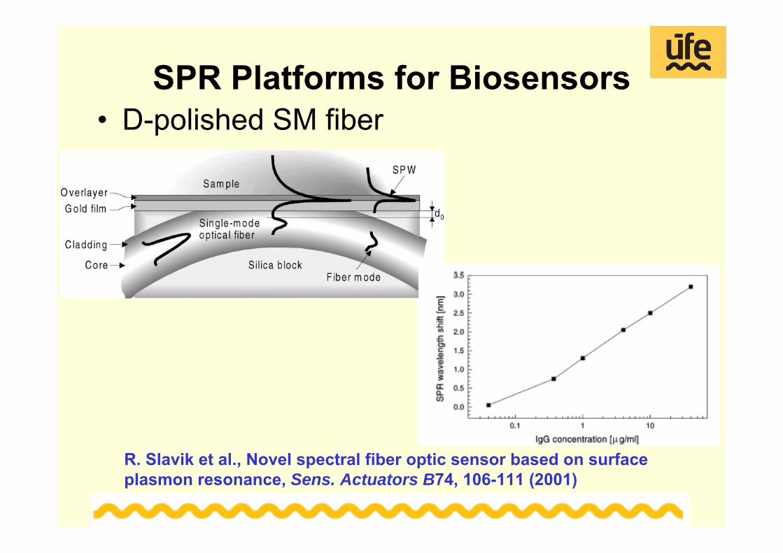
SPR Platforms for Biosensors• D-polished SM fiber
R. Slavik et al., Novel spectral fiber optic sensor based on surface plasmon resonance, Sens. Actuators B74, 106-111 (2001)
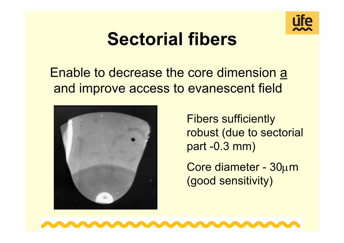
Sectorial fibers
Enable to decrease the core dimension a and improve access to evanescent field
Fibers sufficiently robust (due to sectorialpart -0.3 mm)
Core diameter - 30μm (good sensitivity)
Sectorial fibers – Spectral response
~5 times higher response than comparable PCS fibers
Si Detector
Laser diode - 630 nm
α
Motor
Gas in
Detection membrane
Solution in (out)
Cell
Gas out
Fiber
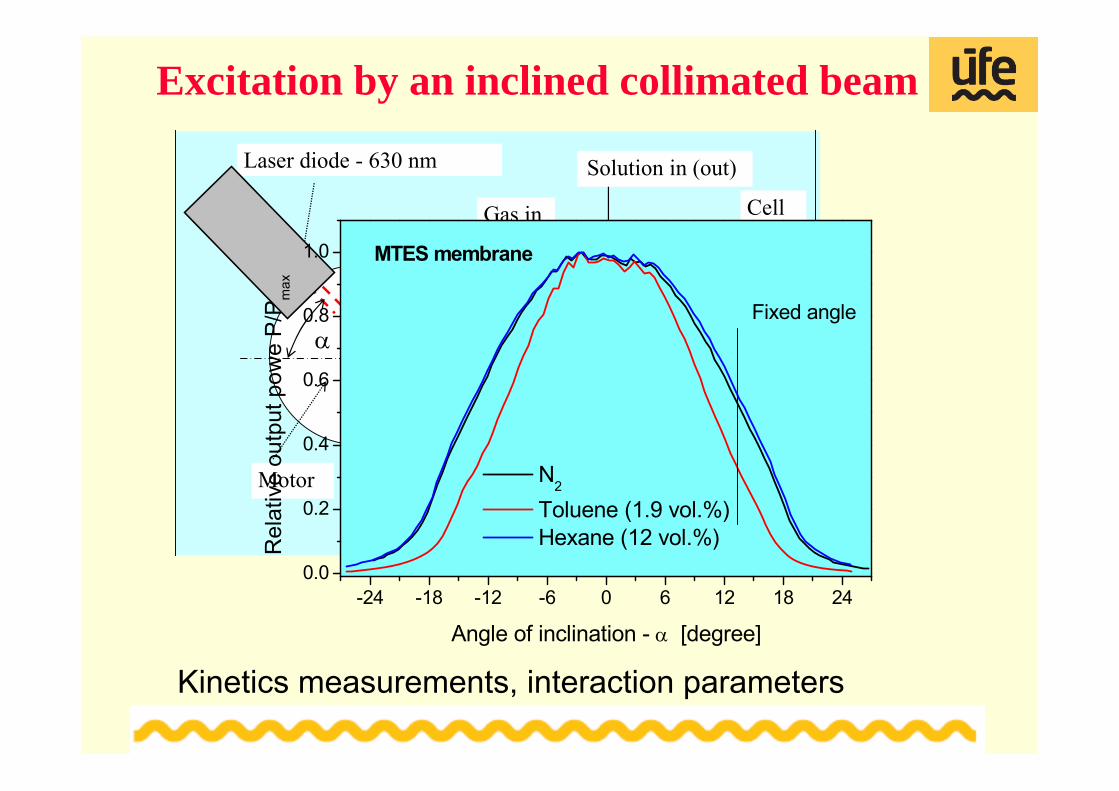
Excitation by an inclined collimated beam
Kinetics measurements, interaction parameters
-24 -18 -12 -6 0 6 12 18 240.0
0.2
0.4
0.6
0.8
1.0
Fixed angle
N2 Toluene (1.9 vol.%) Hexane (12 vol.%)R
elat
ive
outp
ut p
owe
P/P
max
Angle of inclination - α [degree]
MTES membrane
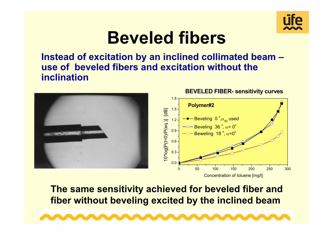
Beveled fibersInstead of excitation by an inclined collimated beam –use of beveled fibers and excitation without the inclination
0 50 100 150 200 250 3000.0
0.3
0.6
0.9
1.2
1.5
1.8
Polymer#2
BEVELED FIBER- sensitivity curves
Beveling 0 o,α50 used
Beveling 36 o, α= 0o
Beweling 18 o, α=0o
10*lo
g[P
(t=0)
/P(e
q.)]
[dB
]
Concentration of toluene [mg/l]
The same sensitivity achieved for beveled fiber and fiber without beveling excited by the inclined beam
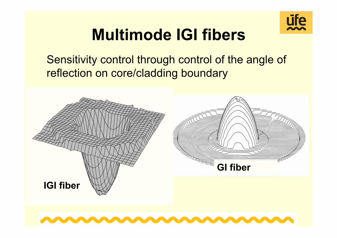
Multimode IGI fibersSensitivity control through control of the angle of reflection on core/cladding boundary
GI fiber
IGI fiber
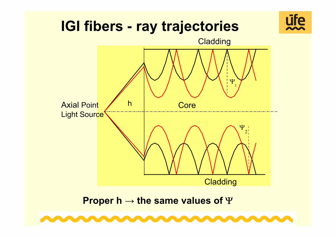
IGI fibers - ray trajectories
Cladding
Cladding
Axial PointLight Source
Core
Ψ2
Ψ1
h
Proper h → the same values of Ψ
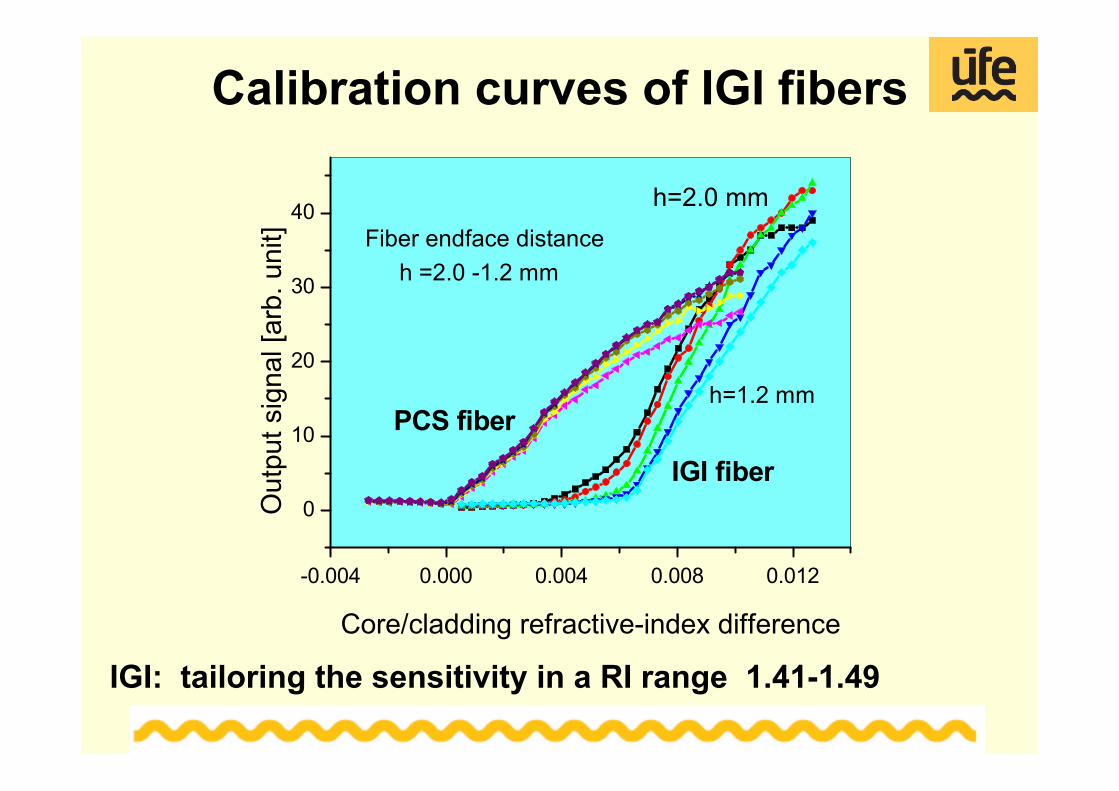
Calibration curves of IGI fibers
-0.004 0.000 0.004 0.008 0.012
0
10
20
30
40
IGI fiber
PCS fiber
h=2.0 mm
h=1.2 mm
h =2.0 -1.2 mmFiber endface distance
Out
put s
igna
l [ar
b. u
nit]
Core/cladding refractive-index difference
IGI: tailoring the sensitivity in a RI range 1.41-1.49
Bent fibers - U fibers
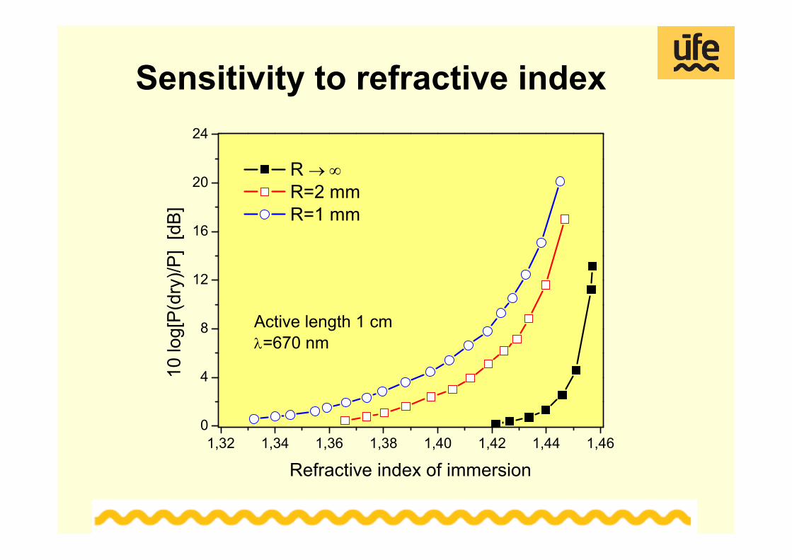
Sensitivity to refractive index
1,32 1,34 1,36 1,38 1,40 1,42 1,44 1,460
4
8
12
16
20
24
10 lo
g[P
(dry
)/P]
[dB
]
Refractive index of immersion
R → ∞ R=2 mm R=1 mm
Active length 1 cmλ=670 nm
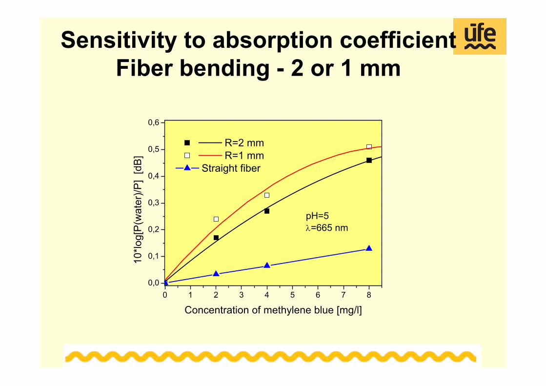
Sensitivity to absorption coefficientFiber bending - 2 or 1 mm
0 1 2 3 4 5 6 7 80,0
0,1
0,2
0,3
0,4
0,5
0,6
R=2 mm R=1 mm
Straight fiber
10*lo
g[P
(wat
er)/P
] [d
B]
Concentration of methylene blue [mg/l]
pH=5λ=665 nm
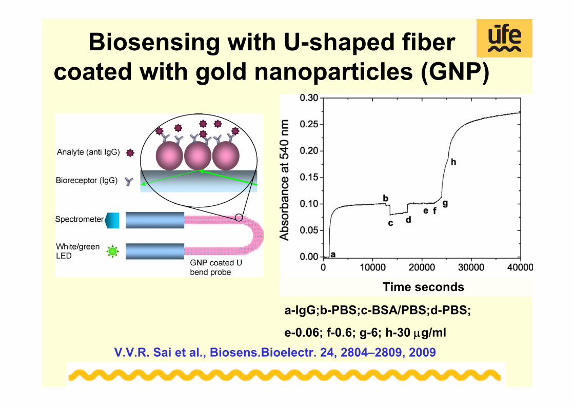
Biosensing with U-shaped fibercoated with gold nanoparticles (GNP)
V.V.R. Sai et al., Biosens.Bioelectr. 24, 2804–2809, 2009
Time seconds
a-IgG;b-PBS;c-BSA/PBS;d-PBS;
e-0.06; f-0.6; g-6; h-30 μg/ml
IPE Sensor of oxygen and glucose
LED light
PMT Detector
Main unit Communication A/D,
P
RS
Silica or PMMA
Sensing film is placed
Bent plastic fiber, detection membrane of ORMOCER®(n~1.5) with Ru complex and glucoseoxidase.
Detection based on monitoring oxygen consumption at the enzymatic reaction of glucose
Sensor of oxygen and glucose
0 100 200 300 400 500 600 700 800 900 1000 1100
0.66
0.68
0.70
0.72
0.74
0.76
0.78
0.80buffersolution removed
Air bubbled+1ml 0.1M glucose
+1ml 0.1M glucose
Rel
ativ
e flu
ores
cenc
e in
tens
ity
Time [s]
Time response Calibration
Detection limit 0.2 mM
0.0 0.5 1.0 1.5 2.00.0
0.1
0.2
0.3
0.4
0.5
10*lo
g[P
] [dB
]
Glucose concentration [mM]
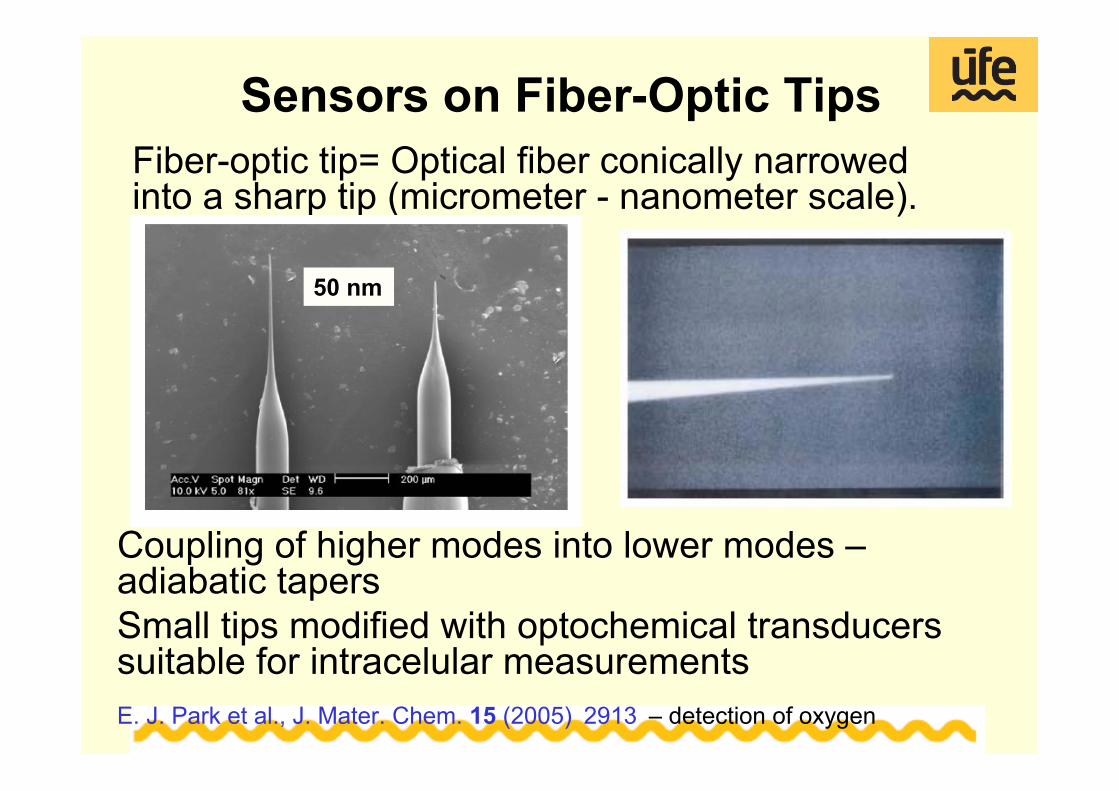
Sensors on Fiber-Optic TipsFiber-optic tip= Optical fiber conically narrowed into a sharp tip (micrometer - nanometer scale).
Coupling of higher modes into lower modes –adiabatic tapersSmall tips modified with optochemical transducers suitable for intracelular measurementsE. J. Park et al., J. Mater. Chem. 15 (2005) 2913 – detection of oxygen
50 nm
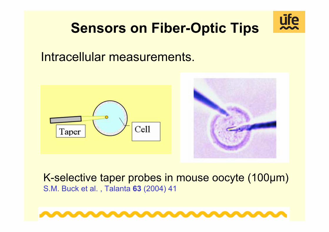
Sensors on Fiber-Optic Tips
Intracellular measurements.
K-selective taper probes in mouse oocyte (100μm)S.M. Buck et al. , Talanta 63 (2004) 41
Sensors on Fiber-Tapers
- R. Kopelman et al. (USA)E. J. Park et al., J. Mater. Chem. 15 (2005) 2913 – detection of oxygen M.R. Shortreed et al., Sens. Actuators B 38-39 (1997) 8 - detection of potassium
-T. Vo-Dingh et al., (USA)T. Vo-Dingh et al., J. Nanoparticle Research 2 (2000) 17-B.M. Cullum et al., Tibtech September 18 (2000) 388-reviewT. Vo-Dinh et al., Anal Bioanal Chem 382 (2005) 918 -reviewB. M. Cullum et al., Analytical Biochemistry 277 (2000) 25– benzo[a]pyrenetetrol in mammary carcinoma cells
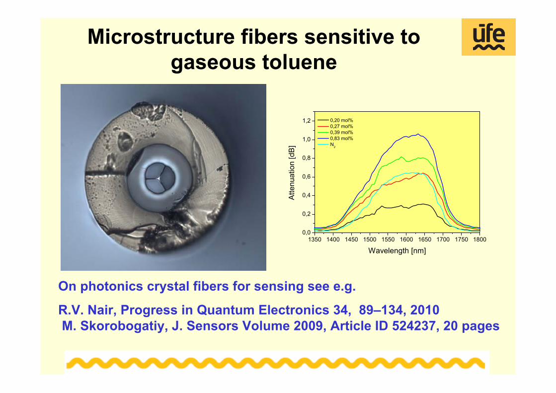
R.V. Nair, Progress in Quantum Electronics 34, 89–134, 2010M. Skorobogatiy, J. Sensors Volume 2009, Article ID 524237, 20 pages
WGM microresonators
Stems of microspheres fixedin silica capillaries for easily handling
K1-365 μmK2-330 μm
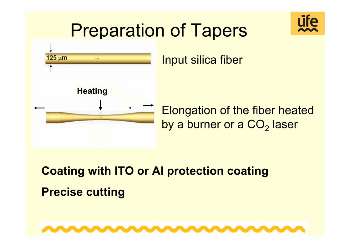
Heating a fiber tip with a burner
K3-67 μm
Heating a fiber with a CO2 laser
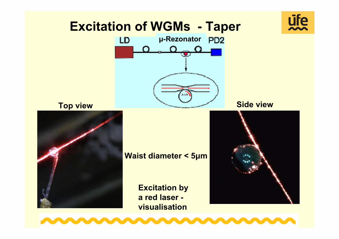
Excitation of WGMs - Taper
Top view Side view
Excitation by a red laser -visualisation
Waist diameter < 5μm
μ-Rezonator
WGM resonances-taperMicrosphere K1
Out
putV
olta
ge[m
V]
Time [ms]
---- Microresonator out contact
---- Microresonator in contact
Out of contact
In contact
Q ~ 106 detection length meters
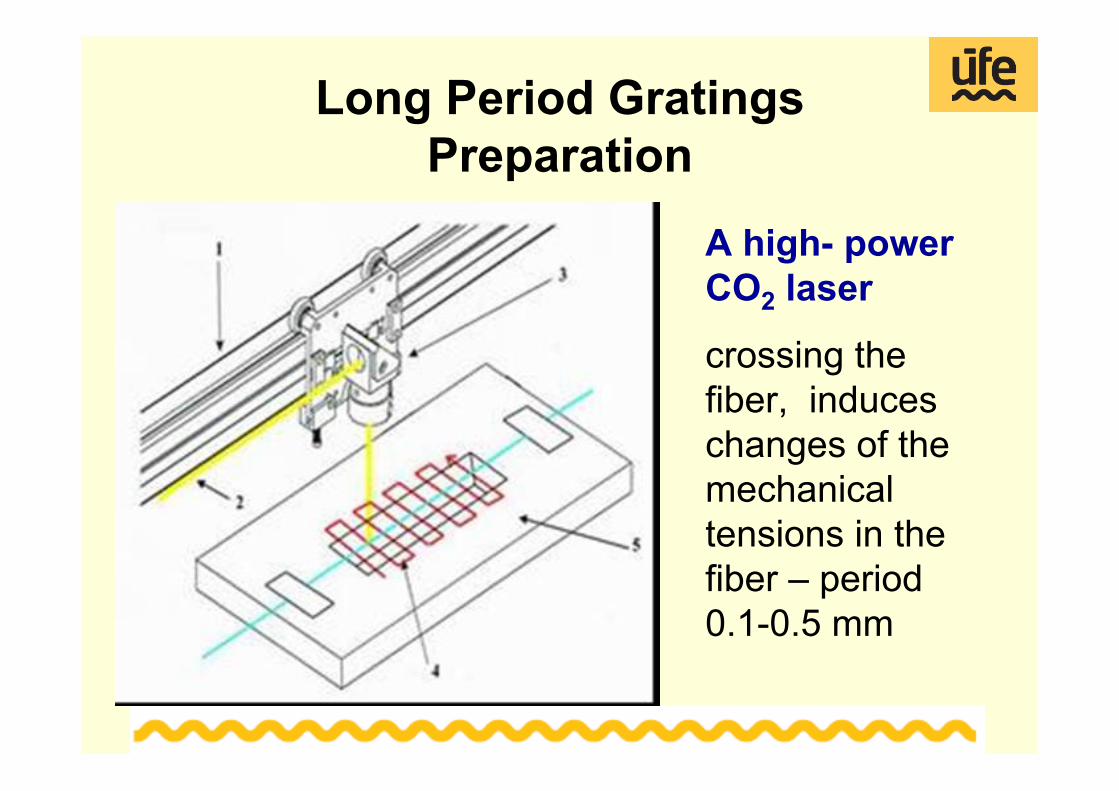
Long Period Gratings Preparation
A high- power CO2 laser
crossing the fiber, induces changes of the mechanical tensions in the fiber – period 0.1-0.5 mm
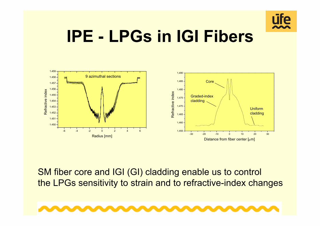
IPE - LPGs in IGI Fibers
-6 -4 -2 0 2 4 6
1.450
1.451
1.452
1.453
1.454
1.455
1.456
1.457
1.458
1.459
Ref
ract
ive
inde
x
Radius [mm]
9 azimuthal sections
SM fiber core and IGI (GI) cladding enable us to control the LPGs sensitivity to strain and to refractive-index changes
-30 -20 -10 0 10 20 301,455
1,460
1,465
1,470
1,475
1,480
1,485
1,490
Uniformcladding
Graded-indexcladding
Ref
ract
ive
inde
x
Distance from fiber center [μm]
Core
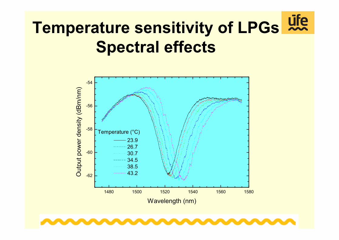
Temperature sensitivity of LPGsSpectral effects
1480 1500 1520 1540 1560 1580
-62
-60
-58
-56
-54
23.9 26.7 30.7 34.5 38.5 43.2
Out
put p
ower
den
sity
(dBm
/nm
)
Wavelength (nm)
Temperature (°C)
Conclusions1) IPE performance for the projectPreparation fiber-optic hardware for chemical sensors and biosensors applicable in medicine.Experience with the application of functional layers onto optical fibersExpertise with characterization of sensing modules 2) IPE offersFiber-optic elements for the application of optochemicaland biological transducers and testing their sensing performance- Bent fibers, beveled fibers, fiber tips, microresonatorsEducation of students