52
Operating manual NOSP15494-05 [07/2013] Optical Flame Detector MultiFlame DM-TV6 DM-TV6-T multi-spectrum IR DM-TV6-V combined UV/IR
Operating manual
NOSP15494-05 [07/2013]
Optical Flame Detector
MultiFlame DM-TV6
DM-TV6-T multi-spectrum IR
DM-TV6-V combined UV/IR
MultiFlame DM-TV6 Page 2 / 52 NOSP15494-05 [07/2013]
NoteNoteNoteNote
This manual must be carefully read by those who have or will have the responsibility for the operation or maintenance of this product. The product may not perform as designed if it is not used and maintained in accordance with the manufacturer’s instructions.
The warranties made by Simtronics with respect to the product are voided if the product is not used and maintained as described in this manual.
Please read the general warnings in chapter 9
© Simtronics SAS, all rights reserved.
MultiFlame DM-TV6 Page 3 / 52 NOSP15494-05 [07/2013]
1. Product Description .................................................................................................................5
1.1. Applications .......................................................................................................................5
1.2. DM-TV6-T: multi-spectrum IR .........................................................................................6
1.3. DM-TV6-V: combined UV and IR ......................................................................................6
1.4. Technical specifications ...................................................................................................7
1.5. Detection Cartridge ..........................................................................................................8
1.6. Optical self-test function ..................................................................................................8
1.7. Wireless Configuration Tool.............................................................................................8
1.8. Product Code.....................................................................................................................9
2. Technical Specifications ........................................................................................................11
3. Performances .........................................................................................................................13
3.1. Sensitivity ........................................................................................................................13
3.2. Field of View (Cone of Vision) .........................................................................................14
3.3. False alarm immunity (FM 3260) ...................................................................................15
4. Installation ..............................................................................................................................16
4.1. Location ...........................................................................................................................16
4.2. Mounting ..........................................................................................................................17
4.3. Electric Connection.........................................................................................................19
4.4. Detection cartridge .........................................................................................................25
5. Commissioning .......................................................................................................................27
5.1. Visual inspection .............................................................................................................27
5.2. Power-up .........................................................................................................................27
5.3. Operational tests.............................................................................................................27
6.1. Using the LT15 test lamp ...............................................................................................28
7. Operation.................................................................................................................................29
7.1. Environmental conditions ..............................................................................................29
7.2. Inhibition ..........................................................................................................................29
7.3. Signal current loop .........................................................................................................30
7.4. Power and fault indications............................................................................................30
7.5. Alarm indication (LED) ...................................................................................................31
7.6. Wireless communication tool TLU600 ..........................................................................32
7.7. Information menu [INFO] ...............................................................................................35
7.8. Adjustment menu [ADJT] ...............................................................................................36
7.9. The maintenance menu [MAIN] .....................................................................................38
8. HART communication.............................................................................................................39
9. Maintenance............................................................................................................................40
9.1. Periodic maintenance .....................................................................................................40
MultiFlame DM-TV6 Page 4 / 52 NOSP15494-05 [07/2013]
9.2. List of main faults ...........................................................................................................41
9.3. Replacing the cartridge ..................................................................................................41
9.4. Replacing the complete detector...................................................................................41
10. Warnings .............................................................................................................................42
10.1. Safety ...........................................................................................................................42
10.2. Ownership and confidentiality ....................................................................................42
11. Warranty ..............................................................................................................................43
12. Certifications and standards..............................................................................................44
12.1. Standards ....................................................................................................................44
12.2. Functional Safety (update pending) ...........................................................................44
12.3. Approvals .....................................................................................................................44
12.4. CE - DPC ......................................................................................................................44
12.5. Marking ........................................................................................................................45
13. Accessories and spareparts ..............................................................................................46
13.1. Accessories .................................................................................................................46
13.2. Spare parts ..................................................................................................................47
14. Conformity certificate.........................................................................................................48
15. Contact details ....................................................................................................................51
MultiFlame DM-TV6 Page 5 / 52 NOSP15494-05 [07/2013]
1. PRODUCT DESCRIPTION
MultiFlame DM-TV6 was designed to detect hydrocarbon fires, while minimizing false alarms.
This detector is equipped with an intelligent optical self-test. It is certified to be installed in SIL2 level system. It can be directly connected to a wide range of traditional or fire controllers and on Programmable Logic Controllers (PLC).
DM-TV6 can be fully configured using the portable communication terminal (TLU600),
providing flexibility to the user. Time delay, sensitivity and outputs configuration can be full set up via the TLU600, a hazardous area approved remote control. Optical and electronic parts, and outputs (current, relay…) of the detector can be controlled by the TLU.
The MultiFlame products family consists of two detector versions:
• DM-TV6-T multi-spectrum IR Flame detector
• DM-TV6-V combined UV and IR
The MultiFlame models are also available for use in an addressable network system with distributed intelligence, SYNTEL. This version is named DM-RV6-*. For more information, please refer to the Syntel module interface operating manual.
1.1. Applications
• Refineries
• Drilling and Production Platforms
• FPSO
• Fuel Loading Facilities
• Compressor Stations
• LNG/LPG Processing and Storage
• Gas Turbines
• Chemical Plants
• Aircraft Hangars
The sensitivity of flame detectors depends on many factors including, fuel type, fire size, atmospheric conditions (wind, rain, fog, etc...), the angle between the fire and detector as well as line of sight obstructions.
MultiFlame DM-TV6 Page 6 / 52 NOSP15494-05 [07/2013]
1.2. DM-TV6-T: multi-spectrum IR
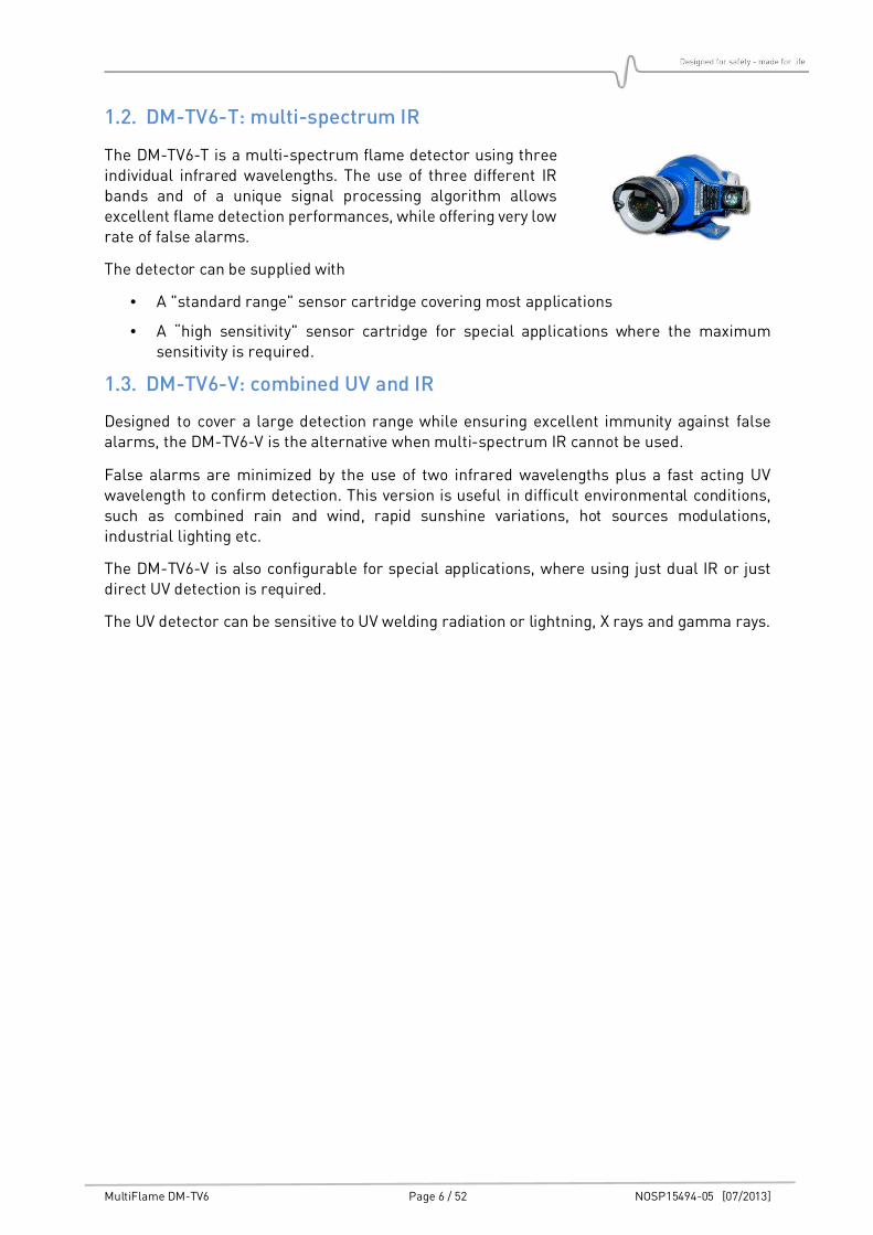
The DM-TV6-T is a multi-spectrum flame detector using three individual infrared wavelengths. The use of three different IR bands and of a unique signal processing algorithm allows excellent flame detection performances, while offering very low rate of false alarms.
The detector can be supplied with
• A "standard range" sensor cartridge covering most applications
• A “high sensitivity" sensor cartridge for special applications where the maximum sensitivity is required.
1.3. DM-TV6-V: combined UV and IR
Designed to cover a large detection range while ensuring excellent immunity against false alarms, the DM-TV6-V is the alternative when multi-spectrum IR cannot be used.
False alarms are minimized by the use of two infrared wavelengths plus a fast acting UV wavelength to confirm detection. This version is useful in difficult environmental conditions, such as combined rain and wind, rapid sunshine variations, hot sources modulations, industrial lighting etc.
The DM-TV6-V is also configurable for special applications, where using just dual IR or just direct UV detection is required.
The UV detector can be sensitive to UV welding radiation or lightning, X rays and gamma rays.
MultiFlame DM-TV6 Page 7 / 52 NOSP15494-05 [07/2013]
1.4. Technical specifications
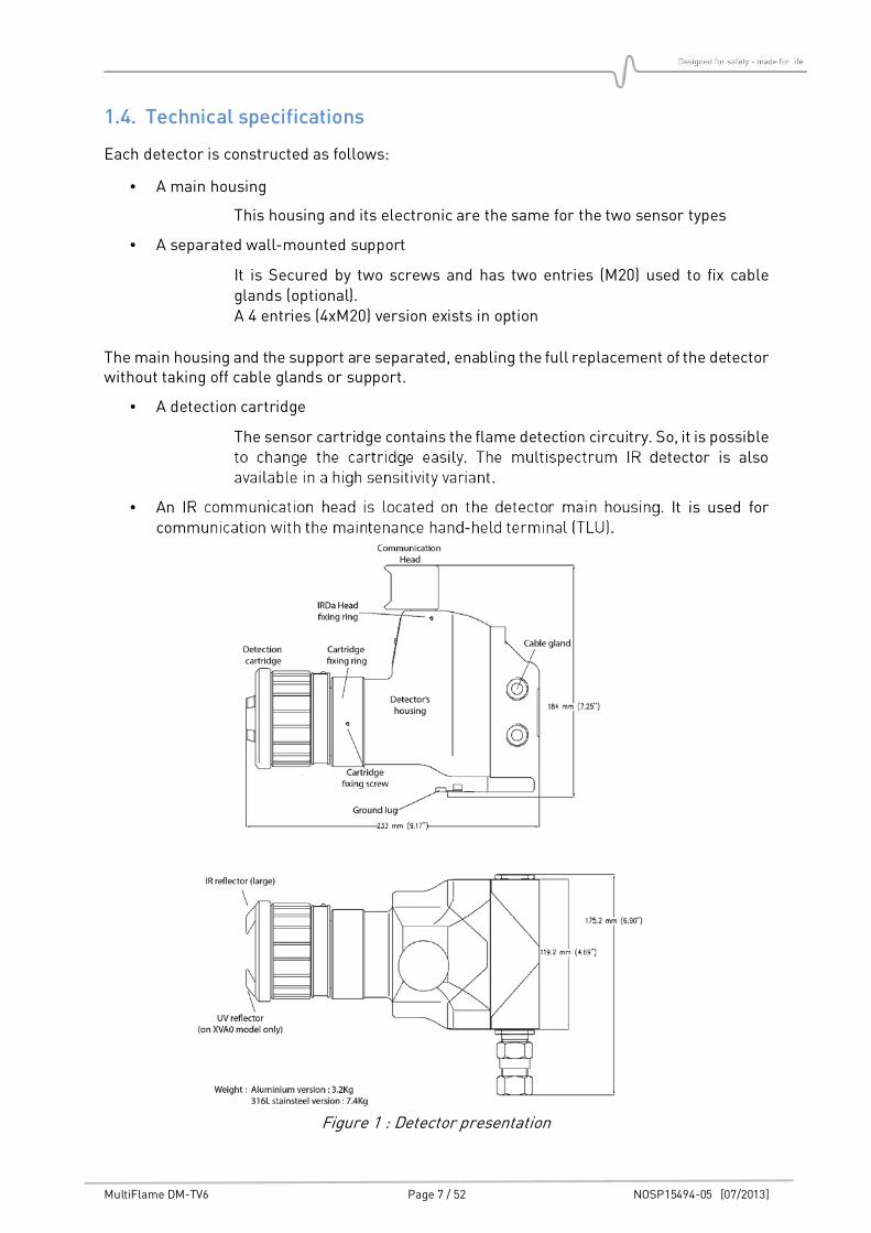
Each detector is constructed as follows:
• A main housing
This housing and its electronic are the same for the two sensor types
• A separated wall-mounted support
It is Secured by two screws and has two entries (M20) used to fix cable glands (optional). A 4 entries (4xM20) version exists in option
The main housing and the support are separated, enabling the full replacement of the detector without taking off cable glands or support.
• A detection cartridge
The sensor cartridge contains the flame detection circuitry. So, it is possible to change the cartridge easily. The multispectrum IR detector is also available in a high sensitivity variant.
• An IR communication head is located on the detector main housing. It is used for communication with the maintenance hand-held terminal (TLU).
Figure 1 : Detector presentation
MultiFlame DM-TV6 Page 8 / 52 NOSP15494-05 [07/2013]
1.5. Detection Cartridge
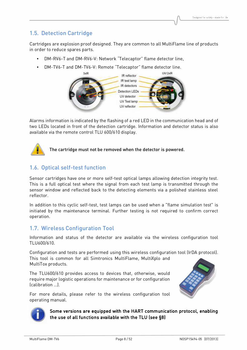
Cartridges are explosion proof designed. They are common to all MultiFlame line of products in order to reduce spares parts.
• DM-RV6-T and DM-RV6-V: Network “Telecaptor” flame detector line,
• DM-TV6-T and DM-TV6-V: Remote “Telecaptor” flame detector line.
Alarms information is indicated by the flashing of a red LED in the communication head and of two LEDs located in front of the detection cartridge. Information and detector status is also available via the remote control TLU 600/610 display.
The cartridge must not be removed when the detector is powered.
1.6. Optical self-test function
Sensor cartridges have one or more self-test optical lamps allowing detection integrity test. This is a full optical test where the signal from each test lamp is transmitted through the sensor window and reflected back to the detecting elements via a polished stainless steel reflector.
In addition to this cyclic self-test, test lamps can be used when a "flame simulation test" is
initiated by the maintenance terminal. Further testing is not required to confirm correct operation.
1.7. Wireless Configuration Tool
Information and status of the detector are available via the wireless configuration tool TLU600/610.
Configuration and tests are performed using this wireless configuration tool (IrDA protocol).
This tool is common for all Simtronics MultiFlame, MultiXplo and MultiTox products.
The TLU600/610 provides access to devices that, otherwise, would require major logistic operations for maintenance or for configuration (calibration …).
For more details, please refer to the wireless configuration tool operating manual.
Some versions are equipped with the HART communication protocol, enabling Some versions are equipped with the HART communication protocol, enabling Some versions are equipped with the HART communication protocol, enabling Some versions are equipped with the HART communication protocol, enabling
the use of all functions available with the use of all functions available with the use of all functions available with the use of all functions available with the TLU (see §the TLU (see §the TLU (see §the TLU (see §8888))))
MultiFlame DM-TV6 Page 9 / 52 NOSP15494-05 [07/2013]
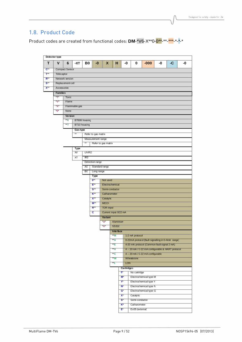
1.8. Product Code
Product codes are created from functional codes: DM-*V6-X**0-0**-**-***-*-*-*
Detector type
T V 6 -XT B0 -0 X H -0 0 -000 -0 -C -0
C** Compact Sensor
T** Télécaptor
R** Network version
S** Replacement cell
X** Accessories
Families
*T* Toxic
*V* Flame
*X* Flammable gas
*0* None
Version
**6 BT606 housing
**7 BT10 housing
Gas type
** Refer to gas matrix
Measurement range
** Refer to gas matrix
Type
XV UVIR2
XT IR3
Detection range
A0 Standard range
B0 Long range
Type
0** Not used
E** Electrochemical
S** Semi-conductor
K** Catharometer
X** Catalytic
M** MECH
R** TOR input
C Current input 0/22 mA
Variant
*A* Aluminium
*X* SS316
Interface
**M 1-2 mA protocol
**A 0-22mA protocol (fault signalling in 0-4mA range)
**E 4-20 mA protocol (Common fault signal 2 mA)
**H 4 – 20 mA / 0-22 mA configurable & HART protocol
**C 4 – 20 mA / 0-22 mA configurable
**W Wheatstone
**L LON
Cartridges
0* No cartridge
M* Electrochemical type M
Y* Electrochemical type Y
N* Electrochemical type N
G* Electrochemical type G
X* Catalytic
S* Semi-conductor
K* Catharometer
E* Ex05 (external)
MultiFlame DM-TV6 Page 10 / 52 NOSP15494-05 [07/2013]
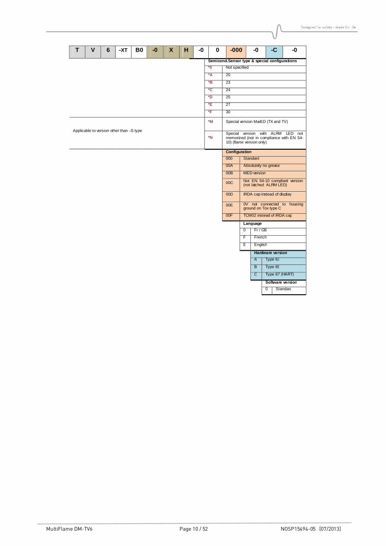
T V 6 -XT B0 -0 X H -0 0 -000 -0 -C -0
Semicond.Sensor type & special configurations
*0 Not specified
*A 20
*B 23
*C 24
*D 25
*E 27
*F 30
Applicable to version other than –S type
*M Special version MarED (TX and TV)
*N Special version with ALRM LED not memorized (not in compliance with EN 54-10) (flame version only)
Configuration
000 Standard
00A Absolutely no grease
00B MED version
00C Not EN 54-10 compliant version (not latched ALRM LED)
00D IRDA cap instead of display
00E 0V not connected to housing ground on Tox type C
00F TCM02 instead of IRDA cap
Language
0 Fr / GB
F French
E English
Hardware version
A Type 63
B Type 65
C Type 67 (HART)
Software version
0 Standard
MultiFlame DM-TV6 Page 11 / 52 NOSP15494-05 [07/2013]
2. TECHNICAL SPECIFICATIONS
GENERAL Type Optical flame detectors
DM-TV6-T Multi-spectrum Infrared
DM-TV6-V Combined IR and UV detection. Also configurable to single UV or dual IR for specific applications.
Start-up time 15 sec
Self-test Automatic periodic through the lens testing
Calibration Factory set, no field recalibration
OUTPUT SIGNAL 4-20mA loop signal Active type (source), max. load impedance 700Ω.
E-variant, "4-20mA" 4-20mA loop with a single fault level
- Normal 4 mA - Flame alarm 20 mA - Fault or inhibition 2 mA
A-variant, "0-22mA" 4-20mA loop with multiple fault levels, suitable for PLC’s and modern control systems.
- Normal 4 mA - Flame alarm 20 mA - Inhibition 3.4 mA
- Optical self-test fault 2.6 mA - HW/SW fault 2.0 mA
Relay output 2 x configurable relays max 1A / 30V, AC/DC
ELECTRICAL
Power supply 24VDC, (18 – 28 V DC versions DM-TV6)
(18 – 30 V DC versions DM-RV6)
Power consumption 70 mA normal; 155 mA during optical self-test
Connection 0.3 mm2 (22 AWG) - 1.5 mm2 (16 AWG)
MTBF DM-TV6-T: 116 000 h DM-TV6-V: 84 000 h
ENVIRONMENTAL Temperature (Storage) -40°C to +70°C (-40°F to 158°F)
Temperature (Operation) -20°C to +65°C (-4°F to 149°F)
Pressure 1013 HPa ± 10%
Humidity 95% RH (non-condensing)
Ingress IP66
MultiFlame DM-TV6 Page 12 / 52 NOSP15494-05 [07/2013]
RFI/EMI Complies with EN 50130-4
Complies with IEC 60092-504 and IEC 60533 (configuration 00B only)
PERFORMANCE European EN 54-10
Factory Mutual (FM) FM 3260 (pending)
EXPLOSION PROOF HOUSING
Material Epoxy coated aluminium (std) 316 L stainless steel (option)
Weight 3.3 Kg (7.3 lbs.) aluminium 7.4 kg (16.3 lbs.) stainless steel
Dimensions (length x diameter x height) 223 x 118 x 184 mm (L, D, H) 8.78" x 4.65” x 7.25” (L, D, H)
ATEX/IECEx II 2 G Ex d II C T6 Gb -20+C < Ta < +65°C
FUNCTIONAL SAFETY
SIL Suitable for use in SIL2 systems compliant with IEC/EN 61508 (part 1 to 3)
LCIE Bureau Véritas certification
MultiFlame DM-TV6 Page 13 / 52 NOSP15494-05 [07/2013]
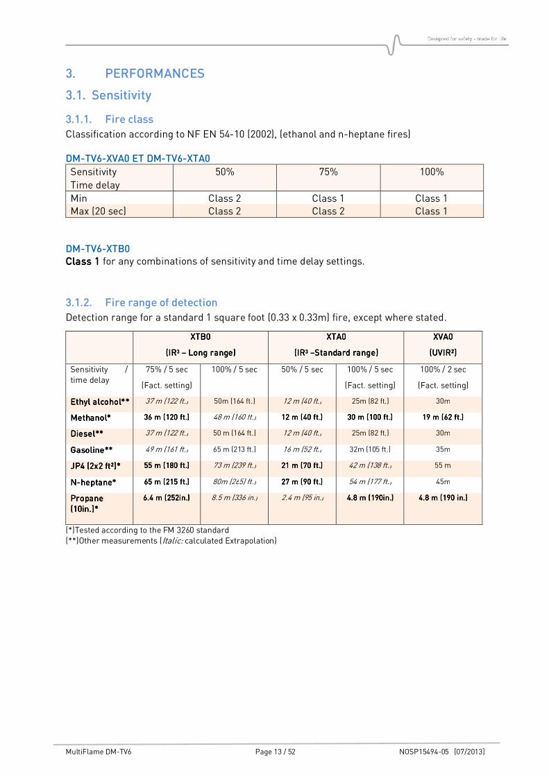
3. PERFORMANCES
3.1. Sensitivity
3.1.1. Fire class
Classification according to NF EN 54-10 (2002), (ethanol and n-heptane fires)
DM-TV6-XVA0 ET DM-TV6-XTA0
Sensitivity
Time delay
50% 75% 100%
Min Class 2 Class 1 Class 1 Max (20 sec) Class 2 Class 2 Class 1
DM-TV6-XTB0 Class 1Class 1Class 1Class 1 for any combinations of sensitivity and time delay settings.
3.1.2. Fire range of detection
Detection range for a standard 1 square foot (0.33 x 0.33m) fire, except where stated.
XTB0XTB0XTB0XTB0
(IR(IR(IR(IR3333 –––– Long range)Long range)Long range)Long range)
XTA0XTA0XTA0XTA0
(IR(IR(IR(IR3333 ––––Standard range)Standard range)Standard range)Standard range)
XVA0XVA0XVA0XVA0
(UV(UV(UV(UVIR²)IR²)IR²)IR²)
Sensitivity / time delay
75% / 5 sec
(Fact. setting)
100% / 5 sec 50% / 5 sec 100% / 5 sec
(Fact. setting)
100% / 2 sec
(Fact. setting)
Ethyl alcohol**Ethyl alcohol**Ethyl alcohol**Ethyl alcohol** 37 m (122 ft.) 50m (164 ft.) 12 m (40 ft.) 25m (82 ft.) 30m
Methanol*Methanol*Methanol*Methanol* 36 m (120 ft.)36 m (120 ft.)36 m (120 ft.)36 m (120 ft.) 48 m (160 ft.) 12 m (40 ft.)12 m (40 ft.)12 m (40 ft.)12 m (40 ft.) 30 m (100 ft.)30 m (100 ft.)30 m (100 ft.)30 m (100 ft.) 19 m (62 ft.)19 m (62 ft.)19 m (62 ft.)19 m (62 ft.)
Diesel**Diesel**Diesel**Diesel** 37 m (122 ft.) 50 m (164 ft.) 12 m (40 ft.) 25m (82 ft.) 30m
Gasoline**Gasoline**Gasoline**Gasoline** 49 m (161 ft.) 65 m (213 ft.) 16 m (52 ft.) 32m (105 ft.) 35m
JP4 (2x2 ft²)*JP4 (2x2 ft²)*JP4 (2x2 ft²)*JP4 (2x2 ft²)* 55 m (180 ft.)55 m (180 ft.)55 m (180 ft.)55 m (180 ft.) 73 m (239 ft.) 21 m (70 ft.)21 m (70 ft.)21 m (70 ft.)21 m (70 ft.) 42 m (138 ft.) 55 m
NNNN----heptane*heptane*heptane*heptane* 65656565 m (2m (2m (2m (215151515 ft.)ft.)ft.)ft.) 80m (265) ft.) 27 m (90 ft.)27 m (90 ft.)27 m (90 ft.)27 m (90 ft.) 54 m (177 ft.) 45m
Propane Propane Propane Propane (10in.)*(10in.)*(10in.)*(10in.)*
6.4 m (252in.)6.4 m (252in.)6.4 m (252in.)6.4 m (252in.) 8.5 m (336 in.) 2.4 m (95 in.) 4.8 m (190in.)4.8 m (190in.)4.8 m (190in.)4.8 m (190in.) 4.8 m (190 in.)4.8 m (190 in.)4.8 m (190 in.)4.8 m (190 in.)
(*)Tested according to the FM 3260 standard (**)Other measurements (Italic: calculated Extrapolation)
MultiFlame DM-TV6 Page 14 / 52 NOSP15494-05 [07/2013]
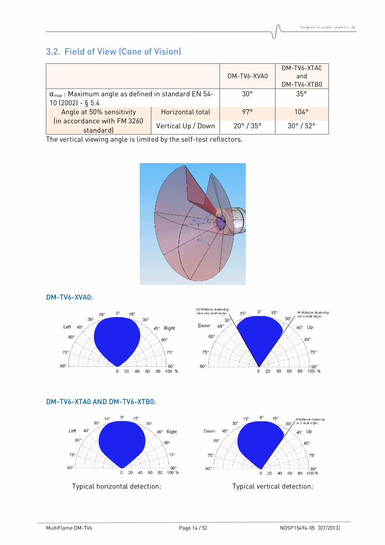
3.2. Field of View (Cone of Vision)
DM-TV6-XVA0 DM-TV6-XTA0
and DM-TV6-XTB0
αmax : Maximum angle as defined in standard EN 54-10 (2002) - § 5.4
30° 35°
Angle at 50% sensitivity (in accordance with FM 3260
standard)
Horizontal total 97° 104°
Vertical Up / Down 20° / 35° 30° / 52°
The vertical viewing angle is limited by the self-test reflectors.
DM-TV6-XVA0:
DM-TV6-XTA0 AND DM-TV6-XTB0:
Typical horizontal detection: Typical vertical detection:
MultiFlame DM-TV6 Page 15 / 52 NOSP15494-05 [07/2013]
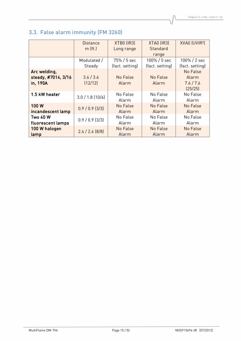
3.3. False alarm immunity (FM 3260)
Distance m (ft.)
XTB0 (IR3) Long range
XTA0 (IR3) Standard range
XVA0 (UVIR²)
Modulated / Steady
75% / 5 sec (fact. setting)
100% / 5 sec (fact. setting)
100% / 2 sec (fact. setting)
Arc welding, Arc welding, Arc welding, Arc welding, steady, #7014, 3/16 steady, #7014, 3/16 steady, #7014, 3/16 steady, #7014, 3/16
in, 190Ain, 190Ain, 190Ain, 190A
3.6 / 3.6
(12/12)
No False
Alarm
No False
Alarm
No False Alarm
7.6 / 7.6 (25/25)
1.5 kW heater1.5 kW heater1.5 kW heater1.5 kW heater 3.0 / 1.8 (10/6)
No False
Alarm
No False
Alarm
No False
Alarm 100 W 100 W 100 W 100 W incandescent lampincandescent lampincandescent lampincandescent lamp
0.9 / 0.9 (3/3) No False Alarm
No False Alarm
No False Alarm
Two 40 W Two 40 W Two 40 W Two 40 W
fluorescent lampsfluorescent lampsfluorescent lampsfluorescent lamps 0.9 / 0.9 (3/3)
No False
Alarm
No False
Alarm
No False
Alarm 100 W halogen 100 W halogen 100 W halogen 100 W halogen lamplamplamplamp
2.4 / 2.4 (8/8) No False Alarm
No False Alarm
No False Alarm
MultiFlame DM-TV6 Page 16 / 52 NOSP15494-05 [07/2013]
4. INSTALLATION
The detector must be installed in accordance with its certification and in
accordance with the standards of the appropriate authority in the country
concerned.
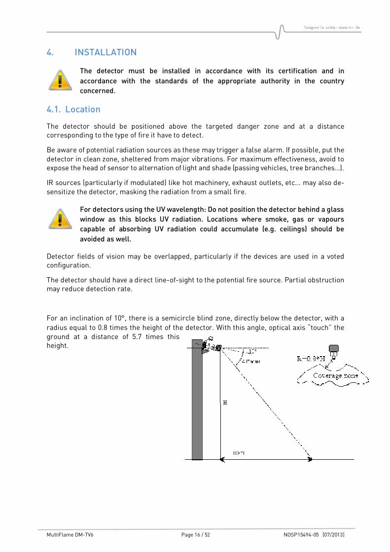
4.1. Location
The detector should be positioned above the targeted danger zone and at a distance corresponding to the type of fire it have to detect.
Be aware of potential radiation sources as these may trigger a false alarm. If possible, put the detector in clean zone, sheltered from major vibrations. For maximum effectiveness, avoid to expose the head of sensor to alternation of light and shade (passing vehicles, tree branches…).
IR sources (particularly if modulated) like hot machinery, exhaust outlets, etc... may also de-sensitize the detector, masking the radiation from a small fire.
For detectors using the UV wavelength: Do not position the detector behind a glass
window as this blocks UV radiation. Locations where smoke, gas or vapours
capable of absorbing UV radiation could accumulate (e.g. ceilings) should be
avoided as well.
Detector fields of vision may be overlapped, particularly if the devices are used in a voted configuration.
The detector should have a direct line-of-sight to the potential fire source. Partial obstruction may reduce detection rate.
For an inclination of 10°, there is a semicircle blind zone, directly below the detector, with a
radius equal to 0.8 times the height of the detector. With this angle, optical axis “touch” the ground at a distance of 5.7 times this height.
MultiFlame DM-TV6 Page 17 / 52 NOSP15494-05 [07/2013]
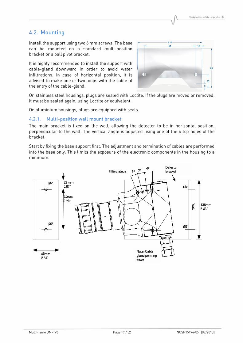
4.2. Mounting
Install the support using two 6 mm screws. The base can be mounted on a standard multi-position bracket or a ball pivot bracket.
It is highly recommended to install the support with cable-gland downward in order to avoid water
infiltrations. In case of horizontal position, it is advised to make one or two loops with the cable at the entry of the cable-gland.
On stainless steel housings, plugs are sealed with Loctite. If the plugs are moved or removed, it must be sealed again, using Loctite or equivalent.
On aluminium housings, plugs are equipped with seals.
4.2.1. Multi-position wall mount bracket
The main bracket is fixed on the wall, allowing the detector to be in horizontal position, perpendicular to the wall. The vertical angle is adjusted using one of the 4 top holes of the bracket.
Start by fixing the base support first. The adjustment and termination of cables are performed
into the base only. This limits the exposure of the electronic components in the housing to a minimum.
MultiFlame DM-TV6 Page 18 / 52 NOSP15494-05 [07/2013]
4.2.2. Detector assembly
Check the presence of the O-ring on explosion proof seal, make sure that it is correctly
greased and has no visible damage. Plug connectors to the base, as described in paragraph “Electric connection”.
Mate the detector housing to the base taking care to arrange any cable excess in the base compartment.
Tighten the assembly bolts at the back of the base into the housing. Depending on how the base is mounted, the detector housing may be rotated (by steps of 90°). The sensor cartridge
IR reflector must always be in the 12 o’clock position (top). When you look at the detector from the front, the IR communication head is on the right side.
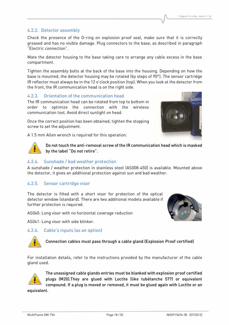
4.2.3. Orientation of the communication head The IR communication head can be rotated from top to bottom in order to optimize the connection with the wireless communication tool. Avoid direct sunlight on head.
Once the correct position has been obtained, tighten the stopping screw to set the adjustment.
A 1.5 mm Allen wrench is required for this operation.
Do not touch the anti-removal screw of the IR communication head which is masked
by the label “Do not retire”.
4.2.4. Sunshade / bad weather protection
A sunshade / weather protection in stainless steel (AS008-450) is available. Mounted above the detector, it gives an additional protection against sun and bad weather.
4.2.5. Sensor cartridge visor
The detector is fitted with a short visor for protection of the optical detector window (standard). There are two additional models available if further protection is required.
AS040: Long visor with no horizontal coverage reduction
AS041: Long visor with side blinker.
4.2.6. Cable‘s inputs (as an option)
Connection cables must pass through a cable gland (Explosion Proof certified)
For installation details, refer to the instructions provided by the manufacturer of the cable gland used.
The unassigned cable glands entries must be blanked with explosion proof certified
plugs (M20).They are glued with Loctite (like tubétanche 577) or equivalent
compound. If a plug is moved or removed, it must be glued again with Loctite or an
equivalent.
MultiFlame DM-TV6 Page 19 / 52 NOSP15494-05 [07/2013]
4.3. Electric Connection
Never adjust electric connections when detectors are powered. Maintenance must
be undertaken by qualified staff. Observe safety site rules.
MultiFlame DM-TV6 is a sensor with standard current output 4-20mA. The connection can be
on 3 or 4 wires. The 4 wires configuration allows insulation between the signal and power loops.
In addition, two independent relays outputs can be connected directly to a controller or signal device.
We recommend using an armoured and shielded cable, type NF M 87 202, in accordance with the requirements for hazardous areas and NF C 15 100.
Other cables can be used if they are compliant with the local regulations and standards.
The table below shows the maximum cable lengths (2-wires) based on a minimum supply voltage.
Min. single wire cross area mm²/AWG 0.5 (20) 0.9 (18) 1.5 (16)
Supply voltage 20VDC, max. cable length in m/ft.* 250/820 400/1310 700/2300
Supply voltage 24VDC, max. cable length in m/ft.* 650/2130 1100/3600 2000/6560
* Those values are indicative ones, for a considered consumption power about 3.5 W
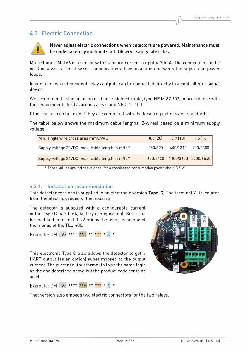
4.3.1. Installation recommendation This detector versions is supplied in an electronic version TypeTypeTypeType----CCCC. The terminal V- is isolated from the electric ground of the housing
The detector is supplied with a configurable current output type C (4-20 mA, factory configuration). But it can
be modified in format 0-22 mA by the user, using one of the menus of the TLU 600.
Example: DM-TV6-****-**C-**-***-*-C-*
This electronic Type C also allows the detector to get a HART output (as an option) superimposed to the output current. The current output format follows the same logic
as the one described above but the product code contains an H:
Example: DM-TV6-****-**H-**-***-*-C-*
That version also embeds two electric connectors for the two relays.
MultiFlame DM-TV6 Page 20 / 52 NOSP15494-05 [07/2013]
Figure 2 : Terminal blocks
Point JP12 & JP13 Description
1 T2 Relay 2
2 C2 Relay 2
3 T1 Relay 1
4 C1 Relay 1
Point JP11 Description
1 V- 0 V
2 V+ +24VDC power supply
3 V+ +24VDC power supply loop (connected to point 2)
4 V- 0 V, Connected to point 1
5 L+ 20mA Current loop: entry
6 L- 20mA Current loop: output
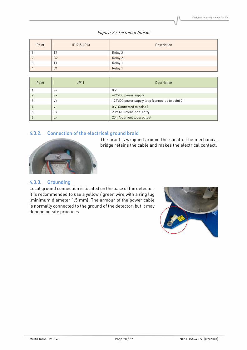
4.3.2. Connection of the electrical ground braid The braid is wrapped around the sheath. The mechanical bridge retains the cable and makes the electrical contact.
4.3.3. Grounding Local ground connection is located on the base of the detector. It is recommended to use a yellow / green wire with a ring lug (minimum diameter 1.5 mm). The armour of the power cable
is normally connected to the ground of the detector, but it may depend on site practices.
MultiFlame DM-TV6 Page 21 / 52 NOSP15494-05 [07/2013]
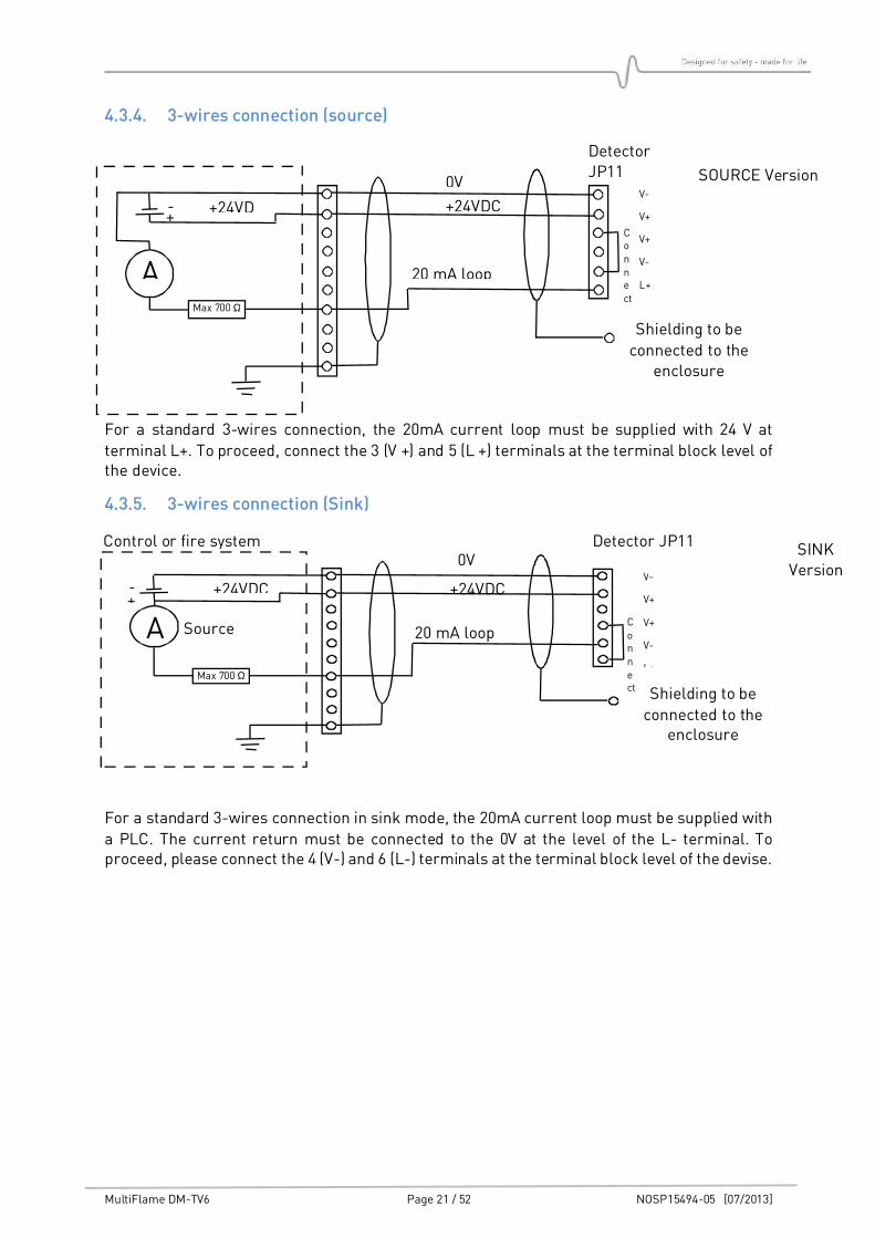
4.3.4. 3-wires connection (source)
For a standard 3-wires connection, the 20mA current loop must be supplied with 24 V at
terminal L+. To proceed, connect the 3 (V +) and 5 (L +) terminals at the terminal block level of the device.
4.3.5. 3-wires connection (Sink)
For a standard 3-wires connection in sink mode, the 20mA current loop must be supplied with
a PLC. The current return must be connected to the 0V at the level of the L- terminal. To proceed, please connect the 4 (V-) and 6 (L-) terminals at the terminal block level of the devise.
A
0V
+24VDC retour
+24VDC
Max 700 Ω
V-
V+
V+
V-
L+
Detector JP11 Control or fire system
Source
Shielding to be
connected to the enclosure
20 mA loop
SINK Version
+ -
Connect
SOURCE Version
A
0V
+24VDC +24VD
Max 700 Ω
V-
V+
V+
V-
L+
Detector JP11
Connect
Shielding to be
connected to the enclosure
20 mA loop
+ -
MultiFlame DM-TV6 Page 22 / 52 NOSP15494-05 [07/2013]
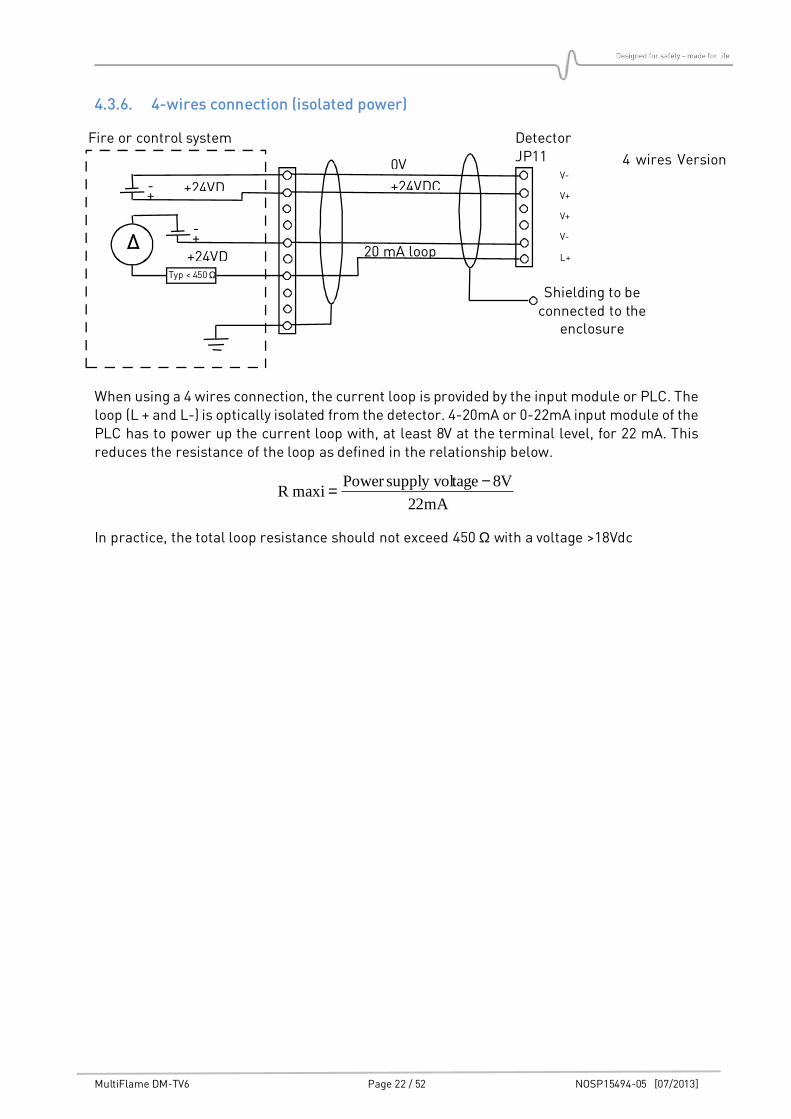
4.3.6. 4-wires connection (isolated power)
When using a 4 wires connection, the current loop is provided by the input module or PLC. The loop (L + and L-) is optically isolated from the detector. 4-20mA or 0-22mA input module of the PLC has to power up the current loop with, at least 8V at the terminal level, for 22 mA. This reduces the resistance of the loop as defined in the relationship below.
mA22
V8tagesupply volPower maxi R
−=
In practice, the total loop resistance should not exceed 450 Ω with a voltage >18Vdc
4 wires Version
A
0V
+24VDC +24VD
Typ < 450 Ω
V-
V+
V+
V-
L+
Detector JP11
Fire or control system
Shielding to be connected to the
enclosure
20 mA loop
+ -
+24VD+ -
MultiFlame DM-TV6 Page 23 / 52 NOSP15494-05 [07/2013]
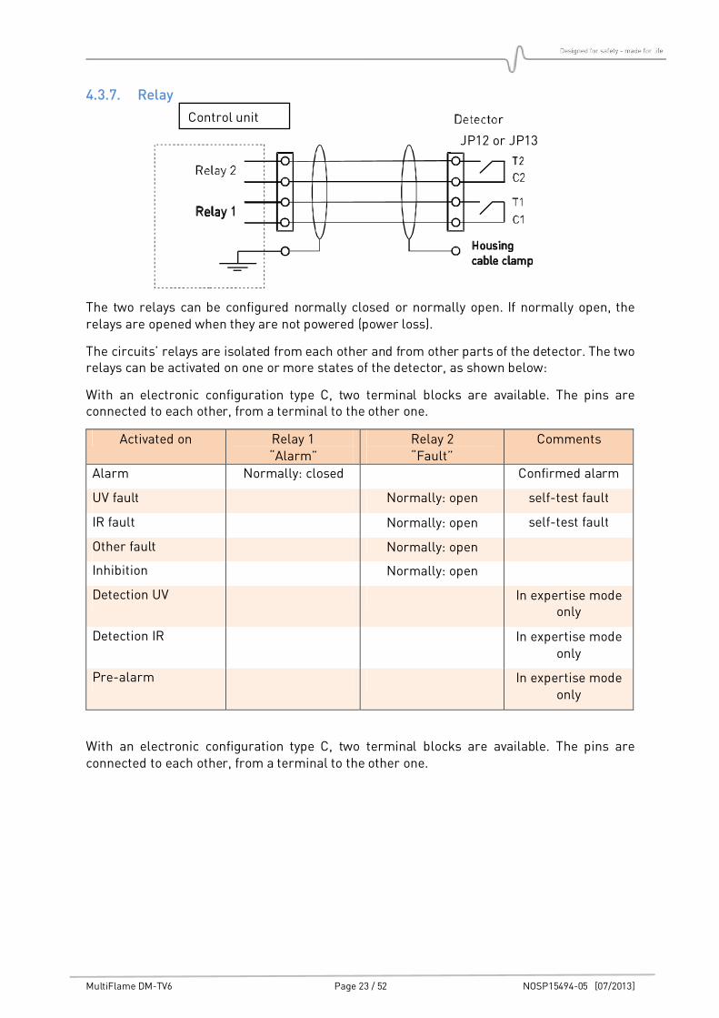
4.3.7. Relay
The two relays can be configured normally closed or normally open. If normally open, the relays are opened when they are not powered (power loss).
The circuits’ relays are isolated from each other and from other parts of the detector. The two relays can be activated on one or more states of the detector, as shown below:
With an electronic configuration type C, two terminal blocks are available. The pins are connected to each other, from a terminal to the other one.
Activated on Relay 1 “Alarm”
Relay 2 “Fault”
Comments
Alarm Normally: closed Confirmed alarm
UV fault Normally: open self-test fault
IR fault Normally: open self-test fault
Other fault Normally: open
Inhibition Normally: open
Detection UV In expertise mode only
Detection IR In expertise mode only
Pre-alarm In expertise mode only
With an electronic configuration type C, two terminal blocks are available. The pins are connected to each other, from a terminal to the other one.
Control unit
JP12 or JP13
MultiFlame DM-TV6 Page 24 / 52 NOSP15494-05 [07/2013]
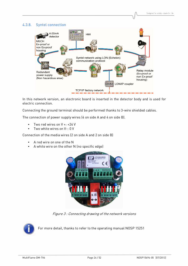
4.3.8. Syntel connection
In this network version, an electronic board is inserted in the detector body and is used for electric connection.
Connecting the ground terminal should be performed thanks to 3-wire shielded cables.
The connection of power supply wires (4 on side A and 4 on side B).
• Two red wires on V +: +24 V • Two white wires on V-: 0 V
Connection of the media wires (2 on side A and 2 on side B)
• A red wire on one of the N • A white wire on the other N (no specific edge)
Figure 3 : Connecting drawing of the network versions
For more detail, thanks to refer to the operating manual NOSP 15251

MultiFlame DM-TV6 Page 25 / 52 NOSP15494-05 [07/2013]
4.4. Detection cartridge
The cartridge is separated from the detector to enable its replacement. Its dismantling is extremely easy and does not need to touch the rest of the unit.
Be careful when plugging or removing the detection cartridge.
• Align the centring pin of the cartridge with the corresponding hole in the housing. • Insert the cartridge in the bell, holding the two parts as parallel as possible. • Introduce the pin in the hole without damaging the cartridge bottom connector when tightening the two parts.
These interventions imperatively requires
power to be off.
The Cartridge is fixed with a threaded fixing ring. Loosen the fixing screw in order to unscrew the cartridge.
MultiFlame DM-TV6 Page 26 / 52 NOSP15494-05 [07/2013]
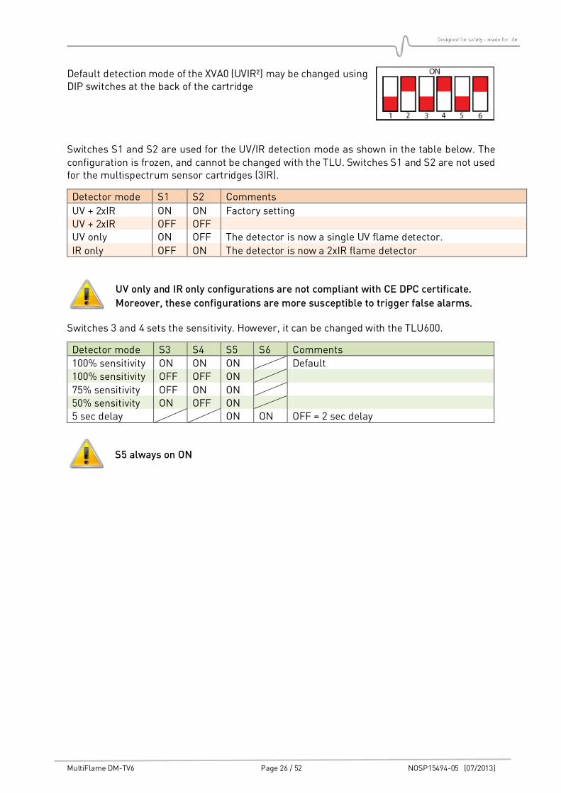
Default detection mode of the XVA0 (UVIR²) may be changed using DIP switches at the back of the cartridge
Switches S1 and S2 are used for the UV/IR detection mode as shown in the table below. The configuration is frozen, and cannot be changed with the TLU. Switches S1 and S2 are not used for the multispectrum sensor cartridges (3IR).
Detector mode S1 S2 Comments
UV + 2xIR ON ON Factory setting UV + 2xIR OFF OFF UV only ON OFF The detector is now a single UV flame detector.
IR only OFF ON The detector is now a 2xIR flame detector
UV only and IR only configurations are not compliant with CE DPC certificate.
Moreover, these configurations are more susceptible to trigger false alarms.
Switches 3 and 4 sets the sensitivity. However, it can be changed with the TLU600.
Detector mode S3 S4 S5 S6 Comments
100% sensitivity ON ON ON Default 100% sensitivity OFF OFF ON
75% sensitivity OFF ON ON 50% sensitivity ON OFF ON 5 sec delay ON ON OFF = 2 sec delay
S5 always on ON
MultiFlame DM-TV6 Page 27 / 52 NOSP15494-05 [07/2013]
5. COMMISSIONING
5.1. Visual inspection
Make certain that all the operations of the “Installation” chapter have been achieved correctly.
Pay particular attention on installation conformity, check the cables entry, the presence of O-rings, and the connexion of the cartridge.
• Check if the detection mode (UV/IR, 3IR) match with the marking
5.2. Power-up
The sensor is powered and operating when the green LED on the communication head is flashing.
• Check the connection to the control unit
5.3. Operational tests
All MultiFlame detectors are delivered set and tested. Some additional tests are necessary to
check the good working of the loop. Please make sure to have all authorizations needed before running the following operations:
• Check the states/information using the wireless configuration tool (TLU)
• Check alarms delay setting : (factory settings)
• 5 seconds for T versions • 2 seconds for V versions
• Eventually, adjut the value up to 20 sec
The alarm state needs the fire detection to be continuously detected over the full temporisation delay to be activated
SENSITIVITY SETTING • Factory settings :
• 100% • Except for XTB0 version (high sensitivity) 75%
• Eventually adjust the sensitivity between 50% / 75% and 100ù of the maximum coverage distance
• Test the channel by trigging an alarm using the LT15 test lamp or force the output to 20mA via the TLU600.
MultiFlame DM-TV6 Page 28 / 52 NOSP15494-05 [07/2013]
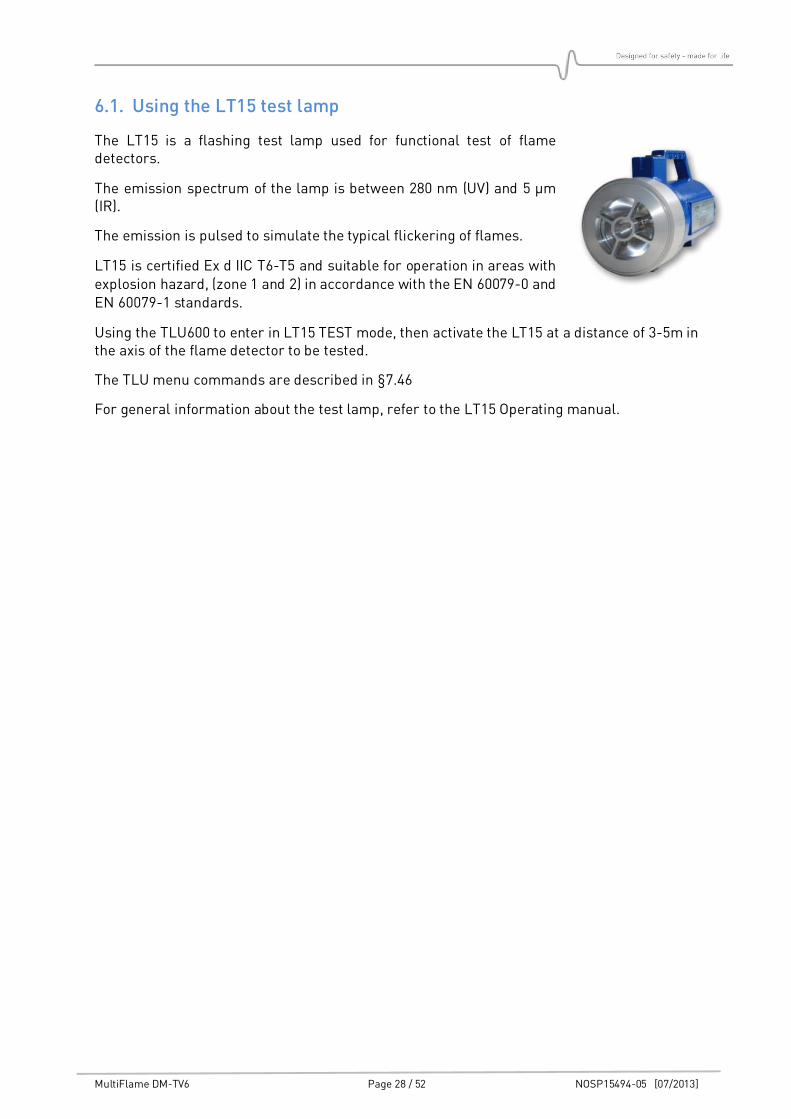
6.1. Using the LT15 test lamp
The LT15 is a flashing test lamp used for functional test of flame detectors.
The emission spectrum of the lamp is between 280 nm (UV) and 5 µm (IR).
The emission is pulsed to simulate the typical flickering of flames.
LT15 is certified Ex d IIC T6-T5 and suitable for operation in areas with explosion hazard, (zone 1 and 2) in accordance with the EN 60079-0 and EN 60079-1 standards.
Using the TLU600 to enter in LT15 TEST mode, then activate the LT15 at a distance of 3-5m in the axis of the flame detector to be tested.
The TLU menu commands are described in §7.46
For general information about the test lamp, refer to the LT15 Operating manual.
MultiFlame DM-TV6 Page 29 / 52 NOSP15494-05 [07/2013]
7. OPERATION
7.1. Environmental conditions
• Dust: Dust on the window may limit UV sensitivity
• Oil vapour: Oil vapour on the window can reduce UV sensitivity
• Water/Ice: Water or ice can reduce infrared flame detector performances
7.2. Inhibition
Maintenance Inhibition is temporary. It appears during power up and maintenance phases.
Inhibition stops automatically when the operator get out of the maintenance menus or 10 minutes after the end of communication with the TLU.
Maintenance inhibition can be configured in "frozen" mode (Factory setting) or in "free" mode.
• In "frozen" mode, outputs (current and relay) remain in their previous state. For example, if the device indicated a failure (2.0 mA), this state would be maintained during the inhibition.
• If the unit is configured in "free" inhibition mode, the output current will be on the same level as for the permanent inhibition
The permanent inhibition is activated by an order issued by the TLU when an operation is
performed at or around the device, or when the operator wants to inhibit a faulty device. The permanent inhibition must be removed by an operator’s deliberate action using the TLU.
When working with the LT15 test lamp, the detector must be in TEST-mode. The default output is in maintenance inhibition; but the detector’s outputs (current loop and relays) may be activated in order to test the complete loop (Requires access level 2 on the TLU).
Local LED and Information on the TLU are activated.
MultiFlame DM-TV6 Page 30 / 52 NOSP15494-05 [07/2013]
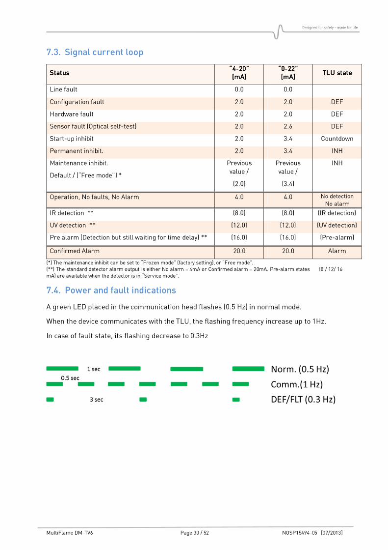
7.3. Signal current loop
StatusStatusStatusStatus “4“4“4“4----20”20”20”20” [mA][mA][mA][mA]
“0“0“0“0----22”22”22”22” [mA][mA][mA][mA]
TLU stateTLU stateTLU stateTLU state
Line fault 0.0 0.0
Configuration fault 2.0 2.0 DEF
Hardware fault 2.0 2.0 DEF
Sensor fault (Optical self-test) 2.0 2.6 DEF
Start-up inhibit 2.0 3.4 Countdown
Permanent inhibit. 2.0 3.4 INH
Maintenance inhibit.
Default / (“Free mode”) *
Previous value /
(2.0)
Previous value /
(3.4)
INH
Operation, No faults, No Alarm 4.0 4.0 No detection No alarm
IR detection ** (8.0) (8.0) (IR detection)
UV detection ** (12.0) (12.0) (UV detection)
Pre alarm (Detection but still waiting for time delay) ** (16.0) (16.0) (Pre-alarm)
Confirmed Alarm 20.0 20.0 Alarm
(*) The maintenance inhibit can be set to “Frozen mode” (factory setting), or “Free mode”. (**) The standard detector alarm output is either No alarm = 4mA or Confirmed alarm = 20mA. Pre-alarm states (8 / 12/ 16 mA) are available when the detector is in “Service mode”.
7.4. Power and fault indications
A green LED placed in the communication head flashes (0.5 Hz) in normal mode.
When the device communicates with the TLU, the flashing frequency increase up to 1Hz.
In case of fault state, its flashing decrease to 0.3Hz
MultiFlame DM-TV6 Page 31 / 52 NOSP15494-05 [07/2013]
7.5. Alarm indication (LED)
A red LED placed in the communication head flashes in case of confirmed alarm state.
In standard configuration, the alarm LED is memorized. The flashing continues until be acknowledged with the TLU or until the detector is powered off, then powered on again.
For DM-TV6-X##0-0X#-0N0N0N0N versions, the alarm LED memorization is off. The LED stops flashing when the alarm disappears.
DM-TV6-X##0-0X#-0N0N0N0N version is not fully EN 54-10 compliant
If the alarm is memorized, the flashing red LED remains until the alarm is
acknowledged (TLU/TLH or OFF/ON)
MultiFlame DM-TV6 Page 32 / 52 NOSP15494-05 [07/2013]
7.6. Wireless communication tool TLU600
All settings and tests of detectors can be done by the wireless communication tool TLU600.
This communication tool and its software are compatible with all Simtronics detectors: MultiFlame, MultiTox and MultiXplo. Communication is made via infrared link (IrDA), similar but more efficient than infrared links for computers. IrDA head should not be placed facing the sun as it significantly reduces the communication with the TLU600.
Please refer to the wireless communication tool operating manual for more details
When a device is in communication with the TLU, the frequency of the green LED
(in the head of communication) flashing is set to 1Hz. By this way, the user can
ensure he communicates with the requested device.
The TLU600 menu is composed of 2 access levels allowing both settings and obtaining information about detector’s status.
• level 1 : exploitation • level 2 : Maintenance
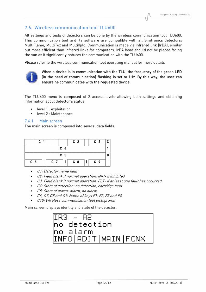
7.6.1. Main screen The main screen is composed into several data fields.
C 1 C 2 C 3 C
C 4 1
C 5 0
C 6 | C 7 | C 8 | C 9
• C1: Detector name field • C2: Field blank if normal operation; INH- if inhibited • C3: Field blank if normal operation; FLT- if at least one fault has occurred • C4: State of detection: no detection, cartridge fault • C5: State of alarm: alarm, no alarm • C6, C7, C8 and C9: Name of keys F1, F2, F3 and F4 • C10: Wireless communication tool pictograms
Main screen displays identity and state of the detector.
MultiFlame DM-TV6 Page 33 / 52 NOSP15494-05 [07/2013]
7.6.2. General operation The user can navigate through the menu with the F1 to F4 keys, whose functions change depending on the fields displayed above each key. Standard functions:
• >>>> Scroll function / next screen. • ESC Exit the current menu and return to the previous one. • CHG Changing displayed value. • VAL Validation and Check-in of the changed value.
The changed value must be confirmed by pressing [VAL] key, otherwise the old
value will be kept when leaving the menu.
MultiFlame DM-TV6 Page 34 / 52 NOSP15494-05 [07/2013]
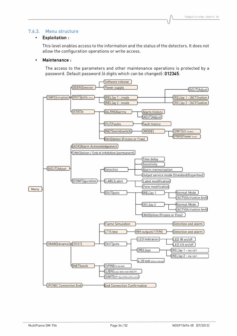
7.6.3. Menu structure
• ExploitationExploitationExploitationExploitation : : : :
This level enables access to the information and the status of the detectors. It does not allow the configuration operations or write access.
• MaintenanceMaintenanceMaintenanceMaintenance ::::
The access to the parameters and other maintenance operations is protected by a password. Default password (6 digits which can be changed): 012301230123012345454545.
MultiFlame DM-TV6 Page 35 / 52 NOSP15494-05 [07/2013]
7.7. Information menu [INFO]
The information menu contains all information concerning the identity and settings of the detector. The first screen gives the detector’s reference and its serial number.
7.7.1. [IDEN]tity submenu Presentation of:
• detector operation mode (UV/2IR, UV, IR(2IR or 3IR)) • Sensor sensitivity (50, 75, 100%) • Alarm time delay (seconds)
Sub-menus present the board software version and the power supply voltage.
7.7.2. [OUT]put submenu Presentation of:
• Current protocol (0-22 mA or 4-20 mA).
• Normal state of the relays (normally open or normally closed). • Condition of relays activation.
Relays can be set with a level 2 access.
7.7.3. [STAT]e Information submenu Presentation of:
• Alarms history • Alarm activation • Faults list (use F1 key to scroll faults) • Alarm counter since last reset • Failed optical self-test counter since last reset
7.7.3.1. [ALRM] Alarm screen Allows Alarms history display.
7.7.3.2. [FLT.] Fault screen Displays a list of eventual faults (press F1 key to scroll through the list)
7.7.3.3. Network Screen Switch This menu and its sub-menus are used for the network detector settings. For any further details, please refer to the Syntel system operating manuals.
MODE SCREEN
The first line shows the operating mode of the sensor in the network (logic link test/out of order/emulation).
The second line shows if the network part of the detector is “operating” or “out of order”. For any further details, please refer to the Syntel system operating manuals.
NETWORK SCREEN: ALIM
Information displayed:
• Voltage A: ON / OFF • Voltage B: ON / OFF
For any further details, please refer to the Syntel system operating manuals
MultiFlame DM-TV6 Page 36 / 52 NOSP15494-05 [07/2013]
7.7.3.4. [INH] screen This screen is dedicated to verify the inhibition mode configuration (frozen or free). If the access level permits it, it is possible to change this setting.
7.8. Adjustment menu [ADJT]
This menu presents all the detector settings. All the functionalities, except alarm level acknowledgment, request access level 2.
7.8.1. Alarm Acknowledgement
This menu enables the acknowledgement of the memorized alarms. The alarm can be acknowledged only if the alarm condition has disappeared.
7.8.2. Inhibition / End of inhibition
The inhibition (called permanent inhibition) is activated or deactivated manually using the
menu. This function is used for deactivating the detector outputs (example: during maintenance).
The « inhibition » menu is available if the sensor is not in inhibition, maintenance inhibition or simulation.Selecting the inhibition mode will switch the detector in inhibition mode.
The message “End of inhibition” is displayed on the TLU. Press on “End of inhibition” to get the detector back to normal operating mode.
7.8.3. [CONF]iguration sub-menu
This menu gives access to the detection configuration menu (time delays, sensitivity, alarm
memorization), to the label and zone configuration, the relay output configurations as well as the configuration of the outputs states control.
7.8.3.1. Detection [Adjust] / [Config] / [Detection]
ALARM / PRE ALARM TIME DELAY SETTINGS:
Time delay can be changed to suit the application. Some locations need a longer delay to suppress interference (Example: Gas turbines). Delay is adjustable in a range of 0 to 20 seconds. Please use TLU600 to enter the two digits number.
• DM-TV6-V factory setting: 2 sec (minimum 2 sec)
• DM-TV6-T factory setting: 5 sec (minimum 3 sec). Also valid for UV and 2IR mode.
SENSITIVITY SETTINGS:
Detection range is available in three steps: 100%, 75% and 50%. This refers to the actual range and not optical signal strength.
ALARM MEMORIZATION SETTINGS:
Alarm and pre alarms can be memorized. Use the CHG key to move from “memorized” to “not memorized” (yes / no). Current status is indicated by a flashing “yes” or “no”.
If the memorization of alarms is activated, the alarms have to be manually acknowledged either using the TLU, or shutting down the detector power supply and switching it up again from the controller.
MultiFlame DM-TV6 Page 37 / 52 NOSP15494-05 [07/2013]
OUTPUT SERVICE MODE:
• “Standard mode” All pre-alarms, UV or IR detections are disabled. Information is sent in case of
confirmed alarm only.
• “Expertise mode” Current outputs, relays and LEDs, will be activated on pre-alarm, UV or IR detection (Ref 7.3).
7.8.3.2. Label and zone sub-menu
This menu allows label and zone’s modification. After selecting a label or a zone, the
modification function operates in the same manner. Both “Label” and “Zone” fields are free text type for identification of the detector (name and position of the detector).
To edit fields, Select [label] or [zone] and:
• Press on the corresponding numeric key to select a figure. • Press [>>>>>>>>] to go to the next figure in the field. • Press [PAGE] to go next page.
7.8.3.3. Output [Set] / [Config] / [Outputs]
This menu gives access to the configuration of the relay operating mode and to conditions of activations.
STATE OF THE RELAYS: Each relay can be configured:
• Normally open (not energized) • Normally closed (energized)
ACTIVATION OF THE RELAYS:
Each relay can be activated on one or several following conditions:
- IR detection (Service mode only) - UV detection (Service mode only) - Pre-alarm (Service mode only)
- Alarm - UV detection fault - IR detection fault - On all fault - Inhibition
MAINTENANCE INHIBITION:
Sets how the temporary maintenance inhibition (power up, optical test, etc.) affects the outputs. Choose “Frozen” (factory setting) or “Free”. More details in §7.2.
MultiFlame DM-TV6 Page 38 / 52 NOSP15494-05 [07/2013]
7.9. The maintenance menu [MAIN]
7.9.1. Test sub-menu
The maintenance menu handles testing of the detector:
• Flame simulation using the integrated test lamps
• Detection tests using LT15 test lamp or a test fire
• Relay output and LED tests
Entering the test menu enables the temporary maintenance inhibition mode... The detector exits the test menu and inhibition automatically after 10 minutes of TLU inactivity.
7.9.1.1. Flame simulation This menu initiates an optical test using the integrated test lamps.
Test results are indicated by the detector LEDs and on the TLU. However, there is no action on the outputs (Relays and 4-20mA interface).
7.9.1.2. LT 15 test menu
This menu enables manually tests on detection, using either a test fire or a test lamp (Type LT15 SIMTRONICS).
In this mode, “false alarms rejection” algorithms are by-passed, to make a simulated alarm easier to achieve.
All local indicators are activated (front cartridge LEDs, communication head red flashing LED, remote controller display). While entering into the menu, the detector will ask for outputs (current loop and relay) activation.
7.9.1.3. Output This menu allows the user to force the detector output state for loop testing:
• Individual test of the UV and IR LEDs.
• Individual activation of each relay.
• Setting analogue 4-20mA output. Available values are: 0 mA, 2 mA, 3.4 mA, 4 mA, 8 mA, 12 mA, 16 mA and 20 mA by pressing on ++ or -- pad.
7.9.2. Network
This menu is related to the Network variant of the detector (Syntel system).
MultiFlame DM-TV6 Page 39 / 52 NOSP15494-05 [07/2013]
8. HART COMMUNICATION
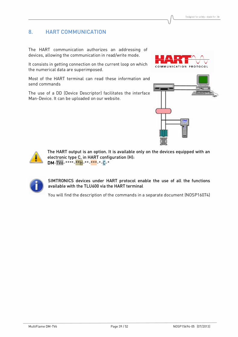
The HART communication authorizes an addressing of devices, allowing the communication in read/write mode.
It consists in getting connection on the current loop on which the numerical data are superimposed.
Most of the HART terminal can read these information and send commands
The use of a DD (Device Descriptor) facilitates the interface Man-Device. It can be uploaded on our website.
The HART output is an option. It is available only on the devices equipped with an electronic type C, in HART configuration (H): DMDMDMDM-TV6-****-**H-**-***-*-C-*
SIMTRONICS devices under HART protocol enable the use of all the functions available with the TLU600 via the HART terminal
You will find the description of the commands in a separate document (NOSP16074)
MultiFlame DM-TV6 Page 40 / 52 NOSP15494-05 [07/2013]
9. MAINTENANCE
The interventions described in this chapter must be performed by competent and
qualified staff. Device performances may be affected if the present instructions are
not respected.
Cartridge unplug or device opening imperatively require power to be OFF.
9.1. Periodic maintenance
We recommend, at least, an annual check.
9.1.1. Visual inspection
Check detector positioning and orientation to be sure that there are no obstacle between the sensor and the potential source of fire.
9.1.2. Cleaning optical parts
Maintenance of flame detectors mainly relates to keeping the optical surfaces clean (window and reflector inside surface). In most installations a periodic cleaning is required.
Clean the detector window and the test reflectors (inside), using a soft cloth soaked in a 50/50 mixture of Ethanol and water.
9.1.3. Flame simulation
Initiate a flame test using the integrated test lamps as described in 7.9.1.1. This can also be achieved using the LT15 test lamp as described in the LT15 operating Manual. Make sure that the detector is set in LT15 test mode as described in 7.9.1.2.
This test inhibits the outputs (relays and current loop), so test results are displayed on the TLU, as well as the alarm LED.
9.1.4. Loop test
To test the full loop there are two options:
• Force sensor outputs manually with the TLU as described in 7.9.1.3.
• An end to end test may also achieved by setting the detector in service mode (7.9.1.2) And initiate an alarm with the LT15 test lamp.
Make sure that connections to the control system or fire panel and other links to extinguishing equipment are under control, avoiding unwanted alarms.
MultiFlame DM-TV6 Page 41 / 52 NOSP15494-05 [07/2013]
9.2. List of main faults
In addition of the current loop faults, other information are available from the wireless
communication tool TLU600/610 (refer to §7.6). If the detector does not work properly, the following table can help you to determine the causes and effects of different possible troubles.
SymptomSymptomSymptomSymptom Possible causePossible causePossible causePossible cause ActioActioActioAction / Checkn / Checkn / Checkn / Check
Green LED goes out Power supply fault Check power supply voltage at power supply and then at detector
No signal (4-20mA) Power supply fault Check power supply voltage at power supply and then at detector
Line fault Check line continuity.
Current loop power supply fault
Check by inserting a milliamp meter into the loop. 4 wire connections only.
No connection with remote controller
No power supply to sensor
Is the green LED is flashing?
Dialogue problem Try to use the TLU on another detector to confirm TLU operation.
UV or IR detection fault.
Detector window contaminated
Clean the detector window and test reflectors.
(The optical self-test has failed)
Faulty sensor. If a LT15 flame test fails, then one or more of the optical sensors are faulty. Return the sensor cartridge to the factory
Faulty self-test lamp. If the above test succeeds, the sensors are OK, but the integrated test lamp is probably faulty. Return the sensor cartridge to the factory
Detector fault Faulty electronics Replace the detector.
9.3. Replacing the cartridge
Follow the instruction in § 4.4.
9.4. Replacing the complete detector
If the operator needs to replace the complete detector, the easiest way is to take off the main housing from the base of the detector (for more details, refer to § 4.2.2).
As the base of the detector remains in place, cable glands do not need to be dismantled. If the detector is not replaced immediately, the “open” base must be protected against humidity, dust and shocks
No intervention should be performed when detector is powered.
MultiFlame DM-TV6 Page 42 / 52 NOSP15494-05 [07/2013]
10. WARNINGS
This document is not contractual. The product characteristics may be modified without prior notice for improvement purposes or for upgrading to meet applicable standards.
10.1. Safety
These devices are certified to be used in hazardous areas. Install and use the detectors in accordance with local and national regulations.
The detector must be properly grounded for protection against electric shocks and minimize electrical interference.
The detector must be installed and handled only by qualified personnel.
There is no part that can be changed or repaired by the user. Calibration is done at the factory,
it must be checked periodically. Return the product to the factory for any maintenance or repair outside the scope of calibration.
10.2. Ownership and confidentiality
The information, design data, drawings and diagrams contained in this document remain the property of SIMTRONICS and are confidential.
The information contained in this document cannot be used, either partially or wholly, nor divulged or reproduced without the prior agreement of SIMTRONICS.
MultiFlame DM-TV6 Page 43 / 52 NOSP15494-05 [07/2013]
11. WARRANTY
DM-TV6 are warranted 2 years. Application of the equipment warranty is subject to compliance with the state of the art and the operating instructions contained in this manual.
The SIMTRONICS warranty shall not apply; furthermore SIMTRONICS declines all liability, for damage to equipment or harmful accidents caused by negligence, failure to supervise the equipment or failure to use the equipment in compliance with the applicable recommendations, standards and regulations stipulated in the present manual.
The SIMTRONICS warranty shall not apply to faults resulting either, from materials supplied by the Purchaser, from design imposed by the Purchaser, from servicing or maintenance carried out on SIMTRONICS equipment by a third party not explicitly authorized, or from the use of unsuitable storage conditions.
In order to guarantee correct operation of the system, any addition of equipment to the system or any modification of the installation must be validated by SIMTRONICS.
MultiFlame DM-TV6 Page 44 / 52 NOSP15494-05 [07/2013]
12. CERTIFICATIONS AND STANDARDS
12.1. Standards
The MultiFlame DM-TV6 has been certified according to ATEX Directive 94/9/CE, EMC Directive
2004/108/CE, DPC 89/106/CEE and requirements lay down by the following standards: EN 60079-0/IEC 60079-0 Electrical apparatus for potentially explosive atmospheres.
General requirements
EN 60079-1/IEC 60079-1 Electrical apparatus for potentially explosive atmospheres. Flameproof enclosure "d"
EN 54-10 (2002) EN 54-10/A1 (2006) (Update pending)(Update pending)(Update pending)(Update pending)
Fire detection and fire alarm systems. Part 10 : Flame detectors – Point detectors
EN 50130-4 (Update pending)(Update pending)(Update pending)(Update pending)
Electromagnetic compatibility - Product family standard: Immunity requirements for components of fire, intruder and social alarm systems
12.2. Functional Safety (update pending)
The DM-TV6-V and the DM-TV6-T are suitable for use in SIL2SIL2SIL2SIL2 systems, third party certified references N° FS-*-T-201001591940/1 and FS-*-T-201001591940/2 respectively. IEC 61508 part 1 to 3 (Update pending)(Update pending)(Update pending)(Update pending)
Functional safety of electrical/electronic/ programmable electronic safety (SIL 2)
12.3. Approvals
ATEX LCIE 03 ATEX 6257, LCIE 03 ATEX 6263
IECEx LCI 09.0019, LCI 09.0018
MarED 0062/11 (Bureau Véritas) (config version 00B) Certificates N°23160/A0 EC (B module) and SMS.MED.D/81256/A.0 (D module)
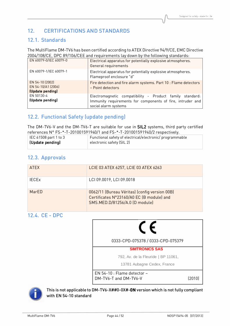
12.4. CE - DPC
This is not applicable to DM-TV6-X##0-0X#-0N0N0N0N version which is not fully compliant
with EN 54-10 standard
0333-CPD-075378 / 0333-CPD-075379
SIMTRONICS SAS..
.792, Av. de la Fleuride | BP 11061,
13781 Aubagne Cedex, France
EN 54-10 : Flame detector – DM-TV6-T and DM-TV6-V (2010)
MultiFlame DM-TV6 Page 45 / 52 NOSP15494-05 [07/2013]
12.5. Marking
12.5.1. ATEX / IECEx versions The MultiFlame identification labels are located on the main detector housing in accordance with the ATEX directive 94/9/CE and EN 54-10
- Manufacturer: SIMTRONICS
- Model: DM-TV6…
- Serial n°: S/N: xxxxyymm
- Approval type: CE 0081 II 2 G / Ex d IIC T6 Gb
- Certification number: ATEX: LCIE 03 ATEX 6257, LCIE 03 ATEX 6263
IECEx: LCI 09.0019, LCI 09.0018
- Temperature: -20°C < Ta < +65°C
CE DPC : 0333-CPD-075378 / 0333-CPD-075379
- Warnings: Warning - Do not open while energized
- Protection: IP66
- Voltage: VDC: 24 V
- Power consumption: 5 W
12.5.2. Version MarED This marking concerns the MarED versions of the DM-TV6 which are compliant with the requirements of the directive 96/98/CE as amended by commission directive 2009/26/CE and of the ATEX directive 94/9/EC. These versions have been subjected to verifications according
to the following standards:
• IEC 60092-504
• IEC 60533
A EC-Type examination certificate N° 23160/A0 EC, and a MED 96/98/EC quality system module D certificate SMS.MED.D/81256/A.0 have been obtained.
The tag mentions the following information: 0062/xx0062/xx0062/xx0062/xx
xx is the production year of the material
MultiFlame DM-TV6 Page 46 / 52 NOSP15494-05 [07/2013]
13. ACCESSORIES AND SPAREPARTS
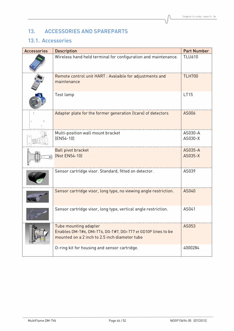
13.1. Accessories
Accessories Description Part Number
Wireless hand held terminal for configuration and maintenance. TLU610
Remote control unit HART : Avalaible for adjustments and maintenance
TLH700
Test lamp LT15
Adapter plate for the former generation (Icare) of detectors AS006
Multi-position wall mount bracket (EN54-10)
AS030-A AS030-X
Ball pivot bracket
(Not EN54-10)
AS035-A
AS035-X
Sensor cartridge visor. Standard, fitted on detector. AS039
Sensor cartridge visor, long type, no viewing angle restriction. AS040
Sensor cartridge visor, long type, vertical angle restriction. AS041
Tube mounting adapter Enables DM-T#6, DMi-TT6, DG-T#7, DGi-TT7 et GD10P lines to be
mounted on a 2 inch to 2.5 inch diameter tube
AS053
O-ring kit for housing and sensor cartridge.
4000284
MultiFlame DM-TV6 Page 47 / 52 NOSP15494-05 [07/2013]
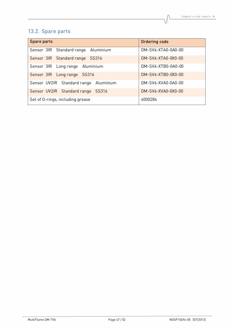
13.2. Spare parts
Spare parts Ordering code
Sensor 3IR Standard range Aluminium DM-SV6-XTA0-0A0-00
Sensor 3IR Standard range SS316 DM-SV6-XTA0-0X0-00
Sensor 3IR Long range Aluminium DM-SV6-XTB0-0A0-00
Sensor 3IR Long range SS316 DM-SV6-XTB0-0X0-00
Sensor UV2IR Standard range Aluminium DM-SV6-XVA0-0A0-00
Sensor UV2IR Standard range SS316 DM-SV6-XVA0-0X0-00
Set of O-rings, including grease 4000284
MultiFlame DM-TV6 Page 48 / 52 NOSP15494-05 [07/2013]
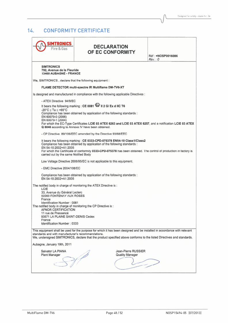
14. CONFORMITY CERTIFICATE
MultiFlame DM-TV6 Page 49 / 52 NOSP15494-05 [07/2013]
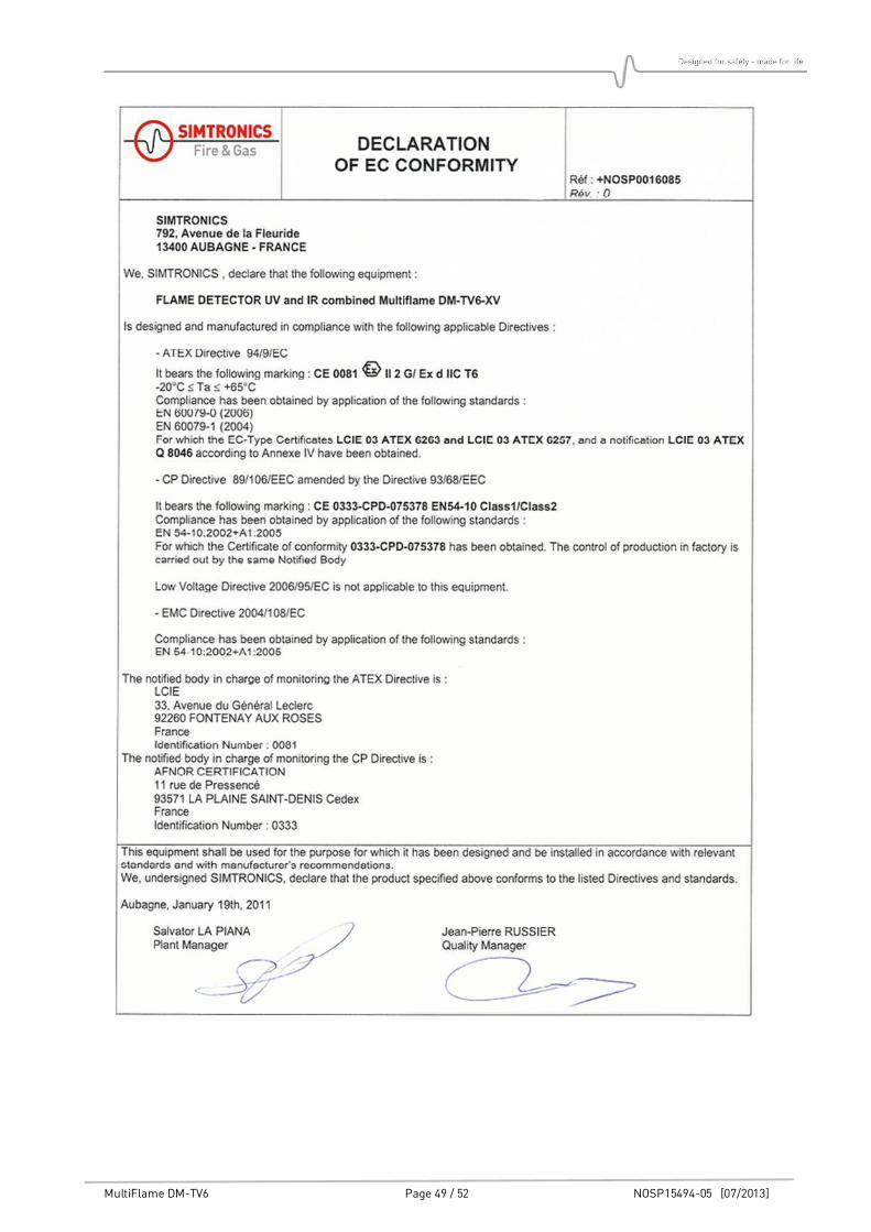
MultiFlame DM-TV6 Page 50 / 52 NOSP15494-05 [07/2013]
MultiFlame DM-TV6 Page 51 / 52 NOSP15494-05 [07/2013]
15. CONTACT DETAILS
You will find an updated list of distributors on our web site:
www.simtronics.eu
Email address for general enquiries: [email protected]
Simtronics SAS 792, av de la Fleuride
BP 11016, 13781 AUBAGNE CEDEX – France Tel: +33 (0) 442 180 600 Simtronics AS
Kabelgaten 8, Økern Næringspark PO Box 314, Økern, NO-0511 Oslo, Norway Tel: +47 2264 5055


![UkuLELe NIGHTS Songbook 6 Books... · 2 Call Me Intro/Riff: Dm / Dm G F / Dm / Dm F C / Repeat [Dm] Colour me your colour, baby, [Bb] Color me your car [Dm] Colour me your colour,](https://static.documents.pub/doc/80x56/5f51f397ce75a731462bf370/ukulele-nights-songbook-6-books-2-call-me-introriff-dm-dm-g-f-dm-dm.jpg)


![No Model VIN 1 (DM) SANTAFE [DM] KMHSU81BSCU000212 2 … Engine YF and D… · 37 (dm) santafe [dm] kmhst81bsdu023920 38 (dm) santafe [dm] kmhst81bsdu023926 39 (dm) santafe [dm] kmhst81bsdu023930](https://static.documents.pub/doc/80x56/6017564e29e54a6dde7ebe6b/no-model-vin-1-dm-santafe-dm-kmhsu81bscu000212-2-engine-yf-and-d-37-dm-santafe.jpg)


