1Key Laboratory of Optical Communication and Lightwave Technologies,Ministry of Education, School of Electronic Engineering, Beijing University of Posts
and Telecommunications, Beijing, 100876, China2School of Computer and Communication, Hunan University, Changsha,
1. IntroductionWith the rapid development of ultrabroadband wireless access in the millimeter-(mm-) wave band, it is of ultimate importance to cost-effectively generate a mm-waveradio signal suited for long-distance transmission [1]. Since generation of themm-wave signal with tens of gigahertz meets the electric bottleneck and themm-wave signal suffers from large loss during transmission along a coaxial cable or inthe air, it is difficult to generate and distribute a high-frequency mm-wave in the elec-trical domain. Radio-over-fiber (RoF) technology can generate the mm-wave signalbased on microwave photonics, which is called an optical mm-wave, and distribute itover the fiber in the optical domain; thus it has many advantages and is an attractivepotential method [2,3]. Essentially, an optical mm-wave is a laser beam consisting oftwo or more coherent longitudinal modes with frequency spacing equal to the wantedmm-wave. As the longitudinal modes beat with each other in the photodiode, therequired electrical mm-wave is generated.
Recently, many methods have been developed to generate such multimode laserbeams as a dual-mode laser [4], dual lasers with different wavelengths locked by opti-cal phase locking and/or injection phase locking [5,6], optical external modulation [7],and optical nonlinear effects of four-wave mixing or stimulated Brillouin scattering[8,9]. Since the two longitudinal modes generated by a dual-mode laser or two sepa-rate lasers have low coherency, the mm-wave generated by their beating has poorspectral purity. The longitudinal modes generated by the nonlinear effects havehigher coherency, but higher pump powers are required and their conversion efficien-cies are low. Moreover, since the Brillouin frequency shift is fixed in the fiber, the gen-erated optical mm-wave is frequency limited. Optical external modulation is a prom-ising scheme for generating an optical mm-wave because of its many merits: (1) thegenerated optical mm-wave has higher coherency since the longitudinal modes comefrom the same source by frequency shift via radio-frequency (rf) modulation, (2) thefrequency of the optical mm-wave may be several times the local oscillator frequency,(3) the optical source noise has little influence on the mm-wave after it is detected bythe photocurrent, (4) and external modulation has a higher conversion efficiency.Since the modulator response frequency and the local oscillator frequency increase as
Vol. 7, No. 10 / October 2008 / JOURNAL OF OPTICAL NETWORKING 838
the frequency of the generated optical mm-wave increases, the equipment perfor-mance requirements are improved greatly, especially for the optical mm-wave bandsignal generated on the basis of linear modulation. The nonlinear modulation can gen-erate higher-order harmonics, which reduces the frequency requirement of the modu-lator and the local oscillator greatly [10–14]. Based on the periodical response charac-teristic of the LiNbO3 Mach–Zehnder modulator (LN-MZM), the local frequency isreduced to half or a quarter of the generated mm-wave by properly configuring themodulator [10,11,14]. In this paper, what we believe to be a new scheme is proposed togenerate the optical mm-wave with eightfold frequency of the local oscillator with anested LN-MZM, and the frequency requirement of the modulator and the local oscil-lator is further reduced.
2. PrincipleThe principle scheme of optical mm-wave generation is shown in Fig. 1. The lightwaveemitted from the laser diode (LD) is injected into an integrated nested MZM, whichconsists of two sub-MZMs (MZ-a and MZ-b) in parallel with identical optical length.V�a and V�b are their switching voltages, and Va and Vb are their bias voltages,respectively. The input lightwave at �c is equally split into two beams by the Y branchwith an optical power splitting ratio of 0.5. The two sub-MZMs are dc biased at themaximum optical output point �Va=Vb=0� and are driven by the rf local oscillatorVrf cos �mt with a � /2 phase shift, so the output lightwave can be expressed as
Here E0 and �c are the lightwave amplitude and angular frequency, respectively, and�1−�� is the modulator insertion loss. We define the modulation index
Fig. 1. Proposed scheme to generate the optical mm-wave with octupling of the fre-quency of the local oscillator via a nested MZM. PD, photodiode; EDFA, erbium-dopedfiber amplifier.
Vol. 7, No. 10 / October 2008 / JOURNAL OF OPTICAL NETWORKING 839
mh��Vpp/2V�=�Vrf /V�, where Vpp=2Vrf is the peak-to-peak voltage of the rf localoscillator signal. Jk� � is the kth-order Bessel function of the first kind. Equation (1)indicates that both MZ-a and MZ-b generate only the even-order sidebands while theodd-order sidebands are suppressed. But, the �4�+2�th-order sidebands of the twooutputs have reverse phase, so the �4�+2�th-order sidebands are added destructivelyand cancelled, as shown in Fig. 1.
According to the characteristics of the Bessel functions given in Fig. 2, the eighth-order and other higher-order sidebands have much smaller amplitudes, so the opticalcarrier and the two fourth-order sidebands are dominant. With the increase of themodulation index mh, the optical carrier varies periodically while the two fourth-ordersidebands increase until mh=5.34. According to Fig. 2, when the modulation indicesare mh=2.405 or 5.52, the optical carrier becomes zero, whereas the amplitude of thefourth-order sidebands is nonzero. The generated optical mm-waves at the two modu-lation indices mainly consist of the two fourth-order sidebands, but the two cases alsoshow some difference. Since J4�2.405�=0.064 is much smaller than J4�5.52�=0.397,the fourth-order sidebands have a much larger amplitude at mh=5.52 than that atmh=2.405. Although the eighth-order sidebands increase to some degree, it is still21 dB smaller than the fourth-order sidebands at mh=5.52 and has little influence onthe optical mm-wave. With modulation indices at mh=2.405 and 5.52, the output canbe expressed as
E�0,t� = �E0J4�mh�ej��c−4�m�t + ej��c+4�m�t. �2�
If the input optical power is expressed as Pin= 12 �E0�2, the output power of the opti-
cal mm-wave with octupling of the local oscillator is Pout=2� 12 ��E0J�mh��2. The con-
version efficiency of the optical mm-wave signal can be expressed as
� =Pout
Pin= 2�2J4
2�mh�. �3�
It can be seen that the power of the generated optical mm-wave and the conversionefficiency are related to the insertion loss and the modulation index of the two sub-MZMs. The insertion loss of the MZM is 5 dB ��=0.438� typically. The conversion effi-ciency is proportional to the square of the fourth-order Bessel function, and itincreases gradually until mh=5.34, then decreases with the increase of the modula-tion index mh, as shown in Fig. 2.
3. Simulation Setup and ResultsA simulation system is set up on the basis of the simulation software OptSystem. Thecw laser from the LD has a linewidth of 100 MHz at a wavelength of 1552.52 nm. Twoparallel sub-MZMs with a switching voltage of 4 V and an extinction ratio of 100 dBare connected by two 3 dB optical couplers in parallel. Both are dc biased at the maxi-mum optical output point and driven by a 5 GHz rf local oscillator with different rfpeak-to-peak voltage Vpp. The rf local oscillator applied on the two sub-MZMs has a� /2 phase shift introduced by a time delay of 0.05 ns. According to our calculation,when V =6.124 and 14.057 V, which correspond to m =2.405 and 5.52, respectively,
Fig. 2. Bessel functions of the first kind.
pp h
Vol. 7, No. 10 / October 2008 / JOURNAL OF OPTICAL NETWORKING 840
the optical carrier is suppressed completely. To compensate the insertion loss of theintegrated MZM, an EDFA is used to enhance the output optical power before it isinjected into the photodiode.
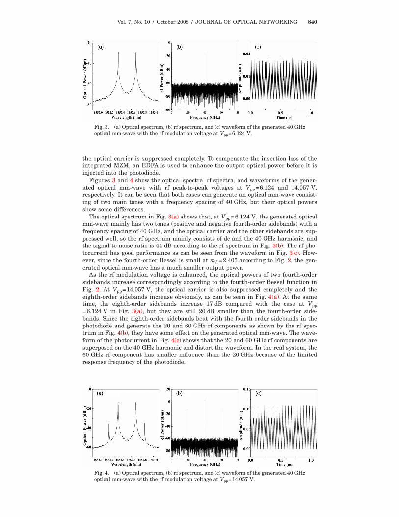
Figures 3 and 4 show the optical spectra, rf spectra, and waveforms of the gener-ated optical mm-wave with rf peak-to-peak voltages at Vpp=6.124 and 14.057 V,respectively. It can be seen that both cases can generate an optical mm-wave consist-ing of two main tones with a frequency spacing of 40 GHz, but their optical powersshow some differences.
The optical spectrum in Fig. 3(a) shows that, at Vpp=6.124 V, the generated opticalmm-wave mainly has two tones (positive and negative fourth-order sidebands) with afrequency spacing of 40 GHz, and the optical carrier and the other sidebands are sup-pressed well, so the rf spectrum mainly consists of dc and the 40 GHz harmonic, andthe signal-to-noise ratio is 44 dB according to the rf spectrum in Fig. 3(b). The rf pho-tocurrent has good performance as can be seen from the waveform in Fig. 3(c). How-ever, since the fourth-order Bessel is small at mh=2.405 according to Fig. 2, the gen-erated optical mm-wave has a much smaller output power.
As the rf modulation voltage is enhanced, the optical powers of two fourth-ordersidebands increase correspondingly according to the fourth-order Bessel function inFig. 2. At Vpp=14.057 V, the optical carrier is also suppressed completely and theeighth-order sidebands increase obviously, as can be seen in Fig. 4(a). At the sametime, the eighth-order sidebands increase 17 dB compared with the case at Vpp=6.124 V in Fig. 3(a), but they are still 20 dB smaller than the fourth-order side-bands. Since the eighth-order sidebands beat with the fourth-order sidebands in thephotodiode and generate the 20 and 60 GHz rf components as shown by the rf spec-trum in Fig. 4(b), they have some effect on the generated optical mm-wave. The wave-form of the photocurrent in Fig. 4(c) shows that the 20 and 60 GHz rf components aresuperposed on the 40 GHz harmonic and distort the waveform. In the real system, the60 GHz rf component has smaller influence than the 20 GHz because of the limitedresponse frequency of the photodiode.
Fig. 3. (a) Optical spectrum, (b) rf spectrum, and (c) waveform of the generated 40 GHzoptical mm-wave with the rf modulation voltage at Vpp=6.124 V.
Fig. 4. (a) Optical spectrum, (b) rf spectrum, and (c) waveform of the generated 40 GHzoptical mm-wave with the rf modulation voltage at V =14.057 V.
pp
Vol. 7, No. 10 / October 2008 / JOURNAL OF OPTICAL NETWORKING 841
4. Analysis and DiscussionThe theoretical deduction and simulation above are based on the assumption that theY branches of the two sub-MZMs have a much higher extinction ratio ��=0.5�. In fact,the extinction ratio is usually limited to approximately 20 dB, which means that ��0.45. In addition, the two arms of the main MZ construction may be imbalanced andthere is a length difference of �L between the two arms. The length difference willlead to the phase imbalance between the two beams output from the two parallelMZMs with =2�n�L /; here n is the refractive index of the waveguide of MZMs and is the wavelength of the lightwave. The limited extinction ratio and phase imbal-ance of the two arms will cause the degradation of the generated optical mm-wave.
If the limited extinction ratio and phase imbalance of the two arms are considered,the mm-wave generated by our scheme can be expressed as
E�t� = �E0 ej�ct����1 exp�j�Vrf cos �mt
V�a� + �1 − �1�exp�− j�
Vrf cos �mt
V�a��ej + �1 − ��
���2 exp�j�Vrf cos��mt + �/2�
V�b�ej + �1 − �2�exp�− j�
Vrf cos��mt + �/2�
V�b���
= �E0 ej�ct ��1 ejmh cos �mt + �1 − �1�e−jmh cos �mtej + �1 − ���2 e−jmh sin �mt
Here we assume that the Y branch of the main MZM has a splitting ratio of �, and theY branches of the two sub-MZMs have splitting ratios of �1 and �2, respectively. It canbe seen that Eq. (4) becomes Eq. (1) when �=�1=�2=0.5 and =0, where the �4m+1�th-, �4m+2�th-, and �4m+3�th-order sidebands are cancelled completely. However,the deviation of the ideal values causes the reduction of the amplitude of the4mth-order sidebands and the appearance of the �4m+1�th-, �4m+2�th-, and �4m+3�th-order sidebands. Their amplitudes depend on the splitting ratios as well as thephase imbalance. We will discuss them in detail below.
For the 4mth -order sideband, its amplitude can be expressed as
�A4m� = �1 + 2�2 − 2� + 2��1 − ��cos , �6�
which is related to the optical splitting ratio ��� of the main MZ and the phase imbal-ance �� between its two arms, but is independent of �1 and �2, as shown in Fig. 5.When the two arms have no phase imbalance �=0�, the amplitude of the 4mth-ordersideband is independent of �; namely, the deviation of the optical splitting ratio from0.5 does not cause the amplitude of the 4mth-order sideband to decrease. However,with the increase of the phase imbalance until =90°, the amplitude of the
Vol. 7, No. 10 / October 2008 / JOURNAL OF OPTICAL NETWORKING 842
4mth-order sideband decreases and becomes more dependent on the optical splittingratio simultaneously. When �=0.5, the amplitude of the 4mth-order sidebanddecreases the worst with the increase of the phase imbalance. From the analysisabove, it can be seen that the phase imbalance �� has greater influence on the ampli-tude of the 4mth-order sideband than the optical splitting ratio ��� does.
The amplitude of the �4m+1�th-order sideband can be expressed as
According to Eq. (7), when �1=�2=0.5, the �4m+1�th-order sideband will be sup-pressed completely in spite of the value of � and ��. If �1 and �2 deviate from 0.5, the�4m+1�th-order sideband will appear, and its amplitude depends on the nested MZMparameters as shown in Fig. 6. Figure 6(a) shows that the two sub-MZMs with a
Fig. 5. Influence of the optical splitting ratio ��� and the phase imbalance �� on the amplitudeof the 4mth-order sideband of the generated optical mm-wave.
Fig. 6. Amplitude of the �4m+1�th-order sideband versus the parameters �, �1, �2,and .
Vol. 7, No. 10 / October 2008 / JOURNAL OF OPTICAL NETWORKING 843
20 dB extinction ratio ��1,2=0.45� cause the �4m+1�th-order sideband to be unable tobe suppressed, and its amplitude varies with � and . Of course, the vestigial�4m+1�th-order sideband gets the minimal amplitude as �=0.5 and =0. From Figs.6(b)–6(d), it can be seen that the amplitude �Am+1� is sensitive to �1 and �2, but thevariation is relatively small when the extinction ratio is limited to within 20 dB. Thiscan be realized easily in the real system. Therefore, if the optical splitting ratios �, �1,and �2 are limited near 0.5, the vestigial �4m+1�th-order sideband can be suppressedto be a much smaller amplitude even if the phase between the two arms is imbal-anced.
The amplitude of the vestigial �4m+2�th-order sideband can be expressed as
�A4m+2� = �1 + 2�2 − 2� − 2��1 − ��cos . �8�
It can be seen that �A4m+2� is sensitive to the splitting ratio ��� and the phase imbal-ance ��, as shown in Fig. 7. When �=0.5 and =0, the �4m+2�th-order sideband issuppressed completely. However, a slight deviation of these values will cause the ves-tigial amplitude to increase obviously. Therefore, to suppress the �4m+2�th-order side-band, the main MZM is required to be of more symmetrical construction.
The amplitude of the �4m+3�th-order sideband can be expressed as
The amplitude of the �4m+3�th-order sideband �A4m+3� is related with the opticalsplitting ratio (�, �1, and �2) and the phase imbalance �� between the two arms, asshown in Fig. 8. When the optical splitting ratios are close to 0.5, the vestigial ampli-tude of the �4m+3�th-order sideband is smaller than 0.1. Although the phase imbal-ance can vary the vestigial amplitude of the �4m+3�th-order sideband, it does notworsen the case obviously. The sideband can be suppressed completely when theparameters are chosen properly, as can be observed in Fig. 8.
From the analysis above, we find that (1) the amplitude of the 4mth-order sidebandis related to the optical splitting ratio ��� and the phase imbalance �� of the mainMZM. The deviation of their ideal values will reduce the amplitude of the 4mth-ordersideband. (2) Although the amplitude of the �4m+2�th-order sideband is not related tothe optical splitting ratio �1 and �2 of the two sub-MZMs, it is very sensitive to � and��. The deviation of �=0.5 and =0 will cause an obvious vestigial amplitude. (3)Although the amplitude of the �4m+1�th- and �4m+3�th-order sideband is related tothe optical splitting ratios �, �1, �2, and ��, they have much smaller amplitudes whenthe optical splitting ratios are close to the ideal value (0.5). In this case, the phaseimbalance �� has little effect on the vestigial amplitudes. Thus, although the idealcase is difficult to implement in practice, the slight deviation of the ideal values of thenested MZM will never cause great degradation of the generated optical mm-wave.
Fig. 7. Amplitude of the �4m+2�th-order sideband versus the parameters � and ��.
Vol. 7, No. 10 / October 2008 / JOURNAL OF OPTICAL NETWORKING 844
5. ConclusionThis paper proposes what we believe to be a novel scheme to generate an opticalmm-wave with octupling of the local oscillator via a nested LiNbO3 Mach–Zehndermodulator with a lower response frequency. According to the theoretical analysis onthe characteristics of the modulator, an optical mm-wave with frequency octupling ofthe local oscillator can be generated by properly adjusting its dc bias voltages and thelocal oscillator voltages and phases. The simulation results show the generated opticalmm-waves at two different modulation depths. When the modulation index is mh=2.405, the generated optical mm-wave has a much purer spectrum while its power issmaller. As the modulation index is increased to mh=5.52, the power of the opticalmm-wave increases greatly, but its spectral purity is degraded to some degree. Sincethe scheme realizes the frequency eightfold as the local oscillator is modulated on theoptical carrier, the scheme largely reduces the response frequency of the modulatorand the local oscillator frequency. The analysis of the optical splitting ratio and thephase imbalance of the nested MZM show that the performance of the generated opti-cal mm-wave does not degrade obviously even if the parameters of the nested MZMdeviate away from the ideal values to some degree.
AcknowledgmentsThis research was supported partly by the National High Technology Research andDevelopment Program of China (863 program, 2007AA01Z263), the Key Project of theChinese Ministry of Education (107011), and the Teaching and Scientific ResearchFoundation for the Returned Overseas Chinese Scholars, Ministry of Education.
References1. B. Lannoo, D. Colle, M. Pickavet, and P. Demeester, “Radio-over-fiber-based solution to
provide broadband internet access to train passengers,” IEEE Commun. Mag. 45(2), 56–62(2007).
2. G.-K. Chang, Z. Jia, J. Yu, A. Chowdhury, T. Wang, and G. Ellinas, “Super-broadbandoptical wireless access technologies,” in Optical Fiber Communication Conference andExposition and the National Fiber Optic Engineers Conference, OSA Technical Digest (CD)(Optical Society of America, 2008), paper OThD1.
Fig. 8. Amplitude of the �4m+3�th-order sideband versus the parameters �, �1, �2,and ��.
Vol. 7, No. 10 / October 2008 / JOURNAL OF OPTICAL NETWORKING 845
3. A. M. J. Koonen, M. G. Larrodé, A. Ng’oma, K. Wang, H. Yang, Y. Zheng, and E.Tangdiongga, “Perspectives of radio over fiber technologies,” in Optical FiberCommunication Conference and Exposition and the National Fiber Optic EngineersConference, OSA Technical Digest (CD) (Optical Society of America, 2008), paper OThP3.
4. C. Kim, I. Kim, G. Li, and M. R. Lange, “Optical microwave/millimeter-wave links usingdirect modulation of two-section gain-coupled DFB lasers,” IEEE Photon. Technol. Lett. 17,1734–1736 (2005).
5. Y. Li, M. Bystrom, D. Yoo, S. M. Goldwasser, and P. R. Herczfeld, “Coherent optical vectormodulation for fiber radio using electrooptic microchip lasers,” IEEE Trans. MicrowaveTheory Tech. 53, 3121–3129 (2005).
6. Y. Doi, S. Fukushima, T. Ohno, and K. Yoshino, “Frequency stabilization of millimeter-wavesubcarrier using laser heterodyne source and optical delay line,” IEEE Photon. Technol.Lett. 13, 1002–1004 (2001).
7. J. Yu, Z. Jia, L. Yi, Y. Su, G.-K. Chang, and T. Wang, “Optical millimeter-wave generation orup-conversion using external modulator,” IEEE Photon. Technol. Lett. 18, 265–267 (2006).
8. J. Yu, J. Gu, X. Liu, Z. Jia, and G. K. Chang, “Seamless integration of an 8�2.5 Gb/sWDM-PON and radio-over-fiber using all-optical up-conversion based on Raman-assistedFWM,” IEEE Photon. Technol. Lett. 17, 1986–1988 (2005).
9. T. Schneider, D. Hannover, and M. Junker, “Investigation of Brillouin scattering in opticalfibers for the generation of millimeter waves,” J. Lightwave Technol. 24, 295–304 (2006).
10. J. Ma, C. Yu, Z. Zhou, and J. Yu, “Optical mm-wave generation by using an externalmodulator based on optical carrier suppression,” Opt. Commun. 268, 51–57 (2006).
11. J. Ma, L. Chen, C. Yu, J. Yu, X. Xin, and Z. Dong, “Transmission of 40-GHz opticalmillimeter-wave generated by quadrupling 10-GHz local oscillator via Mach–Zehndermodulator,” (submitted to J. Opt. A, Pure Appl. Opt.).
12. J. Ma, J. Yu, X. Xin, C. Yu, and L. Rao, “A novel scheme to implement duplex 60-GHzradio-over-fiber link with 20-GHz double-sideband optical millimeter-wave transmittedalong the fiber,” Opt. Fiber Technol. (to be published).
13. Q. Wang, H. Rideout, F. Zeng, and J. Yao, “Millimeter-wave frequency tripling based onfour-wave mixing in a semiconductor optical amplifier,” IEEE Photon. Technol. Lett. 18,2460–2462 (2006).
14. C.-T. Lin, P.-T. Shih, J. Chen, W.-Q. Xue, P.-C. Peng, and S. Chi, “Optical millimeter-wavesignal generation using frequency quadrupling technique and no optical filtering,” IEEEPhoton. Technol. Lett. 20, 1027–1029 (2008).