Optical pattern recognition on nonvertical imagery David Casasent and Alan Furman An optical matched spatial filtering system is described that is capable of correlating nonvertical imagery with no loss in the peak intensity and SNR of the output correlation. From the coordinates of the correla- tion peak, the tilt angle of one camera (or angle of approach of the object being photographed) and the scale of the image (distance from the object) can be determined. Experimental demonstrations of the principle (combined geometrical and optical transformations) on actual imagery are included. 1. Introduction Coherent optical correlation has been applied to various image pattern recognition computations for numerous applications. However, the classic and simple forms of such correlators are unable to locate a reference image in an input image (without severe cor- relation losses) when multiple angular distortions are present in the two images. Stereo compilation, by which 3-D measurements are extracted from a stereo pair of photographs, is difficult to automate ' 2 because of the required parallax measurement. Parallax ex- traction involves locating small areas of one stereo image in the other. Many correlation methods 3 - 7 have been investigated to aid such image mapping, but nonvertical imagery and terrain slope distortions remain problems in all automated techniques. In practice, the two images in this stereocompilation case or the input and reference images in the general pattern recognition problem will not be true vertical photographs. The camera will be rotated and/or in- clined at a different angle to the ground for each etc. In photogrammetry, this problem can be overcome by rectification of the imagery (copying it in an oblique plane camera system). The use of epipolar scans 89 is also being tested. The cost and time lag of these oper- ations are undesirable in a final system and require a prior knowledge of the camera orientations or a search of all possible ones. Even with vertical or rectified imagery, correlation still does not proceed unhindered. Any part of the earth's surface not parallel to the line connecting the camera positions will be recorded at different scales (along this one axis) in the two stereo images. Prism The authors are with Carnegie-Mellon University, Department of Electrical Engineering, Pittsburgh, Pennsylvania 15213. Received 11 November 1976. anamorph systems 4 have been used to provide variable magnification in 1-D but such schemes require a motor drive (thus reducing the system's speed) and use a closed-loop control. (This causes the system to stop if correlation is lost.) In this paper we describe an analog optical correlator system that operates on nonvertical imagery (and is hence multiangle tolerant) and is immune to the scale error caused by terrain slope. Other extensions of this scheme to the cases of missile guidance and reentry vehicle identification will be briefly noted in the con- clusion. II. Coordinate Systems Three coordinate systems are involved in this dis- cussion. The coordinates of the earth's surface are represented by (xe,ye). If the (xe,ye) plane is rotated counterclockwise by an angle 01,a (xi,ye') coordinate system results. If this Ye axis is now rotated counter- clockwise by an angle (1i about the +x 1 axis, the second coordinate system of interest (x 1 ,y 1 ) results as shown in Fig. 1. The third coordinate system of concern (x 2 ,y2) is formed as above with different rotational an- gles 02 and 12 used. When an object in the (xe,ye) plane is projected onto the (xl,yl) and (x 2 ,y 2 ) planes, distorted images result as if the original image were recorded by two cameras pointed at the origin of the (xe,Ye) plane but with their optical axes normal to the (xl,yl) and (X2, Y2) planes. The coordinates of points projected onto these oblique planes are related to their original (xe,Ye) coordinates by transformation matrices T 1 and T 1 as ['] = T [], [ 2] = T [ ], (la) (lb) where July 1977 / Vol. 16, No. 7 / APPLIED OPTICS 1955
Transcript
Optical pattern recognition on nonvertical imagery
David Casasent and Alan Furman
An optical matched spatial filtering system is described that is capable of correlating nonvertical imagery
with no loss in the peak intensity and SNR of the output correlation. From the coordinates of the correla-tion peak, the tilt angle of one camera (or angle of approach of the object being photographed) and the scale
of the image (distance from the object) can be determined. Experimental demonstrations of the principle(combined geometrical and optical transformations) on actual imagery are included.
1. Introduction
Coherent optical correlation has been applied tovarious image pattern recognition computations fornumerous applications. However, the classic andsimple forms of such correlators are unable to locate areference image in an input image (without severe cor-relation losses) when multiple angular distortions arepresent in the two images. Stereo compilation, bywhich 3-D measurements are extracted from a stereopair of photographs, is difficult to automate ' 2 becauseof the required parallax measurement. Parallax ex-traction involves locating small areas of one stereo imagein the other. Many correlation methods3-7 have beeninvestigated to aid such image mapping, but nonverticalimagery and terrain slope distortions remain problemsin all automated techniques.
In practice, the two images in this stereocompilationcase or the input and reference images in the generalpattern recognition problem will not be true verticalphotographs. The camera will be rotated and/or in-clined at a different angle to the ground for each etc. Inphotogrammetry, this problem can be overcome byrectification of the imagery (copying it in an obliqueplane camera system). The use of epipolar scans8 9 isalso being tested. The cost and time lag of these oper-ations are undesirable in a final system and require aprior knowledge of the camera orientations or a searchof all possible ones.
Even with vertical or rectified imagery, correlationstill does not proceed unhindered. Any part of theearth's surface not parallel to the line connecting thecamera positions will be recorded at different scales(along this one axis) in the two stereo images. Prism
The authors are with Carnegie-Mellon University, Department ofElectrical Engineering, Pittsburgh, Pennsylvania 15213.
Received 11 November 1976.
anamorph systems4 have been used to provide variablemagnification in 1-D but such schemes require a motordrive (thus reducing the system's speed) and use aclosed-loop control. (This causes the system to stop ifcorrelation is lost.)
In this paper we describe an analog optical correlatorsystem that operates on nonvertical imagery (and ishence multiangle tolerant) and is immune to the scaleerror caused by terrain slope. Other extensions of thisscheme to the cases of missile guidance and reentryvehicle identification will be briefly noted in the con-clusion.
II. Coordinate Systems
Three coordinate systems are involved in this dis-cussion. The coordinates of the earth's surface arerepresented by (xe,ye). If the (xe,ye) plane is rotatedcounterclockwise by an angle 01, a (xi,ye') coordinatesystem results. If this Ye axis is now rotated counter-clockwise by an angle (1i about the +x 1 axis, the secondcoordinate system of interest (x1 ,y1 ) results as shownin Fig. 1. The third coordinate system of concern(x2,y2) is formed as above with different rotational an-gles 02 and 12 used.
When an object in the (xe,ye) plane is projected ontothe (xl,yl) and (x2,y2) planes, distorted images resultas if the original image were recorded by two cameraspointed at the origin of the (xe,Ye) plane but with theiroptical axes normal to the (xl,yl) and (X2, Y2) planes.The coordinates of points projected onto these obliqueplanes are related to their original (xe,Ye) coordinatesby transformation matrices T1 and T1 as
['] = T [],
[ 2] = T [ ],
(la)
(lb)
where
July 1977 / Vol. 16, No. 7 / APPLIED OPTICS 1955
[ ao]TD = aLobI
and
T3 = (1/M) TDTlT 2-'.
z.
X0,-11 Y.IX.
Fig. 1. Geometrical relationship between earth coordinate, (XeYe)and tilted and rotated camera axes coordinate systems.
= cosOiL -sinO0 cosTI
sin 1 ]coso1 cos4 II
T [ CO 2 co sinO2 ] (2b)
The case of unequal camera heights can be accountedfor by applying a scalar magnification factor M to the(x2,y2) coordinates yielding
[ ] M[X2] ()IY2m Y2 3
This is analogous to a scale change in the image. If thefocal lengths of the cameras from which the two imageswere taken are equal to f and the cameras are at eleva-tions h and h2 >> f, then M = h/h 2 in Eq. (3).
III. Correlation Procedure
A correlation procedure will now be described bywhich these two distorted images (with distortionscharacterized by 01, 02, 01, 02, and M) can be orrelatedwith no loss in signal-to-noise ratio (SNR) of the cor-relation and without the need for multiple MSFs. *Asa simplified initial case to demonstrate the procedure,we assume that the difference between the rotationangles A0 O - 0 and the tilt angle 02 of one cameraare known. Such a situation could correspond to thecase when one image was rectified.
The first step in the correlation is the application ofa linear transformation T3 to the (X2m,Y2m) coordinateimage. This produces
[X2m] = [(4)
Y2m Y3where the coordinate systems (x3y3) and (xl,yl) arerelated by
[3] = TD []
TD is a diagonalized matrix
(5)
(7)
An image in ( 3 ,y3) coordinates will now be identicalto an image in (xl,y,) coordinates, except for scale dif-ferences a and b along the two axes. The problem nowreduces to determining the transformation matrix T3.If we set a = M and b = MICl, we find
T cosAO sinAO 1 0 1L -sinAO cosA0O L0 1/C2 (
The inverse matrix T2 -1 always exists, except for thetrivial case of k02 -7r/2 corresponding to an image takenfrom the horizon. All terms in the transformationmatrix described by Eq. (8) are known. This trans-formation corresponds to an expansion of the x 2 axis by(cos02)-l to compensate for the tilt error and a rotationby AO by which the x and X2 axes are aligned. Thecoordinates of the two resultant images are now relatedby
[x3] = [M MC] [] (9)
corresponding to a scaling of x by M and a scaling ofY2 proportional to M and (cosbl)-'.
IV. Mellin Traiisforms
Since the axes of these new images are related by scalefactors, the newly eported optical Mellin transforml1 'llcan be used to correlate these images. This correlationcan be realized with no loss in the peak intensity (Ip) orSNR from the ideal autocorrelation case.'0 Of moreimportance i the present case is the fact that thecoordinates of the correlation peak are proportional tothe scale differences along the two axes.12 ,13
As a brief review of optical Mellin transforms, we notethat the Mellin transform M(u) of f(x) is defined in 1-Dfor simplicity only by
M(u) = f(x)x-jU-ldx
= f f(expt) exp(-jut)d4.f <_
(1Oa)
(lOb)
From Eq. (Ob), we see that the Fourier transform off(expt) is the Mellin transform of f(x). This formula-tion is vital to the optical implementation of this oper-ation since the Fourier transform is easily produced bya lens.
The Melliti transforms Ml and M2 of two scaledfunctions f = f(x) and 2 = f (ax) are related by
M2 (u) = a-iUMI(u) = bxp(-ju Ina)Mi(u), (11)
from which we see that IMlI = M21. If f (expt) isrecorded in the input plane Po and M2* in the filterplane P, of the classical optical correlator of Fig. 2, theterm of interest in the light distribution leaving P is
MlM2* = Mj(u)Mi(u) exp(ju Ina). (12)
The corresponding term in the output plane P2 is theFourier transform of Eq. (12) or
Po is the input plane, P1 the MSF plane, and P 2 the output correlationplane.
12
8
Y.
4
00 4 8 12
Xe
U(x2,y2) = fiofi * d(x 2 - lna), (13)
when 0 denotes correlation and * convolution. FromEq. (13) we see that the magnitude of the cross-corre-lation of f/ and f2 is identical to the autocorrelation of[l and that the location of the correlation peak is pro-portional to the scale change between the two func-tions.
We denote the two input images with coordinates(xiyi) and (X2m,Y2m) as t1 and t2m, respectively. Theresultant image, after application of the transformationT3 to the coordinates of t2 , is denoted by t 3. We pro-pose to apply Mellin transform correlation techniquesto t1 and t3 by logarithmically scaling the coordinatesof each image to produce the new images gi and g3.When these two images are correlated, the coordinatesof the resultant correlation peak will be proportional toM and M/C1, respectively. Thus, the scale and tiltdistortions between the imagery can be obtained.
y. Experimental Results (Input Line prawini s)
The two images in Fig. 3 are representative examplesof a rectangle with the nonvertical image distortionsdescribed in Sec. II present. Figure 3(a) correspondsto tl(xl,yl) and Fig. 3(b) to t2m(X2m,Y2m). The dis-tortions are characterized by 01 = -3, 02 = 14°, AO =170, 01 = 100, and ')2 200 and a 0% magnificationfactor M = 1.3. The basic optical correlator for non-vertical image correlation is shown in general form inFig. 4. It contains a coordinate transformation prep-rocessing section in which the linear transformation T3
is performed to convert t2m(X2,Y2) to t 3 (x3 ,y3) and inwhich the coordinates qf t1 and t 3 are logarithmicallyscaled. This latter step produces the two functions g,and g3:
qjlxo,yo) = t(ex9,eYo),
g3(xoyo) = t3(exoeYo),(a)
(14a)
(14b)
which are used as inputs at plane Po of the conventionaloptical correlator shown in the remainder of Fig. 4. Therequired logarithmic scaling and linear transformationare easily implemented by modifying the sweep rampsof a TV camera and monitor from which the g1 and g3transparencies were photographed.
FlEPICESII
X2m
(b)
Fig. 3. Input line drawings of simulated nonvertical input imagery.
Images Xl (a) and X2 m (b) have 01 = -39, 02 = 20°, A0 = 17°, 'l =10°, F2 = 20°, and M = 1.3.
f (X,.)
LIEI IfI T
P L P l L2 P20 2
Fig. 4. Simplified schematic of space variant processor for nonver-
tical imagery.
July 1977 / yol. 16, No. 7 / APPLIED OPTICS 1957
12
8
Y2m
4
00 4 8
�_ f - 1 s f --1 - f - I f -4
I I
l
lOdB1MM
i
Fig. 5. Cross-sectional scans of the autocorrelation of Xi and thecross-correlation of Xi and X2m showing no correlation loss and adisplacement of the correlation peak by an amount proportional to
the scale change along the axis scanned.
Fig. 6. Output cross-correlation plane pattern at P2 of Fig. 4 for theimagery of Fig. 3.
With g present at Po, its Fourier transform G1, whichis also the Mellin transform of t, is produced by lensLl at plane Pl. Here it is interfered with a plane wavereference beam, and G and other terms are recordedholographically. With this filter function G* presentat P and g in place at P, the autocorrelation of g,appears at P2. The cross-sectional plot of this auto-correlation (taken with a scanning radiometric micro-scope) is shown in the upper portion of Fig. 5. With thematched spatial filter G* in place at P and g3 presentat Po, the cross-correlation of g and g3 (shown in Fig.6) appears at P2. The cross-sectional scan of thiscross-correlation peak is shown in the lower portion ofFig. 5. A comparison shows that the peak intensity andSNR of the autocorrelation and cross-correlations areidentical as predicted by Eq. (13) and that the positionof the correlation peak in the bottom portion of Fig. 5has shifted from its position in the top portion of Fig.5. The amount of shift was calculated to be propor-tional to the magnification M between the images aspredicted by Eq. (13). The cross-sectional scans of theautocorrelations and cross-correlations in the orthog-onal direction also show a displacement in the locationof the correlation peak with the shift now proportionalto M/C1 as predicted.
VI. Experimental Results-Aerial ImageryTo demonstrate the application of these techniques
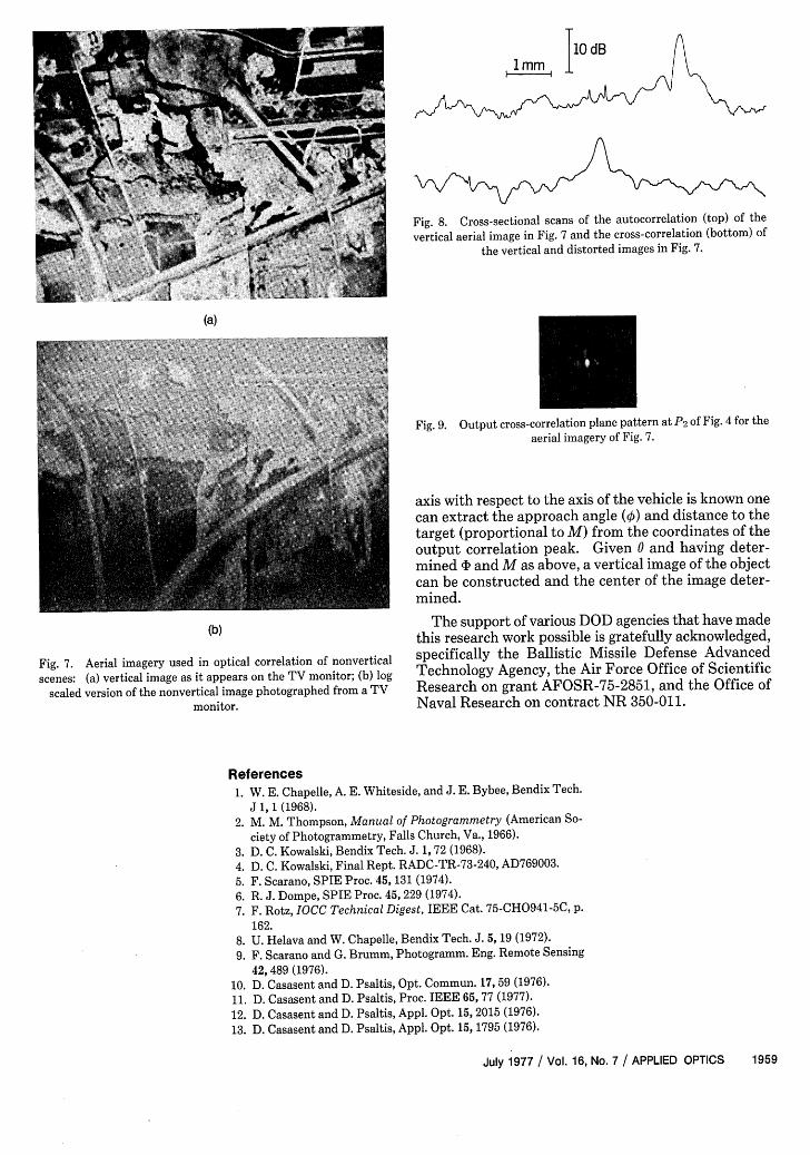
on actual aerial imagery and as the first published re-sults of the use of Mellin transform correlation tech-niques on an actual image, a brief experiment was per-formed. An aerial photograph of a portion of Hunts-ville, Alabama was imaged onto a TV camera with thecamera oriented normal to the photograph. The pho-tograph was then tilted by 30 with respect to the normalto the camera to simulate a 13% (cos3O0 = 0.87) scalechange distortion in the image due to camera tilt.
In this demonstration, the input transparencies g1and 92m (the log-scaled versions of the original imagest1 and t2m) were obtained from photographs of thedisplay on a TV monitor with logarithmic scan circuitry.A photograph of the vertical image t1 as it would appearon the monitor (with normal sweep signals) is shown inFig. 7(a). The g2 ,m version of the scaled/tilted image asit actually appeared on the monitor is shown in Fig.7(b).
With g placed at Po of Fig. 4, its conjugate Fouriertransform G* (the conjugate Mellin transform of t1 )is recorded at P1 as before. With g1 still present at Po,the autocorrelation of the vertical image appears at P2.(Its cross-sectional scan is shown in the upper plot inFig. 8.) With g2 present at Po, the cross-correlation(Fig. 9) of the vertical and nonvertical (scaled and tilted)images appears at P2 . As before and as shown in thecross-sectional scan in the lower trace in Fig. 8, the peakintensity and SNR of the autocorrelations and cross-correlations are again equal, and the location of thecorrelation peak has shifted by an amount proportionalto the 13% scale change present between the input im-ages. Thus the scale factor, effective terrain relief,parallax, and camera tilt angle for nonvertical imagerycan be obtained from the coordinates of the correlationpeak.
All the log and linear transformations noted in theseexamples can easily be achieved on real-time spatiallight modulators as noted elsewhere.
VII. Conclusion and Summary
An extension of the use of Mellin transforms to ap-plications in stereocompilation (parallax determina-tion), correlation of nonvertical imagery, missile guid-ance, and identification of reentry vehicles has beendemonstrated. These experimental results also includethe first reported results of Mellin transform correlationtechniques on actual aerial imagery.
In the general case, the problem addressed can bestated as the need to determine the coordinates of thecenter of an image with respect to a fixed referenceplane. Such data are the key elements in a missileguidance system based on correlations of reference andstored imagery. When the camera tilt and rotation aswell as the terrain relief and hence the effective scale ofthe imagery in 1-D differ between the reference andinput, the methods advanced in this paper are appro-priate. The distances from the object and the approachangle of the vehicle or missile are usually desired. Asdemonstrated herein, if the azimuth of the scanner's
1958 APPLIED OPTICS / Vol. 16, No. 7 / July 1977
T10 dBI mm 1
Fig. . Cross-sectional scans of the autocorrelation (top) of the
vertical aerial image in Fig. 7 and the cross-correlation (bottom) ofthe vertical and distorted images in Fig. 7.
(a)
FiPg. 9. Output cross-correlation plane pattern at P2 of Fig. 4 for theaerial imagery of Fig. 7.
axis with respect to the axis of the vehicle is known onecan extract the approach angle (k5) and distance to thetarget (proportional to M) from the coordinates of theoutput correlation peak. Given 0 and having deter-mined 1' and M as above, a vertical image of the objectcan be constructed and the center of the image deter-mined.
(b) The support of various DOD agencies that have madethis research work possible is gratefully acknowledged,
Fig. 7. Aerial imagery used in optical correlation of nonvertical specifically the Ballistic Missile Defense Advanced
scenes: (a) vertical image as it appears on the TV monitor; (b) log Technology Agency, the Air Force Office of Scientific
scaled version of the nonvertical image photographed from a TV Research on grant AFOSR-75-2851, and the Office ofmonitor. Naval Research on contract NR 350-011.
References1. W. E. Chapelle, A. E. Whiteside, and J. E. Bybee, Bendix Tech.
J 1, 1 (1968).2. M. M. Thompson, Manual of Photogrammetry (American So-
ciety of Photogrammetry, Falls Church, Va., 1966).
3. D. C. Kowalski, Bendix Tech. J. 1, 72 (1968).
4. D. C. Kowalski, Final Rept. RADC-TR-73-240, AD769003.
5. F. Scarano, SPIE Proc. 45, 131 (1974).6. R. J. Dompe, SPIE Proc. 45, 229 (1974).
7. F. Rotz, IOCC Technical Digest, IEEE Cat. 75-CH0941-5C, p.162.
8. U. Helava and W. Chapelle, Bendix Tech. J. 5, 19 (1972).
9. F. Scarano and G. Brumm, Photogramm. Eng. Remote Sensing
42, 489 (1976).10. D. Casasent and D. Psaltis, Opt. Commun. 17, 59 (1976).
11. D. Casasent and D. Psaltis, Proc. IEEE 65, 77 (1977).
12. D. Casasent and D. Psaltis, Appl. Opt. 15, 2015 (1976).
13. D. Casasent and D. Psaltis, Appl. Opt. 15, 1795 (1976).