Optical phase conjugation in phase-modulated transmission systems: experimental comparison of different nonlinearity-compensation methods
Paolo Minzioni,1,*
Vincenzo Pusino,1 Ilaria Cristiani,
1 Lucia Marazzi,
2,3
Mario Martinelli3 Carsten Langrock,
4 M. M. Fejer,
4 and Vittorio Degiorgio
1
1CNISM and Electronics dept., University of Pavia, Via Ferrata 1, 27100 Pavia Italy 2Fondazione Politecnico di Milano, piazza Leonardo da Vinci 32, 20133 Milan, Italy
3 PoliCom Dept. of Electronics and Information, Politecnico di Milano, via Ponzio, 32, 20133 Milan, Italy 4Edward L. Ginzton Laboratory, Stanford University, 450 Via Palou, 94305 Stanford, CA, USA
Abstract: We experimentally compare the effectiveness of three different optical-phase-conjugation-based nonlinearity-compensation strategies on a transmission system employing phase-modulated signals, and hence affected by the Gordon-Mollenauer effect. We demonstrate that it is possible to obtain significant nonlinearity compensation, but that no improvement is obtained using configurations specifically aimed at the compensation of the nonlinear phase noise.
1. C. R. S. Fludger, T. Duthel, C. Schulien, “Towards Robust 100G Ethernet Transmission” Proceeding LEOS Summer Topical Meetings 2007 Digest of the IEEE, 224–225 (2007).
2. P. J. Winzer, and R.-J. Essiambre, “Advanced optical modulation formats,” Proc. IEEE 94(5), 952–985 (2006). 3. J. P. Gordon, and L. F. Mollenauer, “Phase noise in photonic communications systems using linear amplifiers,”
Opt. Lett. 15(23), 1351–1353 (1990). 4. E. Ip, and J. M. Kahn, “Digital equalization of chromatic dispersion and polarization mode dispersion,” J.
Lightwave Technol. 25(8), 2033–2043 (2007). 5. W. Pieper, C. Kurtzke, R. Schnabel, D. Breuer, R. Ludwig, K. Petermann, and H. Weber, “Nonlinearity-
insensitive standard-fibre transmission based on optical-phase conjugation in a semiconductor-laser amplifier,” Electron. Lett. 30(9), 724–725 (1994).
6. S. Watanabe, and T. Chikama, “Cancellation of four-wave mixing in multichannel fibre transmission by midway optical phase conjugation,” Electron. Lett. 30(14), 1156–1157 (1994).
7. C. Lorattanasane, and K. Kikuchi, “Design theory of long-distance optical transmission systems using midway optical phase conjugation,” J. Lightwave Technol. 15(6), 948–955 (1997).
8. P. Minzioni, I. Cristiani, V. Degiorgio, L. Marazzi, M. Martinelli, C. Langrock, and M. M. Fejer, “Experimental Demonstration of Nonlinearity and Dispersion Compensation in an Embedded Link by Optical Phase Conjugation,” IEEE Photon. Technol. Lett. 18(9), 995–997 (2006).
9. P. Minzioni, “Nonlinearity Compensation in a Fiber-Optic Link by Optical Phase Conjugation,” Fiber Integr. Opt. 28(3), 179–209 (2009).
10. C. J. McKinstrie, S. Radic, and C. Xie, “Reduction of Soliton Phase Jitter by In-Line Phase Conjugation,” Opt. Lett. 28(17), 1519–1521 (2003).
11. S. L. Jansen, D. van den Borne, C. C. Monsalve, S. Spalter, P. M. Krummrich, G. D. Khoe, and H. de Waardt, “Reduction of Gordon-Mollenauer phase noise by mid-link spectral inversion,” IEEE Photon. Technol. Lett. 17(4), 923–925 (2005).
12. S. L. Jansen, D. van den Borne, B. Spinnler, S. Calabrò, H. Suche, P. M. Krummrich, W. Sohler, G. D. Khoe, and H. de Waardt, “Optical phase conjugation for ultra long-haul phaseshift-keyed transmission,” J. Lightwave Technol. 24(1), 54–64 (2006).
13. P. Minzioni, V. Pusino, I. Cristiani, L. Marazzi, M. Martinelli, and V. Degiorgio, “Study of the Gordon-Mollenauer Effect and of the Optical-Phase-Conjugation Compensation Method in Phase-Modulated Optical Communication Systems,” IEEE Photon. J. 2(3), 284–291 (2010).
14. G. P. Banfi, P. K. Datta, V. Degiorgio, and D. Fortusini, “Wavelength shifting and amplification of optical pulses through cascaded second-order processes in periodically poled lithium niobate,” Appl. Phys. Lett. 73(2), 136–138 (1998).
#127353 - $15.00 USD Received 27 Apr 2010; revised 10 Jun 2010; accepted 8 Jul 2010; published 9 Aug 2010(C) 2010 OSA 16 August 2010 / Vol. 18, No. 17 / OPTICS EXPRESS 18119
15. M. H. Chou, J. Hauden, M. A. Arbore, and M. M. Fejer, “1.5-µm-band wavelength conversion based on difference frequency generation in LiNbO3 waveguides with integrated coupling structures,” Opt. Lett. 23(13), 1004–1006 (1998).
16. M. L. Bortz, and M. M. Fejer, “Annealed proton-exchanged LiNbO3 waveguides,” Opt. Lett. 16(23), 1844–1846 (1991).
17. C. Langrock, S. Kumar, J. E. McGeehan, A. E. Willner, and M. M. Fejer, “All-Optical Signal Processing Using χ2 Nonlinearities in Guided-Wave Devices,” J. Lightwave Technol. 24(7), 2579–2592 (2006).
18. T. Hasegawa, K. Inoue, and K. Oda, “Polarization independent frequency conversion by fiber four-wave mixing with a polarization diversity technique” IEEE Photon, Technol. Lett. 5(8), 947–949 (1993).
19. P. Martelli, P. Boffi, M. Ferrario, L. Marazzi, P. Parolari, R. Siano, V. Pusino, P. Minzioni, I. Cristiani, C. Langrock, M. M. Fejer, M. Martinelli, and V. Degiorgio, “All-Optical Wavelength Conversion of a 100-Gb/s Polarization-Multiplexed Signal,” Opt. Express 17(20), 17758–17763 (2009).
20. S. L. Jansen, S. Spalter, G. D. Khoe, H. de Waardt, H. E. Escobar, L. Marshall, and M. Sher, “6x40 gb/s over 800 km of SSMF using mid-link spectral inversion,” IEEE Photon. Technol. Lett. 16(7), 1763–1765 (2004).
21. P. Minzioni, and A. Schiffini, “Unifying theory of compensation techniques for intrachannel nonlinear effects,” Opt. Express 13(21), 8460–8468 (2005).
22. L. Marazzi, P. Parolari, P. Martelli, A. Gatto, M. Martinelli, P. Minzioni, I. Cristiani, V. Degiorgio, “Impact of OPC insertion in a WDM link”, CLEO Europe 2007, paper CI_17 (2007).
1. Introduction
The next generation of optical transmission systems will require significant changes in the link structure and operation [1]. In particular, one of the most crucial changes, required to enable the transmission of high-capacity channels (exceeding 80 Gb/s), is the transition from amplitude-modulation to phase-modulation formats exploiting multi-level encoding techniques. Fiber-optic nonlinearities, such as Kerr nonlinearities, are the main sources of impairment in very high-bit-rate transmission systems. Kerr nonlinearities induce an intensity dependent, and hence time-varying, phase-shift, which leads to the generation of new frequency components in the signal spectrum. The interplay between the new frequencies and the fiber chromatic dispersion produces a signal distortion that can strongly affect the signal quality. The use of constant-power phase-modulation formats could help to reduce the distortions induced by fiber dispersion and nonlinearities [2]. However, fiber dispersion produces a change in the temporal shape of the signal, giving rise to peaks and valleys in the signal amplitude. Moreover, fiber nonlinearities cause an additional source of nonlinear impairment: the so called “Gordon-Mollenauer” (GM) effect, or “nonlinear phase noise” [3], which is due to the nonlinear interplay between the signal and the amplified spontaneous emission (ASE) from in-line amplifiers. Indeed, ASE adds linearly to the signal, leading to amplitude noise that is converted to phase noise through self-phase modulation, in this way affecting the performance of phase-modulated (PM) systems. A very interesting technique for correcting signal distortions is the electronic post-processing of the received signal, but its applicability to nonlinearity compensation is still quite limited, as the nonlinearity impact also strongly depends on the transmitted data pattern and on the evolution of the optical signal along the whole transmission link [4].
Compensation methods based on optical phase conjugation (OPC) are very attractive because they work in real time and promise to be transparent to the modulation format. They have already been successfully tested on transmission links based on OOK modulation formats, by using either the classical mid-span spectral-inversion (MSSI) approach [5–7] or, more recently, the mid-nonlinearity temporal-inversion (MNTI) approach [8, 9]. For the case of PM systems, OPC-compensation methods are discussed in Refs. [10–12]. In particular, the analysis described in [10], based on the assumption that the signal distortion is mainly due to the GM effect, prescribes to put the OPC-device at 2/3 of the total link length. In the following, we will call this approach Gordon-Mollenauer compensation (GMC). An intuitive view of this approach, which can be applied also to non soliton-based systems, is given in Ref. 9. A recent detailed simulation [13] shows that GM noise is not the main source of impairment in realistic PM links, so that the methods devised for amplitude-modulated systems should be applicable to PM systems as well. It is therefore of utmost importance to experimentally test the theoretical predictions in order to clarify the relevance of the GM
#127353 - $15.00 USD Received 27 Apr 2010; revised 10 Jun 2010; accepted 8 Jul 2010; published 9 Aug 2010(C) 2010 OSA 16 August 2010 / Vol. 18, No. 17 / OPTICS EXPRESS 18120
effect and to assess the optimal configuration for high-bit-rate phase-modulated optical communication systems.
In this paper, we present a set of experimental results concerning the OPC-compensation of signal distortions in transmission systems using differential phase shift keying modulation (DPSK) both on non-return to zero (NRZ) and return-to-zero (RZ) signals. We have tested three different methods, GMC, MSSI and MNTI, and compared their performance in terms of the measured bit error rate versus signal power. In agreement with the numerical simulations of Ref.13, we find that the best compensation is given by the MNTI method.
2. Experimental setup
The experimental setup is composed of three elements: the opto-electronic interfaces (transmitter/receiver), the transmission line, and the optical phase conjugation setup.
2.1 Transmitter and Receiver
The DPSK transmitter (Tx) used for the experiments includes a dual-arm Mach-Zehnder interferometric modulator driven by twice Vπ, in order to achieve 0-π modulation. To generate an RZ-shaped phase modulated signal (duty cycle 66%), an RZ carver driven by a sinusoidal signal is employed, as shown in Fig. 1, whereas in order to generate NRZ-DPSK signals, the carver is driven by an appropriate (and constant) bias. At the receiver (Rx), the signal is optically amplified and filtered, and a Mach-Zehnder delay interferometer (MZDI) is employed to directly detect the phase modulation. A small portion (5%) of the optical power is tapped in order to perform the clock recovery function, while the rest is detected by a 13-GHz photodetector. To obtain BER versus received power curves, the optical power is varied by means of an optical attenuator. The transmitted pattern is a 2
31-1 bits-long PRBS string.
The transmitted OSNR is higher than 40 dB, while the received OSNR is higher than 25 dB (both OSNR measured with 0.1 nm resolution).
Fig. 1. The setup of employed transmitter and receiver are shown in a) and b) respectively.
2.2 Transmission line
The transmission line has been realized using six spans of non-zero dispersion shifted fiber (NZDSF, ITU-T G.655); with a length of about 100 km each. The parameters of the
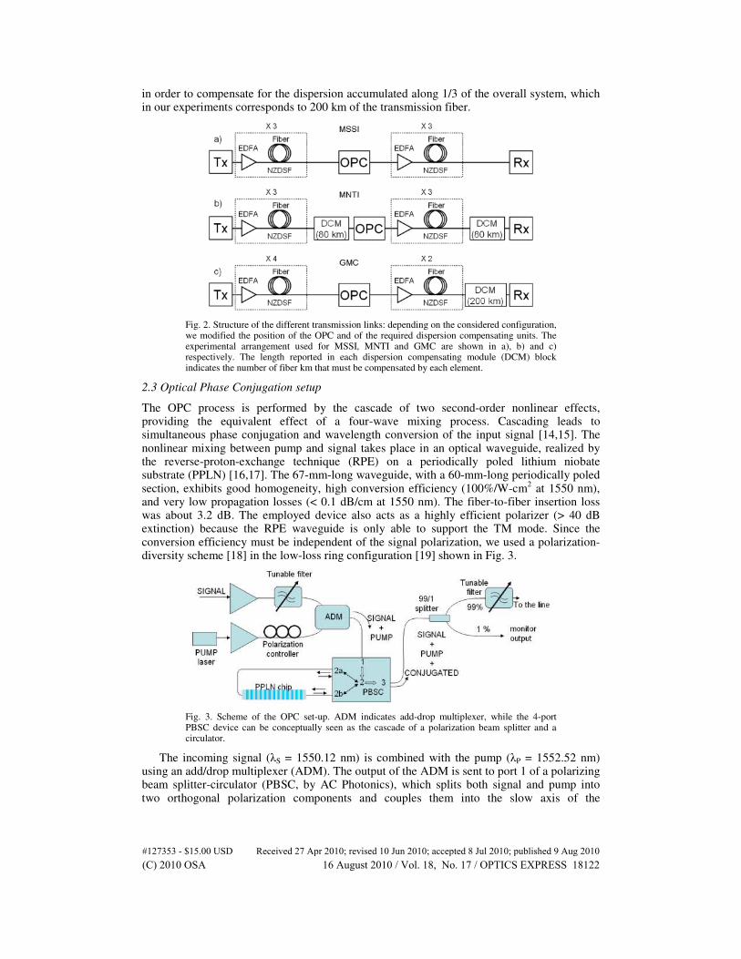
erbium-doped fiber amplifiers (EDFAs), with their output power set to 12 dBm (≈16 mW). In order to set up the different configurations, an optical phase conjugator and the required dispersion compensating modules (DCM) have been properly inserted along the transmission link. The structures of the three different links realized to test the MSSI, MNTI, and GMC approach are illustrated in Fig. 2 (a, b and c, respectively). The MSSI configuration is realized by simply inserting the OPC at the end of the third span, such that no dispersion compensation unit is required at the receiver. The MNTI link also locates the OPC device at around mid-span, but uses a slightly different apparatus as described in Section 2.3. A small dispersion-compensating element is introduced at the receiver in order to compensate for the residual chromatic dispersion. Finally, the GMC system is realized by positioning the OPC after the fourth fiber span. In this case, as the OPC device divides the link in two strongly asymmetrical sections, a large dispersion-compensating stage is required before the receiver
#127353 - $15.00 USD Received 27 Apr 2010; revised 10 Jun 2010; accepted 8 Jul 2010; published 9 Aug 2010(C) 2010 OSA 16 August 2010 / Vol. 18, No. 17 / OPTICS EXPRESS 18121
in order to compensate for the dispersion accumulated along 1/3 of the overall system, which in our experiments corresponds to 200 km of the transmission fiber.
Fig. 2. Structure of the different transmission links: depending on the considered configuration, we modified the position of the OPC and of the required dispersion compensating units. The experimental arrangement used for MSSI, MNTI and GMC are shown in a), b) and c) respectively. The length reported in each dispersion compensating module (DCM) block indicates the number of fiber km that must be compensated by each element.
2.3 Optical Phase Conjugation setup
The OPC process is performed by the cascade of two second-order nonlinear effects, providing the equivalent effect of a four-wave mixing process. Cascading leads to simultaneous phase conjugation and wavelength conversion of the input signal [14,15]. The nonlinear mixing between pump and signal takes place in an optical waveguide, realized by the reverse-proton-exchange technique (RPE) on a periodically poled lithium niobate substrate (PPLN) [16,17]. The 67-mm-long waveguide, with a 60-mm-long periodically poled section, exhibits good homogeneity, high conversion efficiency (100%/W-cm
2 at 1550 nm),
and very low propagation losses (< 0.1 dB/cm at 1550 nm). The fiber-to-fiber insertion loss was about 3.2 dB. The employed device also acts as a highly efficient polarizer (> 40 dB extinction) because the RPE waveguide is only able to support the TM mode. Since the conversion efficiency must be independent of the signal polarization, we used a polarization-diversity scheme [18] in the low-loss ring configuration [19] shown in Fig. 3.
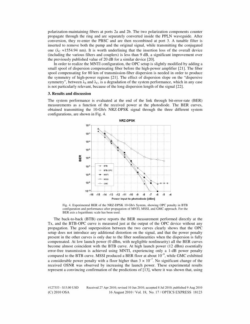
Fig. 3. Scheme of the OPC set-up. ADM indicates add-drop multiplexer, while the 4-port PBSC device can be conceptually seen as the cascade of a polarization beam splitter and a circulator.
The incoming signal (λS = 1550.12 nm) is combined with the pump (λP = 1552.52 nm) using an add/drop multiplexer (ADM). The output of the ADM is sent to port 1 of a polarizing beam splitter-circulator (PBSC, by AC Photonics), which splits both signal and pump into two orthogonal polarization components and couples them into the slow axis of the
#127353 - $15.00 USD Received 27 Apr 2010; revised 10 Jun 2010; accepted 8 Jul 2010; published 9 Aug 2010(C) 2010 OSA 16 August 2010 / Vol. 18, No. 17 / OPTICS EXPRESS 18122
polarization-maintaining fibers at ports 2a and 2b. The two polarization components counter propagate through the ring and are separately converted inside the PPLN waveguide. After conversion, they re-enter the PBSC and are then recombined at port 3. A tunable filter is inserted to remove both the pump and the original signal, while transmitting the conjugated
one (λC ≈1554.94 nm). It is worth underlining that the insertion loss of the overall device (including the various filters and couplers) is less than 9 dB, a significant improvement over the previously published value of 20 dB for a similar device [20].
In order to realize the MNTI configuration, the OPC setup is slightly modified by adding a small spool of dispersion compensating fiber before the high-power amplifier [21]. The fiber spool compensating for 80 km of transmission-fiber dispersion is needed in order to produce the symmetry of high-power regions [21]. The effect of dispersion slope on the “dispersive symmetry”, between λS and λC, is a degradation of the system performance, which in any case is not particularly relevant, because of the long dispersion length of the signal [22].
3. Results and discussion
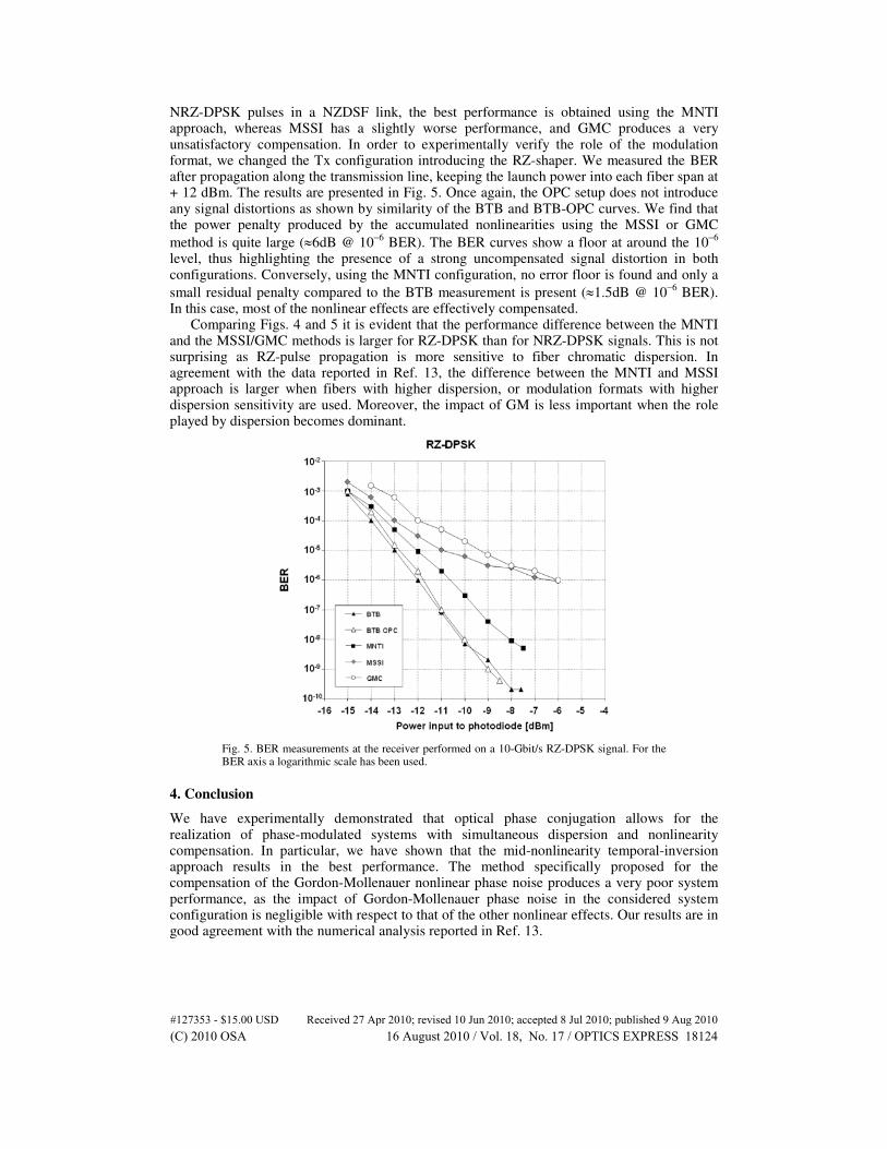
The system performance is evaluated at the end of the link through bit-error-rate (BER) measurements as a function of the received power at the photodiode. The BER curves, obtained transmitting the 10-Gb/s NRZ-DPSK signal through the three different system configurations, are shown in Fig. 4.
Fig. 4. Experimental BER of the NRZ-DPSK 10-Gb/s System, showing OPC penalty in BTB configuration and performance after propagation of MNTI, MSSI, and GMC approach. For the BER axis a logarithmic scale has been used.
The back-to-back (BTB) curve reports the BER measurement performed directly at the Tx, and the BTB-OPC curve is measured just at the output of the OPC device without any propagation. The good superposition between the two curves clearly shows that the OPC setup does not introduce any additional distortion on the signal, and that the power penalty present in the other curves is only due to the fiber nonlinearities when the dispersion is fully compensated. At low launch power (0 dBm, with negligible nonlinearity) all the BER curves become almost coincident with the BTB curve. At high launch power (12 dBm) essentially error-free transmission is achieved using MNTI, experiencing only a 1-dB power penalty
compared to the BTB curve. MSSI produced a BER floor at about 10−9
, while GMC exhibited
a considerable power penalty with a floor higher than 3 × 10⁻⁷
. No significant change of the received OSNR was observed by increasing the launch power. These experimental results represent a convincing confirmation of the predictions of [13], where it was shown that, using
#127353 - $15.00 USD Received 27 Apr 2010; revised 10 Jun 2010; accepted 8 Jul 2010; published 9 Aug 2010(C) 2010 OSA 16 August 2010 / Vol. 18, No. 17 / OPTICS EXPRESS 18123
NRZ-DPSK pulses in a NZDSF link, the best performance is obtained using the MNTI approach, whereas MSSI has a slightly worse performance, and GMC produces a very unsatisfactory compensation. In order to experimentally verify the role of the modulation format, we changed the Tx configuration introducing the RZ-shaper. We measured the BER after propagation along the transmission line, keeping the launch power into each fiber span at + 12 dBm. The results are presented in Fig. 5. Once again, the OPC setup does not introduce any signal distortions as shown by similarity of the BTB and BTB-OPC curves. We find that the power penalty produced by the accumulated nonlinearities using the MSSI or GMC
method is quite large (≈6dB @ 10−6
BER). The BER curves show a floor at around the 10−6
level, thus highlighting the presence of a strong uncompensated signal distortion in both configurations. Conversely, using the MNTI configuration, no error floor is found and only a
small residual penalty compared to the BTB measurement is present (≈1.5dB @ 10−6
BER). In this case, most of the nonlinear effects are effectively compensated.
Comparing Figs. 4 and 5 it is evident that the performance difference between the MNTI and the MSSI/GMC methods is larger for RZ-DPSK than for NRZ-DPSK signals. This is not surprising as RZ-pulse propagation is more sensitive to fiber chromatic dispersion. In agreement with the data reported in Ref. 13, the difference between the MNTI and MSSI approach is larger when fibers with higher dispersion, or modulation formats with higher dispersion sensitivity are used. Moreover, the impact of GM is less important when the role played by dispersion becomes dominant.
Fig. 5. BER measurements at the receiver performed on a 10-Gbit/s RZ-DPSK signal. For the BER axis a logarithmic scale has been used.
4. Conclusion
We have experimentally demonstrated that optical phase conjugation allows for the realization of phase-modulated systems with simultaneous dispersion and nonlinearity compensation. In particular, we have shown that the mid-nonlinearity temporal-inversion approach results in the best performance. The method specifically proposed for the compensation of the Gordon-Mollenauer nonlinear phase noise produces a very poor system performance, as the impact of Gordon-Mollenauer phase noise in the considered system configuration is negligible with respect to that of the other nonlinear effects. Our results are in good agreement with the numerical analysis reported in Ref. 13.
#127353 - $15.00 USD Received 27 Apr 2010; revised 10 Jun 2010; accepted 8 Jul 2010; published 9 Aug 2010(C) 2010 OSA 16 August 2010 / Vol. 18, No. 17 / OPTICS EXPRESS 18124