Optical processing of pulsed Doppler and FM stepped radar signals David Casasent and Francisco Casasayas A real-time radar processor with an electron beam addressed KD 2 PQ 4 light valve as the input electrical- to-optical transducer is described. The input format, output plane pattern, and the required optical pro- cessing of pulsed Doppler and FM stepped radar data on this system are discussed. Experimental output plane patterns with actual radar data are presented. Although these data are processed off-line, the pro- cessing is performed at real-time data rates. I. Introduction The advantages of optical data processing are well known. Optical systems offer high speed and paral- lel processing capabilities possible with powerful op- erations of complex two-dimensional Fourier trans- forms' and correlations 2 with simple and relatively inexpensive lenses. The relationship between the ra- diation pattern from a phased array and the applied electrical signals is the same as the relationship be- tween the patterns in the input and output planes of a lens. This analogy has been applied to the process- ing of phased array antenna data. 3 The basic impediment in the realization of any practical optical processor for radar systems is the input transducer required to convert the received radar signals into coherent optical signals. Film transparencies have been used extensively to prove the feasibility of various input formats and process- ing operations for phased array antennas 45 and pulsed-Doppler and FM stepped radar systems. 6 While offering high resolution, film is neither a real- time nor a reusable input medium. Most input transducers suggested for optically processing radar data have been ultrasonic light modulators that use the Debye-Sears, 3 the Raman-Nath, 7 or the Bragg ef- fect. 7 Reported applications of the modulators have been restricted to the analysis of phased array radar data. The only other previously reported demon- stration of optically processed pulsed-Doppler data 89 used the membrane light modulators as the input transducer. The relative advantages of these various input transducers will be compared in the next section. The authors are with the Carnegie-Mellon University, Depart- ment of Electrical Engineering, Pittsburgh, Pennsylvania 15213. Received 24 July 1974. The real-time electrical-to-optical input transducer used in this work is an electron beam addressed KD 2 PO 4 light valve. The theory of phased array an- tenna processing with this device has been presented previously.' 0 "'1 Real-time optical processing of lin- ear' 2 and planar 3 phased array antenna data with this light valve has been reported recently. This input transducer and the supporting optical system have been interfaced to a PDP-11/15 minicomputer to form a hybrid optical/digital processor. 14 The programmability, automatic analysis, and the digital controlled feedback features that such a hybrid sys- tem offers are particularly advantageous in radar processing. By properly allocating the processing and analysis roles of a given data analysis problem to the optical and digital sections of the processor, an optimum system can result. Toward the goal of implementing several radar processing problems on the same optical processor, we now report on an extension of this light valve sys- tem to the processing of pulsed-Doppler and FM stepped radar data. In these applications, the poten- tially wide bandwidth and processing capability of an optical system can be utilized by recording the re- turned i.f. radar signals directly. These applications also demonstrate the ability of the electrooptical sys- tem in processing real radar data rather than radar data produced by waveform generators, as was the case in the linear and planar phased array electroopt- ical processing.' 2 "1 3 Following a brief discussion and comparison of sev- eral input modulators and a review of conventional pulsed-Doppler processing in which the terms used and the required operations are formulated, an input format suitable for the electron beam addressed light valve transducer is described. The output of the op- tical processor is then shown to be identical to that of the ideal pulsed-Doppler correlator. Examples of ac- 1364 APPLIED OPTICS / Vol. 14, No..6 / June 1975
Transcript
Optical processing of pulsed Doppler and FM steppedradar signals
David Casasent and Francisco Casasayas
A real-time radar processor with an electron beam addressed KD2PQ4 light valve as the input electrical-to-optical transducer is described. The input format, output plane pattern, and the required optical pro-cessing of pulsed Doppler and FM stepped radar data on this system are discussed. Experimental outputplane patterns with actual radar data are presented. Although these data are processed off-line, the pro-cessing is performed at real-time data rates.
I. Introduction
The advantages of optical data processing are wellknown. Optical systems offer high speed and paral-lel processing capabilities possible with powerful op-erations of complex two-dimensional Fourier trans-forms' and correlations2 with simple and relativelyinexpensive lenses. The relationship between the ra-diation pattern from a phased array and the appliedelectrical signals is the same as the relationship be-tween the patterns in the input and output planes ofa lens. This analogy has been applied to the process-ing of phased array antenna data.3
The basic impediment in the realization of anypractical optical processor for radar systems is theinput transducer required to convert the receivedradar signals into coherent optical signals. Filmtransparencies have been used extensively to provethe feasibility of various input formats and process-ing operations for phased array antennas 4 5 andpulsed-Doppler and FM stepped radar systems.6While offering high resolution, film is neither a real-time nor a reusable input medium. Most inputtransducers suggested for optically processing radardata have been ultrasonic light modulators that usethe Debye-Sears,3 the Raman-Nath,7 or the Bragg ef-fect.7 Reported applications of the modulators havebeen restricted to the analysis of phased array radardata. The only other previously reported demon-stration of optically processed pulsed-Doppler data8 9
used the membrane light modulators as the inputtransducer.
The relative advantages of these various inputtransducers will be compared in the next section.
The authors are with the Carnegie-Mellon University, Depart-ment of Electrical Engineering, Pittsburgh, Pennsylvania 15213.
Received 24 July 1974.
The real-time electrical-to-optical input transducerused in this work is an electron beam addressedKD2PO4 light valve. The theory of phased array an-tenna processing with this device has been presentedpreviously.' 0 "'1 Real-time optical processing of lin-ear' 2 and planar 3 phased array antenna data withthis light valve has been reported recently. Thisinput transducer and the supporting optical systemhave been interfaced to a PDP-11/15 minicomputerto form a hybrid optical/digital processor.1 4 Theprogrammability, automatic analysis, and the digitalcontrolled feedback features that such a hybrid sys-tem offers are particularly advantageous in radarprocessing. By properly allocating the processingand analysis roles of a given data analysis problem tothe optical and digital sections of the processor, anoptimum system can result.
Toward the goal of implementing several radarprocessing problems on the same optical processor,we now report on an extension of this light valve sys-tem to the processing of pulsed-Doppler and FMstepped radar data. In these applications, the poten-tially wide bandwidth and processing capability of anoptical system can be utilized by recording the re-turned i.f. radar signals directly. These applicationsalso demonstrate the ability of the electrooptical sys-tem in processing real radar data rather than radardata produced by waveform generators, as was thecase in the linear and planar phased array electroopt-ical processing.' 2"13
Following a brief discussion and comparison of sev-eral input modulators and a review of conventionalpulsed-Doppler processing in which the terms usedand the required operations are formulated, an inputformat suitable for the electron beam addressed lightvalve transducer is described. The output of the op-tical processor is then shown to be identical to that ofthe ideal pulsed-Doppler correlator. Examples of ac-
1364 APPLIED OPTICS / Vol. 14, No..6 / June 1975
(b)
Fig. 1. Real-time electron beam addressed KD2 PO4 light valve input transducer. (a) Schematic code: 1, input and output optical win-dows; 2, write electron gun; 3, KD2 PO4 target crystal; 4, transparent conducting electrode and substrate; 5, erase electron gun. (b) Photo-
graph of device.
tual i.f. pulsed-Doppler radar data optically pro-cessed off-line, but at real-time rates, with theKD2PO4 light valve are then presented. Extensionsof this processing technique to the case of a linearFM-stepped radar system, as well as output planepatterns for actual linear FM-stepped radar data op-tically processed in real time, are also included.
11. Input Transducer
A schematic of the input transducer used is shownin Fig. 1(a), and a photograph of the device is shownin Fig. 1(b). The device consists of two off-axis elec-tron guns [2 and 5 in Fig. 1(a)] and a transparentelectrooptic target crystal (3 in Fig. 1(a)) of potassi-um dideuterium phosphate (KD2PO4) in a vacuumenclosure. The input electrical signals are applied tothe cathode of the write gun [2 in Fig. 1(a)] in syn-chronization with a raster scan deflection of the elec-tron beam. The charge pattern deposited on the tar-get crystal by the write gun produces a voltage distri-bution across the crystal surface as a controllablefunction of position. By the linear, longitudinal,electrooptic or Pockels effect,23 this voltage distribu-tion can spatially modulate an incident collimatedlaser beam point by point. The light valve used inthis radar processor is operated in the transmissionmode with the electron guns off-axis and the laserbeam passing directly through the crystal. A discus-sion of the off-axis electrooptic correction circuitry isfound in Ref. 21. For high resolution, the targetcrystal is operated at its transition temperature2 0 bythermoelectric Peltier cells. Since transition tem-perature operation produces long storage times, on-line operation is maintained by erasure of the chargedistribution on the crystal surface by the erase elec-tron gun (5 in Fig. 1(a)). This electron gun operatesat a low accelerating potential, and erasure isachieved by secondary emission from the surface of
the crystal.15 Nearly 1000 X 1000 point resolutionand operation at 30 frames/sec are possible with thisdevice. References 15-20 contain detailed descrip-tions of this light valve and its various applicationsand operating modes.
While the KD2PO4 light valve does not possess theresolution of film or acoustooptic devices, it is a real-time reusable medium with a storage mode. Acous-tooptic modulators, besides requiring considerablymore input source power and exhibiting a lower mod-ulation index and contrast ratio than the KD2PO4light valve, lack a storage feature; the output patternis available only during the relatively short time thereturned signals fill the delay medium. Further-more, these acoustooptic devices are inherently onedimensional, and multiple cells must be fabricated toprocess parallel channels adequately. The mem-brane light modulator is also line-addressed, and fur-thermore, since it is a pure phase modulator, an apriori knowledge of the rf phase of the returnedradar data is necessary before the data can be pro-cessed.
Ill. Pulsed Doppler Radar Processing
A. Radar System
In the pulsed Doppler radar system required foroptically processed Doppler data, the transmittedfrequency fo is derived from the sum of the STALOand COHO reference oscillator frequencies f, and f,Prior to transmission, this rf signal is modulated by ahigh power pulse amplifier with pulsewidth Tp at apulse repetition frequency = fr = 1/Tr. To processthe returned signals electrooptically, they are firstmixed with the STALO; the resulting i.f. signal isthen amplified, range-gated, and fed to the electronicsupport system for the KD2PO4 light valve. Thisdiffers from the classical Doppler radar processorthat performs Doppler frequency discrimination by a
June 1975 / Vol. 14, No. 6 / APPLIED OPTICS 1365
band of contiguous narrow-band filters. Barton22
has described the pulsed Doppler processing re-quired.
For the nth repetition interval, the received signalfrom a point target at a range R and velocity vr is
enr(t) = Er cos[21Tfo(t - t) + qct(t - t)] (1)
where the range delay t = 2R/c = 2(Ri + vrt)/c = ti+ 2vrt/c, and Ri is the target's range at some time ori-gin t = 0. The phase kt(t) = s(t) + kc(t) + ko(t) isthe transmitter phase relative to its reference wave ata frequency ft; 08 (t), /,(t), and Loft) are the phase ofthe STALO, COHO, and transmitted wave, respec-tively. After we heterodyne and select the differencefrequency, the received i.f. signal from the nth repeti-tion interval, ignoring the second-order Dopplershift, is
where d = 2Vrfo/C is the Doppler frequency shift.With the STALO, COHQ, and transmitter stable,and the product fTr chosen to be an integer, the onlydifference between eni(t) and ei+ (t) is the phaseterm
P = -27%dTry
and the difference for N consecutive returns isAN = -(N- )47af1f,,
1 N_1M(t) = ha g, (t - nfTr),
n.O(6)
and
= ) P (t) -{j 1 for I t To/2,A, M= PPM= ~ 0 otherwise, (7)
and the total signal energy has been normalized.The received signal is
R(t) = Ig(t - To) expCj27(fo - IR)(t - -rR)] (8)
where R is the range delay and R is the Dopplershift. The correlation of ,R(t) with a signal Als(t)identical to A~(t), but with a time delay s and Dop-pler frequency vs, is
(9)
or4(T) = X(7, v) expj27T(fo -Us) T] (10)
where r =- - rs + TR, V = R - s, and x(r,v) isthe ambiguity function of the transmitted signal en-velope
X(7, M = /t(t) y*(t - T) expj27Tvt)dt (11)(3)
(4)
from which a linear phase slope proportional to thetarget's velocity is seen to exist across the returnedi.f. signals. This point is crucial in the implementa-tion of an optical processor for a pulsed Dopplerradar system.
Existing radar receivers extract this velocity infor-mation by performing a correlation in which the vec-tors of the returned pulses are rotated by the phaseof an assumed linear phase slope and a vector addi-tion is performed on all the pulses. This process isrepeated for every velocity bin to be investigatedwithin the same range bin. The output of the corre-lator is the cross section across the Doppler axis ofthe ambiguity waveform of the transmitted pulsetrain. The displacement of the main peak of thisambiguity function yields the desired Doppler shift.
with a maximum at r = 0, = 0, or vs = R, = R-TrS.
By substituting into Eq. (11), one obtains
1 .)siniv(N - fTrp((N1) (r PTr, ) sinivT l
x expurv(N - 1 + p)Tr], (12)
where Xc is the ambiguity function of the componentsignal. If we neglect the phase factor, the ambiguityfunction (r,v) is the summation of the series of so-called p surfaces. These p surfaces are repeated atintervals of Tr along the delay axis and are sampledat intervals of /Tr in the Doppler domain with theiramplitudes decreasing linearly with p. For a rectan-gular envelope, Xc(O,v)l = Tp sinc(vTp). The widthof the grating lobes along v increases with p, with thesmallest grating lobe width being 2/NTr for p = 0.The fine structure of the ambiguity function x(O,v)along the Doppler axis with an arbitrary origin at =0 for the p = 0 surface of interest is given by
To verify that the optical processor to be usedsatisfies the requirements of the ideal pulsed Dopplercorrelator, the conventional correlation analysis isconsidered first. The analytic signal approach isused to simplify notation. The transmitted wave-form is
$(t) = (t) exp(j2irf 0t), (5)
where the signal envelope is
and represents the output of a filter matched to aDoppler shift vo. For a returned signal with a Dop-pler frequency Pi, the output of the filter is given bythe value of IX(0,v)12, where v = vo - v and has apeak at v = 0, or for vo = , as expected.
The ideal Doppler correlator should have an out-put proportional to fX(0,V)12 for all possible values ofvo and v. The output ep(v,) of the ideal processorfor a returned signal with a Doppler shift vl consistsof I X (0, - V')12 sampled by grating lobes spaced atdistances v + i/T, where i = 0, 1,... or
1366 APPLIED OPTICS / Vol. 14, No. 6 / June 1975
n = E., OR (t) Os* (t - �) dt,
vPIv)
3 2 1 0 1 2 3
Tr Tr Tr Tr Tr Tr
Fig. 2. Output of ideal pulsed Doppler radar processor along theDoppler axis.
ev() = _X VI)1LN sin7rTr(v Z)1 (14)
as shown in Fig. 2. The location of the peak alongthe v axis is a measure of the target's Doppler fre-quency. The measurement is performed with thezero-order lobe of I xc(0,v)I whose position can be de-termined unambiguously over the interval -1/2Tr •v • 1/2 Tr, corresponding to an unambiguous velocityinterval (bin),
Av,. = CAV/2fo = A0 /2T. (15)
Outside of this interval, the grating lobes of(sinirvNTr)/(sinrvTr) yield the ambiguities in Dop-pler v, + Tr (where i = 0, 1, ... ) introduced by thesignal repetition itself. The improvement in Dop-pler resolution achieved by pulse repetition can befully utilized only if the target's Doppler spread doesnot exceed 1/Tr, in otherwise foldover will occur. Nvalues of Doppler shift are resolvable in the unam-biguous area.
Vi
C. Optical ProcessorThe implementation of the optical processor re-
quired to produce similar results will now be consid-ered. Specifically, the input format, required pro-cessing, and output plane pattern will be discussed.The nth i.f. signal returned from the same target hasthe form
where t = 2nvrTr/c = differential time delay per ele-ment and Otn = 2nvrTr/Xc = number of cycles of rfphase shift = na.
The approximation in Eq. (16) assumes tn max <<Tp and fd << fif. Equation (16) describes the voltagedistribution written on the nth line of the target crys-tal by the electron gun. Since the electron gun scansin a raster format and the received signals are se-quential in nature, no delay lines are required as inthe optical processing of linear phased arrays,10-' 3
and the received electrical signals in the form of Eq.(16) can be fed to the input modulator's video ampli-fier and written directly on the crystal. The horizon-tal raster scan time (Th = 63.5 ,usec in the TV scanformat used) places an upper bound on the system'spulse repetition frequency this scan rate can, ofcourse, be altered to accommodate a variety of sys-tems. It was retained for convenience in this presenteffort. With Th a fraction of the radar's pulse repeti-tion period, the integration period Ti for a givenrange bin will be much less than the pulse repetitionperiod Tr.
Since only negative signal polarities can be formedon the crystal by the electron beam, the most faithfuloptical transmission function for the light valve canbe written as
NT(x,y) = E 6(y - nl)[1 + yin(xTj1D)]Px(x), (17)
V
,v~~~~~~~~~~~~~~~~~~~
______~~~~~~~~~~~~~~~~~~~~~~~~~~~I
."v
Fig. 3. Output plane pattern for pulsed Doppler radaroptical processor.
U1 U
2 T
U -I A
June 1975 / Vol. 14, No. 6 / APPLIED OPTICS 1367
I %.IIII1
Q:>__ - ____
IFIu . 12
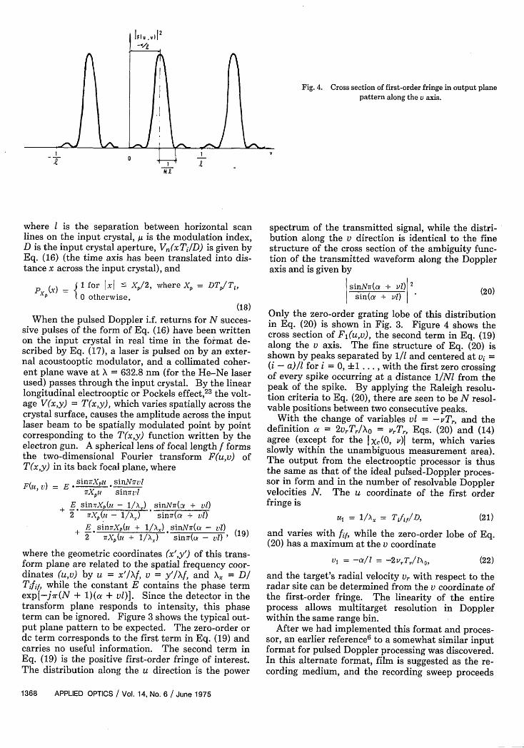
Fig. 4. Cross section of first-order fringe in output planepattern along the v axis.
0
where is the separation between horizontal scanlines on the input crystal, g is the modulation index,D is the input crystal aperture, Vj(xT 1/D) is given byEq. (16) (the time axis has been translated into dis-tance x across the input crystal), and
pCy) = 1 for xj ' Xp/2, where X = DT/Tj,PXP 0 otherwise.
(18)
When the pulsed Doppler i.f. returns for N succes-sive pulses of the form of Eq. (16) have been writtenon the input crystal in real time in the format de-scribed by Eq. (17), a laser is pulsed on by an exter-nal acoustooptic modulator, and a collimated coher-ent plane wave at X = 632.8 nm (for the He-Ne laserused) passes through the input crystal. By the linearlongitudinal electrooptic or Pockels effect,23 the volt-age V(x,y) = T(x,y), which varies spatially across thecrystal surface, causes the amplitude across the inputlaser beam to be spatially modulated point by pointcorresponding to the T(x,y) function written by theelectron gun. A spherical lens of focal length f formsthe two-dimensional Fourier transform F(u,v) ofT(x,y) in its back focal plane, where
where the geometric coordinates (x',y') of this trans-form plane are related to the spatial frequency coor-dinates (u,v) by u = x'/Xf, v = y'/Xf, and X = DITifif, while the constant E contains the phase termexp[-j-r(N + 1)(a + v)]. Since the detector in thetransform plane responds to intensity, this phaseterm can be ignored. Figure 3 shows the typical out-put plane pattern to be expected. The zero-order ordc term corresponds to the first term in Eq. (19) andcarries no useful information. The second term inEq. (19) is the positive first-order fringe of interest.The distribution along the u direction is the power
spectrum of the transmitted signal, while the distri-bution along the v direction is identical to the finestructure of the cross section of the ambiguity func-tion of the transmitted waveform along the Doppleraxis and is given by
sinNr(a + vi) 2sin( + vi) (20)
Only the zero-order grating lobe of this distributionin Eq. (20) is shown in Fig. 3. Figure 4 shows thecross section of Fj(u,v), the second term in Eq. (19)along the v axis. The fine structure of Eq. (20) isshown by peaks separated by 1/1 and centered at vi =(i - a)/i for i = 0, +1 .. ., with the first zero crossingof every spike occurring at a distance /NI from thepeak of the spike. By applying the Raleigh resolu-tion criteria to Eq. (20), there are seen to be N resol-vable positions between two consecutive peaks.
With the change of variables v = -Tr, and thedefinition a = 2rTr/X = vrTr, Eqs. (20) and (14)agree (except for the Xc(O, v)l term, which variesslowly within the unambiguous measurement area).The output from the electrooptic processor is thusthe same as that of the ideal pulsed-Doppler proces-sor in form and in the number of resolvable Dopplervelocities N. The u coordinate of the first orderfringe is
u = /A = Tf/D, (21)
and varies with fif, while the zero-order lobe of Eq.(20) has a maximum at the v coordinate
V = -/ = -2vrTr/1N,, (22)
and the target's radial velocity vr with respect to theradar site can be determined from the v coordinate ofthe first-order fringe. The linearity of the entireprocess allows multitarget resolution in Dopplerwithin the same range bin.
After we had implemented this format and proces-sor, an earlier references to a somewhat similar inputformat for pulsed Doppler processing was discovered.In this alternate format, film is suggested as the re-cording medium, and the recording sweep proceeds
1368 APPLIED OPTICS / Vol. 14, No. 6 / June 1975
I
It
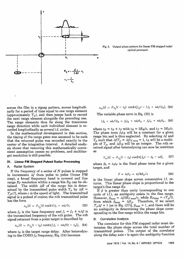
Fig. 5. Output plane pattern for linear FM stepped radaroptical processor.
VI U
F. = 2 AW
us 1
I x
across the film in a zigzag pattern, moves longitudi-nally for a period of time equal to one range element(approximately Tp), and then jumps back to recordthe next range element alongside the preceding one.The range elements thus lie along the transverserange direction while each individual element is re-corded longitudinally as several i.f. cycles.
In the mathematical development in this section,the timing of the range gates was assumed to be suchthat the returned pulse was recorded exactly in thecenter of the integration interval. A detailed analy-sis shows that removing this mathematically conve-nient assumption causes no problems, and multitar-get resolution is still possible.
IV. Linear FM Stepped Pulsed Radar Processing
A. Radar System
If the frequency of a series of N pulses is steppedin increments Af from pulse to pulse (linear FMstep), a broad frequency band is covered and finerange RF resolution within a range bin RB can be ob-tained. The width AR of the range bin is deter-mined by the transmitted pulse width Tp by AR Tpc/2, where c is the speed of light. The transmittedsignal is a pulsed rf cosine; the nth transmitted pulsehas the form
et(t) = P(t) cos27r(fo + n Af)t, (23)
where fo is the base frequency and ft = fo + nAf isthe transmitted frequency of the nth pulse. The nthsignal returned from a point target is described by
where tR = tB + tF with tB = 2RB/C, and tF = 2RF/c.The phase term fotB will be a constant for a givenrange bin and is thus neglected. By selecting Af andTp such that AfTp = AftF max = 1, tB will be a multi-ple of Tp, and A/tB will be an integer. The nth re-ceived signal after heterodyning can now be rewrittenas
Vn,(t) = PT (t - tR) cos27T.f4ft - g - no3], (27)
where fo = ttF is the fixed phase term for a giventarget, and
3 = AftF = Af2RF/c (28)
is the linear phase slope across consecutive i.f. re-turns. This linear phase slope is proportional to thetarget's fine range RF.
If / is greater than unity (corresponding to onecycle of i.f.), an ambiguity exists in the fine range.However, /3max = AJ2RF max/C, while RFmax = cTp/2,from which O3max = Aftp. Therefore, if we selectTpAf = 1 [as in Eq. (27)], 0max = 1, and there will beno ambiguity in determining the phase slope corre-sponding to the fine range within the range bin.
B. Correlation Analysis
The correlator for this FM stepped radar must de-termine the phase slope across the total number oftransmitted pulses. The output of the correlatoralong the delay axis X is again the ambiguity function
June 1975 / Vol. 14, No. 6 / APPLIED OPTICS 1369
VI iz=>i
i
IIIII
I %.IIII
I
(=)I-- - ____
Table I. Pulsed Doppler Radar System Parameters
N = 100 1 = 0.19 mmT = 20psec D = 5 cmfo = 5.650 GHz T = 52.5 psecfif = 1 MHz
of the transmitted pulse train as in the pulsed Dop-pler correlator. The mathematical development ofthe ambiguity function closely follows the treatmentin Sec. III with exp(j2irrnAf) substituted forexp(j27rvnTr). The final form of the ambiguityfunction for the p = 0 surface is
X(v v) = +xc(T, v)Z exp(27rTnAf). (29)n=O
The fine structure of the envelope of x(r,v) along thev = 0 axis is
s(T, 0) = I Z exp(j27rTrnf) = sinlrf (30)n=1 sin7rrTaf
which is analogous to the pulsed Doppler case. Byanalogy with Sec. III, the output of this ideal proces-sor has N resolvable fine range positions betweenconsecutive ambiguities where the ambiguities areseparated by ri = 1/Af.
C. Optical Processor
The input format used in the pulsed Doppler caseapplies here also, with substituted for a where isthe number of cycles of phase shift per pulse. At ul= /X the displacement of the zero-order lobeacross the v axis is
l = -,6/i = -2RFAf/lc. (31)
The target's fine range can thus be found from the v1measurement:
RF = -(c/2Af)v 1. (32)
The typical output plane pattern to be expected isshown in Fig. 5.
V. Experimental Results
A. Pulsed Doppler Radar Processing
Real pulsed Doppler radar data were fed to thevideo amplifier of the KD2PO4 input transducer andwritten in real time on the target crystal in the for-mat described by Eq. (17). The radar system andinput plane parameters are listed in Table I. Thetwo-dimensional Fourier transform of this input lightdistribution was formed by a 0.495-m focal lengthspherical lens, and an objective and eyepiece wereused to project the transform plane patterns to a rea-sonable size.
Figure 6 shows the magnified output plane patternfor an aircraft target from a pulsed Doppler radarsystem with a pulse repetition frequency of 2.5 kHz.The horizontal spatial frequency coordinate of thefirst-order fringe is u = fifTi/D = 1050 m-1 . Withan effective focal length f = 44 m for the magnifiedFourier transform system, the theoretical horizontal
geometric displacement of the first-order fringe is xl'= uXf = 29 mm, which is identical to the measuredvalue. The measured value y1' of the vertical geo-metric displacement of the first-order fringe is 37.5mm, which corresponds to a spatial frequency v =1328 m-l and a fine radial target velocity of -17 m/sec. The unambiguous Doppler frequency intervalof 1/Tr = 2.5 kHz corresponds to an unambiguous ve-locity interval (C/2fo)(1/Tr) = 62 m/sec.
Figure 7 shows the magnified output Fourier planepattern for the case of two aircraft in the same rangebin. The returns for N = 100 pulses from the samereal pulsed Doppler radar system were again used.The pulse repetition frequency was now 1.25 kHz,corresponding to a 31 m/sec unambiguous velocity in-terval. With an effective magnified Fourier trans-form system focal length f = 33 m, the horizontal'
Fig. 6. Real-time output plane pattern from actual pulsed Dop-pler radar data for a single aircraft target and a pulse repetition
frequency of 2.5 kHz.
Fig. 7. Real-time output plane pattern from actual pulsed Dop-pler radar data for two aircraft in the same range bin and a pulse
repetition frequency of 1.25 kHz.
1370 APPLIED OPTICS / Vol. 14, No. 6 / June 1975
Fig. 8. Real-time output plane pattern due to receiver noise witha pulse repetition frequency of 1.25 kHz.
line by a 0.495-m focal length spherical lens. Theradar system parameters and input plane parametersare listed in Table II.
The magnified optical output plane pattern for astatic target, specifically two towers, is shown in Fig.9. From Table II, the vertical spatial frequencycoordinate of the first-order fringe peak is u1 = fifTJD = 2100 m-. A 2.5X objective and 15X eyepiecewith the 0.495-m focal length transform lens pro-duced a magnified transform lens system with an ef-fective focal length of 17 m. The theoretical verticaldisplacement of the first-order fringe in the system isx1' = u1Xf = 22.5 mm. The y1' value measured fromFig. 9 is 24 mm, corresponding to a spatial frequencyof 2340 m1 and, from Eq. (32), a fine target range of128 m.
The magnified output plane for an aircraft targetis shown in Fig. 10. The measured yi' value of 36.5mm corresponds to a spatial frequency of 3500 m-1and a target fine range of 20 m within the range binused. The unambiguous fine range interval for thisFM stepped radar system was 300 m.
VI. Summary
A brief review of pulsed Doppler and FM steppedradar systems has been given. The required inputformat by which fine velocity and fine range informa-tion about a target can be obtained by optically pro-cessing these returned signals was presented. Theoutput of the optical processor was shown to be iden-tical to the output of an ideal correlator in both radarsystems. An electron-beam-addressed KD2PO4 light
Table II. Linear FM Stepped Radar System Parameters
N = 100 1 = 0. 19 mmT = 0.2 Asec Af = 5 MHz
fo = 5.650 GHz D = 5 cm-ffif= 2 MHz Ti = 52.5 jusec
Fig. 9. Real-time output plane pattern from actual linear FM
, stepped radar data for a static target, a pair of towers.
geometric displacement of the first-order fringe is x1'= u1Xf = 22 mm, which is again identical to the mea-sured value. The measured values y1' and Y2' of thevertical geometric displacements for the two aircraftare 19.5 mm and 41.5 mm, which correspond to spa-tial frequencies v, = 930 m-1 and v2 = 1980 m- 1 andfine radial target velocities of -5.8 m/sec and 12.5m/sec.
Figure 8 is the magnified transform plane patterndue to receiver noise alone, obtained with a pulserepetition frequency of 1.25 kHz, and is useful forreference purposes.
B. Linear FM Stepped Radar Processing
Real linear FM stepped radar data were also pro-cessed in real time by writing the returned i.f. signalson the KD2PO4 target crystal in the specified format.This input pattern was then Fourier-transformed on-
Fig. 10. Real-time output plane pattern from actual linear FMstepped radar data for an aircraft target.
June 1975 / Vol. 14, No. 6 / APPLIED OPTICS 1371
valve was used as the input transducer in the opticalsystem to allow real pulsed Doppler and FM steppedradar data to be processed in real time. The outputof the optical processor agrees with the format pre-dicted by theory and with the numerical values ob-tained from a conventional digital radar processor.
When compared with other optical processors, theelectron-beam-addressed KD2PO4 light valve systemhas the advantage that it does not require a prioriknowledge of the rf phase of all returned signals. Inaddition, it requires less input source power and hasa higher contrast and modulation index than otherreal-time spatial-light modulators for radars, and of-fers a storage feature that facilitates processing.
Current research efforts are concentrating on theuse of other waveform envelopes and correlationtechniques in the Fourier transform plane to increasethe output signal-to-noise ratio and the system'scomputing power.
The continuing support of the Office of Naval Re-search on contract NR048-600 and valuable discus-sions with James Queen of the Applied Physics Labo-ratory of Johns Hopkins University are gratefully ac-knowledged.References1. J. W. Goodman, Introduction to Fourier Optics (McGraw-
Hill, New York, 1968).2. G. W. Stroke, An Introduction to Coherent Optics and Holog-
raphy (Academic, New York, 1969).3. L. Lambert, M. Arm, and A. Aimette, in Optical and Electro-
optical Information Processing, J. T. Tippet et al., Eds. (MITPress, Cambridge, Mass., 1965), Chap. 38.
4. D. C. Beste and E. N. Leith, IEEE Trans. Aero. Electron. Syst.AES-2, 376 (1966).
5. R. E. Williams and K. Von Bieren, Appl. Opt. 10, 1386 (1971).6. W. G. Hoefer, IRE Trans. Mil. Electron. MIL-6, 174 (1962).7. W. T. Maloney, IEEE Spectrum 6, 40 (1969).8. K. Preston, Jr., Coherent Optical Computers (McGraw Hill,
New York, 1972).9. R. A. Meyer, D. G. Grant, and J. L. Queen, Technical Memo-
randum TG1193, Applied Physics Laboratory, The JohnsHopkins University, Sept. 1972.
10. D. Casasent and J. Stephenson, Appl. Opt. 11, 1269 (1972).11. D. Casasent, Soc. for Info. Display Digest, p. 114 (1972).12. D. Casasent and F. Casasayas (submitted to IEEE Trans.
Aero. Electron. Syst.).13. D. Casasent and F. Casasayas (submitted to IEEE Trans.
Aero. Electron. Syst.).14. D. Casasent, IEEE Trans. Comput. C-22, 852 (1973).15. G. Marie, Philips Res. Rept. 22, 119 (1967).16. W. J. Poppelbaum, in Pictorial Pattern Recognition, G. C.
Cheng et al., Eds. (Thompson Book Co., Washington, D.C.,1968).
17. G. G. Goetz, Appl. Phys. Lett. 17, 63 (1970).18. C. J. Salvo, IEEE Trans. Electron. Dev. ED-18, 748 (1971).19. D. Casasent and W. Keicher, in Proceedings, Electro-optical
Systems Design Conference (1972), p. 99.20. D. Casasent, IEEE Trans. Electron. Dev. ED-20, 1109 (1973).21. D. Casasent and F. Caimi, J. Vac. Sci. Technol. 10, 1102
(1973).22. D. Barton, Radar System Analysis (Prentice Hall, Englewood
Cliffs, N. J., 1964).23. B. H. Billings, J. Opt. Soc. Am. 39, 797 (1949).
LASER MATERIALS PROCESSING
A Special Summer Program at MITAugust 4-8, 1975
The program will cover the status of industrial lasersand the application of these lasers in the manufacturingindustry. The full spectrum of industrial laser materialprocessing applications will be treated. Emphasiswill be placed on new developments in metal processingapplications of deep penetration cutting, welding andsurface hardening. The program is geared primarilyfor engineers and designers involved in the manufacturingand product development industry.
For further information on the above programwrite to:
Director of the Summer SessionRoom E19-356Massachusetts Institute of TechnologyCambridge, MA 02139