45
1 Optical Surface-Mount Packaging and Guided-Mode Coupling Shogo Ura Kyoto Institute of Technology, Japan December 4, 2015 The University of Texas at Arlington, Texas
1�
Optical Surface-Mount Packaging and Guided-Mode Coupling
Shogo Ura Kyoto Institute of Technology, Japan
December 4, 2015 The University of Texas at Arlington, Texas

2�
Outline
1. Introduction High-density optical interconnects
2. Typical I/O couplers 45˚ mirrors, grating couplers
Application potential for WDM system
3. High-density vertical coupler Grating coupler with cavity-resonator integration
4. Trials for functional coupler for advanced packaging Guided-mode resonance for stable VCSEL coupling
5. Summary

3�
Paradigm shift for future LSI
Size shrinking Increase of Tr
Paradigm shift
Super global wiring High density massive signal transmission > 20 Tbps
LSI
LSI
LSI
Increase of power dissipation
Future SiP
Small feature size
Jumping production cost
Optimized packaging of multiple LSIs
On-board optical interconnection

4�
Appl. Roadmap on Optical Interconnects
A. F. Benner et al. @IBM, IBM J. Res. & Dev. 49, 755 (2005)

5�
High-density optical interconnect module
High density optical wiring: 20 Tbps in 10mm width
VCSEL array PD array
I/O couplers I/O couplers
Electrical signals Electrical signals
A key issue: how to couple optical signals to optical waveguides

6�
Outline
1. Introduction High-density optical interconnects
2. Typical I/O couplers 45˚ mirrors, grating couplers
Application potential for WDM system
3. High-density vertical coupler Grating coupler with cavity-resonator integration
4. Trials for functional coupler for advanced packaging Guided-mode resonance for stable VCSEL coupling
5. Summary

7�
Embedded 45˚ mirrors
VCSEL
Guiding core
PCB 45-degree mirror
VCSEL
Guiding core
PCB 45-degree mirror
Basic configuration
Coupling with lens
Vertical coupling Easy design
Larger alignment tolerance
NA matching Higher efficiency
NA mismatching
Lens integration Cost Size
Pros
Cons
Pros
Cons
8�
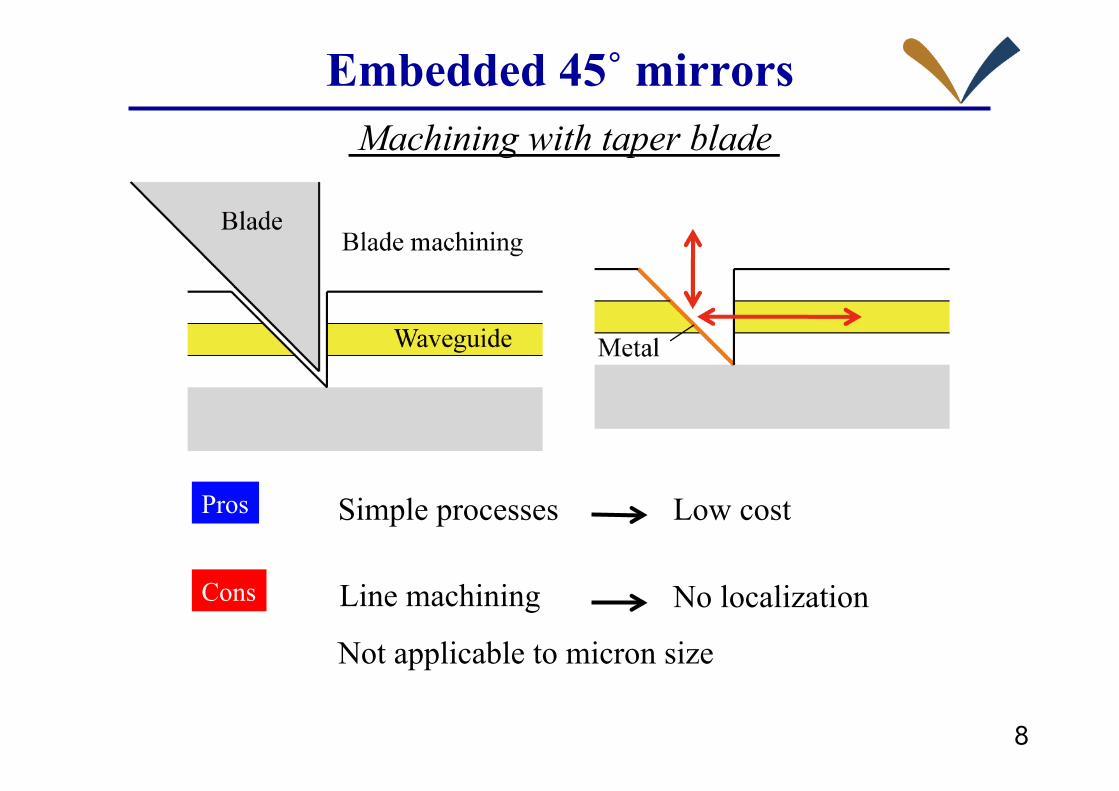
Embedded 45˚ mirrors Machining with taper blade
Low cost
Not applicable to micron size
Line machining No localization
Simple processes Pros
Cons

9�
Embedded 45˚ mirrors
Pros
Cons
Lithography Localization High throughput Low cost
Liquid emersion exposure
Applicable to micron size
Special setup
Tilt exposure

10�
Fabrication of embedded micromirror
Liquid immersion exposure is necessary for realizing an exposure angle of 45˚ in resist.

11�
Coupling by embedded micromirror
Input coupling efficiency : 75%
Output coupling efficiency : 60% J. Inoue et al. @ Kyoto Inst. Tech., J. Lightwave Tech. 30, 1563 (2012)

12�
Grating couplers (GCs)
θa Λ
θs
Grating coupler
Guiding core
Substrate
Air radiation
Substrate radiation
Guided wave
Grating vector
: Wave-vector size in the air
: Wave-vector size in the substrate
: Propagation vector of the guided mode
Air radiation by 1st order diffraction
Substrate radiation by 1st order diffraction
€
K =2πΛ€
β = Nk€
k =2πλ
13�
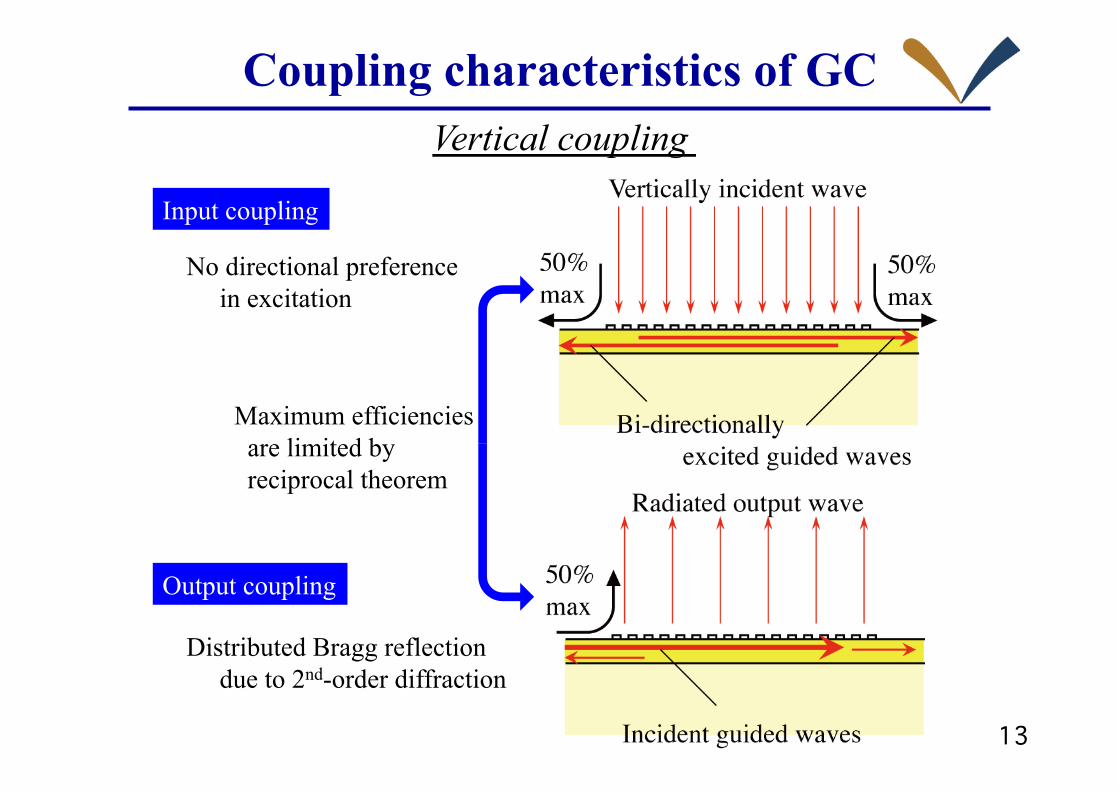
Coupling characteristics of GC Vertical coupling
Maximum efficiencies are limited by reciprocal theorem
Input coupling
No directional preference in excitation
Output coupling
Distributed Bragg reflection due to 2nd-order diffraction

14�
Coupling characteristics of GC Substrate radiation suppression
Optimization of buffer layer thickness
Efficiency enhancement by interference effect

15�
Free-space-wave OADM coupler
TE0: Transmission mode TE1: I/O coupling mode
FGC: Vertical coupling FS wave TE1
DBR: Wavelength selective TE0 TE1

16�
Free-space-wave OADM coupler Preliminary experimental results of 8-ch WDM optical interconnects consisting of 16 FGC/DBR pairs
K. Kintaka et al. @ AIST, IEEE Lightwave Technol. 20, 1398 (2010)
17�
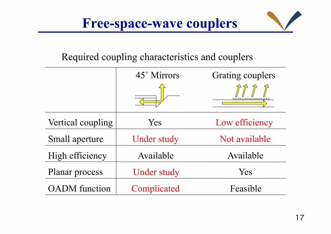
Free-space-wave couplers
Required coupling characteristics and couplers
Vertical coupling
High efficiency
Planar process
Grating couplers 45˚ Mirrors
Small aperture
Yes
Under study
Low efficiency
Not available
OADM function
Available
Complicated Feasible
Available
Yes Under study
18�
Outline
1. Introduction High-density optical interconnects
2. Typical I/O couplers 45˚ mirrors, grating couplers
Application potential for WDM system
3. High-density vertical coupler Grating coupler with cavity-resonator integration
4. Trials for functional coupler for advanced packaging Guided-mode resonance for stable VCSEL coupling
5. Summary

19�
Cavity-resonator-integrated GIC
High-efficiency vertical coupling with small aperture can be realized even if grating coupler itself has low coupling coefficient
Cavity-resonator-integrated grating in/out coupler (CRIGIC)

20�
Design example of CRIGIC
Coupling wavelength 842 nm
TE0 mode index 1.489
Reflectivity 98.8%

21�
Fabrication & characterization CRIGIC of 20µm aperture
Theoretical Experimental
GC w/o cavity resonator needs 500µm aperture to give 60% efficiency.
K. Kintaka et al. @ AIST, Opt. Lett. 35, 1989 (2010)

22�
Free-space-wave couplers
Vertical coupling
High efficiency
Planar process
Cavity-resonator-integrated grating I/O couplers
Small aperture
Yes
OADM function
Available
Feasible
Available
Yes
Required coupling characteristics and couplers
23�
Outline
1. Introduction High-density optical interconnects
2. Typical I/O couplers 45˚ mirrors, grating couplers
Application potential for WDM system
3. High-density vertical coupler Grating coupler with cavity-resonator integration
4. Trials for functional coupler for advanced packaging Guided-mode resonance for stable VCSEL coupling
5. Summary
24�
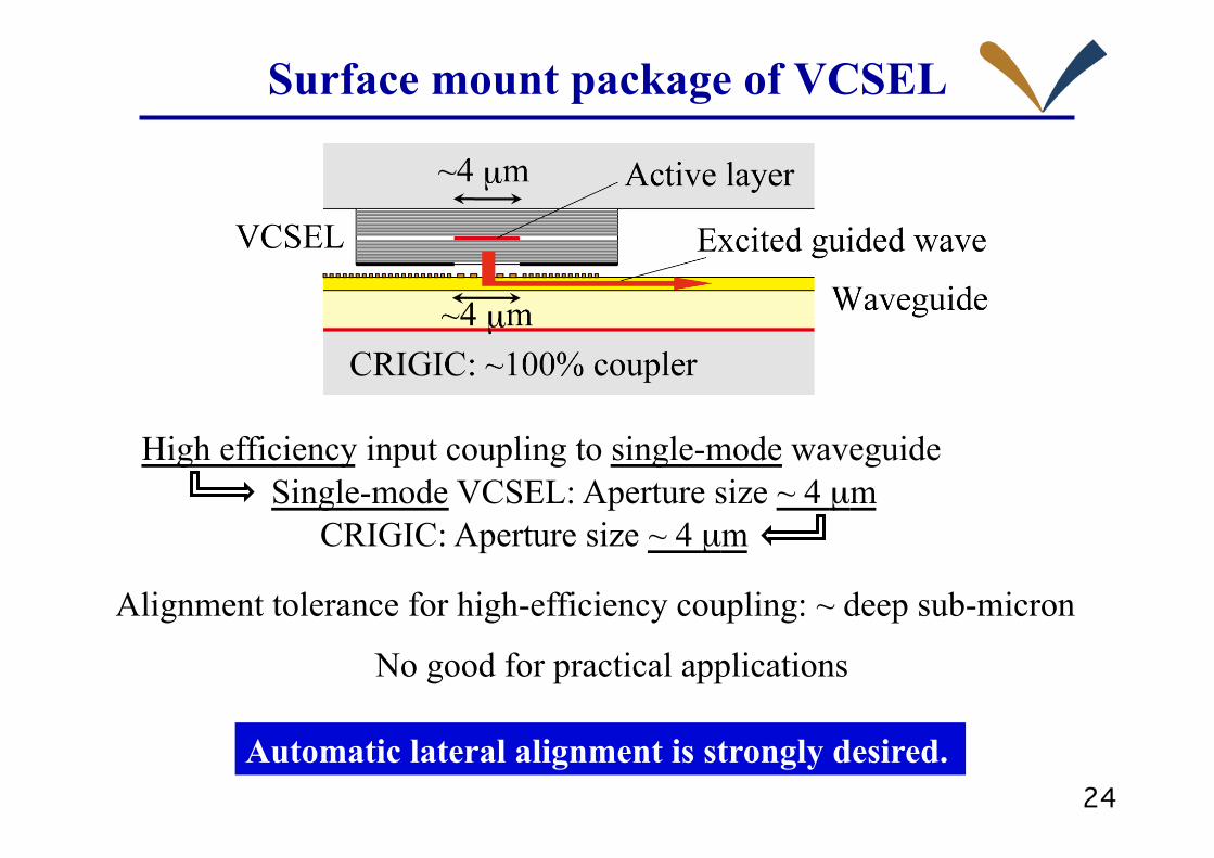
Surface mount package of VCSEL
CRIGIC: Aperture size ~ 4 µm Single-mode VCSEL: Aperture size ~ 4 µm
Alignment tolerance for high-efficiency coupling: ~ deep sub-micron
Automatic lateral alignment is strongly desired.
High efficiency input coupling to single-mode waveguide
No good for practical applications

25�
Concept of advanced packaging Control of VCSEL operation by
a component integrated in photonic circuit board
A larger-aperture half-VCSEL and a smaller integrated mirror may adjust an emission point of VCSEL to mirror position
and relief the alignment problem. Wavelength-selective mirror may provide
wavelength stabilization required in WDM applications.
A problem is mismatch in wavelength between vertical resonance mode and mirror reflection.
26�
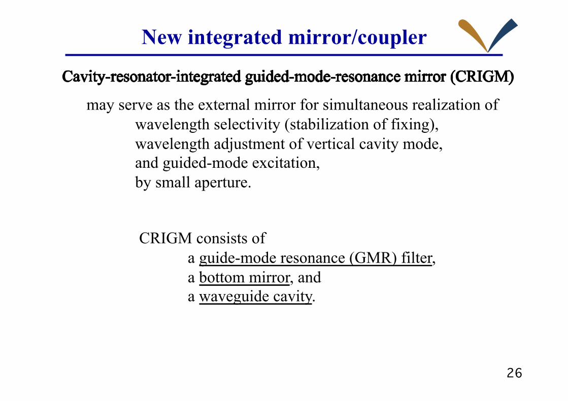
New integrated mirror/coupler
may serve as the external mirror for simultaneous realization of wavelength selectivity (stabilization of fixing), wavelength adjustment of vertical cavity mode, and guided-mode excitation, by small aperture.
CRIGM consists of a guide-mode resonance (GMR) filter, a bottom mirror, and a waveguide cavity.
27�
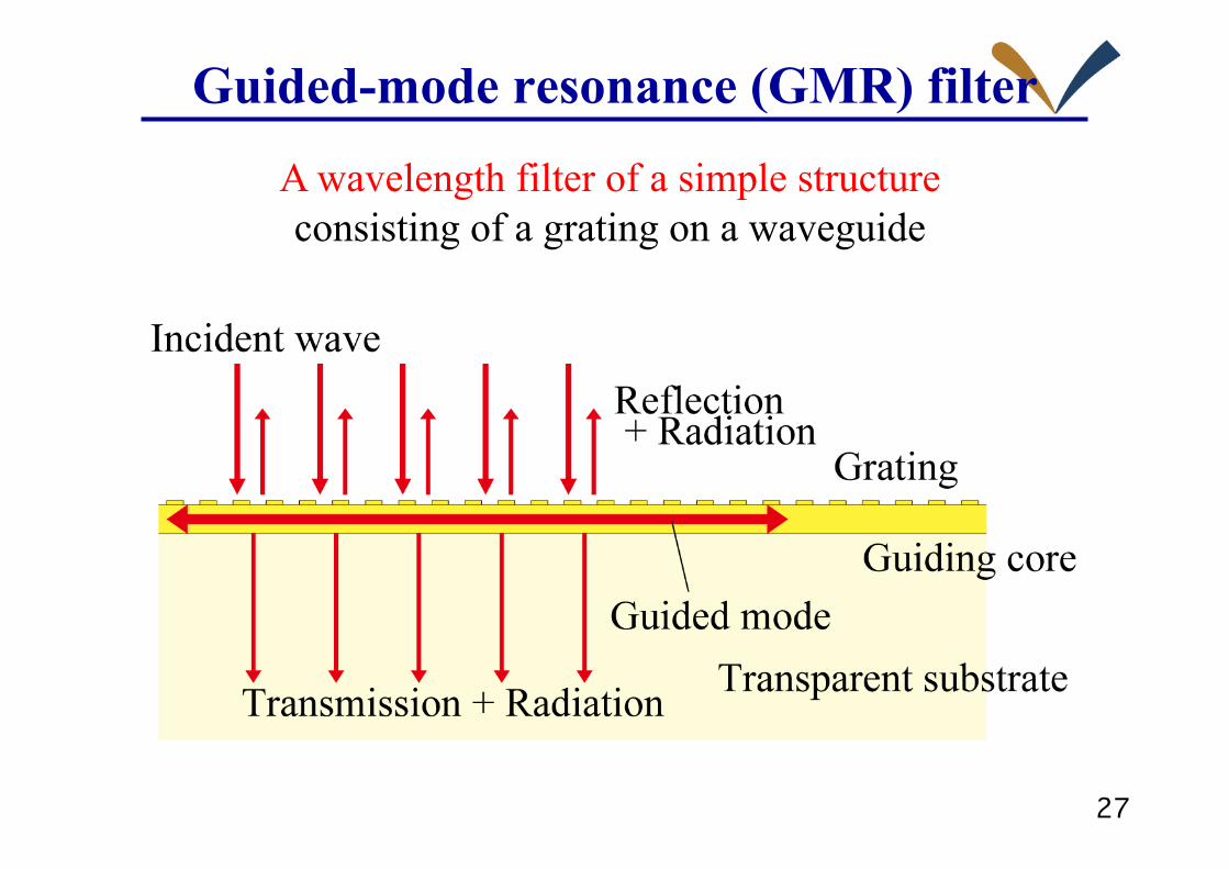
Guided-mode resonance (GMR) filter
A wavelength filter of a simple structure consisting of a grating on a waveguide

28�
Reflection characteristics of GMR filter
Fano resonance of interaction of a continuous state (radiation mode) and a discrete state (guided mode)
Large wavelength dependence of reflection phase attractive for future optical packaging of VCSEL
Narrowband reflection spectrum
29�
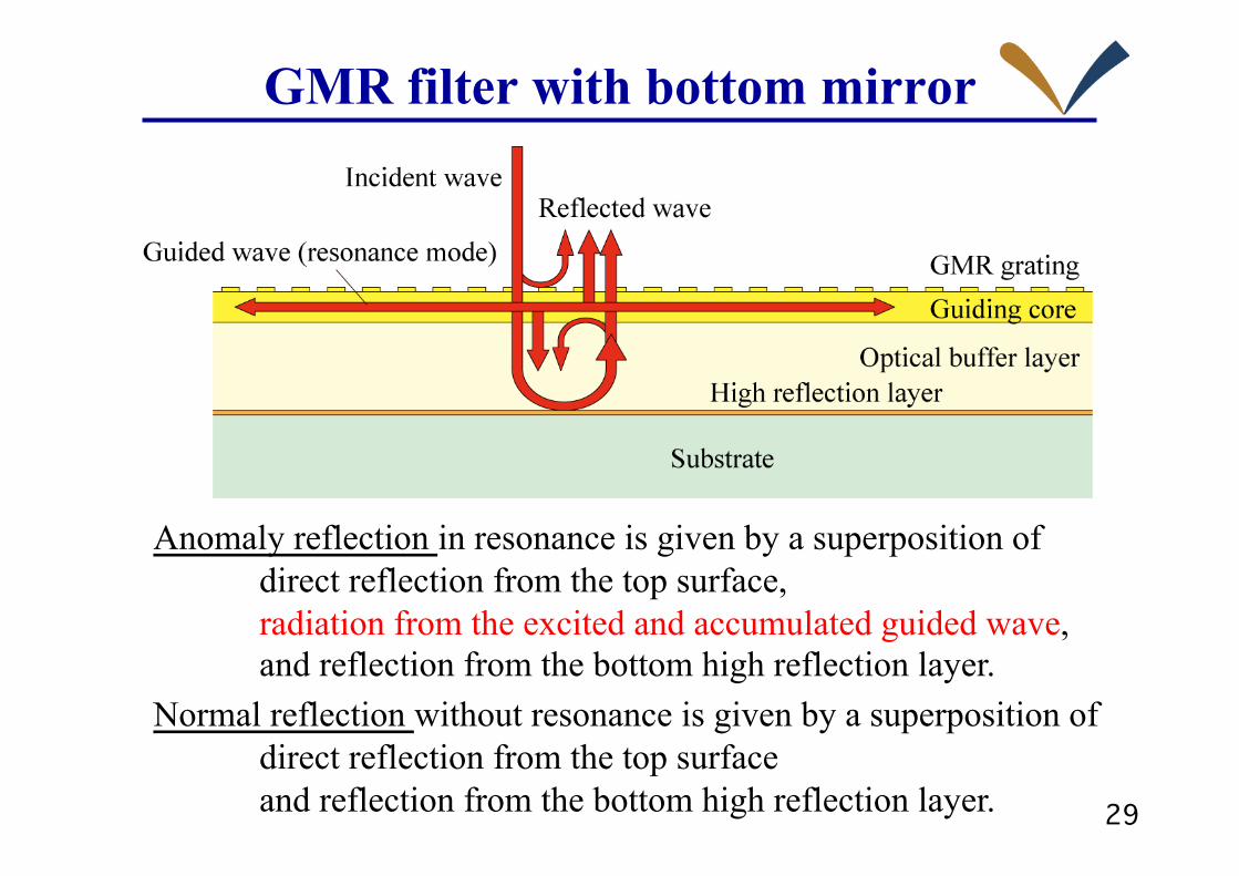
GMR filter with bottom mirror
Anomaly reflection in resonance is given by a superposition of direct reflection from the top surface, radiation from the excited and accumulated guided wave, and reflection from the bottom high reflection layer.
Normal reflection without resonance is given by a superposition of direct reflection from the top surface and reflection from the bottom high reflection layer.
30�
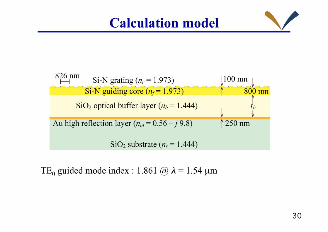
Calculation model
TE0 guided mode index : 1.861 @ λ = 1.54 µm
31�
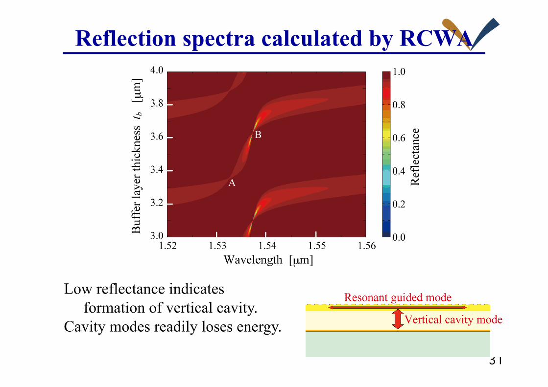
Reflection spectra calculated by RCWA
Low reflectance indicates formation of vertical cavity. Cavity modes readily loses energy.
32�
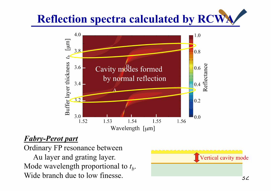
Reflection spectra calculated by RCWA
Cavity modes formed by normal reflection
Fabry-Perot part Ordinary FP resonance between Au layer and grating layer. Mode wavelength proportional to tb. Wide branch due to low finesse.

33�
Reflection spectra calculated by RCWA
Cavity mode formed by anomaly reflection
GMR part Lower dependence of wavelength on tb due to variation of reflection phase. Two anomaly points A & B.

34�
Reflection spectra calculated by RCWA
A: small reflection from GMRF
Reflectance is determined by high reflection layer.

35�
Reflection spectra calculated by RCWA
B: ~100% reflectance from GMRF
High reflectance is from GMR filter.

36�
Reflection spectra calculated by RCWA
Near B: High reflectance from GMRF
High Q of vertical cavity results in large loss and low reflectance.
37�
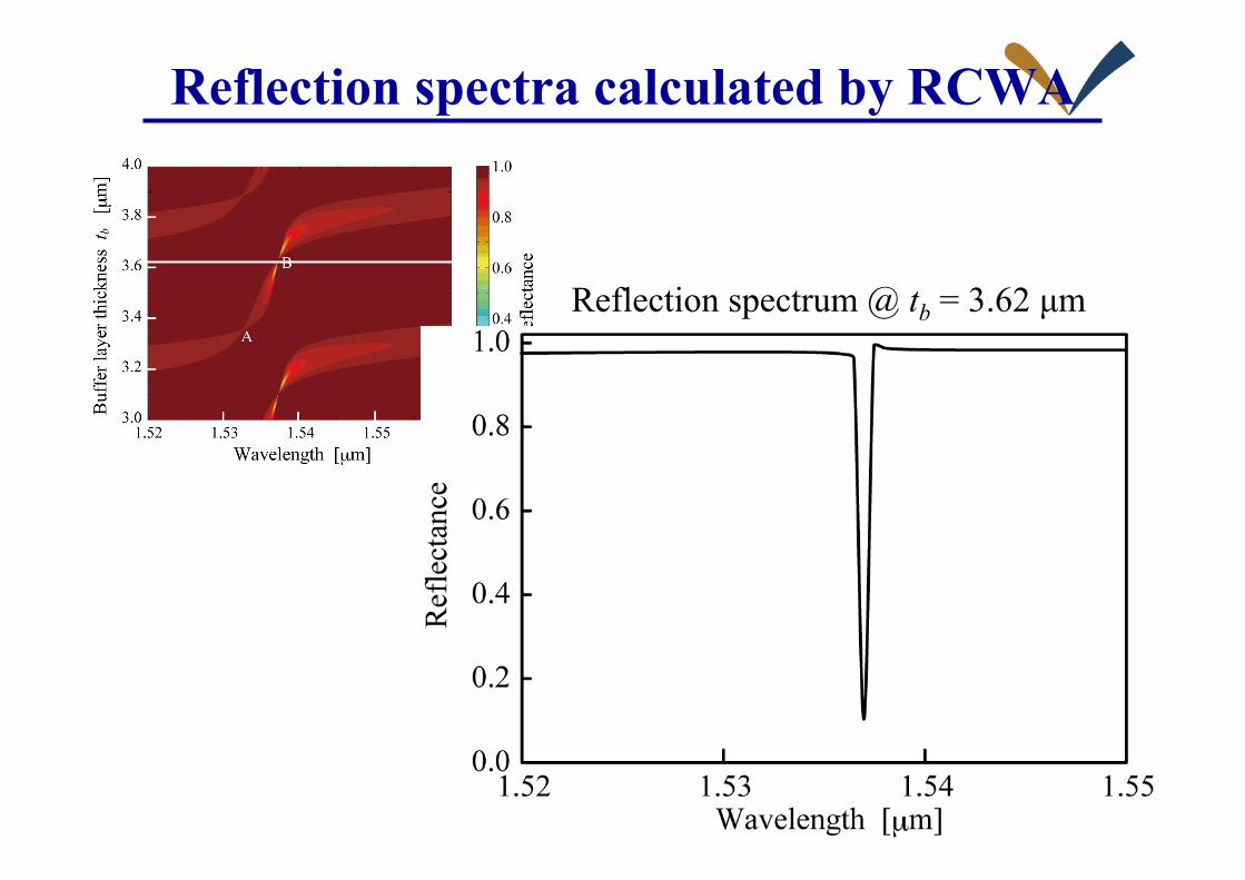
Reflection spectra calculated by RCWA
Reflection spectrum @ tb = 3.62 µm
38�
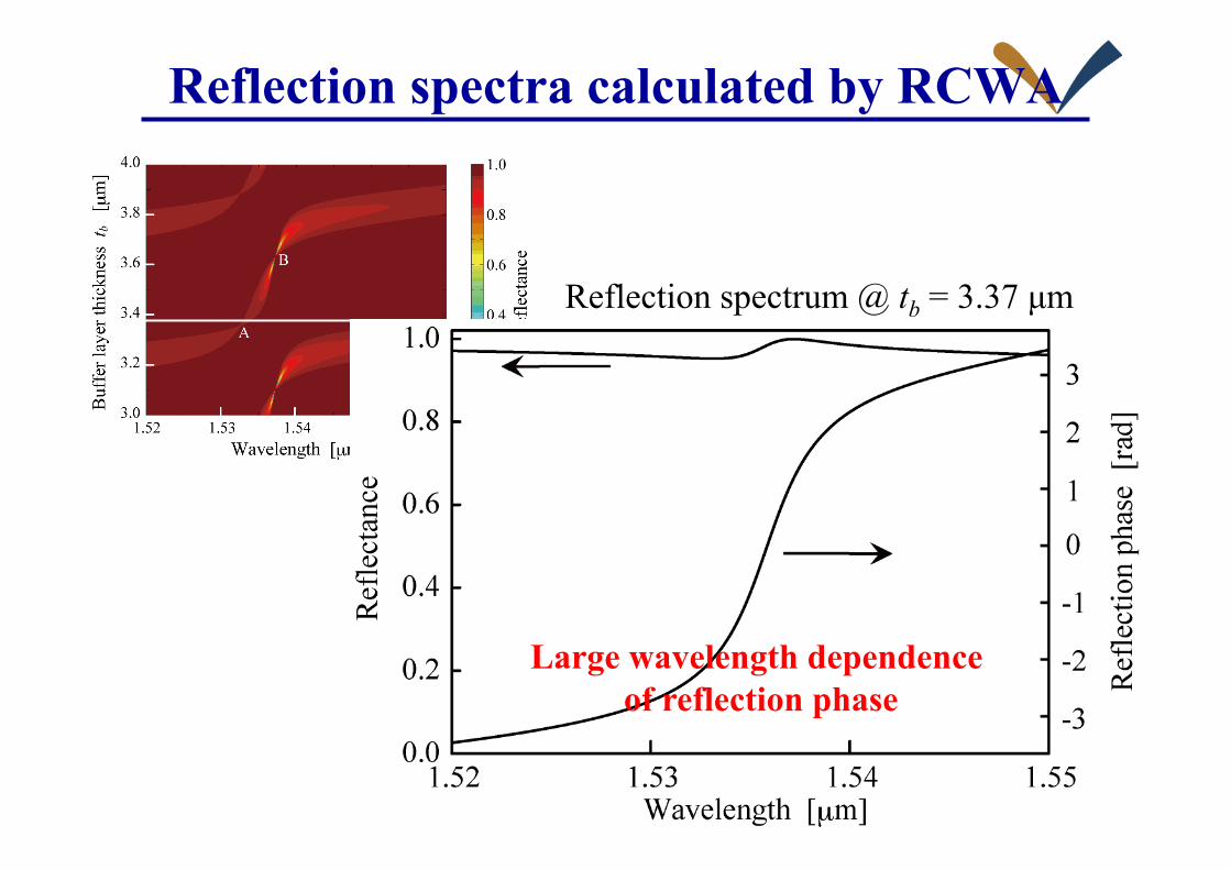
Reflection spectra calculated by RCWA
Large wavelength dependence of reflection phase
Reflection spectrum @ tb = 3.37 µm

39�
Vertical cavity resonance mode
€
2la2πλ−ϕGMRM (λ) −ϕDBR = 2πm (m : Integer)
Wavelength λ of the vertical cavity mode
€
ϕGMRM (λ) : Reflection phase of GMRM
€
ϕDBR : Reflection phase of DBR
€
dλdla
≅laλ
+λ4π
dϕGMRM(λ )dλ
⎛
⎝ ⎜
⎞
⎠ ⎟ −1
Dependence of cavity-mode wavelength λ on air-gap length la

40�
Calculated reflection spectra
Air-gap-length insensitive wavelength-stabilized cavity mode
High reflectance
T. Kondo et al. @ Kyoto Inst. Tech, J. Opt. Soc. Am. A. 32, 1454 (2015)

41�
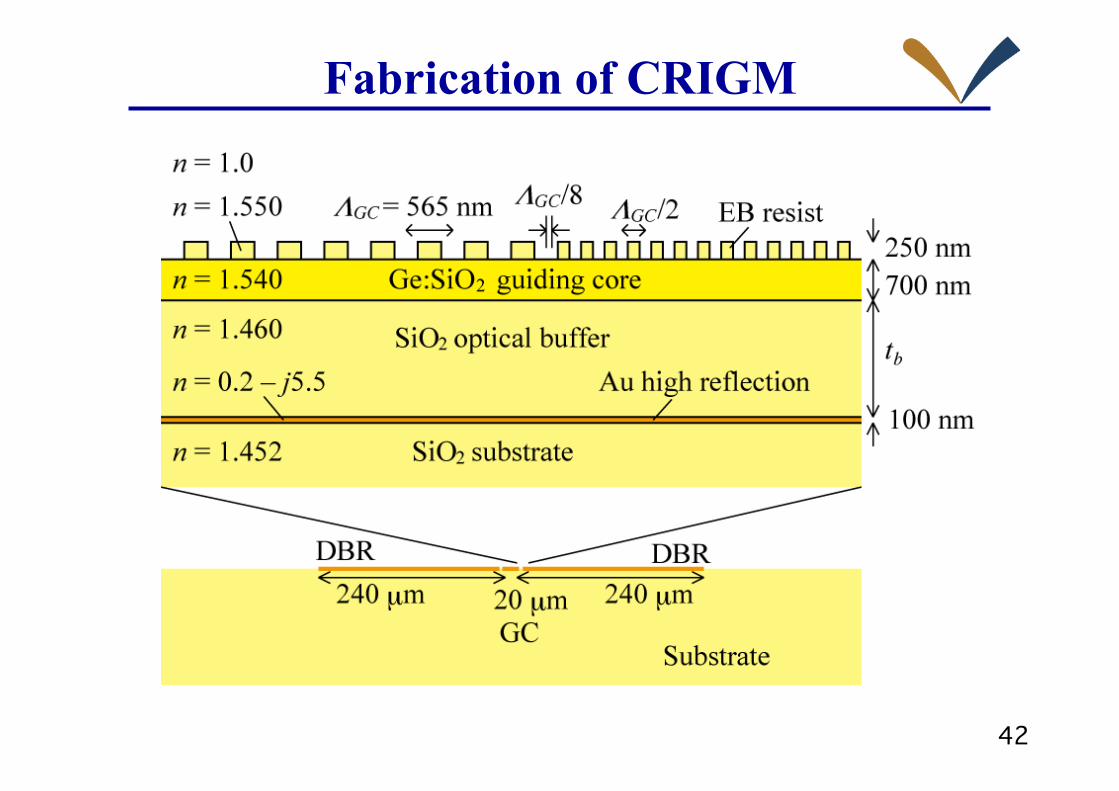
Cavity resonator integration Guided mode resonance filter needs large aperture
for accumulating sufficient guide-mode power to cancel/enhance reflection/transmission.
Aperture miniaturization
Waveguide cavity consisting of a pair of DBRs
42�
Fabrication of CRIGM
43�
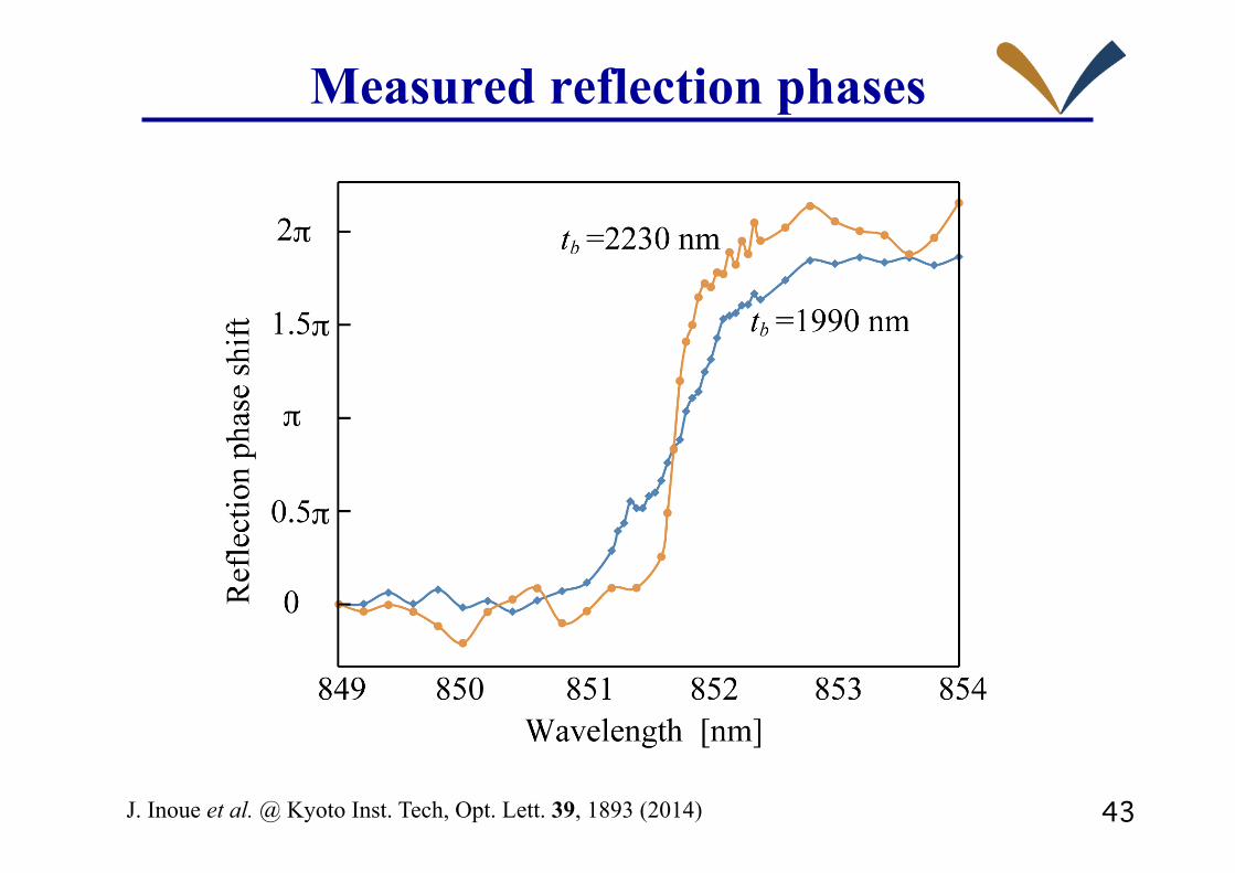
Measured reflection phases
J. Inoue et al. @ Kyoto Inst. Tech, Opt. Lett. 39, 1893 (2014)
44�
Summary
1. A grating coupler (GC) is a powerful coupler for a single mode waveguide,
but is not good at vertical coupling and
needs much larger aperture size in comparison to channel waveguide.
2. Integration of waveguide cavity resonator provides
high-efficiency vertical coupling by small aperture enabling high density.
3. Concept of advanced surface-mount packaging of VCSEL is introduced.
4. Guided-mode resonance is discussed as a unique external cavity mirror
integrated in a single mode waveguide.
This configuration would provide wavelength-stabilization, high-density,
and larger tolerance in VCSEL packaging.

45�
Acknowledgment Kyoto Institute of Technology Dr. J. Inoue, K. Nishio, Y. Imaoka, J. Ohmori, A. Horii, K. Shinoda, T. Kobayashi, S. Murata, T. Ito, Y. Kita, T. Ogura, T. Kondo
National Institute of Advanced Industrial Science and Technology Dr. K. Kintaka
Osaka Prefecture University Prof. H. Kikuta, K. Kameda, Y. Minamino, S. Oue, D. Yamashita
The University of Texas at Arlington Prof. R. Magnusson
Fujitsu Laboratories Dr. K. Yokouchi, Dr. M. Katoh, Dr. A. Sugama


