JOURNAL OF THE OPTICAL SOCIETY OF AMERICA Optical Transfer Properties of Fiber Bundles* RENEE DROUGARD IBM Watson Research Center, Yorktown Heights, New York 10598 (Received 20 November 1963) The point spread function of a static fiber bundle is not spatially invariant, and the system cannot there- fore be strictly characterized by an optical transfer function. It is shown both theoretically and experi- mentally that, in the case of circular fibers of diameter d, the modulation of the image of an object varies with the position of the fiber bundle and lies between two extreme values which become closer together as the spatial frequency decreases. Thus, for sufficiently low frequencies (of the order 1/8d), an optical transfer function can be used. The experimental results are in good agreement with the theory. A randomly vibrating bundle is found to have a spatially invariant point spread function and can therefore be characterized by an optical transfer function. I. INTRODUCTION D URING the last few years, fiber optics has proved to be a useful tool in several branches of tech- nology. The transmission properties and geometrical optical properties of single fibers and fiber bundles have been studied.1- 3 The waveguide properties of very small diameter fibers have been well described by Snitzer. 4 However, little has been done about their optical transfer properties, although the method of Fourier analysis has proved to be a powerful tool in evaluating the performance of other optical systems. The image of an object given by a bundle of identical circular fibers on a photographic plate has been studied by Kapany el al.,1- 7 in two cases: that of a fixed fiber bundle ("static" image), and that of a randomly moving fiber bundle ("dynamic" image). To explain his results, Kapany adopted as a"dynamic" modulationt transfer function of the fiber bundle T(v) = 2f 1 (irvd)/7rvd, (1) in which Jl is the Bessel function of the first kind of the first order, v is the spatial frequency, and d is the diameter of one fiber. He was, however, unable to verify experimentally the negative modulation pre- dicted by Eq. (1). He states further that for a perfect fiber bundle without light leakage, "The dynamic point spread function is a bell-shaped function with two fiber diameter width." Since Eq. (1) implies that the "dynamic" point * This paper was presented at the Meeting of the Optical So- ciety of America, Jacksonville, Florida, March 1963. 1R. J. Potter, Ph.D. thesis, "A Theoretical and Experimental Study of Optical Fibers", University of Rochester, Rochester, New York, 1960. 2 R. J. Potter, J. Opt. Soc. Am. 51, 1079 (1961). N. S. Kapany Concept of Classical Optics, edited by J. Strong (W. H. Freeman and Company, San Francisco, 1958). E. Snitzer, J. Opt. Soc. Am. 51, 491 (1961). N. S. Kapanv, J. A. Elyer, Rt. E. Keim, J. Opt. Soc. Am. 17, 423 (1957). N. S. Kapany, J. Opt. Soc. Am. 49, 770 (1959). N. S. Kapany, J. Opt. Soc. Am. 49, 779 (1959). t In accordance with the announcement in the Editor's Page it the January 1964 issue of this journal (p. 146), the editor has replaced everywhere in the text the word contrast by modulation. spread function is constant inside a circle of diameter d and zero outside, there is an obvious discrepancy between the two statements, which was noticed by Roetling and Ganley.A They suggested that the con- sideration of the complete system, including both ends of the fibers moving with respect to the object and the photographic plate, might lead to the "dynamic" transfer function r(v>) [2J (rvd)/1rvd] 2 , (2) which would be in agreement with the absence of negative modulations and with a dynamic point spread function having a "two fiber diameter width." This formula is consistent with the simple fact that the entry face of the fiber is a scanning aperture and that the exit face then acts as a "writing aperture," each having a transfer function of the form of Eq. (1). Further study of this question seems to be needed and, in particular, the first problem which must be looked into is the applicability of the concepts of point spread function and modulation transfer function to fiber bundles. II. THEORETICAL STUDY It is intuitively obvious that fiber bundles are not capable of giving a faithful image of an object which has a spatial period smaller than the diameter of fibers. There is therefore little reason, when considering fiber bundles, to concern oneself about the exact shape of the point spread function of a single fiber. However, the published literature is somewhat ambiguous on this point. Experimentally, it is found that if the illuminance on the entrance face is of slow variation and does not exhibit any discontinuities, the illuminance of the exit face appears quite uniform, and this will be the starting point of our discussion. This is not the same as assuming the fiber to have a point spread function in the proper sense of the term. 8 P. C. Roetling a1(n W. P. Ganlev, J. Opt. Soc. Am. 52, 99 (1962). 907 JULY 1964 VOLUME 54, NUMBER 7
Transcript
JOURNAL OF THE OPTICAL SOCIETY OF AMERICA
Optical Transfer Properties of Fiber Bundles*
RENEE DROUGARD
IBM Watson Research Center, Yorktown Heights, New York 10598(Received 20 November 1963)
The point spread function of a static fiber bundle is not spatially invariant, and the system cannot there-fore be strictly characterized by an optical transfer function. It is shown both theoretically and experi-mentally that, in the case of circular fibers of diameter d, the modulation of the image of an object varieswith the position of the fiber bundle and lies between two extreme values which become closer together as thespatial frequency decreases. Thus, for sufficiently low frequencies (of the order 1/8d), an optical transferfunction can be used. The experimental results are in good agreement with the theory. A randomly vibratingbundle is found to have a spatially invariant point spread function and can therefore be characterized byan optical transfer function.
I. INTRODUCTION
D URING the last few years, fiber optics has provedto be a useful tool in several branches of tech-
nology. The transmission properties and geometricaloptical properties of single fibers and fiber bundles havebeen studied.1-3 The waveguide properties of verysmall diameter fibers have been well described bySnitzer. 4 However, little has been done about theiroptical transfer properties, although the method ofFourier analysis has proved to be a powerful tool inevaluating the performance of other optical systems.
The image of an object given by a bundle of identicalcircular fibers on a photographic plate has been studiedby Kapany el al.,1- 7 in two cases: that of a fixed fiberbundle ("static" image), and that of a randomlymoving fiber bundle ("dynamic" image). To explainhis results, Kapany adopted as a"dynamic" modulationttransfer function of the fiber bundle
T(v) = 2f 1 (irvd)/7rvd, (1)
in which Jl is the Bessel function of the first kind of thefirst order, v is the spatial frequency, and d is thediameter of one fiber. He was, however, unable toverify experimentally the negative modulation pre-dicted by Eq. (1). He states further that for a perfectfiber bundle without light leakage, "The dynamic pointspread function is a bell-shaped function with twofiber diameter width."
Since Eq. (1) implies that the "dynamic" point
* This paper was presented at the Meeting of the Optical So-ciety of America, Jacksonville, Florida, March 1963.
1 R. J. Potter, Ph.D. thesis, "A Theoretical and ExperimentalStudy of Optical Fibers", University of Rochester, Rochester,New York, 1960.
2 R. J. Potter, J. Opt. Soc. Am. 51, 1079 (1961).N. S. Kapany Concept of Classical Optics, edited by J. Strong
(W. H. Freeman and Company, San Francisco, 1958).E. Snitzer, J. Opt. Soc. Am. 51, 491 (1961).N. S. Kapanv, J. A. Elyer, Rt. E. Keim, J. Opt. Soc. Am. 17,
423 (1957).N. S. Kapany, J. Opt. Soc. Am. 49, 770 (1959).N. S. Kapany, J. Opt. Soc. Am. 49, 779 (1959).
t In accordance with the announcement in the Editor's Page itthe January 1964 issue of this journal (p. 146), the editor hasreplaced everywhere in the text the word contrast by modulation.
spread function is constant inside a circle of diameter dand zero outside, there is an obvious discrepancybetween the two statements, which was noticed byRoetling and Ganley.A They suggested that the con-sideration of the complete system, including both endsof the fibers moving with respect to the object and thephotographic plate, might lead to the "dynamic"transfer function
r(v>) [2J (rvd)/1rvd]2 , (2)
which would be in agreement with the absence ofnegative modulations and with a dynamic pointspread function having a "two fiber diameter width."This formula is consistent with the simple fact thatthe entry face of the fiber is a scanning aperture andthat the exit face then acts as a "writing aperture,"each having a transfer function of the form of Eq. (1).
Further study of this question seems to be neededand, in particular, the first problem which must belooked into is the applicability of the concepts ofpoint spread function and modulation transfer functionto fiber bundles.
II. THEORETICAL STUDY
It is intuitively obvious that fiber bundles are notcapable of giving a faithful image of an object whichhas a spatial period smaller than the diameter offibers. There is therefore little reason, when consideringfiber bundles, to concern oneself about the exact shapeof the point spread function of a single fiber. However,the published literature is somewhat ambiguous onthis point. Experimentally, it is found that if theilluminance on the entrance face is of slow variation anddoes not exhibit any discontinuities, the illuminanceof the exit face appears quite uniform, and this will bethe starting point of our discussion. This is not thesame as assuming the fiber to have a point spreadfunction in the proper sense of the term.
8 P. C. Roetling a1(n W. P. Ganlev, J. Opt. Soc. Am. 52, 99(1962).
907
JULY 1964VOLUME 54, NUMBER 7
RENEE DROUGARD
A. Randomly Vibrating Fiber Bundle-Dynamic Image
Let us consider a fixed object, the illuminance ofwhich, at one point x, y in its plane, is represented by anintegrable function f (x,y). Let us suppose that thisobject is scanned by one circular fiber moving inrandom directions, and let x', y' be the coordinates ofthe center of the exit face of the fiber, measured withrespect to the x, y axes of the object plane.
The illuminance over the exit face of the fiber willbe equal to the average of the illuminance falling onthe entrance face. Thus, the illuminance over the exitface of the fiber, when its center is at the point x', y',is given by
f' (',y') = J f(x,y)dxdy, (3)
in which the integration extends over the entrance faceof the fiber. R is the radius of the fiber. Equation (3)may be usefully written:
1 r+f'(x'y') = f(xy)e(x'-x, y'-y)dxdy, (3')
with
e(x'-x, y'-y)= 1 for (xI-X)2+ (y'-y) 2<R2,
1 = 0 elsewhere.
The function e(x',y') centered on (x,y) is equal tounity inside a circle of radius R and is zero outside.The Fourier transform of this function appears insubsequent formulas. The function f' (x',y') now appearsin the form of a convolution of the function f(x,y)representing the object, and the function e(x',y')/7rR2 .Thus, if we define the function f'(x'y') as the image ofthe object, Eq. (3') defines e(x',y')/7rR2 as the pointspread function of the scanning fiber, and it impliesthat the system is linear, and spatially invariant. Itshould be emphasized that Eq. (3') does not implyanything about what the image of one point really is;it defines mathematically a fictitious point spreadfunction for the fictitious "image" f'(x',y').
For this "image" defined by f'(x',y'), for anyposition x', y' of the fiber, it is possible to speak of anormalized optical transfer function given by theFourier transform of the function e(x',y')/7rR2
T (v)= 2J I(7r vd) /7r vd,
T(v) being the transfer function supposed by Kapanvto hold for his "dynamic" image. It is quite clear thatthis trainsfer function is, in fact, valid only for thefictitious "image" f'(x',y'), defined by Eq. (3'). Thecase of the moving fiber wil now be examined.
Let us suppose that a stationary photographic plateis located in the plane of the exit face and that the
fiber moves in all directions. In each position, the fiberilluminates uniformly a circle on the plate. Thisilluminance varies with the position of the fiber and issimply f'(x',y'). At a fixed point of the plate, theilluminance in the image which is recorded will be thetime integral of this varying illuminance from themoving fiber. When the center of the fiber is at (x',y'),the illuminance of the point x", y" of the plate is givenby
f '(xy')e(x"- x', y"-y'),the level of illuminance inside is given by f'(x',y') andis zero outside the fiber aperture, described here bythe aperture function e(x",y") centered on x',y'.
If now the fiber moves, such that the point x",y"on the plate is exposed to each point on the fiber exitface for the same length of time (as long as the platemay be considered as a linear system), the integratedilluminance will be given by:
This condition is clearly satisfied for the case of uniformmotion, and also for suitably random motion. It is ofcourse necessary that the total range of motion be atleast equal to two fiber diameters. Equation (4) thendescribes the image on the plate; e(x"-x', y"-y') isagain the fiber aperture defined in Eq. (3').
We replace in Eq. (4), f'(x',y') by its expression inEq. (3'), to obtain:
fr (x",y") =- f(x,y) e(x'-x, y'-y)irR2 J
Xe(x" -x', y" -y')dx'dy'dxdy, (5)
in which the integrals are taken over the entire planesx', y' and x, y. We note that the inner integral
J| e(x'- x, y'-y)e(x"- x', y"-y')dx'dy',
may be written in terms of the autocorrelation functionof e(x,y), namely:
E(a,3) = J e(s,t)e(a-s, 13-s)dsdi. (6)
Thus, putting s=x'-x, I= y'-y; and a=x"-x,B= y"-y; we may write Eq. (5) in the form of aconvolution of the original object with a spread function:
f"(.I", ") - xJ+Z "-x, v"-t)f(xvt)dxdy. (7)
Equation (7) shows that, in the case of a randomly
908 Vol. 54
OPTICAL TRANSFER OF FIBER BUNDLES 0
moving fiber, there exists a point spread functiondefined by the autocorrelation function E(x",y")17rR2 .It is then possible to speak of a modulation transferfunction, which is the Fourier transform of this function,namely:
r (v) [= 2J1 (7rvd )/7rvd]2
As previously mentioned, this result has been suggestedby Roetling and Ganley 8 on a semi-intuitive basis.The spread function E(x"- x, y"-y) emerging from thisanalysis has circular symmetry, and is the autocorrelationfunction of the function e(x" y") which is constant insidea circle of diameter d and zero outside. Its shape is wellknown.
The results obtained in the case of one randomlymoving fiber obviously apply to the case of a wholefiber bundle of well-coated fibers, merely by using thetrivial result that the transform of the sum of partialfunctions is the sum of the partial transforms.
B. Stationary Fiber Bundle
The bundle will be assumed to be made of N identical,faultless, circular, well-coated fibers, with a hexagonalclose-packed section. The thickness of the coating willbe neglected.
The intensity at a point x", y" of the exit face canbe written down immediately by analogy with thepreceding case. The only difference is that the centersof the fibers x', y' are not allowed to move aboutcontinuously but instead occupy discrete positions,Xi', yi'. The integration over x'y' in Eq. (5) is nowsimply replaced by a summation over xi', yi' to yield
f" (x",Y") R2 5 7 f(x,y)e(x,'-x, y,'-y)
Xe(x"-xi', y"-yi')dxdy, (8)
in which, for any value of (x",y") there can be no morethan one nonzero term in the summation, since onlyone fiber may cover any given point. Equation (8)can be written in the form of convolution of f(x,y)and of a function
E' = a, i e (x'- x, yi'- y)e (x" -xi', y-yi') . (9)
The function E' thus defined can be called a point spreadfunction but it must be emphasized that E' is not spatiallyinvariant. It goes, in fact, through rather wild fluctua-tions, since a point located between fibers yields noimage. It is therefore impossible in principle to describethe optical transfer properties of a fiber bundle by meansof an optical transfer function depending only on thespatial frequency v.
If the fiber bundle is used to form an image of anobject, the shortest spatial period of which is much
larger than the diameter of the fibers, the fiber structurewill be present in the image, but still the object willbe perfectly recognizable. In the limit of very largeobject periods, the fiber bundle can obviously beconsidered as having a spatially invariant point spreadfunction, namely a a function and an optical transferfunction which is unity.
In the general case, the modulation transfer functionof the system is expected, for a given object frequency,to be spatially dependent, i.e., to vary with a rotation ortranslation of the fiber bundle. It is, however, of muchpractical interest to know between what limits it varies,whether its minimum value is acceptable and whetherits variations are not too large.
Consider a periodic object having illuminancef (x,y) = a+b cos27rvx, and modulation CO= b/a. In aclassical system of unity magnification (with a spatiallyinvariant point spread function), the image would begiven by
ff'(x',y') = a+bM(v) cos[2i7rvx'+0 (v)], (10)
omitting an irrelevant photometric constant. Here,M(v) and ¢(v) are the modulus and phase of the opticaltransfer function.
The illuminance distribution in an image given by afiber bundle is more complicated than Eq. (10) in anumber of ways. First, f'(x',y') is not independent of y'.A first approximation consists of neglecting the modu-lation along the y' direction (and thus possible spuriousfrequencies whose importance will have to be evaluatedlater). In this approximation, the image is characterizedby a function f' (x') which is the average of the functionf'(x',y') along a vertical line covering a large numberof fibers.
Even then the definition of the modulation remains aproblem: f'(x') is a pseudo periodic function involvingthe periodicity of the object and a modulation due tothe fiber structure. This modulation is periodic, ofperiod p (see appendix). That is, if a line L covering alarge number of fibers is given a translation p, itperiodically covers the same arrangement of fibers. Theperiod p depends on the orientation of the fiber bundle.
A reasonable definition for the modulation of thefunction f'(x') is certainly expected to predict a zeromodulation for the image of a uniform object (whichshows only the periodicity of the fiber structure). Wenote, however, that in this case of a uniform object, andbecause of the periodicity of the fiber structure, we have,k being an integer:
f' (x'+kp) = f'(x'), (11)
and hence a sampling of the image of period p does leadto the desired result of zero modulation.
In a similar way, when the frequency v of the objectis different from zero, it will be shown presently thatthe points f'(xo'+kp) fall in the same sine curve (seeFig. 1) of spatial frequency v. To calculate f'(x'), we
9()9Jully 1964
10 l R N E' E D Ro tT G o l. 5
f (x')I - 2 v
N I
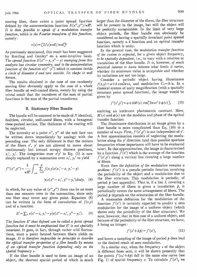
FIG. 1. The function of f'(x') representing the image of a sinewave object through a static fiber bundle, shows the periodicityi/v of the object and the periodicity p of the fiber structure. Anyseries of points f'(xo'+kp), k integer, falls on a same sine curve(clotted line).
consider a straight line L parallel to the y' axis and ofabscissa x'. It crosses N fibers (N very large) whichgenerally do not contribute the same amount of light.If x,' is the abscissa of the center of the nth fiber crossedby L, and hIn the algebraic distance to L of this center,so that x'+ht2 =x,/, the illuminance at any point ofthe exit face of the nth fiber is proportional to: [SeeEq. (10) and Part II, Sec. A]
a+bT(v) cos2rv(x'+/zt), (1z,<R),
and the contribution of the nth fiber is proportional tothe length crossed by L, hence omitting a constantfactor,
f' (x') = E (R21-,, 2)1[a+bT(,) cos27rv(x'+/z,,)]. (12)nil
This is the sum of N sinusoidal functions of the sameperiod, same modulation, but of different phases. Theresult is a sinusoidal function of the same period, whichmay be written
f '(x') =A +B cos27rv(x'+HI), (13)
with
NA =a E (R2 -hz,,2), and
1-1
N<•bT(v) _ (R2 -1z 2)'.
-I l
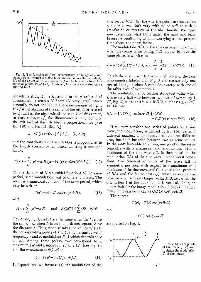
Obviously, A, B, and II are the same when the has's arethe same, i.e., when L is on the positions separated bythe distance p. Thus, when x' takes the values xo'+kp,the corresponding points of f'(x') fall on a sine curve offrequency v and of modulation B/IA which depends onlyon xo'. Among these points, two correspond to amaximum fJ,,' and a minimum fmt of f'(x') (see Fig. 2),and the modulation is dcfincd as:
sine curve, BI/A; (b) the way the points are located onthe sine curve. Both vary with x0' as well as with atranslation or rotation of the fiber bundle. We mustnow determine what Ci is under the most and leastfavorable conditions, without worrying at the presenttime about the phase factor.
The modulation B1 A of the sine curve is a maximumwhen all cosine terms of Eq. (12) happen to have thesame phase, in which case
N B bB bT(v) E (R2-Iz, 2)', and -T(v) = CoT(v). (15)
7 1 yA a
This is the case in which L is parallel to one of the axesof symmetry labeled I in Fig. 3 and crosses only onerow of fibers, or when L coincides exactly with one ofthe other axes of symmetry II.
The modulation B/A reaches its lowest value whenL is exactly half-way between two axes of symmetry I(I', Fig. 3), so that all h,,= 4Rv0i2, all phases i±7rvRW3.In this case:
B/A={JNbT(v) cos(7rvRV3)}/ (Na)
=CoT(v) cos(7rvRv34) (16)
If we now consider one series of points on a sinewave, the modulation, as defined by Eq. (14), varies ifdifferent maxima and minima are taken on differentarcs, but it is included between two extreme values.In the most favorable condition, one point of the seriescoincides with a maximum and another one with aminimum of the sine wave; Ci is then equal to themodulation B/A of the sine wave. In the worst condi-tions, two consecutive points of the series fall insymmetric positions with respect to a maximum or aminimum of the sine wave, and Ci is equal to the productof B/A and the factor cos(7rvp), which is as small aspossible when p has its largest value RV3, i.e., when theorientation I of the fiber bundle is vertical. Thus, anupper limit for the image modulation C0 is CoT(v) and alower limit can be taken as CoT(P) cos2(7rvRV3).
The curves
T(P), T(v) cos(7rvR-C)
and
T(v) cos2 (7rRv3)
are plotted on Fig. 4.
fM
(14) fm
I
- P F-
FIG. 2. Series of pointsof the image f'(x') usedto define the modulationCi of the image.
It depends on two factors: (a) the modulation of the
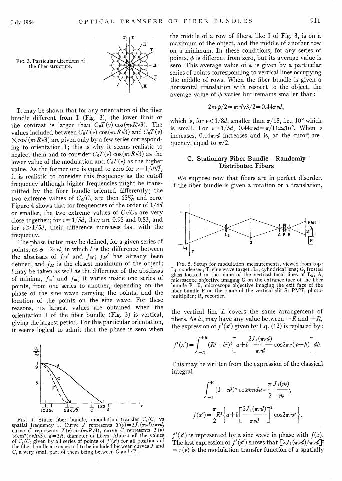
It may be shown that for any orientation of the fiberbundle different from I (Fig. 3), the lower limit ofthe contrast is larger than CoT(v) cos(7rvRV3). Thevalues included between CoT(i) cos(7rvRV3) and CoT(v)X cos2 (7rvRVC) are given only by a few series correspond-ing to orientation I; this is why it seems realistic toneglect them and to consider CoT(v) cos(7rvRA3) as thelower value of the modulation and CoT(v) as the highervalue. As the former one is equal to zero for v= 11dV3,it is realistic to consider this frequency as the cutofffrequency although higher frequencies might be trans-mitted by the fiber bundle oriented differently; thetwo extreme values of CilCo are then 65% and zero.Figure 4 shows that for frequencies of the order of 1/8dor smaller, the two extreme values of Ce/Co are veryclose together; for v= 1/5d, they are 0.95 and 0.83, andfor v> 1/5d, their difference increases fast with thefrequency.
The phase factor may be defined, for a given series ofpoints, as 4) = 27rvl, in which I is the difference betweenthe abscissas of fM' and fM; f'r has already beendefined, and IM is the closest maximum of the object;I may be taken as well as the difference of the abscissasof minima, fin' and fm; it varies inside one series ofpoints, from one series to another, depending on thephase of the sine wave carrying the points, and thelocation of the points on the sine wave. For thesereasons, its largest values are obtained when theorientation I of the fiber bundle (Fig. 3) is vertical,giving the largest period. For this particular orientation,it seems logical to admit that the phase is zero when
.9
.5 J'C
I I II 1 1.22 1IOd5d 2d d./3 d d
FIG. 4. Static fiber bundle, modulation transfer Gd/Co vsspatial frequency v. Curve J represents T(v)=2J1(7rvd)/7rvd,curve C represents T(v) cos(7rvRV3), curve C represents T(v)Xcos2 (7rvRx0). d=2R, diameter of fibers. Almost all the valuesof Ce/Co given by all series of points of f'(x') for all positions ofthe fiber bundle are expected to be included between curves J andC, a very small part of them being between C and C'.
I',
911July 1964 OPTICAL
the middle of a row of fibers, like I of Fig. 3, is on amaximum of the object, and the middle of another rowon a minimum. In these conditions, for any series ofpoints, 0 is different from zero, but its average value iszero. This average value of 4 is given by a particularseries of points corresponding to vertical lines occupyingthe middle of rows. When the fiber bundle is given ahorizontal translation with respect to the object, theaverage value of 4 varies but remains smaller than:
27rvp/2 = rvdV3i2 = 0.447rvd,
which is, for v< 1/8d, smaller than 7r/18, i.e., 100 whichis small. For v= 1/5d, 0.447rvd=7r/11-16'. When vincreases, 0.447r'd increases and is, at the cutoff fre-quency, equal to 7r/2.
C. Stationary Fiber Bundle-RandomlyDistributed Fibers
We suppose now that fibers are in perfect disorder.If the fiber bundle is given a rotation or a translation,
T
FIG. 5. Setup for modulation measurements, viewed from top:Li, condenser; T, sine wave target; L 2, cylindrical lens; G, frostedglass located in the plane of the vertical focal lines of L 2 ; A,microscope objective imaging G on the entrance face of the fiberbundle F; B, microscope objective imaging the exit face of thefiber bundle F on the plane of the vertical slit S; PMT, photo-multiplier; R, recorder.
the vertical line L covers the same arrangement offibers. As ha may have any value between -R and +R,the expression of f'(x') given by Eq. (12) is replaced by:
r+R r 2JI(17rd)f (x')=I (R2_ 12) [a+b3 cos2irv(x+hl)]dA.
-R I rvd
This may be written from the expression of the classicalintegral
r+ Xr Js(Mn)(I (- P) Icosmudu =-
-1 2 in
2J 2 I(7rvd) 2
f(x' =-R2 2a+b[ ] cos27rvx'
f'(x') is represented by a sine wave in phase with f(x).The last expression of f'(x') shows that [2J1 (7rvd)/7rvd]2
= r (v) is the modulation transfer function of a spatially
,,
91 RENEE DROUGARD
invariant system. Of course, this is true as long as thefibers may be considered randomly distributed. Thisimplies a large number of fibers, and the result cannotbe considered valid for frequencies of the order of 1/d.The approximation is better for lower frequencies.The function r(v) is included between T(v) andT(v) cos(7rvR'3) and the three of them are closertogether as the frequency decreases (see Fig. 4). In abundle of nonordered fibers, perfect disorder does notexist. There are some areas of ordered fibers, thus it isbetter to consider the worst value of the modulationtransfer T(v) cos(7rvRv3) and of the average phase0.447rvd.
D. Conclusions of the Theoretical Study
The modulation Ci of the image of a sine wave objectby a stationary fiber bundle has been defined [Eq. (14)]with the help of different series of points of the functionf'(x') representing the image. Almost all the valuesof the modulation transfer Cl/C0 given by all series ofpoints of f'(x') for all positions of the fiber bundle areexpected to be included between the two curves J andC of Fig. 4, a very small part of them being betweenC and C'. For v< 1/8d, the modulation transfer Cf/Cois greater than 90%, the average phase is smaller than10°; thus we may expect a very good image.
We may still consider the image as acceptable whenv= 1/5d, but for v< 1/5d, the drawbacks of the fiberbundle become more apparent. The difference betweenthe two extreme values of C2/Co increases rapidly withv, the average phase becomes important, and themodulation of light along a vertical line is less and lessnegligible, and it does not seem reasonable to expect agood image.
III. EXPERIMENTS
Experiments have been performed only in the caseof the stationary fiber bundle. Referring to Fig. 5,collimated light from a sodium lamp is focused by aconverging lens L1 through a variable area sine wavetarget T running in the horizontal direction. A cylin-drical lens L2 with vertical axis forms a pseudoimageof the target on a piece of frosted glass G located in theplane of the vertical focal lines of L2. This pseudoimageacts for the rest of the system as a light source ofsinusoidally varying luminance, the lines of equalluminance being vertical. A microscope objective Aforms a reduced image of G on the entrance face of thefiber bundle F. A second microscope objective B,identical to A, gives an enlarged image of the exitface of the fiber bundle. Illuminance measurements arecarried out with a photomultiplier PMT having avertical entrance slit S in the plane of the image of theexit face of the fibers. The slit is of such dimensions thatit receives the light coming from a strip of the exit faceabout 2 / wide, which represents approximately the
line L from Part II. The photomultiplier output is fedthrough a Keithley electrometer into a recorder R.
The fiber bundle is mounted on an x-ray crystalgoniometer head with two translational movementsperpendicular to the optical axis of the system, andtwo rotational movements, the axes of which are alsoperpendicular to the optical axis. The fiber bundle canthus be positioned very precisely.
The period of the image of the target given by theobjective A is measured by replacing the photomultiplierattached to B by an eyepiece provided with a graticule.The measurements are accurate to 1 A. The dimensionsof the fibers are measured in the same way. Experimentswere performed with fixed bundles of fibers of differentsizes, shapes, and distributions.
In a classical system such as a lens, it makes nodifference whether we leave the system and line L[i.e., the lens B, the slit S, and the photomultiplierPMT (see Fig. 5)] fixed and displace the sine-waveobject, or we keep both object and system fixed andmove L. In the case of fiber bundles, the results are notthe same:
(1) When the sine wave object alone is moving, thecurve appearing on the recorder is one of the sine wavesgiven by Eq. (13) and the constants A, B, H, correspondto the arrangement of fibers covered by L, which isfixed.
(2) When the object is fixed and the exit face of thefiber bundle is horizontally scanned by moving theobjective B with the photomultiplier, f'(x') appearson the recorder and Ci may be measured according tothe definition of Eq. (14). The modulation C0 of theobject is measured by removing the fiber bundle andrefocusing on the image given by the objective A alone.
Experimental Results
The most significant results are obtained with fiberbundle No. 1, made of very-well coated circular fibersof diameter varying between 90 and 100y, with aregular hexagonal close-packed section; the thicknessof the coating is negligible, and the numerical apertureof fibers is about unity. The results in case No. 2, whenthe exit face is horizontally scanned, are shown onFig. 6 where curve J represents the function T(v)= 2Jl(7rvd)/7rvd, for an average value of the diameter d,and curve C, the function T(v) cos(inv RV3). For anyorientation of the fiber bundle, the points representingCi/C0 are between the two curves, and orientationsdifferent from I of (Fig. 3) of the fiber bundle let fre-quencies higher than l/dv3 pass. We saw that it isreasonable to consider l/dVl as the cutoff frequencyof the system. In the particular case when the orien-tation I is vertical, the best values of Ci/C fit on curveJ with the approximation better than 10%, but theseries of points corresponding to positions of L crossingtwo next rows of fibers (as I' on Fig. 3) lead to values
912 Vol. 54
OPTICAL TRANSFER OF FIBER BUNDLES
of Cd/Co (crosses on Fig. 6) included between C and thecurve representing T(v) cos2 (7rvR\3) (in dotted lineon Fig. 6).
Experiments were also performed in case No. 1,when the object is moving in the horizontal direction,only with L fixed on direction I [Fig. 3] of the fiberbundle. The recorded curve is a sine wave of modulationC, and the points representing the ratio C,/Co [triangleson Fig. 6] fit on curve J with an accuracy better than10% except for frequencies close to 1.22(1/d) becauseof the uncertainties on d. There is, in this case, nocut-off frequency due to the periodic structure of thefiber bundle and even for frequencies higher than1.22(1/d), it could be shown, with the fine adjustmentsof the goniometer head, that a maximum of the imagecorresponded to a minimum of the object with anapproximation of 110 of a period, which proved theexistence of a phase reversal.
C.
CI
.9
C:\
I I I I I I 1.221lOd 5d4d 2d di d 1.22
FIG. 6. Static fiber bundle, experimental results. Modulationtransfer Cc/Co vs spatial frequency v. Diameter of fibers d=2R
lOO,. J, C, and C' are the curves of Fig. 5. Triangles correspondto the case No. 1 when the sine wave T alone is horizontallymoving. Points and crosses are given by different series of pointsof the curve f'(x') obtained by horizontal scanning of the exitface of the fiber bundle (case No. 2).
The results obtained with fiber bundle No. 2, madeof well-coated hexagonal or circular fibers of dimensionsbetween 7.8 and 10 ,u are very similar.
The results obtained with fiber bundle No. 3 andNo. 4 made of irregular polygonal fibers (the firstwith dimensions between 7 and 10 A, the second around3 y) are much worse than we could expect from thetheory and are obviously due to bad insulation offibers. In such cases, the theoretical study of Part IIis not valid. The modulation transfer factor, forv= 1/lOd is 62% at best for No. 3 and 5% for No. 4.If there were no light leakage, it would be expectedto be 96%o.
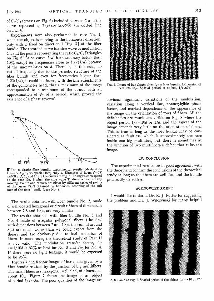
Figures 7 and 8 show images of bar charts given by afiber bundle realized by the junction of big multifibers.The small fibers are hexagonal, well clad, of dimensionsabout 10 . Figure 7 shows the image of an objectof period 1v1-3d. The poor qualities of the image are
FIG. 7. Image of bar charts given by a fiber bundle. Dimension offibers d-10 A. Spatial period of object, l/vfŽ-3d.
obvious: significant variations of the modulation,variation along a vertical line, nonnegligible phasefactor, and marked dependence of the appearance ofthe image on the orientation of rows of fibers. All thedeficiencies are much less visible on Fig. 8 where theobject period 1/v= 10d or 12d, and the aspect of theimage depends very little on the orientation of fibers.This is true as long as the fiber bundle may be con-sidered as faultless, which is approximately the caseinside one big multifiber, but there is sometimes atthe junction of two multifibers a defect that ruins theimage.
IV. CONCLUSION
The experimental results are in good agreement withthe theory and confirm the conclusions of the theoreticalstudy as long as the fibers are well clad and the bundlepractically defectless.
ACKNOWLEDGMENT
I would like to thank Dr. R. J. Potter for suggestingthe problem and Dr. J. Wilczynski for many helpful
FIG. 8. Same as Fig. 7. Spatial period of the object, l1/v20 or 12d.
913July 1964
RENEE DROUGARD
discussions. I am particularly grateful to Dr. H. H.Hopkins for a critical reading of the manuscript.
APPENDIX
Periodicities and Symmetries ofthe Fiber Structure
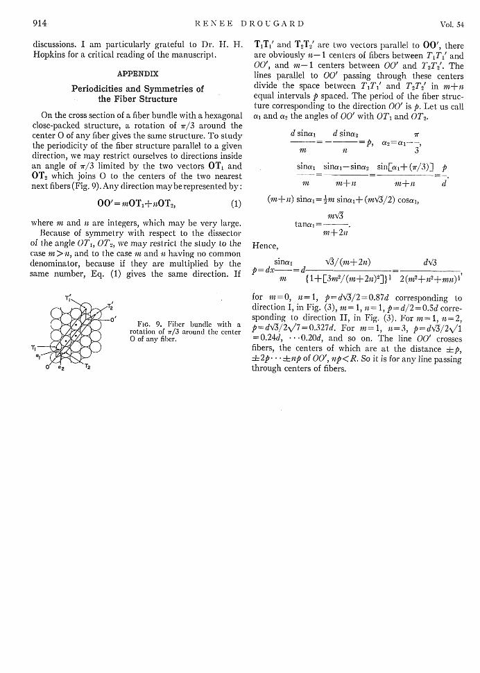
On the cross section of a fiber bundle with a hexagonalclose-packed structure, a rotation of 7r/3 around thecenter 0 of any fiber gives the same structure. To studythe periodicity of the fiber structure parallel to a givendirection, we may restrict ourselves to directions insidean angle of 7r/3 limited by the two vectors OT1 andOT2 which joins 0 to the centers of the two nearestnext fibers (Fig. 9). Any direction maybe represented by:
00'= iOT1+nOT2, (1)
where in and n are integers, which may be very large.Because of symmetry with respect to the dissector
of the angle OTI, OT2, we may restrict the study to thecase in > n, and to the case in and t having no commondenominator, because if they are multiplied by thesame number, Eq. (1) gives the same direction. If
FIG. 9. Fiber bundle with arotation of 7r/3 around the center0 of any fiber.
T1Ti' and T2T2' are two vectors parallel to 00', thereare obviously n- 1 centers of fibers between T1Ti' and00', and rn-I centers between 00' and T2T2'. Thelines parallel to 00' passing through these centersdivide the space between T1T1' and T 2T 2' in rn+-nequal intervals p spaced. The period of the fiber struc-ture corresponding to the direction 00' is p. Let us calla, and a2 the angles of 00' with OTh and OT2.
d sinai d sina2 X- =- P, a2=al----,
1r1 n 3
sinai sina1 -sina 2 sinai+ (7r/3)] p
in in+ ri mn+n d
(n+sn) sinai= 'in sinai+ (mV3/2) cosal,
tana =--.An+2n
Hence,
sina1 8/(in+2n) do-p=dx- =d - -
in {1+[3m2/(mn+2n)2]} l 2(r 2A n2±rn)2
for in=(, n= 1, p=d3/2=0.87d corresponding todirection I, in Fig. (3), in= 1, it= 1, p=d/2=O.Sd corre-sponding to direction II, in Fig. (3). For in= 1, n= 2,p=d//2V/7=0.327d. For fn=1, n=3, p=d'4322V'1= 0.24d, * O.20d, and so on. The line 00' crossesfibers, the centers of which are at the distance Lp,.2p .... **np of 00', np<R. So it is for any line passingthrough centers of fibers.