70
Optical Waveguides, Devices and Applications Wei-Chih Wang Southern Taiwan University of Technology

Optical Waveguides, Devices andApplications
Wei-Chih WangSouthern Taiwan University
of Technology
Class Information• Time: T/Th 10:00-12:00 change to M/T 10:00 to 12:00?• Instructor: Wei-Chih Wang
office: S606office hour: Mon and Tues
• Textbooks:- Guide-wave Optoeletronics, T. Tamir, ed., Springer Verlag- Optoelectronics and Photonics: Principles and Practices, S. O.
Kasap, Prentice Hall.- Integrated Optics: Theory and Technology, R. G. Hunsperger,Springer-Verlag
- Optical Fiber Communications, J. Senior, Prentice- Hall- Fundamentals of Photonics, B. Saleh, John Wiley& Sons- Fiber optic Sensors, E. Udd, John Wiley& Sons- Selected papers in optical sensors, optical MEMS devices and integrated
Optical devices.w. wang
Class information
• GradingHomework assignments 60%Final Project 40%
• Final Project:- Choose topics related to fiberopic sensors, waveguidesensors or integrated optics devices and optical MEMSsystem.- Details of the project will be announced in mid quarter- Two people can work as a team on a project, but eachperson needs to turn in his/her own final report.- Poster presentation will be held in the end of the quarteron your final project
w. wang

Course Outline
GOALS: To develop student understanding ofWeek 1 Theory of Waveguides : Ray-Optics ApproachWeek 2 Theory of Waveguides : Electromagnetic-Wave ApproachWeek 3 Theory of Waveguides : Modes in Rectangular Waveguides, Losses in
WaveguidesWeek 4 Theory of waveguides : Waveguide couplingWeek 5 Optical sources and detectorsWeek 6 Intensity modulation sensorsWeek 7 Interferometric sensorsWeek 8 Biosensor, bio-optics and biomedical ApplicationsWeek 9 Final project presentation
w. wang
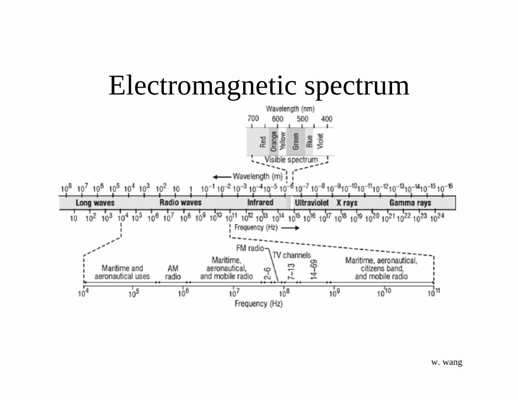
Electromagnetic spectrum
w. wang

Photonics is defined as the generation, manipulation, transport, detection, anduse of light information and energy whose quantum unit is the photon.
Photonics is based on the science of optics and electronics. The origins ofoptical technology (photonics) date back to the remote past. Exodus 38:8 (ca1200 BCE) tells of “the looking glasses of the women.” In the coming century,photonics promises to be a vital part of the information revolution.
To enable us to understand and apply photonics, it is necessary to have a basicunderstanding of the behavior and properties of light. This course focuses onthese fundamentals of photonics
w. wang
•Medicine-biomedical (laser surgery and in noninvasive diagnostic tools)•Environmental (measure the pollutants in air and water)•Energy (harness solar energy)•Transportation (, provides guidance, collision avoidance, and continuoustuning of engines based on driving conditions)•Defense (weapon guidance, remote sensing, image processing, and high-energy laser operation)•Computers and Communication and information technology (gathering,manipulating, storing, routing, and displaying information)•Manufacturing with photonics and test and analysis (industrial lasers thatcut, weld, trim, drill holes, and heat-treat products. inspection isperformed using spectroscopy, interferometry, machine vision, and imageprocessing)
Photonics Opportunities
w. wang

Optical MEMS and WaveguideIntegrated Optics
Photonic integrated circuit include optical MEMS andwaveguide integrated optics
Optical MEMS(can be free space or waveguide)
Waveguide Integrated Optics(what’s known as integrated optics in earlier day)
w. wang

Fiber optic and WaveguideSensors
Ocenan optics
Fiber optic Sensors waveguide based optoelectronicbio-sensor systems
Center for Bio-Optoelectronic SensorSystemsUniversity of Illinois ,
w. wang
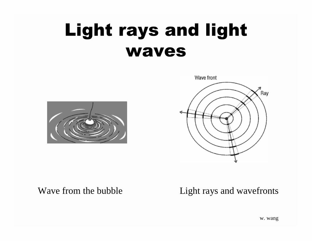
Light rays and light
waves
Light rays and wavefrontsWave from the bubble
w. wang
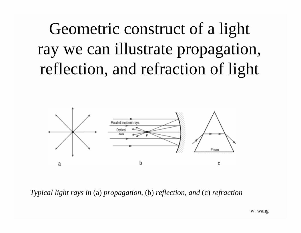
Typical light rays in (a) propagation, (b) reflection, and (c) refraction
Geometric construct of a lightray we can illustrate propagation,reflection, and refraction of light
w. wang

Light can be guided by planar or rectangular wave guides, or by optical fibers.
w. wang
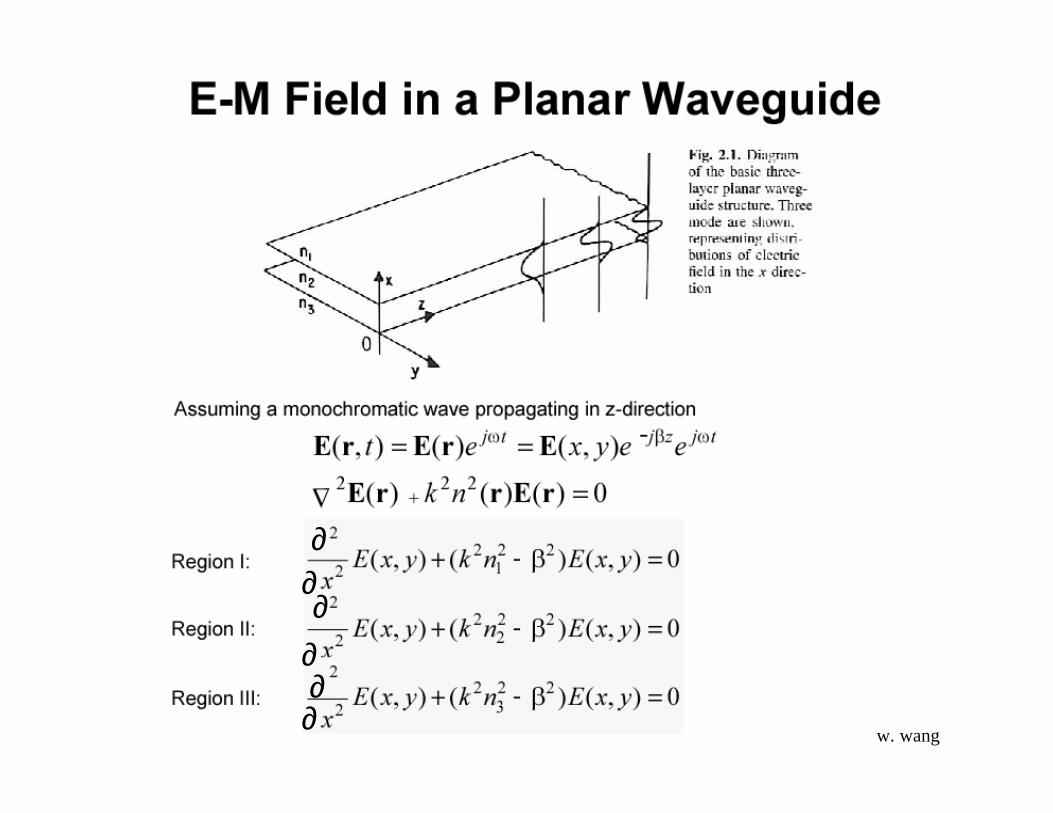
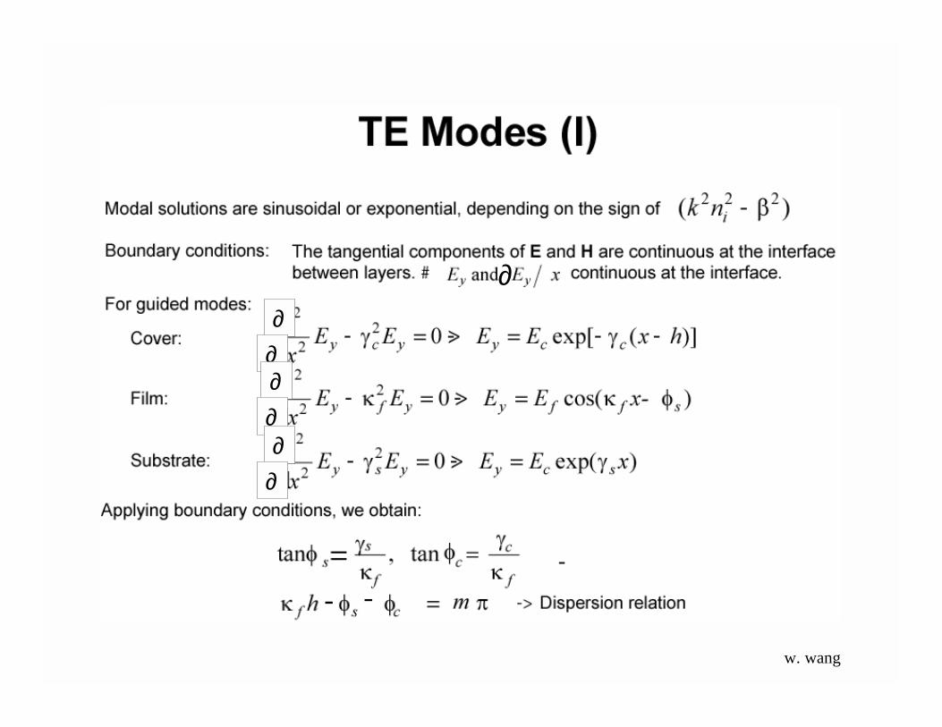
∂∂∂
∂∂∂
w. wang

w. wang
∂
w. wang
w. wang
w. wang

w. wang
w. wang
-
w. wang
w. wang
w. wang
w. wang
w. wang
w. wang
w. wang

=w. wang
w. wang
w. wang
∂∂∂∂∂∂
∂∂∂∂∂
∂
w. wang
∂∂
∂∂∂∂
∂
-
w. wang
w. wang
∂∂∂∂∂∂
w. wang

w. wang
w. wang

w. wang
w. wang
w. wang
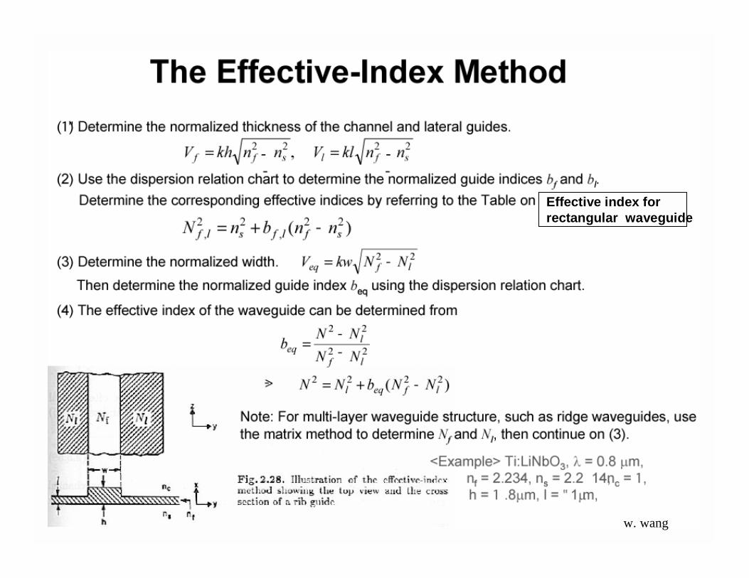
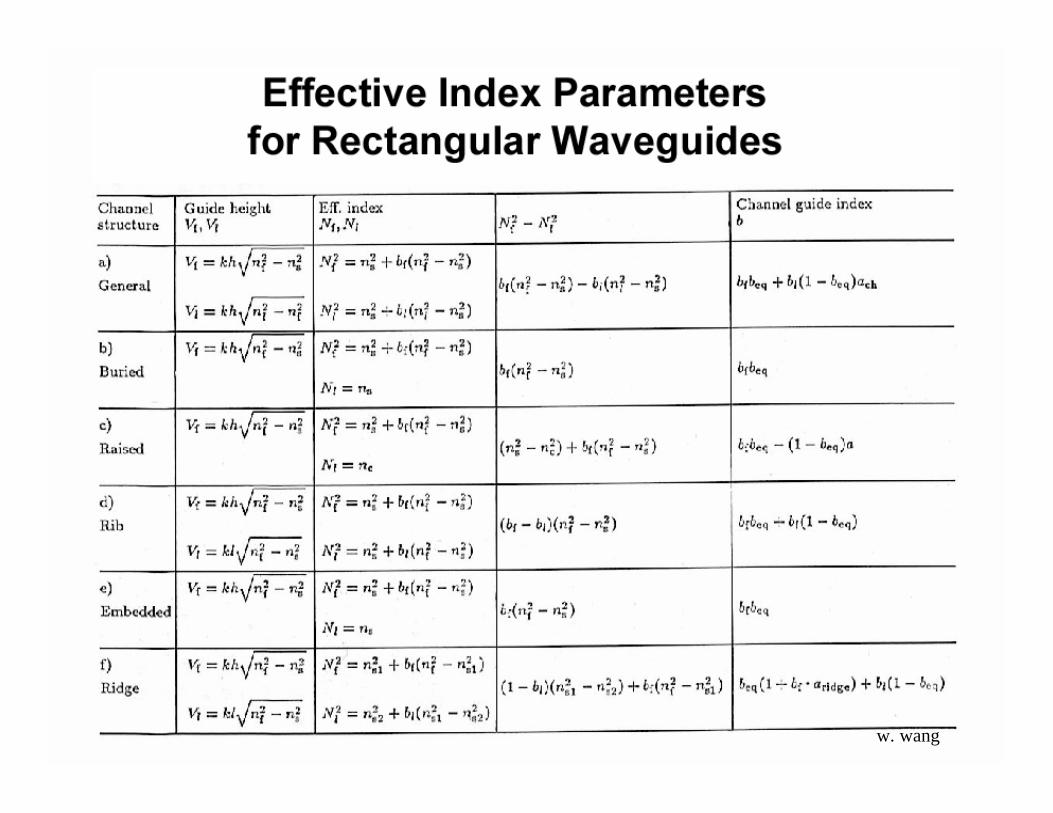
Effective index forrectangular waveguide
w. wang
--
w. wang
w. wang
w. wang
w. wang

Wave Analysis:
Cylindrical dielectric waveguide(step fiber)
assume all fields proportional to ej(ωt-βz)
E = (Er, Eφ, Ez )H = (Hr, Hφ,Hz )
Ei and Hi are function of (r, φ)
∇ 2 E = ω*µε ΕH H
But now need to use cylindrical coordinates:
d2Ez/dr2 + 1/r dEz/dr + 1/r2 d2Ez/dφ2 + (n12k2 – β2)Ez =0
w. wang

Assume Ez proportional to E(r) h(φ) separation of variables
Since h(2p + φ) = h(φ) =>try h(φ) = sin l φcos(l φ)ejlφ
where l= integersSubstitute back into
d2Ez/dr2 + 1/r dEz/dr + [(n12k2 – β2)-l2/r2]Ez =0 => Bessel function
Solutions closer to match physical situation.
w. wang

For guided solutions:
In core, solutions must be finiteIn cladding, solutions must approach 0 as r --> ∞
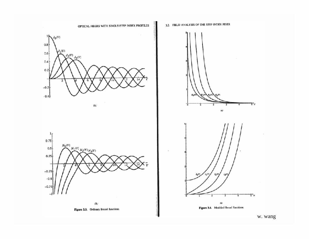
For r < a: E(r) ∝ Jl (UR) “ Bessel function of 1st kind”
For r > a: E(r) ∝ Kl (WR) “ modified Bessel function of 2nd kind”
UR = (n12k2 –β2)0.5 r = a(n1
2k2 –β2) 0.5 r/aU R
WR= (β2 - n12k2)0.5 a
Let V2 = U2 + W2 = a2 [n12k2 –β2 + β2 –n2
2k2] = a2k2[n12-n2
2]
∴ V = a · (2π/λ) [n12-n2
2] 0.5 (Normalized frequency)= a · (2π/λ) · ΝΑ
w. wang
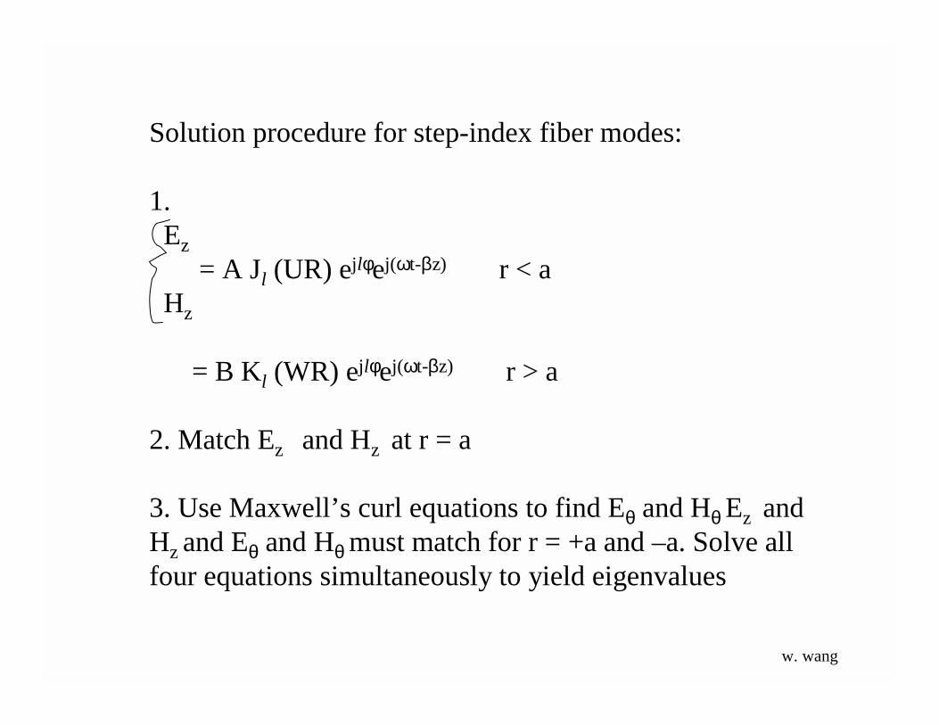
Solution procedure for step-index fiber modes:
1.Ez
= A Jl (UR) ejlφej(ωt-βz) r < aHz
= B Kl (WR) ejlφej(ωt-βz) r > a
2. Match Ez and Hz at r = a
3. Use Maxwell’s curl equations to find Eθ and Hθ Ez andHz and Eθ and Hθ must match for r = +a and –a. Solve allfour equations simultaneously to yield eigenvalues
w. wang
w. wang
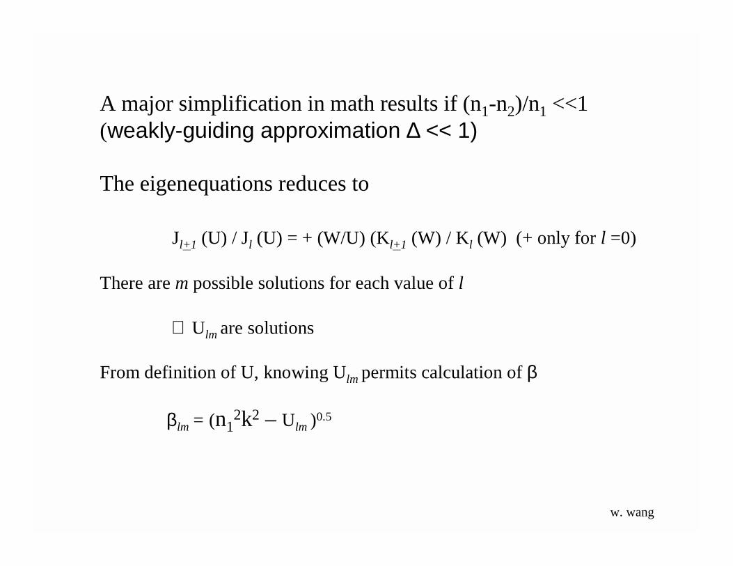
A major simplification in math results if (n1-n2)/n1 <<1(weakly-guiding approximation ∆ << 1)
The eigenequations reduces to
Jl+1 (U) / Jl (U) = + (W/U) (Kl+1 (W) / Kl (W) (+ only for l =0)
There are m possible solutions for each value of l
∴ Ulm are solutions
From definition of U, knowing Ulm permits calculation of β
βlm = (n12k2 – Ulm )0.5
w. wang

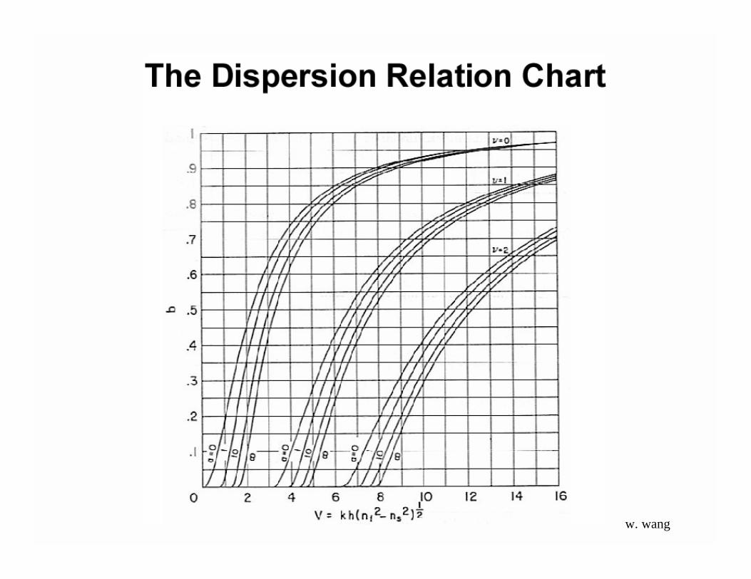
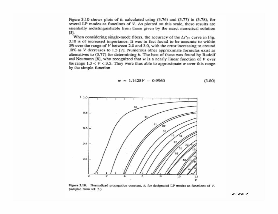
The resulting system of equations can only be solved graphically. Thegraphical solutions represent the mode cutoffs for the different modes thatcan propagate in the fiber for any given V, where V is a convenientparameter determined by the properties of the fiber and wavelength ofincident light.
V = 2*π/λ*a*NA
The intersections representthe V numbers at whichthese two modes turn on inthe fiber.
w. wang

w. wang

The normalized wave number, or V-number of a fiber is defined as V = kf aNA. Here kf, is the free space wave number, 2π/λ0, a is the radius of the core, andNA is the numerical aperture of the fiber, NA = (ncore
2 - ncladding2)1/2 ≈ ncore(2∆)1/2,
with ∆ = (ncore-ncladding)/ncore. Many fiber parameters can be expressed in terms ofV. The TE and TM modes have non-vanishing cut-off frequencies. The cutofffrequency is found from V = aω(2∆)½/c = 2.405. Only the lowest HE mode, HE11,has no cutoff frequency. For 0 < V < 2.405 it is the only mode that propagates inthe fiber. w. wang
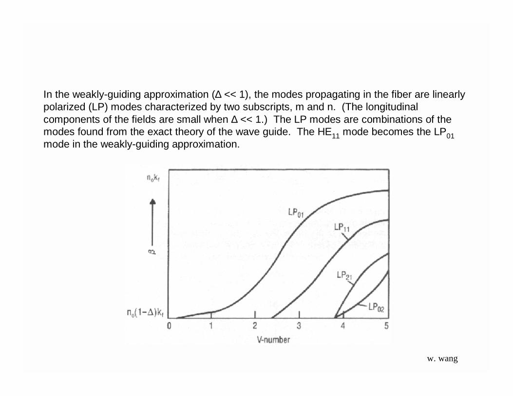
In the weakly-guiding approximation (∆ << 1), the modes propagating in the fiber are linearlypolarized (LP) modes characterized by two subscripts, m and n. (The longitudinalcomponents of the fields are small when ∆ << 1.) The LP modes are combinations of themodes found from the exact theory of the wave guide. The HE11 mode becomes the LP01mode in the weakly-guiding approximation.
w. wang
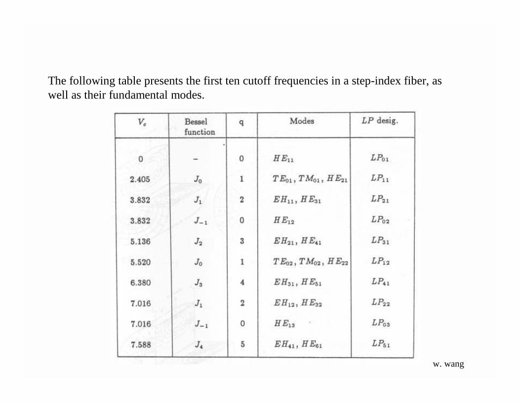
The following table presents the first ten cutoff frequencies in a step-index fiber, aswell as their fundamental modes.
w. wang

Single mode (SM) fiber is designed such that all the higher orderwaveguide modes are cut-off by a proper choice of thewaveguide parameters as given below.
where, λ is the wavelength, a is the core radius, and n1 and n2 arethe core and cladding refractive indices, respectively. When V <2.405 single mode condition is ensured. SM fiber is an essentialrequirement for interferometric sensors. Due to the small core size(~4 µ m) alignment becomes a critical factor.
Single mode fiber
w. wang
w. wang

Electric and magnetic fields for eight fundamental modes.
w. wang

When the V number is less than 2.405 only the LP01mode propagates. When the V number is greater than2.405 the next linearly-polarized mode can besupported by the fiber, so that both the LP01 and LP11,modes will propagate.
LP01 LP11
w. wang

w. wang

The SM fiber mentioned above is not truly single mode in that twomodes with degenerate polarization states can propagate in the fiber.This can lead to signal interference and noise in the measurement.The degeneracy can be removed and a single mode polarizationpreserving fiber can be obtained by the use of an elliptical core fiberof very small size or with built in stress. In either case light launchedalong the major axis of the fiber is preserved in its state ofpolarization. It is also possible to make a polarizing fiber in whichonly one state of polarization is propagated. Polarimetric sensorsmake use of polarization preserving fibers. Thus, multimode fiber,single mode fiber and polarization preserving fiber are the threeclasses of fibers which are used in the intensity type, theinterferometric type and the polarimetric type of sensors,respectively.
w. wang

While discussing step-index fibers, we considered light propagation inside the fiber as aset of many rays bouncing back and forth at the core-cladding interface. There the angle θcould take a continuum of values lying between 0 and cos–1(n2/n1), i.e.,
Scientific and Technological Education in Photonics
0 < θ < cos–1 (n2/n1)
For n2 = 1.5 and ∆ ≈ = 0.01, we would get n2/n 1~ and cos –1 = 8.1°, so
0 < θ < 8.1°
w. wang

Now, when the core radius (or the quantity ∆) becomes very small, ray optics does not remainvalid and one has to use the more accurate wave theory based on Maxwell's equations.
In wave theory, one introduces the parameter
where ∆ has been defined earlier and n1~ n2 . The quantity V is often referred to as the "V-
number" or the "waveguide parameter" of the fiber. It can be shown that, if
V < 2.4045
only one guided mode (as if there is only one discrete value of θ) is possible and the fiber is knownas a single-mode fiber. Further, for a step-index single-mode fiber, the corresponding (discrete)value of θ is approximately given by the following empirical formula
We may mention here that because of practical considerations the value ∆ of ranges from about0.002 to about 0.008
w. wang
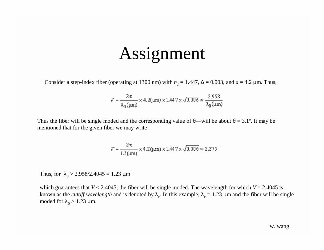
Consider a step-index fiber (operating at 1300 nm) with n2 = 1.447, ∆ = 0.003, and a = 4.2 µm. Thus,
Thus the fiber will be single moded and the corresponding value of θ—will be about θ = 3.1º. It may bementioned that for the given fiber we may write
Thus, for λ0 > 2.958/2.4045 = 1.23 µm
which guarantees that V < 2.4045, the fiber will be single moded. The wavelength for which V = 2.4045 isknown as the cutoff wavelength and is denoted by λc. In this example, λc = 1.23 µm and the fiber will be singlemoded for λ0 > 1.23 µm.
Assignment
w. wang
Assignment
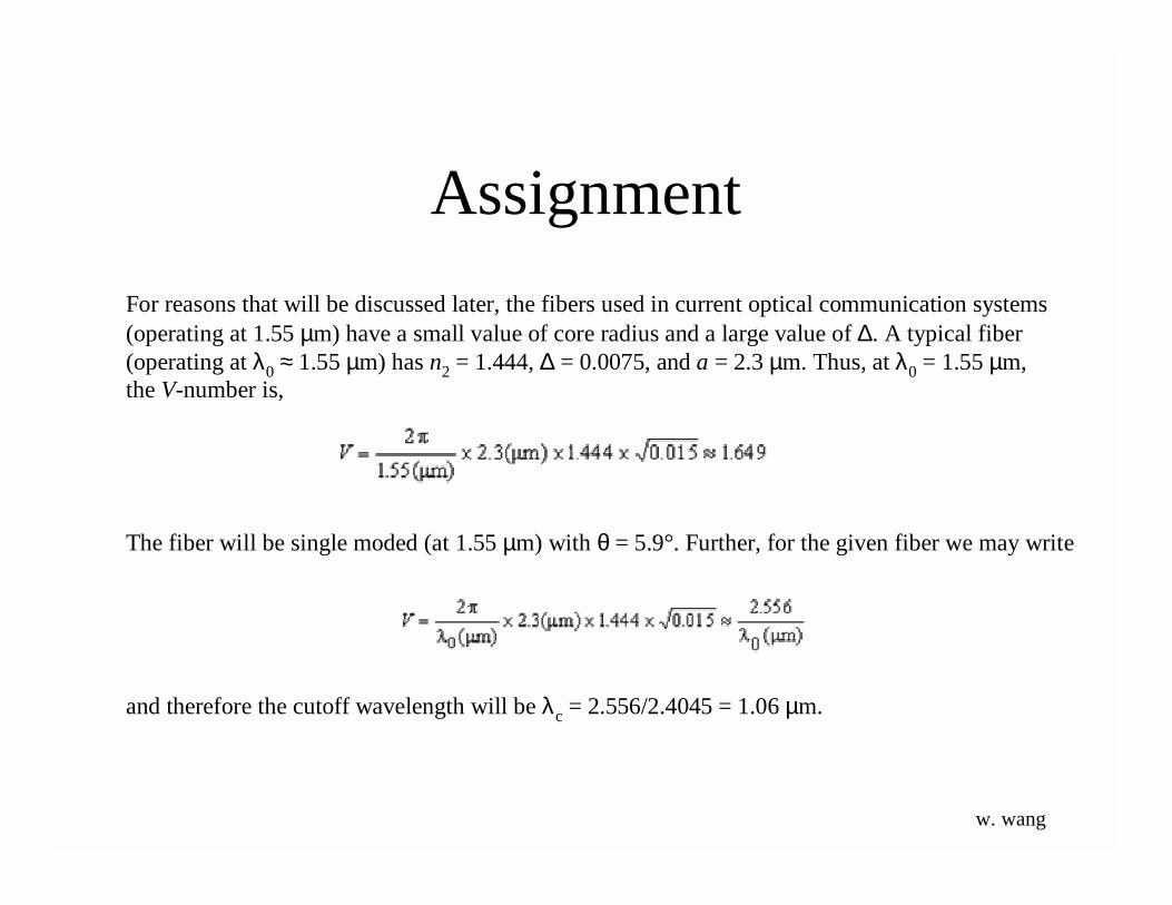
For reasons that will be discussed later, the fibers used in current optical communication systems(operating at 1.55 µm) have a small value of core radius and a large value of ∆. A typical fiber(operating at λ0 ≈ 1.55 µm) has n2 = 1.444, ∆ = 0.0075, and a = 2.3 µm. Thus, at λ0 = 1.55 µm,the V-number is,
The fiber will be single moded (at 1.55 µm) with θ = 5.9°. Further, for the given fiber we may write
and therefore the cutoff wavelength will be λc = 2.556/2.4045 = 1.06 µm.
w. wang
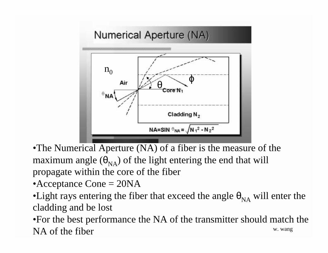
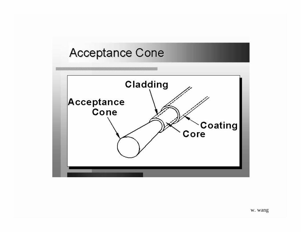
•The Numerical Aperture (NA) of a fiber is the measure of themaximum angle (θNA) of the light entering the end that willpropagate within the core of the fiber•Acceptance Cone = 20NA•Light rays entering the fiber that exceed the angle θNA will enter thecladding and be lost•For the best performance the NA of the transmitter should match theNA of the fiber
n0
θ ϕ
w. wang
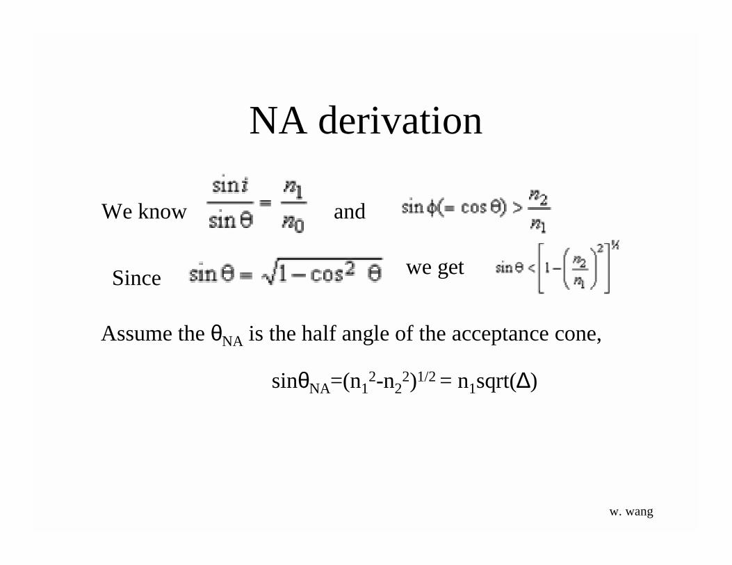
NA derivation
We know and
Since
Assume the θNA is the half angle of the acceptance cone,
we get
sinθNA=(n12-n2
2)1/2 = n1sqrt(∆)
w. wang
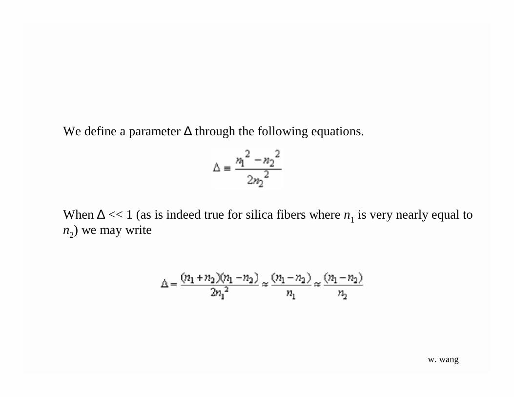
We define a parameter ∆ through the following equations.
When ∆ << 1 (as is indeed true for silica fibers where n1 is very nearly equal ton2) we may write
w. wang
w. wang
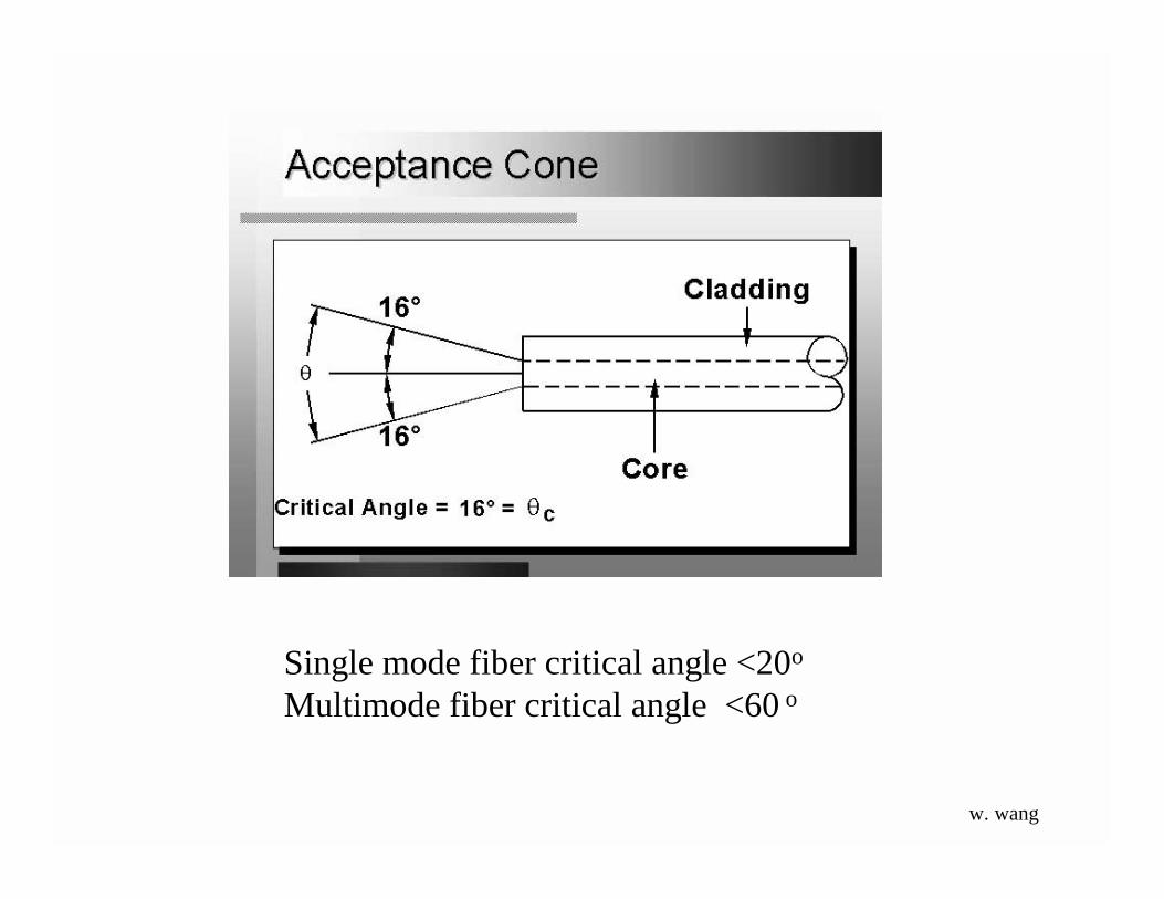
Single mode fiber critical angle <20o
Multimode fiber critical angle <60 o
w. wang

In a short length of an optical fiber, if all rays between i = 0 and im are launched, thelight coming out of the fiber will also appear as a cone of half-angle im emanating fromthe fiber end. If we now allow this beam to fall normally on a white paper and measureits diameter, we can easily calculate the NA of the fiber.
For a typical step-index (multimode) fiber with n1 ≈ 1.45 and ∆ ≈ 0.01, we get
so that im ≈ 12°. Thus, all light entering the fiber must be within a cone ofhalf-angle 12°.
Example
w. wang


