Page 1
7/21/2019 Optimal Based Damping Controllers of Unified Power Flow Controller Using Adaptive Tabu Search
http://slidepdf.com/reader/full/optimal-based-damping-controllers-of-unified-power-flow-controller-using-adaptive 1/6
Abstract —This paper presents optimal based damping controllers
of Unified Power Flow Controller (UPFC) for improving the
damping power system oscillations. The design problem of UPFC
damping controller and system configurations is formulated as an
optimization with time domain-based objective function by means of
Adaptive Tabu Search (ATS) technique. The UPFC is installed in
Single Machine Infinite Bus (SMIB) for the performance analysis of
the power system and simulated using MATLAB’s simulink. The
simulation results of these studies showed that designed controller
has an tremendous capability in damping power system oscillations.
Keywords —Adaptive Tabu Search (ATS), damping controller,
Single Machine Infinite Bus (SMIB), Unified Power Flow Controller
(UPFC).
I. I NTRODUCTION
OWER systems are today much more loaded than before
due to growing rapidly in power demand including
expansion in transmission and generation is restricted. This
causes the power systems to be operated next to their stabilitylimits, power system oscillation and finally power system
instabilities.
Recently development of power electronics devices
introduces the use of systems Flexible AC Transmission
System (FACTS) controllers in power system. FACTS devices
have been effective in controlling power flow and damping
power system oscillations [1]. UPFC is one of the most
complex FACTS devices in a power system. It is primarily
used for independent control of real and reactive power in
transmission lines [2], [3]. UPFC could be applied for
improvement by damping of power system oscillations [4],
[5].
In the previous research have presented lead-lag controllertype and output feedback controller type UPFC damping
controllers [6], [7], [8]. They are designed for a specific
operating condition using linear models of modified Heffron-
Phillips transfer function model [9], [10]. The advanced
control schemes such as Particle Swarm Optimization and
R. Taithai is with the Center of Excellence in Electric Energy, Smart
Materials, and Health Science. School of Electrical Engineering, Institute of
Engineering, Suranaree University of Technology, Nakhon Ratchasima,
Thailand (e-mail: [email protected] ).A. Oonsivilai, corresponding author, is with the Center of Excellence in
Electric Energy, Smart Materials, and Health Science, Postharvest
Technology Research Center. School of Electrical Engineering, Institute of
Engineering, Suranaree University of Technology, Nakhon Ratchasima,30000 Thailand (e-mail: [email protected] ).
Genetic algorithms [11], Chaotic Optimization [12] and
Shuffled Frog Leaping Algorithm [13] offer better dynamic
performances than fixed parameter controllers.
The based damping controllers of UPFC parameter were
formulated as an optimization problem. By minimizing the
objective function in which the influences of speed deviation
are considered.
The main objective of this paper is to investigate the abilityof optimization methods was ATS algorithm [14] for UPFC
supplementary based damping controller design. This
algorithm optimizes the total system performance by means of
ATS algorithm. A modified linear Heffron-Phillips model of
SMIB power system installed with UPFC is considered as case
study and a UPFC based damping controller whose parameters
are optimized using ATS algorithm is considered as power
system oscillations. Simulation results show the validity of
proposed methods in damping of power system oscillations.
II. DESCRIPTION OF THE CASE STUDY
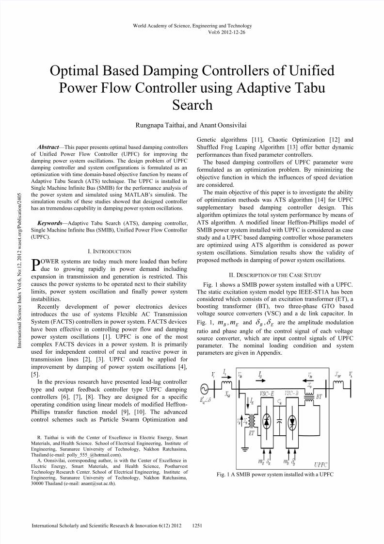
Fig. 1 shows a SMIB power system installed with a UPFC.The static excitation system model type IEEE-ST1A has been
considered which consists of an excitation transformer (ET), a
boosting transformer (BT), two three-phase GTO based
voltage source converters (VSC) and a dc link capacitor. In
Fig. 1, Bm , E m and Bδ , E δ are the amplitude modulation
ratio and phase angle of the control signal of each voltage
source converter, which are input control signals of UPFC
parameter. The nominal loading condition and system
parameters are given in Appendix.
Fig. 1 A SMIB power system installed with a UPFC
Optimal Based Damping Controllers of Unified
Power Flow Controller using Adaptive Tabu
Search
Rungnapa Taithai, and Anant Oonsivilai
P
World Academy of Science, Engineering and Technology
Vol:6 2012-12-26
1251International Scholarly and Scientific Research & Innovation 6(12) 2012
I n t e r n a t i o n a l S c i e n c e I n d e x V o
l : 6 , N o : 1 2 , 2 0 1 2 w a s e t . o r g / P u b l i c a t i o n / 2 4 0 5
Page 2
7/21/2019 Optimal Based Damping Controllers of Unified Power Flow Controller Using Adaptive Tabu Search
http://slidepdf.com/reader/full/optimal-based-damping-controllers-of-unified-power-flow-controller-using-adaptive 2/6
A. Power System Nonlinear Model with UPFC
The dynamic model of UPFC is required in order to the
UPFC effect study for enhancing small signal stability of
power system. Park’s transformation is applied and neglecting
the resistance and transients of the ET and BT transformers,
UPFC can be modeled as:
+
−=
2
sin2
cos
0
0
E dc E
E dc E
Eq
Ed
E
E
Eq
Ed
V m
V m
i
i
x
x
v
v
δ
δ
(1)
+
−=
2
sin2
cos
0
0
Bdc B
Bdc B
Bq
Bd
B
B
Bq
Bd
V m
V m
i
i
x
x
v
v
δ
δ
(2)
[ ]
[ ]
+
=
Bq
Bd
B B
dc
B
Eq
Ed
E E
dc
E dc
i
i
C
m
i
i
C
mv
δ δ
δ δ
sincos4
3
sincos4
3&
(3)
where, E v , E i , Bv and Bi are excitation voltage, excitation
current, boosting voltage, and boosting current, respectively;
dcC and dcv are dc link capacitance and voltage. The
nonlinear model of SMIB power system shown in Fig. 1 is
described by:
ω ω δ ∆=•
0 (4)
( ) M D P P em ω ω ∆−−=•
(5)
( ) '
0
'
d fd qq T E E E +−=•
(6)
( )t t
a
a fd
a
fd V V T
K E
T E −+−=
•
0
1 (7)
where
td td tqtqe iviv P += (8)
td d d qq i X X E E '' −+= (9)
td d qtq i X E v '' −= (10)
tqqtd i X v = (11)
( )22
tqtd t vvV += (12)
Bd Ed td iii += (13)
Bq Eqtq iii += (14)
B. Power System Linearized Model with UPFC
A linear dynamic model is obtained by linearizing the
nonlinear model round an operating condition. The linearized
model of power system shown in Fig. 1 is given as in the
following:
ω ω δ ∆=∆ •
0 (15)
( ) M D P P em ω ω ∆−∆−∆=∆•
(16)
( ) '
0
'
d fd qq T E E E ∆+∆−=∆•
(17)
t
a
a fd
a
fd V T
K E
T E ∆+∆−=∆ • 1
(18)
B p B pb E p E pe
dc pd qe
be K m K K m K
V K E K K P
δ δ
δ
δ δ ∆+∆+∆+∆+
∆+∆+∆=∆ '
21(19)
Bq Bqb E q E qe
dcqd qq
be K m K K m K
V K E K K E
δ δ
δ
δ δ ∆+∆+∆+∆+
∆+∆+∆=∆ '
34
'
(20)
Bv Bvb E v E ve
dcvd qt
be K m K K m K
V K E K K V
δ δ
δ
δ δ ∆+∆+∆+∆+
∆+∆+∆=∆ '
65 (21)
Bc Bcb E c E ce
dcqdc
be K m K K m K
V K E K K V
δ δ
δ
δ δ ∆+∆+∆+∆+
∆−∆+∆=∆ •
9
'
87 (22)
where, 921 ,...,, K K K , pu K , qu K , vu K and cu K are
linearization constants [5]. The state-space model of power
system is given by:
Bu Ax x +=•
(23)
where, the state vector , control vector u , A and B are:
[ ]T
dc fd q V E E x ∆∆∆∆∆= 'ω δ
[ ]T
B B E E mmu δ δ ∆∆∆∆=
−
−−−−
−−−
−−−−
=
987
65
'
0
''
0
3
'
0
4
21
0
00
10
10
0
0000
K K K
T
K K
T T
K K
T
K K
T
K
T T
K
T
K M
K
M
K
M
D
M
K
A
a
vd a
aa
a
a
a
d
qd
dod d
pd
ω
World Academy of Science, Engineering and Technology
Vol:6 2012-12-26
1252International Scholarly and Scientific Research & Innovation 6(12) 2012
I n t e r n a t i o n a l S c i e n c e I n d e x V o
l : 6 , N o : 1 2 , 2 0 1 2 w a s e t . o r g / P u b l i c a t i o n / 2 4 0 5
Page 3
7/21/2019 Optimal Based Damping Controllers of Unified Power Flow Controller Using Adaptive Tabu Search
http://slidepdf.com/reader/full/optimal-based-damping-controllers-of-unified-power-flow-controller-using-adaptive 3/6
−−−−
−−−−
−−−−
=
be
be
be
be
ccbcce
a
va
a
vba
a
va
a
vea
d
q
d
qb
d
q
d
qe
p pb p pe
K K K K
T
K K
T
K K
T
K K
T
K K
T
K
T
K
T
K
T
K M
K
M
K
M
K
M
K
B
δ δ
δ δ
δ δ
δ δ
'0
'0
'0
'0
0000
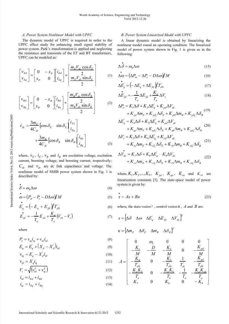
In Fig. 2 shows the block diagram of the linearized dynamic
model of SMIB power system installed with UPFC.
∑ ∑
∑
∑∑
s0
ω
1 K
2 K
6 K
4 K 5
K
8 K
7 K
ω ∆
DMs+
1 δ ∆
m P ∆
'
q E ∆ '
03
1
d sT K +
fd E ∆
A
A
sT
K
+1
ref V ∆
9
1
K s+[ ]u∆
dcV ∆
pu K qu K [ ]vu K
[ ]cu K
qd K vd K pd K
+
e P ∆+
+
+ +
−
+
+
−−
− −−
− −
+
+
+
UPFC
Fig. 2 Modified Heffron-Phillips transfer function model
III. DAMPING CONTROLLER OF UPFC
The damping controllers are designed to produce an
electrical torque in phase with speed deviation. The four
control signal parameters of the UPFC ( Bm , E m , Bδ and E δ )
could be modulated in order to produce the damping torque.The speed deviation ( ω ∆ ) is considered as the damping
controllers input. In this paper shows two control signal
parameters, Bm and E δ , alternative are modulated and phase
angle of UPFC based damping controllers in order to
coordinated design.
The conventional approach is achieved by lead-lag
compensator employment as shown in Fig. 3. The block
consists of three blocks namely gain block, washout block and
lead-lag compensator. The time constants are varied
periodically to effect damping of oscillation. The change in
speed deviation is fed as input and the output is fed to the
UPFC parameters for stability improvement.
The block represents the lead-lag compensation where the
output parameter is the controller parameter selected to
achieve damping in UPFC.
dc K
W
W
sT sT +1
2
1
11
sT sT
++ω ∆ u∆
Fig. 3 Simplified UPFC damping controller block diagram
Where, dc K is the controller gain, 1T and 2T are the time
constants of compensation, wT is the time constant of
washout. The value of wT is not critical and may be in the
ranges of 1 to 20 seconds. The wT equal to 10 seconds is
chosen in the present studies [13].
IV. OBJECTIVE FUNCTION
Selecting optimal values for UPFC controller parameters of
a closed loop system is usually an iterative process and called
parameter tuning. The ATS algorithm was applied to improve
optimization synthesis and find the global optimum value of
fitness function. In this work, an Integral of Time multiplied
Absolute value of the Error (ITAE) is taken as the objective
function. Since the operating conditions in power systems are
often varied, a performance index for a wide range of
operating points is defined as follows:
( )dt t J simt
∫ ∆=0
ω (24)
where, ( )t ω ∆ is the speed deviation and simt is time range of
simulation.It is designed to minimize this objective function
for improving system response in terms of the settling time
and overshoots. The design problem could be formulated as
the following constrained optimization problem, where the
constraints are the controller parameters bounds:
max
22
min
2
max
11
min
1
maxmin
:
T T T
T T T K K K
to subject J Minimize
dcdcdc
≤≤
≤≤≤≤
Typical ranges of the optimized parameters are [0.01-100]
for K and [0.01-1] for 1T and 2T [12]. The UPFC controller
parameters optimization is carried out by evaluating the cost
function as given in equation (24).
V. ADAPTIVE TABU SEARCH ALGORITHM
ATS technique is the extended version of the Tabu search(TS) algorithm by adding both concepts that is back tracking
World Academy of Science, Engineering and Technology
Vol:6 2012-12-26
1253International Scholarly and Scientific Research & Innovation 6(12) 2012
I n t e r n a t i o n a l S c i e n c e I n d e x V o
l : 6 , N o : 1 2 , 2 0 1 2 w a s e t . o r g / P u b l i c a t i o n / 2 4 0 5
Page 4
7/21/2019 Optimal Based Damping Controllers of Unified Power Flow Controller Using Adaptive Tabu Search
http://slidepdf.com/reader/full/optimal-based-damping-controllers-of-unified-power-flow-controller-using-adaptive 4/6
and adaptive radius. These both concepts could improve the
TS method performance. The TS technique normally provides
local solution when the problem is complicated having many
local points. Hence, the back tracking part and adaptive radius
added to TS algorithm (called ATS) could escape local lock
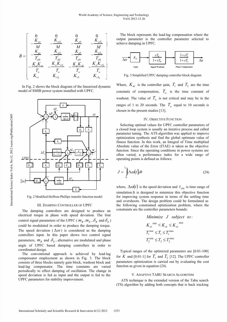
providing global solution. The more ATS details could befound in [14]. The diagram of ATS for optimization based
damping controller of UPFC parameters is shown in Fig. 4
[15].
Fig. 4 Flow chart for the ATS process
VI. SIMULATION R ESULTS
In this section, the SMIB power system installed with
UPFC was investigated. The simulation has been carried out
with Modified Heffron- Phillips transfer function model in
MATLAB’s simulink. The simulation result of the Modified
Heffron- Phillips transfer function model with four different
input control signals under nominal loading conditions in
mechanical power input is measured for analysis. Here, usingtwo of input control signals are Include Bm and E δ which is
controlled by base damping controllers of UPFC parameters
obtained from ATS algorithm.
Now, in order to damp the oscillations of power system will
be equipped with input control signals of damping controller
using ATS algorithms.
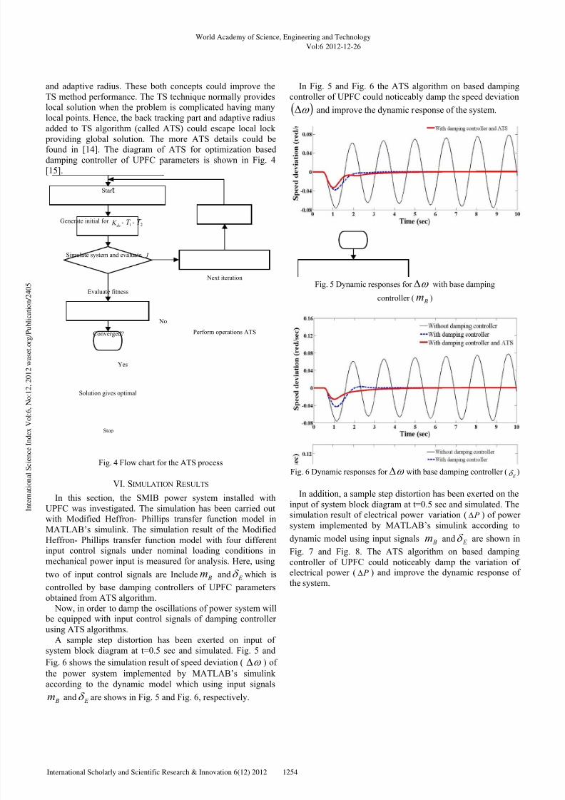
A sample step distortion has been exerted on input of
system block diagram at t=0.5 sec and simulated. Fig. 5 and
Fig. 6 shows the simulation result of speed deviation ( ω ∆ ) of
the power system implemented by MATLAB’s simulink
according to the dynamic model which using input signals
Bm and E δ
are shows in Fig. 5 and Fig. 6, respectively.
In Fig. 5 and Fig. 6 the ATS algorithm on based damping
controller of UPFC could noticeably damp the speed deviation
( )ω ∆ and improve the dynamic response of the system.
Fig. 5 Dynamic responses for ω ∆ with base damping
controller ( Bm )
Fig. 6 Dynamic responses for ω ∆ with base damping controller ( E δ )
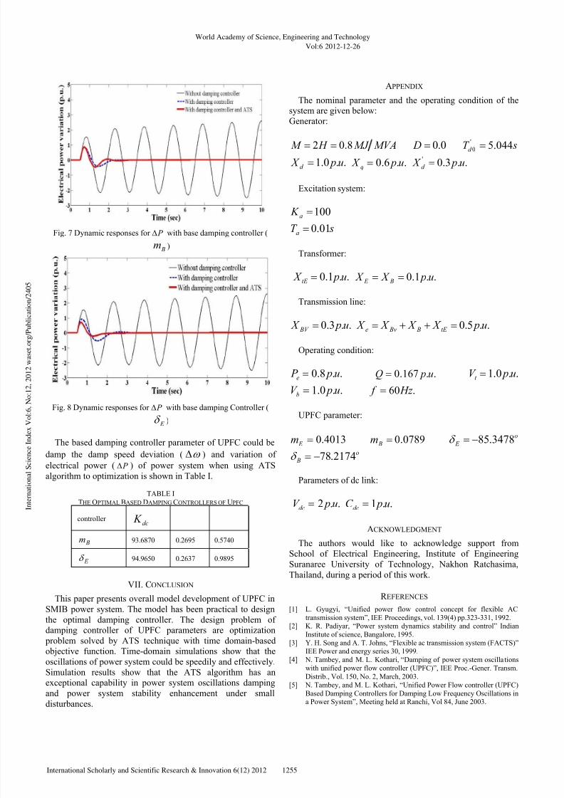
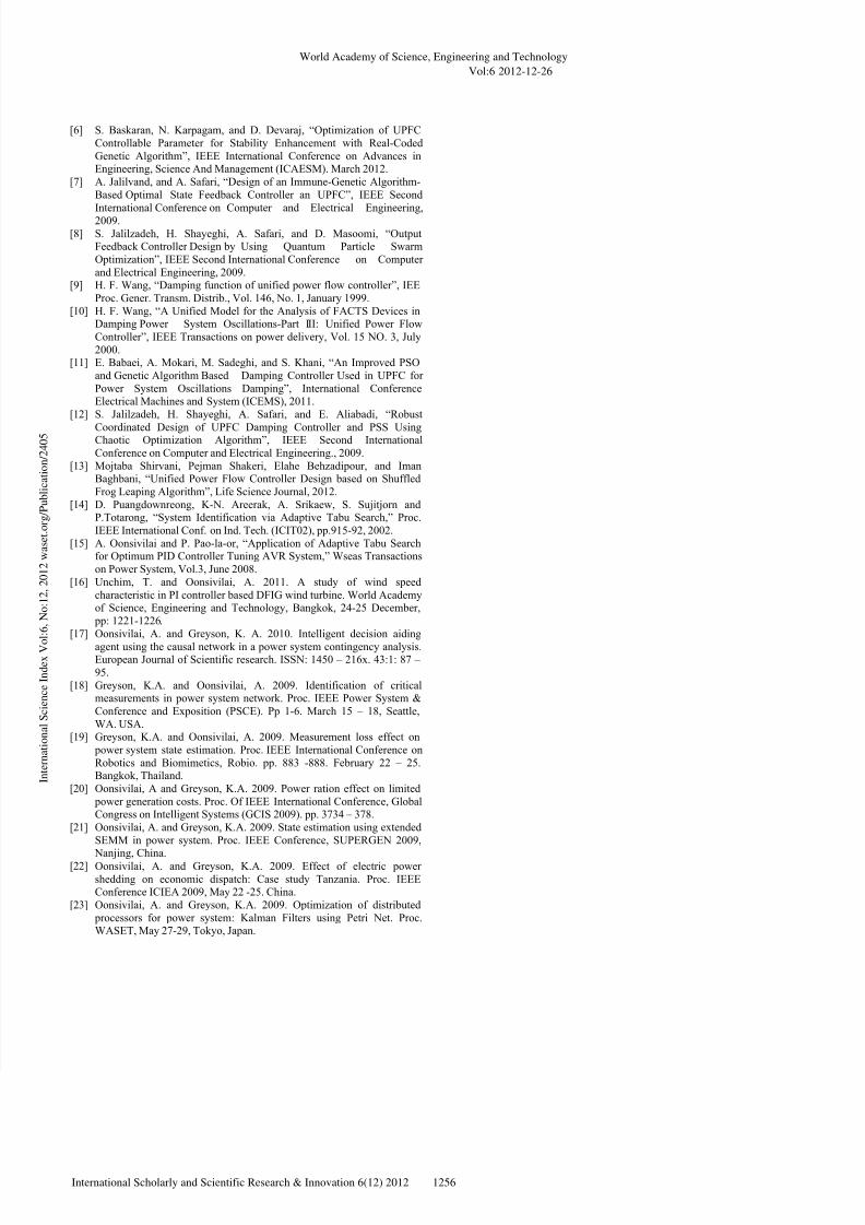
In addition, a sample step distortion has been exerted on the
input of system block diagram at t=0.5 sec and simulated. The
simulation result of electrical power variation ( P ∆ ) of power
system implemented by MATLAB’s simulink according to
dynamic model using input signals Bm and E δ are shown in
Fig. 7 and Fig. 8. The ATS algorithm on based damping
controller of UPFC could noticeably damp the variation ofelectrical power ( P ∆ ) and improve the dynamic response of
the system.
Star
Generate initial fordc K ,
1T ,2T
Simulate system and evaluate J
Converged?
Stop
Evaluate fitness
Perform operations ATS
Next iteration
Solution gives optimal
Yes
No
World Academy of Science, Engineering and Technology
Vol:6 2012-12-26
1254International Scholarly and Scientific Research & Innovation 6(12) 2012
I n t e r n a t i o n a l S c i e n c e I n d e x V o
l : 6 , N o : 1 2 , 2 0 1 2 w a s e t . o r g / P u b l i c a t i o n / 2 4 0 5
Page 5
7/21/2019 Optimal Based Damping Controllers of Unified Power Flow Controller Using Adaptive Tabu Search
http://slidepdf.com/reader/full/optimal-based-damping-controllers-of-unified-power-flow-controller-using-adaptive 5/6
Fig. 7 Dynamic responses for P ∆ with base damping controller (
Bm )
Fig. 8 Dynamic responses for P ∆ with base damping Controller (
E δ )
The based damping controller parameter of UPFC could be
damp the damp speed deviation ( ω ∆ ) and variation of
electrical power ( P ∆ ) of power system when using ATS
algorithm to optimization is shown in Table I.
TABLE I
THE OPTIMAL BASED DAMPING CONTROLLERS OF UPFC
controllerdc K
Bm 93.6870 0.2695 0.5740
E δ
94.9650 0.2637 0.9895
VII. CONCLUSION
This paper presents overall model development of UPFC in
SMIB power system. The model has been practical to design
the optimal damping controller. The design problem of
damping controller of UPFC parameters are optimization
problem solved by ATS technique with time domain-based
objective function. Time-domain simulations show that the
oscillations of power system could be speedily and effectively.
Simulation results show that the ATS algorithm has an
exceptional capability in power system oscillations damping
and power system stability enhancement under small
disturbances.
APPENDIX
The nominal parameter and the operating condition of the
system are given below:
Generator:
MVAMJ H M 8.02 == 0.0= D sT d 044.5'0 =
..0.1 u p X d = ..6.0 u p X q = ..3.0' u p X d =
Excitation system:
100=a K
sT a 01.0=
Transformer:
..1.0 u p X tE = ..1.0 u p X X B E ==
Transmission line:
..3.0 u p X BV = ..5.0 u p X X X X tE B Bve =++=
Operating condition:
..8.0 u p P e = ..167.0 u pQ = ..0.1 u pV t =
..0.1 u pV b = .60 Hz f =
UPFC parameter:
4013.0= E m 0789.0= Bm o
E 3478.85−=δ
o
B 2174.78−=δ
Parameters of dc link:
..2 u pV dc = ..1 u pC dc =
ACKNOWLEDGMENT
The authors would like to acknowledge support from
School of Electrical Engineering, Institute of Engineering
Suranaree University of Technology, Nakhon Ratchasima,
Thailand, during a period of this work.
R EFERENCES
[1]
L. Gyugyi, “Unified power flow control concept for flexible AC
transmission system”, IEE Proceedings, vol. 139(4) pp.323-331, 1992. [2]
K. R. Padiyar, “Power system dynamics stability and control” Indian
Institute of science, Bangalore, 1995. [3]
Y. H. Song and A. T. Johns, “Flexible ac transmission system (FACTS)”IEE Power and energy series 30, 1999.
[4]
N. Tambey, and M. L. Kothari, “Damping of power system oscilla tions
with unified power flow controller (UPFC)”, IEE Proc.-Gener. Transm.
Distrib., Vol. 150, No. 2, March, 2003. [5]
N. Tambey, and M. L. Kothari, “Unified Power Flow controller (UPFC)
Based Damping Controllers for Damping Low Frequency Oscillations in
a Power System”, Meeting held at Ranchi, Vol 84, June 2003.
World Academy of Science, Engineering and Technology
Vol:6 2012-12-26
1255International Scholarly and Scientific Research & Innovation 6(12) 2012
I n t e r n a t i o n a l S c i e n c e I n d e x V o
l : 6 , N o : 1 2 , 2 0 1 2 w a s e t . o r g / P u b l i c a t i o n / 2 4 0 5
Page 6
7/21/2019 Optimal Based Damping Controllers of Unified Power Flow Controller Using Adaptive Tabu Search
http://slidepdf.com/reader/full/optimal-based-damping-controllers-of-unified-power-flow-controller-using-adaptive 6/6
[6]
S. Baskaran, N. Karpagam, and D. Devaraj, “Optimization of UPFC
Controllable Parameter for Stability Enhancement with Real-Coded
Genetic Algorithm”, IEEE International Conference on Advances inEngineering, Science And Management (ICAESM). March 2012.
[7]
A. Jalilvand, and A. Safari, “Design of an Immune-Genetic Algorithm-
Based Optimal State Feedback Controller an UPFC”, IEEE Second
International Conference on Computer and Electrical Engineering,
2009. [8]
S. Jalilzadeh, H. Shayeghi, A. Safari, and D. Masoomi, “OutputFeedback Controller Design by Using Quantum Particle Swarm
Optimization”, IEEE Second International Conference on Computer
and Electrical Engineering, 2009. [9]
H. F. Wang, “Damping function of unified power flow controller”, IEE
Proc. Gener. Transm. Distrib., Vol. 146, No. 1, January 1999. [10]
H. F. Wang, “A Unified Model for the Analysis of FACTS Devices inDamping Power System Oscillations-Part III: Unified Power Flow
Controller”, IEEE Transactions on power delivery, Vol. 15 NO. 3, July
2000. [11]
E. Babaei, A. Mokari, M. Sadeghi, and S. Khani, “An Improved PSO
and Genetic Algorithm Based Damping Controller Used in UPFC for
Power System Oscillations Damping”, International ConferenceElectrical Machines and System (ICEMS), 2011.
[12]
S. Jalilzadeh, H. Shayeghi, A. Safari, and E. Aliabadi, “Robust
Coordinated Design of UPFC Damping Controller and PSS UsingChaotic Optimization Algorithm”, IEEE Second International
Conference on Computer and Electrical Engineering., 2009. [13]
Mojtaba Shirvani, Pejman Shakeri, Elahe Behzadipour, and ImanBaghbani, “Unified Power Flow Controller Design based on Shuffled
Frog Leaping Algorithm”, Life Science Journal, 2012. [14]
D. Puangdownreong, K-N. Areerak, A. Srikaew, S. Sujitjorn andP.Totarong, “System Identification via Adaptive Tabu Search,” Proc.
IEEE International Conf. on Ind. Tech. (ICIT02), pp.915-92, 2002. [15]
A. Oonsivilai and P. Pao-la-or, “Application of Adaptive Tabu Searchfor Optimum PID Controller Tuning AVR System,” Wseas Transactions
on Power System, Vol.3, June 2008. [16]
Unchim, T. and Oonsivilai, A. 2011. A study of wind speed
characteristic in PI controller based DFIG wind turbine. World Academyof Science, Engineering and Technology, Bangkok, 24-25 December,
pp: 1221-1226. [17]
Oonsivilai, A. and Greyson, K. A. 2010. Intelligent decision aiding
agent using the causal network in a power system contingency analysis.European Journal of Scientific research. ISSN: 1450 – 216x. 43:1: 87 –
95. [18]
Greyson, K.A. and Oonsivilai, A. 2009. Identification of criticalmeasurements in power system network. Proc. IEEE Power System &
Conference and Exposition (PSCE). Pp 1-6. March 15 – 18, Seattle,
WA. USA. [19]
Greyson, K.A. and Oonsivilai, A. 2009. Measurement loss effect on
power system state estimation. Proc. IEEE International Conference on
Robotics and Biomimetics, Robio. pp. 883 -888. February 22 – 25.Bangkok, Thailand.
[20]
Oonsivilai, A and Greyson, K.A. 2009. Power ration effect on limited
power generation costs. Proc. Of IEEE International Conference, GlobalCongress on Intelligent Systems (GCIS 2009). pp. 3734 – 378.
[21]
Oonsivilai, A. and Greyson, K.A. 2009. State estimation using extended
SEMM in power system. Proc. IEEE Conference, SUPERGEN 2009,
Nanjing, China.
[22]
Oonsivilai, A. and Greyson, K.A. 2009. Effect of electric power
shedding on economic dispatch: Case study Tanzania. Proc. IEEEConference ICIEA 2009, May 22 -25. China.
[23]
Oonsivilai, A. and Greyson, K.A. 2009. Optimization of distributed
processors for power system: Kalman Filters using Petri Net. Proc.WASET, May 27-29, Tokyo, Japan.
World Academy of Science, Engineering and Technology
Vol:6 2012-12-26
1256International Scholarly and Scientific Research & Innovation 6(12) 2012
I n t e r n a t i o n a l S c i e n c e I n d e x V o
l : 6 , N o : 1 2 , 2 0 1 2 w a s e t . o r g / P u b l i c a t i o n / 2 4 0 5