i OPTIMAL CHOICE OF A MACHINE TOOL FOR A MACHINING JOB IN CAE ENVIRONMENT A Thesis submitted for the degree of Doctor of Philosophy By Eshwar Kumar School of Engineering and Design Brunel University March 2010
Transcript
i
OPTIMAL CHOICE OF A MACHINE TOOL FOR A MACHINING JOB IN CAE ENVIRONMENT
A Thesis submitted for the degree of Doctor of Philosophy
By
Eshwar Kumar
School of Engineering and Design
Brunel University
March 2010
i
Acknowledgements
First and foremost I would like to thank and express my deepest gratitude to my principal
supervisor Dr. Sanagarapillai Sivaloganathan, for his support from the very start of this project,
for helping me deal with problems, and bring it to the point of submission. Under his tutelage I
have increased my passion towards design and manufacture and developed my intellectual and
professional skills. He is worthy of a special decoration for being understanding, considerate and
patient.
I owe my special thanks to Mr. David Bromfield precision engineer, without whose guidance on
machining skill I would have not accomplished my work. It would be impossible to overstate the
help I received from Dr.Srikumaran in parting his knowledge and encouraging in my research
work.
I gratefully acknowledge the help and support given by many staff members of Brunel
University during my stay. The staff at Brunel made my study a pleasant and memorable one,
which I shall cherish very much. I wish to thank all my friends who have helped in this
endeavour.
I wish to thank all my friends especially Mr Jeevan Abraham for helping in the last days of my
thesis, and my brothers Yuvaraj and Dinesh for their support.
Finally I wish to thank my parents and my in-laws for being there for me when I was in need of
moral and financial support. I was lucky in having parents who made me realise my goals.
But in a largely solitary undertaking, such as writing a PhD thesis it is those closest to us that
bear the heaviest burden and most critical to providing the affection and constant listening that
allows it to materialise. No one has done more to help me see this project through than my
beloved wife Aparna. She not only put up with the anxiety that comes when things never moved
but also helped in her very best ways.
ii
Abstract
Developments in cutting tools, coolants, drives, controls, tool changers, pallet changers and the
philosophy of machine tool design have made ground breaking changes in machine tools and
machining processes. Modern Machining Centres have been developed to perform several
operations on several faces of a workpiece in a single setup. On the other hand industry requires
high value added components, which have many quality critical features to be manufactured in
an outsourcing environment as opposed to the traditional in-house manufacture. The success of
this manufacture critically depends on matching the advanced features of the machine tools to
the complexity of the component. This project has developed a methodology to represent the
features of a machine tool in the form of an alphanumeric string and the features of the
component in another string. The strings are then matched to choose the most suitable and
economical Machine Tool for the component’s manufacture.
Literature identified that block structure is the way to answer the question ‘how to systematically
describe the layout of such a machining centre’. Incomplete attempts to describe a block
structure as alphanumeric strings were also presented in the literature. Survey on sales literature
from several machine tool suppliers was investigated to systematically identify the features need
by the user for the choice of a machine tool. Combining these, a new alphanumeric string was
developed to represent machine tools. Using these strings as one of the ‘key’s for sorting a
database of machine tools was developed. A supporting database of machine tools was also
developed.
Survey on machining on the other hand identified, that machining features can be used as a basis
for planning the machining of a component. It analysed various features and feature sets
proposed and provided and their recognition in CAD models. Though a vast number of features
were described only two sets were complete sets. The project was started with one of them, (the
other was carrying too many unwanted details for the task of this project) machining features
supported by ‘Expert Machinist’ software. But when it became unavailable a ‘Feature set’ along
those lines were defined and used in the generation of an alphanumeric string to represent the
work. Comparing the two strings led the choice of suitable machines from the database.
iii
The methodology is implemented as a bolt on software incorporated within Pro/Engineer
software where one can model any given component using cut features (mimicking machining
operation) and produce a list of machine tools having features for the machining of that
component. This will enable outsourcing companies to identify those Precision Engineers who
have the machine tools with the matching capabilities. Supporting software and databases were
developed using Access Database, Visual Basic and C with Pro/TOOLKIT functions. The
resulting software suite was tested on several case studies and found to be effective.
iv
CONTENT LIST
ABSTRACT .............................................................................................................................................................. II
LIST OF FIGURES ..................................................................................................................................................... VIII
LIST OF TABLES ........................................................................................................................................................ XIII
1.1 HISTORICAL OVERVIEW OF MACHINE TOOLS ................................................................................................................. 2
1.2 CHANGE IN INDUSTRIAL PRACTICE ............................................................................................................................... 3
1.3 HIGH VALUE-ADDED COMPONENTS ............................................................................................................................. 3
1.4 STATEMENT OF THE PROBLEM .................................................................................................................................... 4
1.5 AIM AND OBJECTIVES ................................................................................................................................................ 4
1.7 STRUCTURE OF THE THESIS ......................................................................................................................................... 6
CHAPTER 2 LITERATURE SURVEY – MACHINE TOOLS ............................................................................................. 8
3.1.4 Hint Based ................................................................................................................................................. 32
v
3.1.5 Rule Based ................................................................................................................................................. 33
3.2 FEATURE BASED APPROACHES .................................................................................................................................. 36
3.2.1 Volume based ............................................................................................................................................ 36
3.2.3 STEP based ................................................................................................................................................ 38
4.1.2 Analysis of Information about Machine Tools in the Market .................................................................... 67
4.1.3 Choice of Information Needed to be Incorporated into the Code ............................................................. 71
4.2 ANALYZING INDIVIDUAL FEATURES AND ESTABLISH THEM AS ALPHANUMERIC STRINGS ........................................................ 71
4.4 CREATING DATABASE AND SELECTING MACHINE TOOLS USING ALPHANUMERIC CODE ........................................................... 76
vi
4.5 PREPARING THE CAD MODEL SUITABLE FOR MACHINING FEATURES IDENTIFICATION. ......................................................... 76
4.6 EXTRACT MACHINING FEATURE PARAMETERS AND WRITE THEM INTO A FILE ...................................................................... 82
4.6.1 PARAMETERS OF THE CHAMFER FEATURE................................................................................................................. 85
4.6.2 PARAMETERS OF THE FEATURE SET ......................................................................................................................... 85
4.7 READ AND PROCESS PARAMETERS FROM THE FILE AND IDENTIFY FEATURES FOR A SINGLE SETTING ........................................ 89
4.8 FURTHER INPUTS AND GENERATION OF ALPHANUMERIC CODE ......................................................................................... 91
4.9 COMPARING AND MARRYING THE ALPHANUMERIC CODE ................................................................................................ 92
4.10 OBTAIN REQUIREMENT FROM THE USER AND SELECT THE MACHINE TOOL ........................................................................ 93
5.1 ESSENTIAL FEATURES OF A MACHINE TOOL .................................................................................................................. 95
5.2 ESTABLISHMENT OF ALPHANUMERIC CODE ............................................................................................................... 100
5.3 CREATING DATABASE AND GENERATING ALPHANUMERIC CODE FOR MACHINE TOOL FEATURE ............................................. 101
5.4 SOME MACHINE TOOLS AND THEIR ALPHANUMERIC CODES ......................................................................................... 103
5.5 PREPARING THE CAD MODEL SUITABLE FOR MACHINING FEATURES IDENTIFICATION .......................................................... 105
5.6 EXTRACT MACHINING FEATURE PARAMETERS AND WRITE THEM INTO A FILE .................................................................... 107
5.6.1 Creation of Menu .................................................................................................................................... 109
5.6.2 Selection of Submenu .............................................................................................................................. 110
5.6.3 Invoked Pro/TOOLKIT functions on selection of Submenu ...................................................................... 113
5.7 IDENTIFYING NUMBER OF SETUP AND RANGE ............................................................................................................ 116
5.8 USER INPUT FOR MACHINING FEATURE SUB-SYSTEM .................................................................................................. 118
CHAPTER 6: CASE STUDY .................................................................................................................................... 122
6.1 PREPARATION OF THE MODEL ................................................................................................................................ 122
6.2 EXTRACTION FROM THE COMPONENT ...................................................................................................................... 125
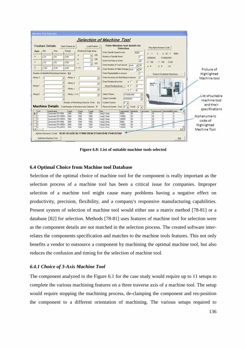
6.3 SELECTION OF SUITABLE MACHINE TOOL FOR THE COMPONENT..................................................................................... 133
6.4 OPTIMAL CHOICE FROM MACHINE TOOL DATABASE.................................................................................................... 136
6.4.1 Choice of 3-Axis Machine Tool ................................................................................................................ 136
6.4.2 Choice of 4-Axis Machine Tool ................................................................................................................ 138
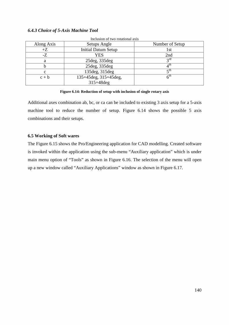
6.4.3 Choice of 5-Axis Machine Tool ................................................................................................................ 140
6.5 WORKING OF SOFT WARES ..................................................................................................................................... 140
vii
CHAPTER 7 – SUMMARY AND CONCLUSION ...................................................................................................... 152
7.4 FURTHER RESEARCH ............................................................................................................................................. 153
APPENDIX B – Possible combination of 3 and 5 axis machine tools
APPENDIX C – Arbitrary workpiece and its machining features
APPENDIX D – Pro/TOOLKIT programme code
APPENDIX E – Visual Basic programme code
APPENDIX F – Theory used in Software
APPENDIX G – Catalogue of Dugard VMC 660
APPENDIX H – BS4656-30
viii
LIST OF FIGURES
Figure 2.1: Cartoonist thought of control system on a machining centre [9] ............................................................. 11
Figure 2.2: A Centre Lathe ........................................................................................................................................... 12
Figure 2.3: Block Structure of a Lathe .......................................................................................................................... 13
Figure 2.4: Vragov’s Method Applied to a Milling Machine ........................................................................................ 14
Figure 2.5: Vargov’s representation of Xyz0Cv ............................................................................................................ 15
Figure 2.7: Representation of a Gantry milling machine ............................................................................................. 16
Figure 2.8: A Centre Lathe ........................................................................................................................................... 18
Figure 2.9: Representation of a Lathe by Portman’s method 6031 ............................................................................. 18
Figure 2.10: Layout of Model IR500PMF 4 [14] ........................................................................................................... 19
Figure 2.11: Representation of IR500MPF by Khomyakov 532016 (523222 0 126110) .................................................. 20
Figure 2.12: Representation of IR500MPF with its mounting plane ............................................................................ 21
Figure 2.13: Flow Chart of Ito and Shino’s Methodology ............................................................................................ 24
Figure 3.1: Creation of model in Pro/Engineer using design features ......................................................................... 28
Figure 3.2: Machining Features of the Component Defined by two Design Features ................................................. 28
Figure 3.3: Face Relation ............................................................................................................................................. 30
Figure 3.4: Feature Recognition using AAG ................................................................................................................. 31
Figure 3.5: Surface and Volumetric representation of features .................................................................................. 37
Figure 3.6: MRSEV features ......................................................................................................................................... 38
Figure 3.10: Parameters of a Slot Feature ................................................................................................................... 50
Figure 3.20: Parameters of a Pocket Feature .............................................................................................................. 56
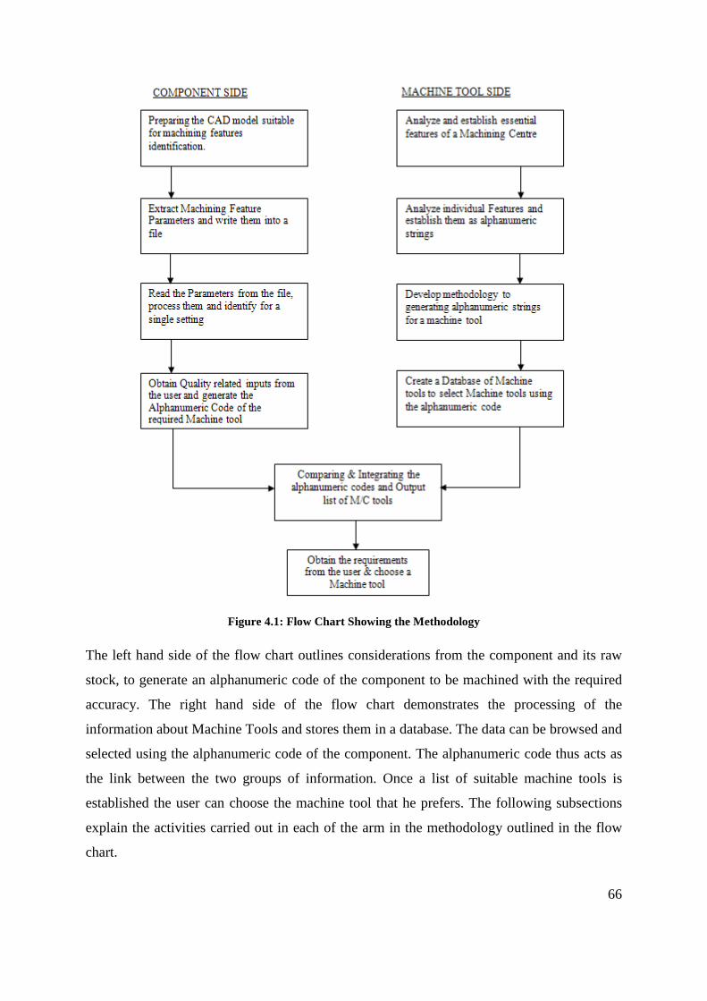
Figure 4.1: Flow Chart Showing the Methodology ...................................................................................................... 66
Figure 4.3: Vertical Milling Machine with Double Spindle ........................................................................................... 75
Figure 4.4: Material removal from raw stock .............................................................................................................. 77
Figure 4.5: Considered Machining Feature .................................................................................................................. 77
Figure 4.6: Machining Feature as described by Expert Machinist ............................................................................... 78
Figure 4.9: Machining Features (Expert Machinist) and the Object ............................................................................ 80
Figure 4.10: Making a Component with Cuts .............................................................................................................. 81
Figure 4.11: Feature Tree Showing the Design Feature Instances .............................................................................. 81
Figure 4.12: Feature Tree Using the Features Defined in Figure 4.6 (Proposed Machining Features) ....................... 82
Figure 4.13: Details of Entities Stored ......................................................................................................................... 83
Figure 4.14: CAD Model of Component 2 .................................................................................................................... 83
Figure 4.15: Creation of a Feature Based Model and its Feature Tree ........................................................................ 84
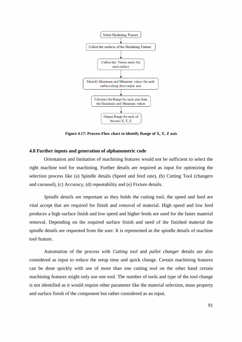
Figure 4.17: Process Flow chart to identify number of Setup ..................................................................................... 90
Figure 4.18: Process Flow chart to identify Range of X, Y, Z axis ................................................................................. 91
Figure 4.19: Intended marriage between alphanumeric code .................................................................................... 93
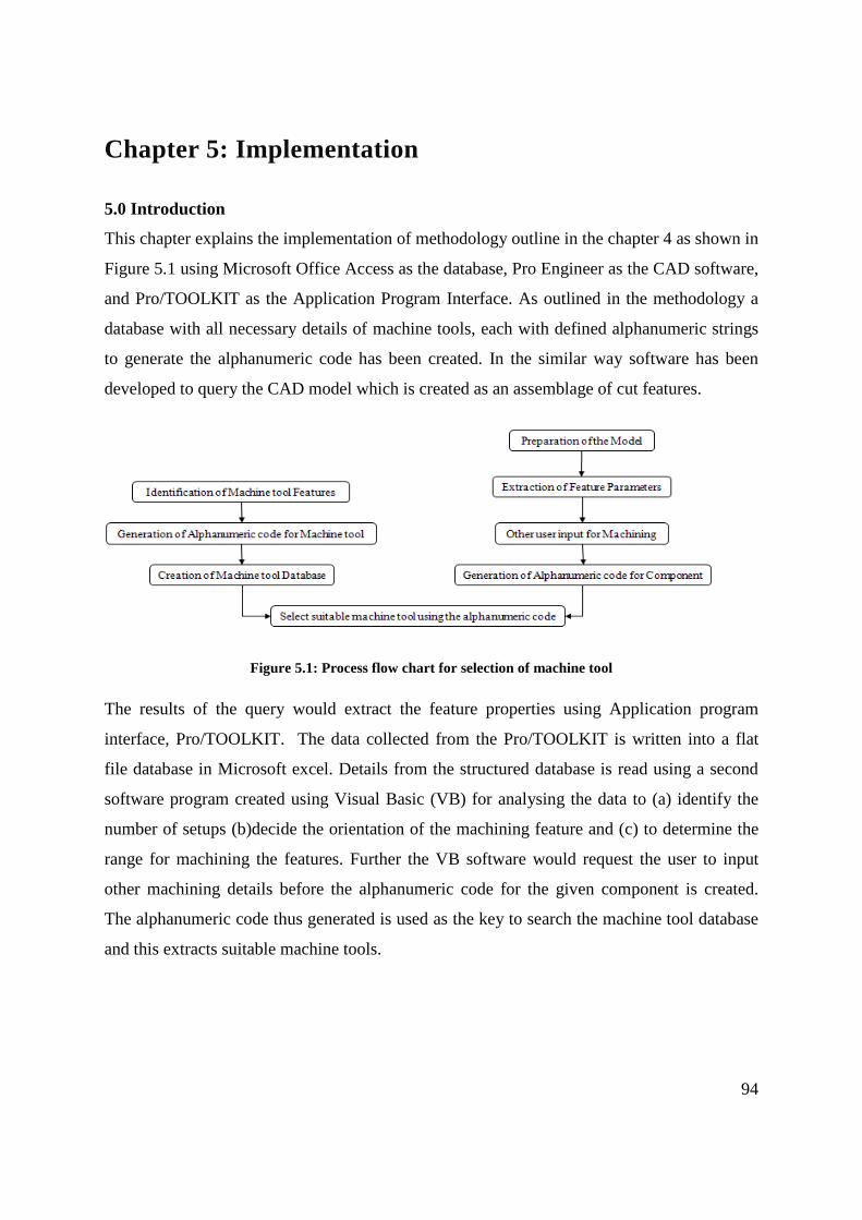
Figure 5.1: Process flow chart for selection of machine tool ...................................................................................... 94
Figure 5.2: Visual Basic program for database .......................................................................................................... 101
Figure 5.4: Preparation of model using material removal ......................................................................................... 106
Figure 5.5: Created Menu in Pro Engineer ................................................................................................................ 109
Figure 5.6: Starting Auxiliary Application in Pro Engineer ......................................................................................... 110
Figure 5.7: Component with Slot Feature ................................................................................................................. 111
Figure 5.8: Process of Surface selection from Machining Feature ............................................................................ 111
Figure 5.9: Entity Details of the Surface in database ................................................................................................. 113
Figure 5.10: Component with Slot Feature ................................................................................................................ 113
Figure 5.11: Process Flow of VB program .................................................................................................................. 116
Figure 5.12: Identified Machining Setups using VB Program .................................................................................... 117
Figure 5.13: Identified Range for Machining using VB Program ................................................................................ 117
Figure 5.14: VB form to collect sub-system feature of machining feature ................................................................ 118
Figure 5.15: Identified Alphanumeric Strings for the component in Figure 5.3 ........................................................ 119
Figure 5.16: User input for Machining the Component in Figure 5.3 ........................................................................ 120
Figure 6.1: Case Study Component ............................................................................................................................ 122
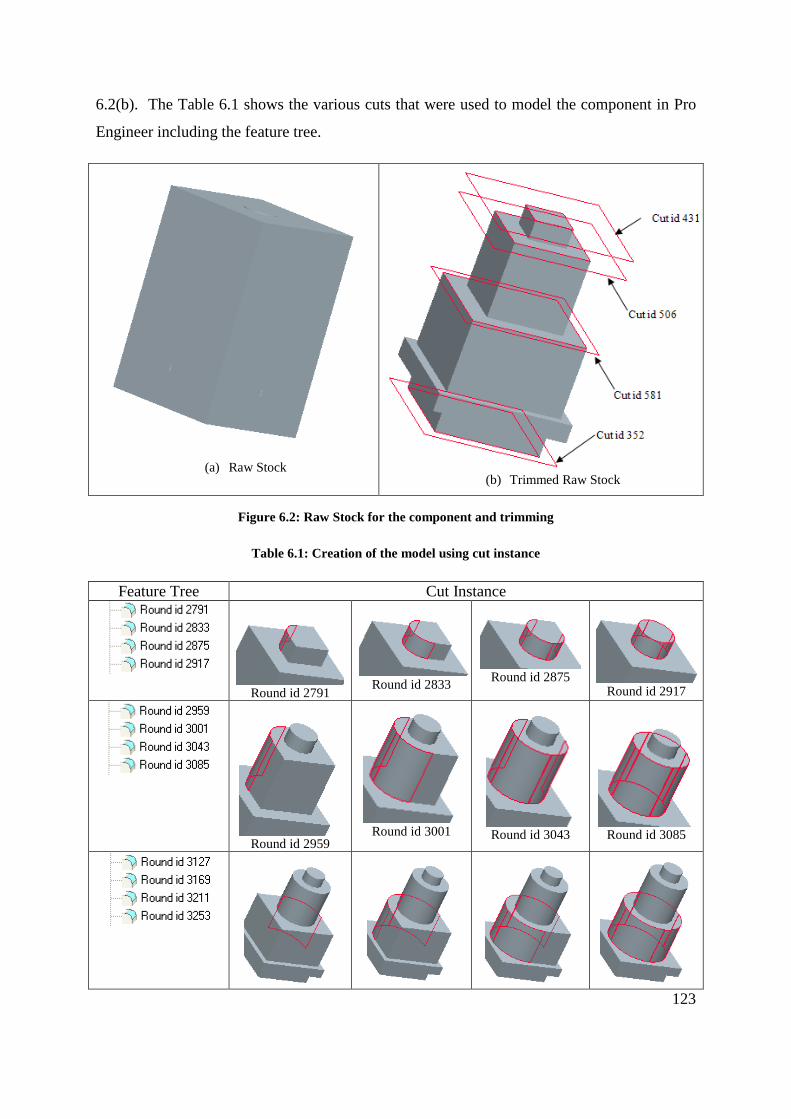
Figure 6.2: Raw Stock for the component and trimming .......................................................................................... 123
Figure 6.3: Sub menu created by API software ......................................................................................................... 125
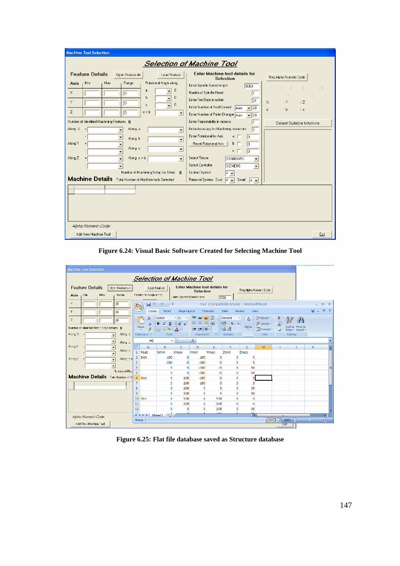
Figure 6.4: Software created using Visual Basic ........................................................................................................ 133
Figure 6.5: Identifying parameter from the data using created software ................................................................. 134
Figure 6.6: Second section to request user to input details for machine tool selection ........................................... 135
Figure 6.7: Section three of the software created using Visual Basic ........................................................................ 135
Figure 6.8: List of suitable machine tools selected .................................................................................................... 136
xii
Figure 6.9: Identified Machining Features populated along the axis ........................................................................ 137
Figure 6.10: Suitable Three Axes Machine Tool Selection ......................................................................................... 137
Figure 6.26: Saving Flat file to structure database .................................................................................................... 148
Figure 6.27: Identified details from structure data ................................................................................................... 148
Figure 6.28: Generation of Alphanumeric code for the component ......................................................................... 149
Figure 6.29: Selection of suitable machine tool using alphanumeric code ............................................................... 150
Figure 6.30: Window to add new machine tool to the database .............................................................................. 150
xiii
LIST OF TABLES
Table 2.1: Historical Developments of Machine Tool .................................................................................................... 9
Table 4.4: Number of Spindles .................................................................................................................................... 73
Table 4.5: Fixture Type ................................................................................................................................................ 73
Table 4.6: Controller Type ........................................................................................................................................... 73
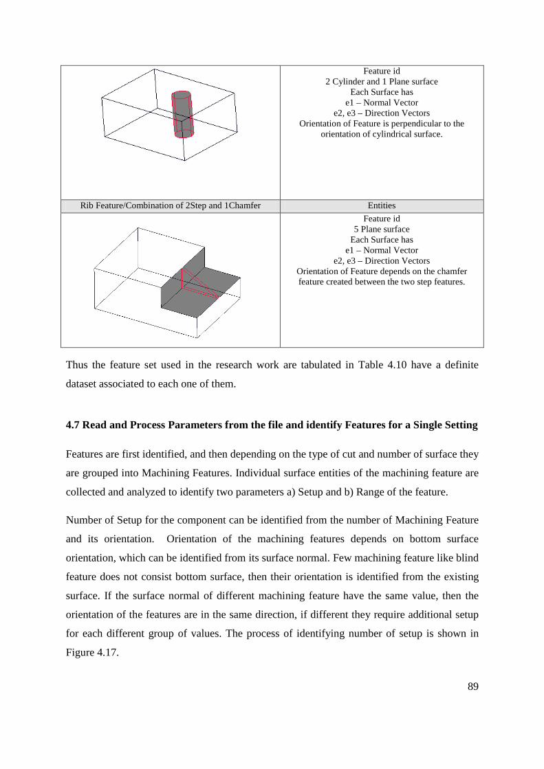
Table 4.10: Machining Features and its Entities .......................................................................................................... 85
xiv
Table 5 1: Manufacture Name & Model String ............................................................................................................ 95
Table 5.14: Example of Machine tool and its Alphanumeric Code ............................................................................ 103
Table 5.15: Machining Feature and its Surfaces ........................................................................................................ 107
Table 5.17: Second Surface ........................................................................................................................................ 112
Table 5.18: Third Surface ........................................................................................................................................... 112
Table 5.19: Pro/TOOLKIT Functions for Highlight ...................................................................................................... 114
Table 5.20: Pro/TOOLKIT function for Data ............................................................................................................... 116
Table 5.21: Alphanumeric Code of the component in Figure 5.3 .............................................................................. 120
xv
Table 6.1: Creation of the model using cut instance ................................................................................................. 123
Table 6.2: Idy Chamfer Menu .................................................................................................................................... 126
Table 6.3: Idy Round Menu ........................................................................................................................................ 126
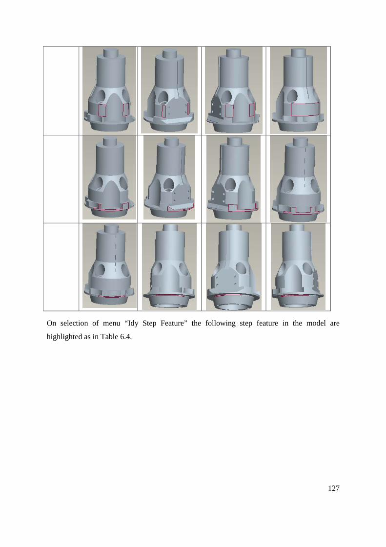
Table 6.4: Idy Step Menu ........................................................................................................................................... 128
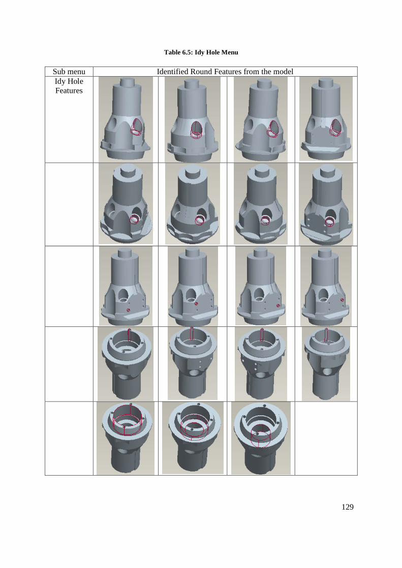
Table 6.5: Idy Hole Menu ........................................................................................................................................... 129
Table 6.6: Idy Pocket Menu ....................................................................................................................................... 130
Table 6.7: Data for all the identified machining features .......................................................................................... 130
Table 6.8: Setup angle and number of Setups ........................................................................................................... 137
1
Chapter 1: Introduction
Foresight [1] advocates that ‘Migration to Higher Value Added Service’ and ‘Restructuring of
Manufacturing Enterprises into Makers, Innovators and Integrators’ are some of the internal
responses of the manufacturing industry for the global manufacturing trends. Outsourcing is at
the heart of these responses. In simple terms outsourcing can be defined as the transfer of
services or functions previously performed within the organization to a provider outside the
organization. A lot of research work is being carried out on this new phenomenon, outsourcing.
However, Berggen, C. & Bengtsson, L. [2] identify that in Manufacturing Outsourcing the
research work is concentrated on management level (Buyer-supplier relationship) and work is
still to be done in linking Design and Manufacturing to the outsourcing framework.
Provision of metal cutting operations often called ‘Precision Engineering’ services, is a key
manufacturing activity in the UK. In the past all Original Equipment Manufacturer (OEM) had
the so-called precision engineering activity in-house, but many OEM’s now outsource this
activity to precision engineers.
Developments in cutting tools, coolants, drives, controls, tool changers, pallet changers and the
philosophy of machine tool design have made ground breaking changes in machine tools and
machining processes and the time taken for cutting is almost the same whether a sophisticated or
simple machine tool is used. Sophisticated machines are needed only to machine complex parts.
Thus the key task in outsourcing machining work is ‘the matching of the work to the machine
tool in which it can be manufactured’. This research is focussed on this and is aimed at
developing a systematic methodology to choose a machine tool of matching features to the
complexity of the machining job presented. In order to understand the implications and define
the aim and objectives of the work investigations were carried out under three broad topics.
They are
1. Historical development of Machine Tools
2. Change in Industrial Practice
3. The nature of the Components
2
Following sections gives a brief description of these and establish the aim and objectives of the
research.
1.1 Historical Overview of Machine Tools
Machine tool is a power driven appliance to bring the cutting tool and the work piece in contact
and to have a relative motion executing the cut that transforms the raw stock into a finished or
semi-finished component. Early Machine tools have specialized in a specific manufacturing
process or a collection of few such processes.
With developments rectifying all technological shortcomings a major rethink on functionality
took place. Similar to a shopping centre where one can find all types of goodies under one roof, a
‘Machining Centre’ capable of providing several functions which were traditionally performed
by different groups of machines such as mills, drills, shapers and so on was developed [3,4].
With the development of such machining centres the ability to know the capabilities of a
machine tool simply by looking at the name has become a thing of the past. While the process
names such as turning, end milling etc are used to describe the processes, the structure and
appearance of the machines that perform these operations can be completely different.
A major enhancement to Machine tools came from the development of controllers, which
controlled the functions such as motion, spindle, feed-rate, failure diagnostic, coolant, chip, tool
changers, pallet changers, memory storage etc. This has almost eliminated the need for skilled
machinists and substantially reduced idle time in machine tools. Researchers from the Soviet
Union like Vragov [5], Portman [6] and Voronov, [7] proposed various levels of coding system
to describe the structure of a machine tool. But no published work has appeared from them after
the fall of the Soviet Union. Ito and Shinno [8] provided the motion function as blocks to
represent machine tools system. This attempt again has not given any substantial result.
In summary, many motion providing functions are incorporated and controlled in a single
machine tool providing huge flexibility and the trend is to incorporate more functions. Limited
work has been done on developing a generic way to describe a machine tool. Furthermore
technological advancements created a trend that is ‘addition of more features to the already
3
complex machine tool to produce more complex components’. This has created the necessity
for a systematic methodology to represent the current and future machine tools.
1.2 Change in Industrial Practice
Roth [9] states that their transfer lines for the different automobile manufacturers were based on
the objective parts family consisting of the 4C’s, the Cylinder block, Cylinder head, Crankshaft
and Camshaft. Thus the fundamental considerations in the early machining centres were (a)
objective parts family and (b) generation of the required form generating functions. This is in
contrast to the situation created by outsourcing where the outsourcer and the precision engineer
do not know the other side. The ‘Precision Engineering Companies’ have a variety of machine
tools ranging from traditional lathes and milling machines to CNC machining centres and they
take contract work for these machines. They charge an hourly rate for the machine, operator and
the overhead for costing the work before adding a profit. The hourly rate for the machine
depends on the cost of the machine and thus the rate charged by different companies may vary
widely depending on which machine they intend to use for production. Therefore an easy
method to match the capabilities of the machine tool to the complexities of the component
to be machined is fundamental for outsourcers and precision engineers for economical and
high quality manufacture.
1.3 High Value-added Components
Within special industrial sectors such as the pharmaceutical, aeronautical and food engineering
there are a group of components that are called high value added components. These components
weigh few kilograms, machined out of standard stock and have special features. The cost of the
raw stock of these components are often less than one hundred pounds, but the finished
component costs several thousand pounds and the reason for the high cost is the high number of
features present in the components. They are often manufactured as one-offs and the features are
quality critical. They need to be manufactured using code generated by CAD/CAM software and
proven by simulation.
4
1.4 Statement of the Problem
Complex machine tools with varying capabilities have been and are being developed but no
generic method to describe the structure of the machine has been fully developed. Unlike in the
past the precision engineer does not know the work in advance to buy a suitable machine tool
and hence an easy way to choose a matching machine to a job is needed to facilitate outsourcing.
High value added components demand an easy way of generating, proving and transferring NC
codes from design to the machine tool. A methodology to describe the capability of a machine
tool and an easy way to choose matching machine tools to a given job is the fundamental
requirement and this thesis is aimed at addressing this requirement.
1.5 Aim and Objectives
Aim: The broad aim of this research is to develop a systematic methodology to choose a machine
tool of matching features to the complexity of the machining job presented.
Objectives:
1. To classify Machine Tools based on considerations of axes, sizes, spindles, tool
magazines, palettes, controllers etc. and the development of an alphanumeric code to
represent a machine uniquely.
2. To develop a sample database of commercially available machine tools from which
machine tools with common alphanumeric code can be retrieved.
3. To extract machining features and relevant information from a CAD model produced by
Pro/Engineer using the API, Pro-toolkit
4. To choose required machining characteristics features to generate the alphanumeric code
of the machine tools suitable for the given machining job.
5. To develop a software incorporating facilities to achieve the above objectives and the
required interfaces for inputting and outputting.
1.6 Summary Findings
Literature survey on Machine tools identified three major points. They are
5
i. Advancements of Machining Technology have reached a point where high quality tools
have been developed, coolants are devised, control systems and controllers were
developed, drive technologies were improved and better design methods were employed.
Machining Centres capable of performing several processes traditionally carried out by
different machines were developed. Analysis of some of the commercially available
machine tools pointed that there are machine tools which have a widely varied motion
functions and degrees of freedom and the trend towards the future is to have further
increase in sophistication due to addition of more degrees of freedom.
ii. Block structure of a Machine Tool divided it into two sections as the main flow of forces
and sub flow or forces. This laid the foundation for the method of describing a Machine
Tool by an Alphanumeric string.
iii. Shino and Ito have presented a design methodology for a Machine Tool. This highlights
that the primary step is to provide the motion functions in block structure, which is then
enhanced by structural design methods for mechanical properties. This shows that future
machines can have more blocks providing more complex motion functions. This has been
useful in the development of the alphanumeric code.
These are described in Chapter 2. In a similar fashion survey on machining revealed that
machining operations can be best described by Machining Features. Two ‘Feature Sets’, one
provided by ISO through their standard ISO 10303 and the other provided by Expert Machinist,
an additional software module in Pro/Engineer suite, have been discussed in Appendix I.
From these the critical surface characteristics to describe machining features were established. A
new set of cut features, were developed from them.
Based on the findings from the literature a two branch methodology to match the work with the
capabilities of the machine tool was established. The established methodology was implemented
as bolt-on software with CAE package (Pro/Engineer) using its Application Programmer’s
Interface, Pro/Toolkit. A matching database of commercially available machine tools also was
created. The developed software has been tested with several high value added components for
validity.
6
1.7 Structure of the thesis
Chapter 2 provides analysis of traditional machine tools, and the technological developments that
led to the development of machining centres. It further discuss about various research work that
was carried out to represent machining tools using codes and structural layout.
Chapter 3 sees feature based machining as an efficient way for planning machining. It therefore
provides a comprehensive survey on feature based machining. From the survey the important
characteristics for machining planning were identified. Two sets of machining features were
found to be complete. One of them was followed in the project and when that became
unavailable in the market a new feature set was defined. This chapter describe them.
Chapter 4 describes the methodology to choose a machine tool of matching capability to those
required by the complexity of the component.
Chapter 5 describes the implementation of the methodology using Access database, Pro Engineer
for CAD, Pro/TOOLKIT for application program interface and Visual Basic to analysis and
select the suitable choice of machine tool for the component using the alphanumeric codes.
Chapter 6 provide a detailed case study to show the process of creation of the workpiece as cuts
(mimicking material removal) in CAD, identification of machining features using Pro/TOOLKIT
generation of alphanumeric codes and selection of suitable machine tool for machining.
Chapter 7 discusses the results of the research work and draws conclusions.
The appendixes included in the project are
APPENDIX A – Brief history Machine Tool Survey
APPENDIX B – Possible combination of 3 and 5 axis machine tools
APPENDIX C – Arbitrary workpiece and its machining features
APPENDIX D – Pro/TOOLKIT programme code
APPENDIX E – Visual Basic programme code
APPENDIX F – Theory used in the Software
7
APPENDIX G – Catalogue of Dugard VMC 660
APPENDIX H – BS4656-30 Standards
8
Chapter 2 Literature Survey – Machine Tools
2.0 Introduction
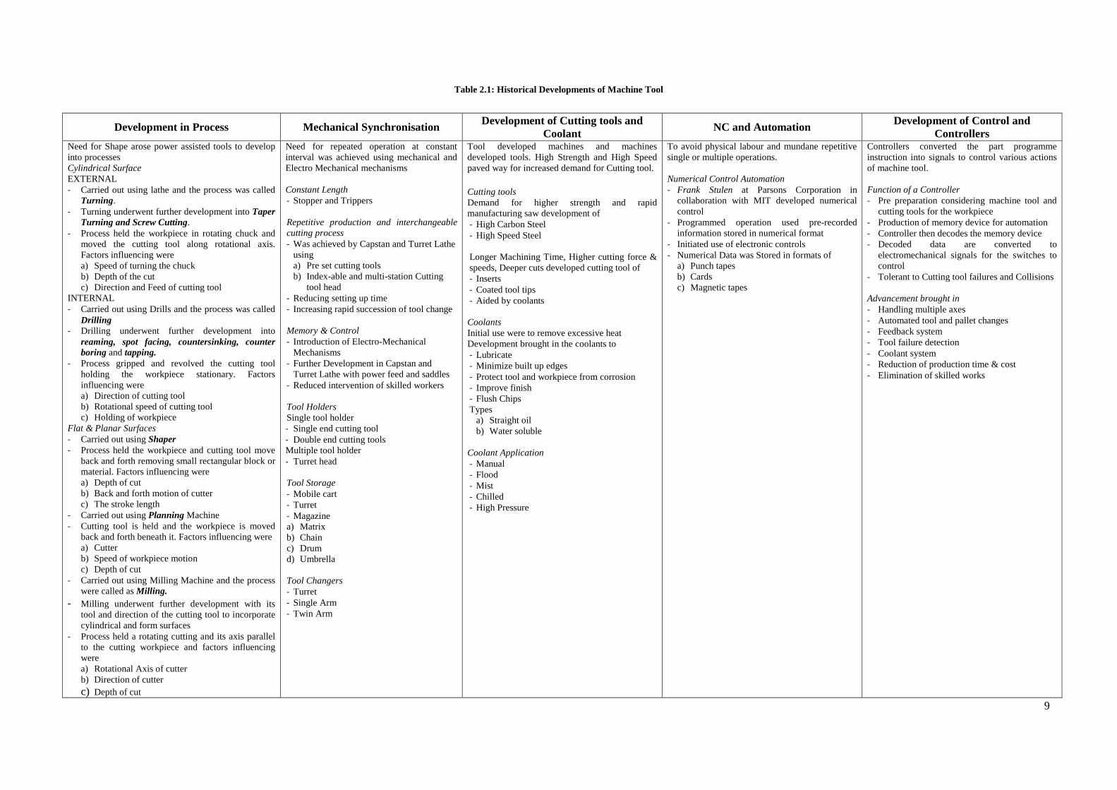
For the purpose of classifying the machine tools according to its capabilities and usage
complexities a study on the use perspective was needed and Table 2.1 shows the essence of a
comprehensive survey on traditional machine tools from the use perspective. It describes the
developments under the following five categories:
• Development in the Processes
• Mechanical Synchronisation
• Development of Cutting Tools and Coolants
• Early NC and Automation
• Development of Controls and Controllers
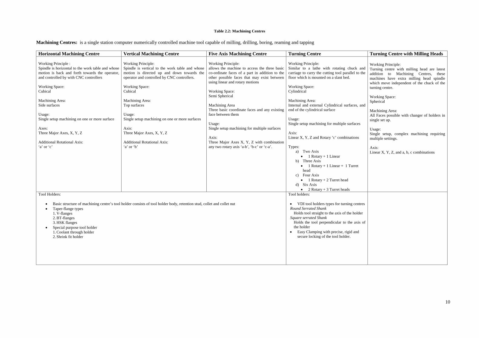
Machining Centres perform a multitude of tasks. A detailed survey of machining centres was
carried out and the details can be categorised into the following for easy comprehension.
• Horizontal machining centres
• Vertical machining centres
• Five axis machining centres
• Turning Centres
• Turning Centre with Milling Heads
The details of the findings are summarised in Table 2.2.
9
Table 2.1: Historical Developments of Machine Tool
Development in Process Mechanical Synchronisation Development of Cutting tools and Coolant NC and Automation Development of Control and
Controllers Need for Shape arose power assisted tools to develop into processes Cylindrical Surface EXTERNAL - Carried out using lathe and the process was called
Turning. - Turning underwent further development into Taper
Turning and Screw Cutting. - Process held the workpiece in rotating chuck and
moved the cutting tool along rotational axis. Factors influencing were a) Speed of turning the chuck b) Depth of the cut c) Direction and Feed of cutting tool
INTERNAL - Carried out using Drills and the process was called
Drilling - Drilling underwent further development into
reaming, spot facing, countersinking, counter boring and tapping.
- Process gripped and revolved the cutting tool holding the workpiece stationary. Factors influencing were a) Direction of cutting tool b) Rotational speed of cutting tool c) Holding of workpiece
Flat & Planar Surfaces - Carried out using Shaper - Process held the workpiece and cutting tool move
back and forth removing small rectangular block or material. Factors influencing were a) Depth of cut b) Back and forth motion of cutter c) The stroke length
- Carried out using Planning Machine - Cutting tool is held and the workpiece is moved
back and forth beneath it. Factors influencing were a) Cutter b) Speed of workpiece motion c) Depth of cut
- Carried out using Milling Machine and the process were called as Milling.
- Milling underwent further development with its tool and direction of the cutting tool to incorporate cylindrical and form surfaces
- Process held a rotating cutting and its axis parallel to the cutting workpiece and factors influencing were a) Rotational Axis of cutter b) Direction of cutter c) Depth of cut
Need for repeated operation at constant interval was achieved using mechanical and Electro Mechanical mechanisms Constant Length - Stopper and Trippers Repetitive production and interchangeable cutting process - Was achieved by Capstan and Turret Lathe
using a) Pre set cutting tools b) Index-able and multi-station Cutting
tool head - Reducing setting up time - Increasing rapid succession of tool change Memory & Control - Introduction of Electro-Mechanical
Mechanisms - Further Development in Capstan and
Turret Lathe with power feed and saddles - Reduced intervention of skilled workers Tool Holders Single tool holder - Single end cutting tool - Double end cutting tools Multiple tool holder - Turret head Tool Storage - Mobile cart - Turret - Magazine a) Matrix b) Chain c) Drum d) Umbrella Tool Changers - Turret - Single Arm - Twin Arm
Tool developed machines and machines developed tools. High Strength and High Speed paved way for increased demand for Cutting tool. Cutting tools Demand for higher strength and rapid manufacturing saw development of - High Carbon Steel - High Speed Steel Longer Machining Time, Higher cutting force & speeds, Deeper cuts developed cutting tool of - Inserts - Coated tool tips - Aided by coolants Coolants Initial use were to remove excessive heat Development brought in the coolants to - Lubricate - Minimize built up edges - Protect tool and workpiece from corrosion - Improve finish - Flush Chips Types
To avoid physical labour and mundane repetitive single or multiple operations. Numerical Control Automation - Frank Stulen at Parsons Corporation in
collaboration with MIT developed numerical control
- Programmed operation used pre-recorded information stored in numerical format
- Initiated use of electronic controls - Numerical Data was Stored in formats of
a) Punch tapes b) Cards c) Magnetic tapes
Controllers converted the part programme instruction into signals to control various actions of machine tool. Function of a Controller - Pre preparation considering machine tool and
cutting tools for the workpiece - Production of memory device for automation - Controller then decodes the memory device - Decoded data are converted to
electromechanical signals for the switches to control
- Tolerant to Cutting tool failures and Collisions Advancement brought in - Handling multiple axes - Automated tool and pallet changes - Feedback system - Tool failure detection - Coolant system - Reduction of production time & cost - Elimination of skilled works
10
Table 2.2: Machining Centres
Machining Centres: is a single station computer numerically controlled machine tool capable of milling, drilling, boring, reaming and tapping
Horizontal Machining Centre Vertical Machining Centre Five Axis Machining Centre Turning Centre Turning Centre with Milling Heads Working Principle : Spindle is horizontal to the work table and whose motion is back and forth towards the operator, and controlled by with CNC controllers Working Space: Cubical Machining Area: Side surfaces Usage: Single setup machining on one or more surface Axes: Three Major Axes, X, Y, Z Additional Rotational Axis: ‘a’ or ‘c’
Working Principle: Spindle is vertical to the work table and whose motion is directed up and down towards the operator and controlled by CNC controllers. Working Space: Cubical Machining Area: Top surfaces Usage: Single setup machining on one or more surfaces Axis: Three Major Axes, X, Y, Z Additional Rotational Axis: ‘a’ or ‘b’
Working Principle: allows the machine to access the three basic co-ordinate faces of a part in addition to the other possible faces that may exist between using linear and rotary motions Working Space: Semi Spherical Machining Area Three basic coordinate faces and any existing face between them Usage: Single setup machining for multiple surfaces Axis: Three Major Axes X, Y, Z with combination any two rotary axis ‘a-b’, ‘b-c’ or ‘c-a’.
Working Principle: Similar to a lathe with rotating chuck and carriage to carry the cutting tool parallel to the floor which is mounted on a slant bed. Working Space: Cylindrical Machining Area: Internal and external Cylindrical surfaces, and end of the cylindrical surface Usage: Single setup machining for multiple surfaces Axis: Linear X, Y, Z and Rotary ’c’ combinations Types:
a) Two Axis • 1 Rotary + 1 Linear
b) Three Axis • 1 Rotary + 1 Linear + 1 Turret head
c) Four Axis • 1 Rotary + 2 Turret head
d) Six Axis • 2 Rotary + 3 Turret heads
Working Principle: Turning centre with milling head are latest addition to Machining Centres, these machines have extra milling head spindle which move independent of the chuck of the turning centre. Working Space: Spherical Machining Area: All Faces possible with changer of holders in single set up. Usage: Single setup, complex machining requiring multiple settings. Axis: Linear X, Y, Z, and a, b, c combinations
Tool Holders:
• Basic structure of machining centre’s tool holder consists of tool holder body, retention stud, collet and collet nut • Taper-flange types
1. V-flanges 2. BT-flanges 3. HSK flanges
• Special purpose tool holder 1. Coolant through holder 2. Shrink fit holder
Holds tool straight to the axis of the holder Square serrated Shank
Holds the tool perpendicular to the axis of the holder
• Easy Clamping with precise, rigid and secure locking of the tool holder.
11
2.1 Contemporary Assessment
A modern machining centre is comparable to an orchestra as depicted in Figure 2.1. In the
orchestra each artist adds an instrument and the master controls the harmonious integration.
In the machining centre the controller controls the various shape changing functions in terms
of relative motions. The machining centre can have few motion functions forming a simple
machining centre or several motion functions forming a complex machining centre. Future
developments may add even more functions. This aspect is well demonstrated in the cartoon
used by Ingersoll Machine Tools [9].
Figure 2.1: Cartoonist thought of control system on a machining centre [9]
From the preceding analyses it can be said that a modern machining centre can be described
as a collection of motion function producing elements capable of producing several
combinations to produce the relative motions necessary for specific cutting operations. Future
developments would add more motion functions for further complex cutting. Thus the code
structure generated should not only be able to describe the existing motion functions
but also should be flexible to add future addition of functions.
12
2.2 Block Structure for Representing Machine Tools
Ito & Shinno [10, 11] state that a machine tool can be described as a combination of
structural modules determined in accordance with the shape, dimension and machining
condition of the work pieces to be machined. Such a ‘Machine Tool Structure as a Whole’
can be described as a Structural Pattern. They divide the flow of force in a machine tool into
two portions namely (a) main flow (tool side) and (b) sub-flow (work-piece side). From this
the structural configuration of the whole machine tool can be divided into two parts (a) sub-
structure for the main-flow of force and (b) sub-structure for the sub-flow of force. Forces
originate at the cutting point and propagate towards the foundation in both main and sub-
flow. They are transferred across the donor and receiver modules until they reach the bed and
hence the foundation. They continue to describe the forms the modules can take and their
dimensions. The main contribution of this method to the research conducted by the author is
the ability to describe a machine tool as a train of modules or blocks. The method is crucial
for understanding the succeeding sections and therefore a worked example is given here to
explain the process.
Figure 2.2: A Centre Lathe
13
Consider the lathe shown in Figure 2.2 which can be treated as an assemblage of two sets of
moving parts, one carrying the work piece and the other carrying the tool, both of which are
connected to the bed. Considering the tool, the moving parts are a) tool post b) turn table c)
cross slide and d) carriage which are in turn connected to the stationary structure, the bed.
This is the pattern of the Main Flow of Forces. Each of these is represented as a block. On the
other side the chuck which carries the work piece is also connected to the same bed through
the headstock. This forms the sub flow of forces. These parts can be stationary or perform
either a) translatory motion (that follows linear path) or b) rotary motions (that follows
circular path). There can be translatory or rotary motions along any of the three major axes.
Each part with its respective motion along with axes direction can be represented as an
individual block. The lathe can now be represented as a linkage of blocks as shown in Figure
2.3. The machining space (shaded part) is the area between the tool and the worktable, which
is also represented as a block.
M achin ing Space
M ain Flow of Force
Sub Flow of Force
Z
YX
Bed
Turn Table forTool Post
Lathe B ed
Cross Slide
Tool Post
Carriage
Chuck and Spindle
Figure 2.3: Block Structure of a Lathe
14
Block structure can be used to represent any machine tool that would consist of a single block
to represent the workspace and numerous other blocks for the various motions performed on
the machine tool. Number of blocks used in a representative block structure would vary with
respect to number of moving and stationary parts in a machine tool.
2.3 Structural Representation in Sympathy with Block Structure Representation
Most of the work done in analysing structural layouts of machine tools has been done in the
Soviet Union. In this section some of these methods have been described. Vragov’s [5, 13]
method, which is widely cited, is described first. Portman’s [6] method of developing a
numeric code is used is discussed second. Thirdly Khomyakov and Davydov [12, 14]
proposed a code system at different levels of abstraction, which is followed by other research
like Voronovo [7] who also worked in representing the machine tool with tool and pallet
changing system.
2.3.1 Vargov’s Method
1X
Z
2
3
4
5Y
Figure 2.4: Vragov’s Method Applied to a Milling Machine
Vargov [5, 13] method uses block structure, represented using symbols to describe the
machine tool layouts. Considering the knee type milling machine shown in Figure 2.4 which
has a cutting spindle attached on one end of the structure and three moving blocks on the
other end of the fixed structure. The bed, the stationary block 4, is represent as ‘0’, whilst
three moving block 1,2,3 are represented by letters corresponding to motions of the axes
(Right hand coordinate system nomenclature) X, Y and Z respectively. The cutting spindle,
15
block 5, rotating about the Z axis is represented as C. Thus the blocks involved can be
represented as XYZOC.
The block structure not only includes information about forming and setting motion’s
direction but also number of spindles and its orientation towards work piece. Upper case
letters are used to represents forming motion and lower case letters are used for auxiliary or
setting motion. The main spindle in the knee type, milling machine is vertical to that of the
worktable, which is represented using suffix ‘v’ for vertical and ‘h’ if horizontal to the block
representing the spindle motion. More than one identical spindle is represented by numerical
digit in front of the spindle block, while parallel linking is represented by ‘+’ signs and
separated by bracket. Linking of block of motion in a machine tool is without any symbol
between them. The block carrying work piece is represented on the far left, whilst a block
carrying the tool is represented on the far right with the consecutive blocks in middle. Thus
the knee type, milling machine shown in Figure 2.4 is represented as 'XyzOCv' in Figure 2.5.
It is worth noting that motions along the Y axis and Z axis have been treated as auxiliary and
motions represented by the X and C are treated as cutting motions. The suffix v along C
indicates that the spindle is vertical.
Figure 2.5: Vargov’s representation of Xyz0Cv
Logical algebra is used to illustrate the consecutive linking of blocks as conjunction (AND
function) and parallel linking as disjunction (OR), permitting machine tool structure of any
complexity to be represented. An expression of combination of symbols thus represents (a)
the structure of the machine layout, (b) the number and type of the forming and auxiliary
16
motions, (c) the order of linking and the (d) direction of the coordinate displacement of the
blocks, (e) the distribution of elementary motions between the work piece and tool and, (f)
the type of basic layout and the design arrangement of the blocks.
Considering the gantry type, milling machine as shown Figure 2.6 consist of a worktable
connected to the base structure. Worktable performs the setting motions and has a translator
motion along Y axis, which is in turn connected rotational axis along Z. The structure further
consist of two cutting tool heads connected to structure a) to move along Z axis consisting of
five spindle and b) to move along X axis consisting or five spindle head. This can be
represented as “Yc + 0ZC5v + 0XA5h” as shown in Figure 2.7.
X
Z
Y
Figure 2.6: Gantry Milling Machine
Yc + 0ZC5v + 0XA5h
Figure 2.7: Representation of a Gantry milling machine
17
2.3.2 Portman’s Method
Portman [6] method described a machine tool using block structure and numerical symbols.
Representation of numerical symbols is in continuous chain from the worktable to the cutting
tool. The configuration is written in two stages.
The first one composes the 'code k ' for the machine tool form generating chain:
nkkkk −−= 21
In the second, the designation of the frame position is introduced
Writing the code k for the machine tool form generating chain
The code k for the machine tool form generating chain is given by
nkkkk −−= 21
Where
n is the number of moving links in the chain
1k to kn is the designation according to Table 2.3 of the motion of the first link in the form
generating chain with respect to the workpiece which is rigidly connected to the subassembly
e.g. the work clamped to the spindle of a lathe.
In this manner k is a number with as many digits as there are moving subassemblies in the
machine tool and each digit may assume value 1 to 6.
Table 2.3: Numeric Symbol representing motion
Symbol Motion with respect to preceding link 1 Translatory along the X axis 2 Translatory along the Y axis 3 Translatory along the Z axis 4 Rotatory about X axis 5 Rotatory about Y axis 6 Rotatory about Z axis
Introducing the Fixed Frame
In the code describing the configuration fixed frame are represented using '0'. In the sequence
of links from work piece to the tool if the fixed frame is the ith then introduce a '0' at the ith
position. As an example consider a centre lathe shown in Figure 2.8.
18
X
Y
Z
d
w
Figure 2.8: A Centre Lathe
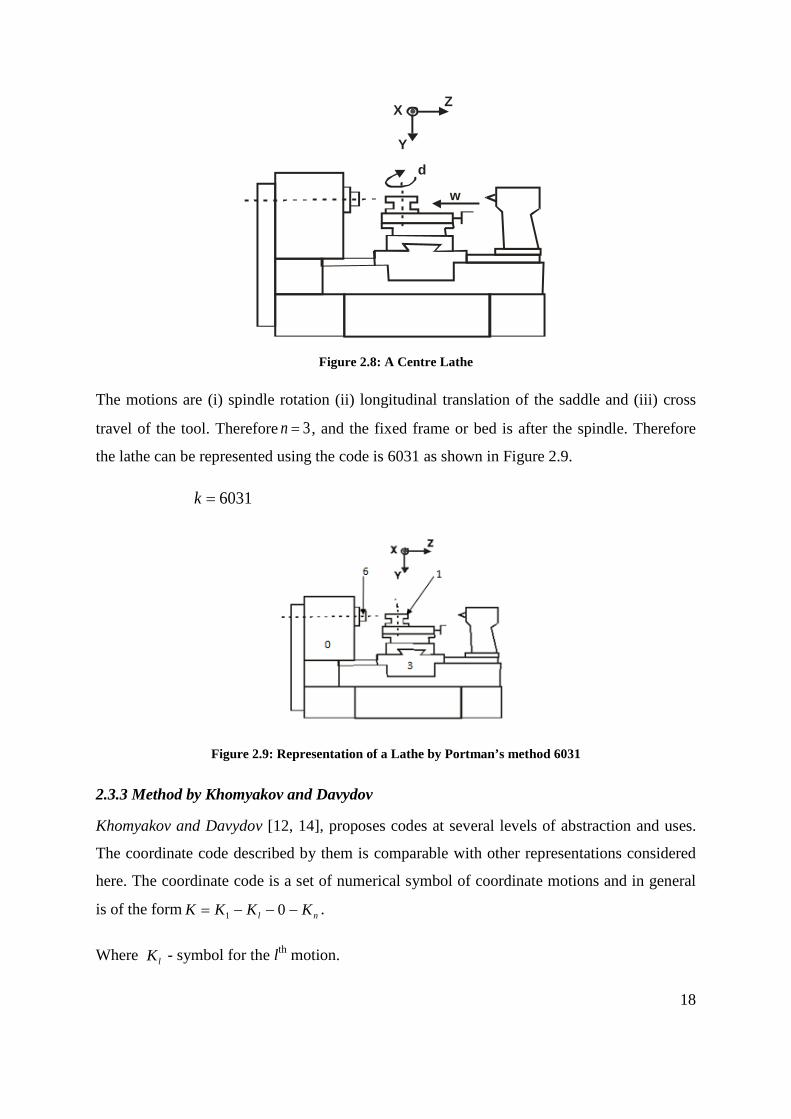
The motions are (i) spindle rotation (ii) longitudinal translation of the saddle and (iii) cross
travel of the tool. Therefore 3=n , and the fixed frame or bed is after the spindle. Therefore
the lathe can be represented using the code is 6031 as shown in Figure 2.9.
6031=k
Figure 2.9: Representation of a Lathe by Portman’s method 6031
2.3.3 Method by Khomyakov and Davydov
Khomyakov and Davydov [12, 14], proposes codes at several levels of abstraction and uses.
The coordinate code described by them is comparable with other representations considered
here. The coordinate code is a set of numerical symbol of coordinate motions and in general
is of the form nl KKKK −−−= 01 .
Where lK - symbol for the lth motion.
19
n – Number of motions realised in the layout
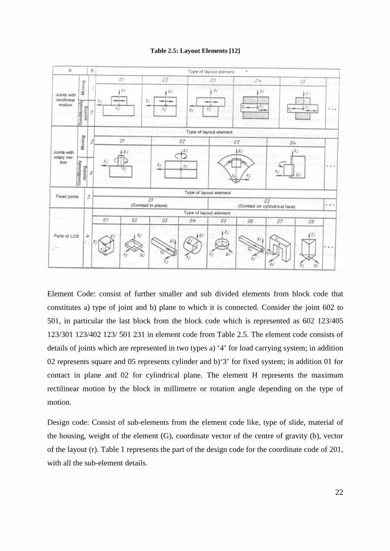
Figure 2.10: Layout of Model IR500PMF 4 [14]
lK can have whole number values from 1 to 6; As with Portman’s method Digits 1 to 3
represent rectilinear motions along the X, Y and Z directions and 4, 5 and 6 represent rotation
relative to these axes. 0 is the divider between the tool and workpiece branches (fixed block).
Symbol lK is written with a superscript taking the values 0, 1 or 2 indicating the following:
0 – Setting motion (for example changing the tool or blank)
1 – Setting motion linked with machining (setting for machining a part with a given tool)
2 – Working motion needed for realizing the forming process.
The coordinate code thus represents the following properties of the layout:
a. Number and types of motion provided (reciprocator or rotary)
b. Orientation of the axes on or about which the motions are made
c. Sequence of the motions
d. Distribution among the tool branch and workpiece branch
20
Coordinate Code: for the machine IR500PMF 4 in Figure 2.10 is 532016 (523222 0 126110),
which represents each motion of a block is defined by a number, where in turn 1,2,3
represents the Translator motions of X, Y, Z and 4,5,6 represents rotary motions along X,Y,
Z respectively. Figure 2.11 represents the coordinate code of the IR500PMF 4. Non moving
block of the element is represented as ‘0’. Further the joints between the motions can be used
to represent them as forming or setting motions as postscripts of 2 and 1 respectively.
Prabhakar & Henderson Neural Network X X X X X X X X X
Ding & Yue ANN X X X X X X X X
45
3.4 Combination or Hybrid Approaches
Hybrid methods are based on combination of Geometry, Feature and API based methods to
meet the challenges encountered in recognizing interacting features from a CAD model.
Marefat et al [21-23, 63] introduced a different hint-based approach, significantly extending
the classical graph-based approach to include uncertainty reasoning to avoid the
computational complexity that results from sub-graph isomorphism. In addition to face Ids,
the graph nodes contain information about their relative orientation and edges represented as
links contain concavity information. The cavity graphs of the part are extracted and
partitioned for, sub-graphs to be compared with existing feature templates for isomorphism.
If the sub-graphs cannot be verified, they are further analyzed for evidence by adding “virtual
links”. The Dempster-Shafer theory is utilized for uncertainty reasoning to provide the most
probable virtual links. Gao & Shah [36] used a Minimal Condition Sub-graph (MCSG) for
their reasoning. This is achieved by extending the classical attributed adjacency graph (AAG)
to create the Extended AAG (EAAG) in which both the faces (nodes) and edges (links) carry
extra information. Face attributes such as whether they belong to the stock or part, are Unifi-
able or not, are part of the convex hull or not, how many loops they have and their geometry
like vertices and faces are used as inputs. Edge attributes such straight or curved, be part of
the inner or outer loop of a face, smooth or sharp, in addition to being convex or concave,
and real or virtual are taken into consideration.
Manufacturing Face Adjacency Graphs (MFAGs) are readily recognized by eliminating stock
and convex hull faces. Partial patterns are called MCSGs and are treated as hints that need to
be completed via addition of virtual links. Reasoning for virtual links is done by dividing
feature interactions into six types, thus making it possible to generate multiple interpretations
by completing the graphs in alternative ways. Another method that modified the AAG
technique using hint based reasoning was introduced by Ibrahim and McCormack [64, 65].
Similar to Gao & Shah [36] approach, this technique increased the attributes of both edges
and faces; however the resulting AAG, called a Modified Attributed Adjacency Graph
(MAAG), was not broken down into sub-graphs. Instead, features are grouped into “families”
according to hints generated by “part surfaces“, which must be in constant contact with the
tip of the cutting tool which machine them. Seeking out faces with at least one concave edge
46
identifies part surfaces. For each such face adjacent faces with convex edges are retrieved,
thus creating an opening for that face. Special cases include through features, with no part
surface, and protrusions with associated surrounding part surfaces. New feature taxonomy is
created based on hints from the MAAG classifying features such as simple depressions,
protrusions, passages and multi-part surfaces. This work is further explained by Ibrahim and
McCormack [64, 65], and comes closest to hint-based reasoning among the approaches
mentioned in this subsection.
A hybrid method based using feature hints, graph theory and artificial neural network was
proposed by Li, Ong & Nee [66]. Modified AAG and API were used by Zhang et al. [67].
Volume subtraction and face adjacency graph method was proposed by Rameshbabu &
Shunmugam [68, 69]. Hint based and Rule based systems are utilized by Dimov et al. [70]
for feature recognition. Pal & Kumar [71] used feature algebra by Karinthi [72] combined
with heuristic rules to identify features. Each hybrid approach has proven to be effective in
recognizing interacting feature due their robustness and strong learning capability. Each
approach is effective in certain subtask of the interacting feature recognition process with
optimum efficiency; however satisfactory results cannot be achieved using a single method.
Extracting a complete set of machining features and their details were still not achieved.
Most systems use low-level features that are predefined in the CAD system’s libraries. But
higher-level features are more convenient to express the parts, domain specific functionality
and machining characteristics. In a hybrid approach, it is assumed that all machining features
can be machined in a single machine centre. Most components require multiple machining
centres [47] to achieve intricate machining details. In most cases the subsequent machining
details such as machine tool selection, operation selection, operation sequencing and
machining sequencing were not considered.
47
Table 3.4: Combination or Hybrid Approaches
Authors
Feat
ure
Rec
ogni
tion
Met
hod
Cat
egor
y
Full
Set
of M
achi
ning
Fea
ture
s Id
entif
ied
3D fe
atur
es
2.5D
/2D
feat
ures
Parti
al S
et o
f Mac
hini
ng F
eatu
res
Iden
tifie
d
Iden
tific
atio
n of
In
ters
ectin
g fe
atur
es
Com
poun
d / A
rray
Fea
ture
s
Aut
omat
ic F
eatu
re R
ecog
nitio
n
Prim
ary
Fact
or
for
feat
ure
reco
gniti
on
Tool
App
roac
h D
irect
ion
(TA
D)
Feat
ure
crea
ted
by D
esig
n
Dim
ensi
onal
D
etai
ls
of
Mac
hini
ng F
eatu
re
Ade
quac
y C
heck
of
mac
hini
ng
feat
ure
for m
anuf
actu
ring
Inte
grat
ion
with
CA
PP
Inte
grat
ion
with
CA
M
Stan
dard
of E
xcha
nge
STEP
-224
Heu
ristic
s Alg
orith
m
Impl
emen
ted
Met
hod
Sele
ctio
n of
Ava
ilabl
e M
achi
ne
tool
s St
and
alon
e Pr
ogra
m/S
oftw
are
Inte
grat
ion
with
CA
D S
yste
m
Rep
rese
ntat
ion
of fe
atur
es
Surf
ace
Edge
s
Des
truct
ion
Synt
hesi
s
Gao & Shah MCSG H
ybrid
X X X X X X X X X
Ibrahim & McCormack MAAG X X X X X X X X X
Li, Ong & Nee X X X X X X X X X
Zhang et al X X X X X X X X X
Rameshbabu & Shunmugam Hybrid X X X X X X X X X X X X X
Dimov et al X X X X X X X X
Pal & Kumar X X X X X X X X X X
48
A summary of all the feature recognition approaches with their major merits and demerits
with respect to machining capability are given summarized on each section. A substantial
knowledge has been generated in this area. The major hurdle however with all these
recognition techniques is that they do not consider a complete set. In addition the intersecting
features have not been given adequate consideration. These are the missing links in total
integration of CAD to CAPP and CAM.
International Standard Organisation developed ISO 10303-224 for describing machining
features as included in Appendix I, which primarily focused towards defining machining
features with intrinsic details. However the details covered are too extensive for the purpose
of identifying a matching machine tool.
Adequacy of machining features was first established by Chitroda & Sivaloganathan [73],
using the machining feature set provided by the Expert Machinist module of Pro/Engineer.
Expert Machinist is a feature based machining (milling) software bolted on to the
Pro/Engineer (CAD software) to simulate and create downwards activities in milling
application. Chitroda & Sivaloganathan considered fifty different machining components and
established that the machining feature set provided by Expert Machinist is adequate to define
any machining job. Srikumaran [74] had used feature mapping technique for identifying
manufacturability of components using expert machinist feature set which can be used as
early as design stage [75]. However PTC has withdrawn Expert Machinist thus forcing the
development of an adequate feature set. Adequacy of the new Machining Feature set would
be automatically established if the new set can replicate the features provided by Expert
Machinist. Such a new set of machining features is proposed in this thesis and is described in
the following section.
3.5 Surfaces and Surface Parameters Characterising Machining Features
Machining features are characterised by surfaces and each surface has its own parameters.
Machining features and their constitutive surfaces are discussed below.
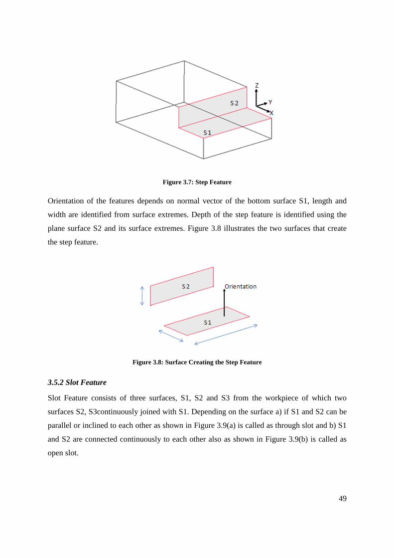
3.5.1 Step Feature
Step features is created by two plane surfaces from the workpiece S1 and S2 as shown in
Figure 3.7, both the surfaces continuously join together to form a V between them, the step
features parameters can be identified from the surfaces.
49
Figure 3.7: Step Feature
Orientation of the features depends on normal vector of the bottom surface S1, length and
width are identified from surface extremes. Depth of the step feature is identified using the
plane surface S2 and its surface extremes. Figure 3.8 illustrates the two surfaces that create
the step feature.
Figure 3.8: Surface Creating the Step Feature
3.5.2 Slot Feature
Slot Feature consists of three surfaces, S1, S2 and S3 from the workpiece of which two
surfaces S2, S3continuously joined with S1. Depending on the surface a) if S1 and S2 can be
parallel or inclined to each other as shown in Figure 3.9(a) is called as through slot and b) S1
and S2 are connected continuously to each other also as shown in Figure 3.9(b) is called as
open slot.
50
Figure 3.9: Slot Feature
Parameter of the slot features can be identified from the surfaces S1, S2 and S3, orientation of
the slot depends on the bottom surface S1, length, width can also be identified from the plane
surface S1’s surface extremes. The depth of the slot feature is identified from the plane
surface S2 or S3 from its surface extremes. Various parameters of the slot feature and the
three surfaces creating the slot feature is illustrated in Figure 3.10.
(a)
(b)
Figure 3.10: Parameters of a Slot Feature
3.5.3 Round Feature
Round Feature consist of single cylindrical surface S1 as shown in Figure 3.11.
51
Figure 3.11: Round Feature
Parameters of the round feature such as its orientation, dimensions are identified from the
cylindrical surface S1 and its surface extremes as shown in Figure 3.12.
Figure 3.12: Parameters of Round Feature
3.5.4 Planar Feature
Planar feature is made up of a single plane surface S1 from the workpiece as shown in Figure
3.13(a), some time the surface might consist of contour or island called as boss as illustrated
in Figure 3.13(b).
52
Figure 3.13: Planar Feature
Parameters of the planar feature such as its orientation, dimensions are identified from the
plane surface and its surface extremes as shown in Figure 3.14.
Figure 3.14: Parameters of Planar Feature
3.5.5 Chamfer Feature
Chamfer feature is made up of a single plane surface S1 from the workpiece as shown in
Figure 3.15.
53
Figure 3.15: Chamfer Feature
Parameter of a chamfer feature such as its orientation, dimensions are identified from the
plane surface S1 and its surface extremes as shown in Figure 3.16.
Figure 3.16: Parameter of Chamfer Feature
3.5.6 Hole Feature
Hole features is made up of two cylindrical surface called as through hole, or two cylindrical
and one plane surface blind hole from the workpiece. Figure 3.17 illustrates different kinds of
holes, a) if the cylindrical surfaces are parallel to each other they are straight hole and b) if
the cylindrical surfaces are inclined they are conical holes.
54
Figure 3.17: Hole Features
Parameters of a hole feature such as its orientation, dimensions are identified from the plane
surface in absence the cylindrical surface is used and its surface hole features surface
extremes are shown in Figure 3.18.
Figure 3.18: Parameter of Hole Feature
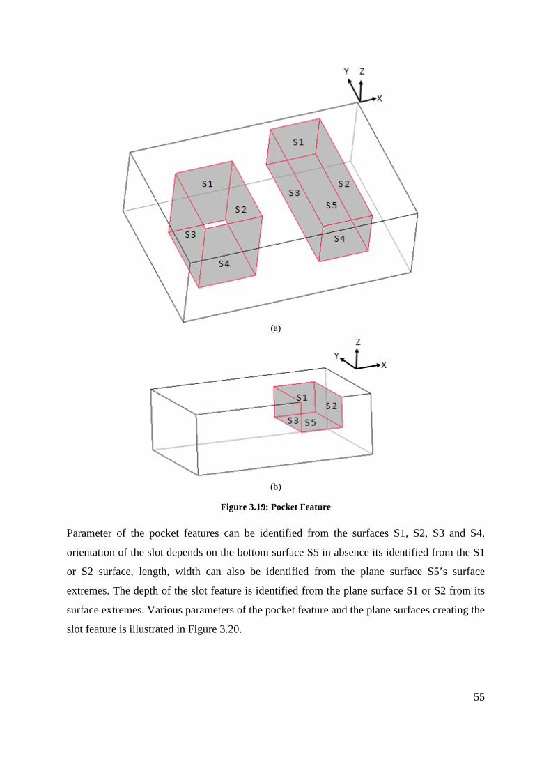
3.5.7 Pocket Feature
Pocket features is of three types a) through pocket which consist of four plane surfaces from
the workpiece of which pair of surfaces are parallel to each other, b) five plane surface of
which two sets are parallel to each other and these are connected to the fifth surface as shown
in Figure 3.19(a) and c) b) four plane surfaces from the workpiece of which two planes are
paralle1 and other two are perpendicular to each other as shown in Figure 3.19(b).
55
(a)
(b)
Figure 3.19: Pocket Feature
Parameter of the pocket features can be identified from the surfaces S1, S2, S3 and S4,
orientation of the slot depends on the bottom surface S5 in absence its identified from the S1
or S2 surface, length, width can also be identified from the plane surface S5’s surface
extremes. The depth of the slot feature is identified from the plane surface S1 or S2 from its
surface extremes. Various parameters of the pocket feature and the plane surfaces creating the
slot feature is illustrated in Figure 3.20.
56
(a)
(b)
(c)
Figure 3.20: Parameters of a Pocket Feature
This section thus highlights the geometric properties that are needed to analyse any
manufacturing feature. A lot of research work has been done [15], [17], [21], [27] on feature
definition and recognition methods, but their adequacy has never been checked. Chitroda and
57
Sivaloganathan [73]. have established that Expert Machinist features are adequate for
describing all machining operations performed in a Vertical Machining Centre. But
Pro/Engineer does not permit access to these machining feature parameters. A machining
feature set whose parameters are accessible was needed to achieve the objectives of the
research. Since the feature set provided by Expert Machinist was proven to be adequate a set
that can map all features in Expert Machinist has been developed. It is created to make bolt-
on to Pro/Engineer. Section 3.7 describes them.
3.6 Cuts as Machining Features and their Characteristic Surfaces and Parameters
The high level modelling entities of feature-based design can provide the necessary
information needed by applications to store and retrieve information of a particular feature.
Geometry issues depend on the feature creation methods supported by the modeller. The
classification of design features may vary for different solid modellers. Various design
features available in Pro/Engineer are;
• Protrusion • Cut • Chamfer • Hole
• Round • Rib • Shell • Pipe
The primary feature creation methods in part modelling are protrusions (mass additions) and
cuts (mass removal). Protrusions and cuts are created using 2-D cross sections that are
extruded, revolved, swept or blended in creating the required shapes. As machining is the
process of material removal, so a base is created as a protrusion considering as raw stock and
further cuts are added on to raw stock. The various cuts creating the machining features are
described below;
3.6.1 Step Feature
The Figure 3.21 illustrates the creation of a step feature using the design feature cut in
Pro/Engineer. 2D sketch is drawn as highlight in red colour such that the corner of the
drawing
58
Figure 3.21: Step Feature
coincides with that of the workpiece. The sketch is then swept across in the direction of the
arrow to create the cut to the full length, the material removed as this process is highlighted in
green. The material removed would created two plane surfaces which would form a V shape
between them to form the step feature
3.6.2 Slot Feature
The Figure 3.22 illustrates the creation of a slot feature using the design feature cut in
Pro/Engineer.
(a)
59
(b)
Figure 3.22: Slot Features
2D sketch is drawn as highlight in red colour such that the top end of the drawing coincides
with that of the workpiece. The sketch is then swept across in the direction of the arrow to
create the cut to the full length for through slot as shown in Figure 3.22(a). Open slot is
created with a 2D sketch that coincided to the corner of the workpiece and swept to a limited
distance and not throughout as shown in Figure 3.22(b). Outcome of the design process
would result in material removed as highlighted in green. The material removed would create
three plane surfaces which would form the slot feature.
3.6.3 Round Feature
The Figure 3.23 illustrates the creation of a round feature using the design feature round in
Pro/Engineer. The edge on which the round has to be created is selected as highlight in red
colour, and the radius for rounding is designated. The outcome of the design process in
Pro/Engineer will result in removal material from the base to create a single cylindrical
surface on the edge selected as shown in Figure 3.23.
60
Figure 3.23: Round Feature
3.6.4 Planar Feature
The Figure 3.24 illustrates the creation of a planar feature using the design feature cut in
Pro/Engineer. 2D sketch is drawn as highlight in red colour such that the outline of the
workpiece coincides with that of the drawing. The sketch is then swept across in the direction
of the arrow and swept to a limited distance and not throughout as shown in Figure 3.24(a).
Creation of a small island of material within the process creates the bosses as shown in Figure
3.24(b) Material removed as this process is highlighted in green. The material removed
would create single plane surface which would form the planar feature.
(a)
61
(b)
Figure 3.24: Planar Feature
3.6.5 Chamfer
The Figure 3.25illustrates the creation of a Chamfer feature using the design feature chamfer
in Pro/Engineer. The edge on which the chamfer has to be created is selected as highlight in
red colour, and the angle and length of the chamfer is designated. The outcome of the design
process in Pro/Engineer will result in removal material from the base to create a single plane
surface on the edge selected as shown in Figure 3.25.
Figure 3.25: Chamfer Feature
62
3.6.6 Hole
The Figure 3.26 illustrates the creation of a Chamfer feature using the design feature hole in
Pro/Engineer. The surface on which the hole has to be created is selected and referenced, the
hole diameter is designated if its straight hole as shown in Figure 3.26 or a conical hole is
sketched. The outcome of the design process in Pro/Engineer will result in removal of
material from the base to create a two cylindrical surface for through hole and a two
cylindrical and a plane surface for a blind hole.
Figure 3.26: Hole Feature
3.6.7 Pocket
The Figure 3.27 illustrates the creation of pocket feature using the design feature cut in
Pro/Engineer. 2D sketch is drawn as highlight in red colour such that the sketch is within the
workpiece. The sketch is then swept across in the direction of the arrow to create the cut to
the full length for through pocket as shown in Figure 3.27(a) and blind pocket is created with
limited distance as shown in Figure 3.27(b). Open pocket is created with a 2D sketch that
coincided to the edge of the workpiece and swept to a limited distance and not throughout as
shown in Figure 3.27(c). Outcome of the design process would result in material removed as
highlighted in green. The material removed would create a) four plane surfaces for open and
through pocket and b) five plane surfaces for a blind pocket.
63
(a)
(b)
(c)
Figure 3.27: Slot Feature
3.7 Chapter Summary
The survey on Machining has been carried out to understand Machining Process and the
modelling approach (Machining Feature approach) taken to model them. The following can
be said as the summary of the survey.
64
• There exists a class of components which can be classified as high value added
components and they are more suited for CADCAM software based coding for the
generation of their NC code.
• Analysis of the machining of some typical components led to the understanding of the
need and opportunity for Machining Feature based approach.
• Survey showed the two major sets of Machining Features, one developed by ISO and
one developed by Expert Machinist.
• Since machining process is about producing surfaces, surface parameters for the
production of these features have been studied.
• A cut-based feature set has been developed to model machining.
65
Chapter 4: Methodology
4.0 Introduction
The broad aim of this research work was to develop a systematic methodology to choose a
machine tool, by matching feature complexity of machining job presented to that of machine
tool. This involved the integration of two main groups of considerations (a) the machine tool
and its capabilities and (b) the required component and the raw stock.
Survey of literature reveals that an Alphanumeric Code can be adequately employed to
represent a machining centre and machining features can be employed to represent a
machining job. The work started with the machining features provided by Expert Machinist
but after its withdrawal a new set similar to it was needed. A new set mimicking the features
provided by Expert Machinist has been developed.
The methodology adopted here can be summarised as “generate an alphanumeric code for a
given machining job and draw matching machine tools using this code from a database of
machine tools which uses similar alphanumeric codes as the sorting field. A choice can then
be made by the user for a particular machine tool. The methodology adopted to carry out
this work is shown as a flow chart in Figure 4.1
66
Figure 4.1: Flow Chart Showing the Methodology
The left hand side of the flow chart outlines considerations from the component and its raw
stock, to generate an alphanumeric code of the component to be machined with the required
accuracy. The right hand side of the flow chart demonstrates the processing of the
information about Machine Tools and stores them in a database. The data can be browsed and
selected using the alphanumeric code of the component. The alphanumeric code thus acts as
the link between the two groups of information. Once a list of suitable machine tools is
established the user can choose the machine tool that he prefers. The following subsections
explain the activities carried out in each of the arm in the methodology outlined in the flow
chart.
67
4.1 Analyze and establish essential features of a Machining Centre
4.1.1 Background
BS4656-30 defines a Machining Centre as a numerically controlled machine tool capable of
performing a variety of operations at one set-up of a workpiece (normally two or more of
turning, boring, drilling, milling and screwing and threading) and able to select and change
tools, position the workpiece and the cutter, and control speeds and feeds and ancillary
services (e.g. coolant flow).
BS4656-30 [76] outlines combinations of axes configurations that are possible and they are
given in Appendix H. Research work by Vragov, Protman, Davydov, Voronov and Ito on
Structure and Coding of NC Machine Configurations have proceeded along developing codes
showing the motion of load carrying system. The question however is, what are the details
that have to be provided by the code. Research publications did not help much. Sales
brochures produced by machine tool manufacturers are the prime sources of information for
precision engineering companies to base their choice of machine tools. Therefore the
information provided in the sale brochures should be sufficient to make the choice. An
analysis of the sales brochures was chosen as the method to identify the features to be
included in the code. Section 4.1.2 describes the work carried out.
4.1.2 Analysis of Information about Machine Tools in the Market
Sales brochures provided by machine tool manufacturers are aimed at potential users and
they provide vital information, which in the opinion of the company are the factors that
would sway the decision towards the purchase of the machine. For example consider the
information provided by DUGARD machine tools about their Vertical Machining Centre 660
in Appendix G. The information given includes basic details consisting of the traverse
motions, number of tool and tool changer, spindle speed and the type of controller. Further
information regarding options of spindle, machine structure, capacity, weight and lubrication
are given in the next section of the broacher. This enables user to get a closer understanding
that the machine tool can offer for machining. Finally any additional features which are
optional on the machine tool are provided for the user to add on to existing model of machine
tool, if required. Machine tool brochures by Haas gives further details about their rigid body
structure, motion controls, spindle features, coolant, chip removal, and other conveniences
68
like Dust removal and M-Functions individually. The brochures also consist of details and the
differences between their own models to differentiate as a matrix so the user can identify the
required feature that might be present with the model of interest.
Sale brochures from manufacturers for thirty nine machine tools of different sophistication
were analyzed and the summarised analysis is given in Table 4.1. The columns indicate the
information element and the rows indicate the machine tool models considered.
69
Machine tool Model Fe
atur
es
X T
rave
rse
Y T
rave
rse
Z Tr
aver
se
a ro
tatio
n
b ro
tatio
n
c ro
tatio
n
Wk
Tab
Load
Cap
acity
T Sl
ots o
n W
ork
Tabl
e
Chu
ck o
n W
ork
Tabl
e
Rap
id T
rave
rse
Acc
urac
y
Rep
eata
bilit
y
Aut
o. T
ool C
hang
er
Tool
Mag
azin
e
Aut
o. P
alle
t Cha
nger
Con
trolle
r
USB
/ Eth
erne
t/ H
D In
terf
ace
Off
line
con
trol
Expa
ndab
le m
emor
y
Spin
dle
Spee
d
Spin
dle
feed
S.ta
p B
T/C
AT/
HK
/SH
K
Spin
dle
Tw/ S
pead
Gea
r box
Coo
lant
Sys
tem
Thr.
Spdl
e C
oola
nt
Coo
lant
filte
r
Swar
f Rem
oval
Dus
t Ext
ract
ion
Syst
em
Gua
rd
Elec
troni
c ha
nd w
heel
Tool
and
Par
t Pro
bing
Add
ition
al M
Fun
ctio
ns
Mac
hine
Wei
ght
Haas TM series Haas MM series Haas VF 1 Haas VM 2 & 3
Haas VR 8 & 9
Haas VS 1
Haas EC - 400
Haas GR 512
Ajay AJVMC series
Ajay AJUBM series
Ajay AJVTL series
Cincinnati CFV5 series
Cincinnati CFV series
Cincinnati NBH series
Cincinnati FTV series
DMG DMC 60H & 80H
DMG 55, 75, 105V
DMG DMU 60T
DMG 635V, 835V
DMG 50eVo, 70eVo
DMG DMU 60, 80, 100P
Table 4.1: Machine Tool Analysis
70
Table 4.1 Machine Tool Analysis (Continued)
Machine tool Model Fe
atur
es
X T
rave
rse
Y T
rave
rse
Z Tr
aver
se
a ro
tatio
n
b ro
tatio
n
c ro
tatio
n
Wk
Tab
Load
Cap
acity
T Sl
ots o
n W
ork
Tabl
e
Chu
ck o
n W
ork
Tabl
e
Rap
id T
rave
rse
Acc
urac
y
Rep
eata
bilit
y
Aut
o. T
ool C
hang
er
Tool
Mag
azin
e
Aut
o. P
alle
t Cha
nger
Con
trolle
r
USB
/ Eth
erne
t/ H
D
Inte
rfac
e O
ff li
ne c
ontro
l
Expa
ndab
le m
emor
y
Spin
dle
Spee
d
Spin
dle
feed
S.ta
p B
T/C
AT/
HK
/SH
K
Two
Spea
d G
ear b
ox
Coo
lant
Sys
tem
Thr.
Spdl
e C
oola
nt
Coo
lant
filte
r
Swar
f Rem
oval
Dus
t Ext
ract
ion
Syst
em
Gua
rd
Elec
troni
c ha
nd w
heel
Tool
and
Par
t Pro
bing
Add
ition
al M
Fun
ctio
ns
Mac
hine
Wei
ght
Dugard Eagle 660 Dugard Eagle 450XP+ Dugard Eagle 850 Durgard Eagle X5 Hardinge VMC XR series Hardinge VMC 500AX Hardinge XR APC Hardinge XR HPC Hardinge XV series Hurco VM series Hurco VMX series Hurco VTXU Hurco VTXV Hurco HTX Mazak FH series Mazak FJV series Mazak HCN series Mazak VCN series Required Features
71
4.1.3 Choice of Information Needed to be Incorporated into the Code
Preceding analyses identify the important features that need to be considered for selection of
a machine tool by an end user i.e. the precision engineer. However all these features are not
needed for an outsourcer for example number of T slots. The identified features are (a)
e2, e3 – Direction Vectors Orientation of Feature is the same orientation of the
top plane’s orientation. 8 vertex forming 12 edges
Planar/Boss Feature (Cylindrical) Entities
Feature id 2 cylindrical and 1 plane surface
Each surface has e1 – Normal Vector
e2, e3 – Direction Vectors Orientation of Feature is the same orientation of the
top plane’s orientation.
Round Feature (Prismatic) Entities
Feature id 1 cylindrical surface
Surface has e1 – Normal Vector
e2, e3 – Direction Vectors 4 vertex forming 4 edges
Orientation of Feature is the same orientation of that of cylindrical surface.
Hole Feature (Through) Entities
Feature id 2 Cylinder and 1 Plane surface
Each Surface has e1 – Normal Vector
e2, e3 – Direction Vectors Orientation of Feature is the same orientation of that
of bottom Plane surface.
Hole Feature (Blind) Entities
89
Feature id 2 Cylinder and 1 Plane surface
Each Surface has e1 – Normal Vector
e2, e3 – Direction Vectors Orientation of Feature is perpendicular to the
orientation of cylindrical surface.
Rib Feature/Combination of 2Step and 1Chamfer Entities
Feature id 5 Plane surface
Each Surface has e1 – Normal Vector
e2, e3 – Direction Vectors Orientation of Feature depends on the chamfer feature created between the two step features.
Thus the feature set used in the research work are tabulated in Table 4.10 have a definite
dataset associated to each one of them.
4.7 Read and Process Parameters from the file and identify Features for a Single Setting Features are first identified, and then depending on the type of cut and number of surface they
are grouped into Machining Features. Individual surface entities of the machining feature are
collected and analyzed to identify two parameters a) Setup and b) Range of the feature.
Number of Setup for the component can be identified from the number of Machining Feature
and its orientation. Orientation of the machining features depends on bottom surface
orientation, which can be identified from its surface normal. Few machining feature like blind
feature does not consist bottom surface, then their orientation is identified from the existing
surface. If the surface normal of different machining feature have the same value, then the
orientation of the features are in the same direction, if different they require additional setup
for each different group of values. The process of identifying number of setup is shown in
Figure 4.17.
90
Figure 4.16: Process Flow chart to identify number of Setup
Range of the Machining Feature can be calculated from vertex entities of the surfaces which
creates the machining feature as shown in the flow chart in Figure 4.18. Calculating
maximum and minimum limits of all the vertices that created the feature, the range of the
machining feature can be identified. Grouping all the of Machining Feature’s range, the
working area required for the component can be found.
91
Figure 4.17: Process Flow chart to identify Range of X, Y, Z axis
4.8 Further inputs and generation of alphanumeric code
Orientation and limitation of machining features would not be sufficient to select the
right machine tool for machining. Further details are required as input for optimizing the
selection process like (a) Spindle details (Speed and feed rate), (b) Cutting Tool (changers
and carousel), (c) Accuracy, (d) repeatability and (e) Fixture details.
Spindle details are important as they holds the cutting tool, the speed and feed are
vital accept that are required for finish and removal of material. High speed and low feed
produces a high surface finish and low speed and higher feeds are used for the faster material
removal. Depending on the required surface finish and need of the finished material the
spindle details are requested from the user. It is represented as the spindle details of machine
tool feature.
Automation of the process with Cutting tool and pallet changer details are also
considered as input to reduce the setup time and quick change. Certain machining features
can be done quickly with use of more than one cutting tool on the other hand certain
machining features might only use one tool. The number of tools and type of the tool change
is not identified as it would require other parameter like the material selection, mass property
and surface finish of the component but rather considered as an input.
92
Accuracy of positioning to higher standard is achievable with present day machine
tools, but not all machining operation requires a high standard. It is important to consider as
higher accuracy may take longer machining time from a high end machine tool. Accuracy is
also taken as input as this could vary depending on the type of finish and requirement of the
component.
Repeatability in modern machine tool is one of the factors that influence the accuracy.
Repeatability is considered for a high accuracy machining component as low repeatability
might cause a higher tolerance to the finished component. Repeatability is considered as input
for selection of machine tool in this research work.
Fixtures are used to hold the machining component in required position for tool to
position conveniently and to machine faster. The fixture can sometime come into machining
path, so it is important to consider the location of fixture and to identify the probability of
feature blocking any of the machining features. If the fixture creates obstruction for
machining any machining features it become inevitable to move the machining features into
different orientation or to break the orientation into two setups. Different types of fixture are
considered as input for selection of suitable machine tool, identifying special fixture need and
there interference with machining is not considered in this research work.
The various factors extracted from the machining features and the acquired by user
input are used to create alphanumeric code.
4.9 Comparing and marrying the alphanumeric code
There are two sets of alphanumeric codes generated first one from the machining
component features and the second code consisting details of machine tool features. The code
from machining component features consists of two sections a) user input and b) capacity.
The capacity details are extracted from components using API program and the other
required details are requested from user. Machine tool features are created as alphanumeric
code from alphanumeric strings of machine details. This matching of both the alphanumeric
codes is shown in Figure 4.19.
93
Figure 4.18: Intended marriage between alphanumeric code
4.10 Obtain requirement from the user and select the Machine tool
The intended alphanumeric code is not complete without a user interface, where the
details of the machining features can be contributed. The interface should be able to request
the details that are identified in chapter 4.2 for generation of alphanumeric code for the sub-
system. The interface on the other hand should also interact with a temporary database which
stores the details of the machining feature. The details are formatted together to create the
alphanumeric code when requested for machining features.
The second interface for the machine tool’s alphanumeric code should be able to
interact with the database of the machine tools and generate alphanumeric code for them. The
interface should also be able to create, modify, delete and query the machine tool database as
requested by the user.
A third interface would be created that would use the alphanumeric code of the
machining features to query the database of the machine tool. The results of the selected
machine tools would be suitable for that particular machining component and its features.
The selected machine tools would be displayed as list, and further details of individual
machine tools would be displayed.
94
Chapter 5: Implementation
5.0 Introduction
This chapter explains the implementation of methodology outline in the chapter 4 as shown in
Figure 5.1 using Microsoft Office Access as the database, Pro Engineer as the CAD software,
and Pro/TOOLKIT as the Application Program Interface. As outlined in the methodology a
database with all necessary details of machine tools, each with defined alphanumeric strings
to generate the alphanumeric code has been created. In the similar way software has been
developed to query the CAD model which is created as an assemblage of cut features.
Figure 5.1: Process flow chart for selection of machine tool
The results of the query would extract the feature properties using Application program
interface, Pro/TOOLKIT. The data collected from the Pro/TOOLKIT is written into a flat
file database in Microsoft excel. Details from the structured database is read using a second
software program created using Visual Basic (VB) for analysing the data to (a) identify the
number of setups (b)decide the orientation of the machining feature and (c) to determine the
range for machining the features. Further the VB software would request the user to input
other machining details before the alphanumeric code for the given component is created.
The alphanumeric code thus generated is used as the key to search the machine tool database
and this extracts suitable machine tools.
95
5.1 Essential features of a Machine Tool
Machine Tool features identified in chapter 4 are entered into the database as alphanumeric
strings. The identified alphanumeric strings are represented as follows:
• Make and model: This string would consist, details of Manufacture name and model
as one variable. The length of the string is not set as it can be varied for diverse range
of models and manufacture, to accommodate all possible combination and length this
is kept to the maximum possible length in the data field. Figure 5.1 shows few
different machine tool model and manufacture with their representation string.
Presently machine tools are identified using make and model specified by their manufacturer.
This can be incorporated as an alphanumeric string for the alphanumeric code, which in-turn
would help the machinist to select a specific manufacturer’s model for machining.
Table 5 1: Manufacture Name & Model String Manufacture name and Model Number String
6.3 Selection of suitable Machine Tool for the component
Figure 6.4: Software created using Visual Basic
On selection of sub menu option “Select Machine” software created using Visual basic opens
for the user to select suitable machine tool for the component. The visual basic software form
is shown in Figure 6.4.
134
Data collected for the component was opened in excel using the button “Open Feature xls”
and saved into excel format (structure database). On click of the next button “Load Feature”
the software calculates a) range of the machining using minimum and maximum values of X,
Y and Z axis b) identifies the number of setup required for three axis machine, c) Number of
machining features and d) setup orientations and groups of the machining features with
respect to axis orientation as shown in Figure 6.5.
Figure 6.5: Identifying parameter from the data using created software
The range of machining that is required for the component along X, Y, Z are 140, 140, 220
respectively, total number of machining feature identified are 53 which can be machined
using 11 setup. The middle section of the form requests user to input details for selection of
machine tool like a) cutting parameters, b) accuracy, c) controller and d) fourth and fifth axis
options as shown in Figure 6.6. Using the details identified in the first section and input
details from the second section, alphanumeric code to machine to the component is generated
in the third section which is shown in Figure 6.7. The third section also consists of a button
“Select Suitable Machine”, which would select all the suitable machine tool which can
machine the component. The selected machine tools are tabulated with their specification as
shown in Figure 6.8.
135
Figure 6.6: Second section to request user to input details for machine tool selection
Figure 6.7: Section three of the software created using Visual Basic
136
Figure 6.8: List of suitable machine tools selected
6.4 Optimal Choice from Machine tool Database
Selection of the optimal choice of machine tool for the component is really important as the
selection process of a machine tool has been a critical issue for companies. Improper
selection of a machine tool might cause many problems having a negative effect on
productivity, precision, flexibility, and a company's responsive manufacturing capabilities.
Present system of selection of machine tool would either use a matrix method [78-81] or a
database [82] for selection. Methods [78-81] uses features of machine tool for selection were
as the component details are not matched in the selection process. The created software inter-
relates the components specification and matches to the machine tools features. This not only
benefits a vendor to outsource a component by machining the optimal machine tool, but also
reduces the confusion and timing for the selection of machine tool.
6.4.1 Choice of 3-Axis Machine Tool
The component analyzed in the Figure 6.1 for the case study would require up to 11 setups to
complete the various machining features on a three traverse axis of a machine tool. The setup
would require stopping the machining process, de-clamping the component and res-position
the component to a different orientation of machining. The various setups required to
137
complete the process is identified and populated into combo box of axis as shown in Figure
6.9 and various setup required from initial datum setup are tabulate in the Table 6.8.
Figure 6.9: Identified Machining Features populated along the axis
Table 6.8: Setup angle and number of Setups
Along Axis Setups Angle Number of Setup +Z Initial Datum Setup 1st -Z YES 2nd a 25deg, 335deg 3rd and 4th b 25deg, 335deg 5th and 6th c 135deg, 315deg 7th and 8th
c + b 135+45deg, 315+45deg, 315+48deg
9th , 10th and 11th
Further with the details entered by the user, optimal choice of machine tool for three axes are
selected from the database and populated in a table as shown in Figure 6.10.
Figure 6.10: Suitable Three Axes Machine Tool Selection
Three axis machine tool’s work space is cuboids, around which the cutter can reach by
moving independently or simultaneously along the axes. Maximum capacity along the three
transverse axis is identified using the range calculated using the created software. Presence of
machining feature along any other orientation other than positive Z axis would require
changing the orientation of the machining feature along positive Z axis. Setting the
138
component along the orientation of the cutting tool would require halting of the machining
process and then changing. This would result in increased down time of machine tool, which
can be reduced by increasing the freedom of machine tool. Freedom of machine tool can be
increased by integrating additional axis, if the spindle or work piece is allowed to pivot and
rotate at angles. Machining having three traverse and single additional rotational axis are
called 4-Axis machine tools.
6.4.2 Choice of 4-Axis Machine Tool
An analysis of the component by the created software provides the user with additional
rotational axes that are required for the machining setup as shown in Figure 6.11. Choice for
additional rotational axis depends on the user. User can include the required rotation axis and
angle of rotation in the search for selection of machine tool from database as shown in Figure
6.12.
Figure 6.11: Identified rotational axis
Figure 6.12: Selection option for additional rotational axis
139
The rotational axis can be provided by a, b or c, along X, Y or Z respectively which can
orient the component in additional direction to reduce setups. Additional rotational axis a, b
and c can provide setup for machining feature which orient between XZ, YZ, and XY axes
respectively. Rotational axis c is not a preferred axis as the component does not provide any
change in the orientation of the component. Conjunctions of c rotation with any other
rotational axis creating the 5-axis machine are useful for orientation. Figure 6.13 illustrates
the reduction of setup for machining the component with inclusion additional rotational axis
along a, b, or c.
Inclusion of an axis Along Axis Setups Angle Number of Setup
+Z Initial Datum Setup 1st -Z YES 2nd a 25deg, 335deg 3rd b 25deg, 335deg 4th and 5th c 135deg, 315deg 6th and 7th
c + b 135+45deg, 315+45deg, 315+48deg
8th , 9th and 10th
Inclusion of b axis
Along Axis Setups Angle Number of Setup +Z Initial Datum Setup 1st -Z YES 2nd a 25deg, 335deg 3rd and 4th b 25deg, 335deg 5th c 135deg, 315deg 6th and 7th
c + b 135+45deg, 315+45deg, 315+48deg
8th , 9th and 10th
Inclusion of c axis
Along Axis Setups Angle Number of Setup +Z Initial Datum Setup 1st -Z YES 2nd a 25deg, 335deg 3rd and 4th b 25deg, 335deg 5th and 6th c 135deg, 315deg 7th
c + b 135+45deg, 315+45deg, 315+48deg
8th , 9th and 10th
Figure 6.13: Reduction of setup with inclusion of single rotary axis
140
6.4.3 Choice of 5-Axis Machine Tool
Inclusion of two rotational axis Along Axis Setups Angle Number of Setup
+Z Initial Datum Setup 1st -Z YES 2nd a 25deg, 335deg 3rd b 25deg, 335deg 4th c 135deg, 315deg 5th
c + b 135+45deg, 315+45deg, 315+48deg
6th
Figure 6.14: Reduction of setup with inclusion of single rotary axis
Additional axes combination ab, bc, or ca can be included to existing 3 axis setup for a 5-axis
machine tool to reduce the number of setup. Figure 6.14 shows the possible 5 axis
combinations and their setups.
6.5 Working of Soft wares
The Figure 6.15 shows the Pro/Engineering application for CAD modelling. Created software
is invoked within the application using the sub-menu “Auxiliary application” which is under
main menu option of “Tools” as shown in Figure 6.16. The selection of the menu will open
up a new window called “Auxiliary Applications” window as shown in Figure 6.17.
141
Figure 6.15: Pro/Engineer Application for CAD modelling
142
Figure 6.16: Invoking created software using Auxiliary Applications
Figure 6.17: Auxiliary Application window
Using the auxiliary application’s window the created registry file is opened using the register
button as shown in Figure 6.18 which links the created software with Pro/Engineering
143
application. After locating the registry file, the file is started using the stop/start button on the
window as shown in Figure 6.19 and Figure 6.20 shows the application running.
Figure 6.18: Opening the registry file using auxiliary applications
Figure 6.19: Start/Stop of registry file
144
Figure 6.20: Running of the registry file in Auxiliary Application window
Once the registry file link’s the created software with the Pro/Engineering application a new
menu called “Machining Features” with its sub-menu are created next to “Help” menu as
shown in Figure 6.21. The created menu has the sub menus of the entire machining feature
that are created using in the API software and finally included a menu called “Select
Machine”. On selection of the sub menu to identify a specific machining feature, the API
software would highlight the edges of surfaces which create the machining feature as shown
in Figure 6.22. Highlighted surfaces are selected and accepted using the select window as
shown in Figure 6.23. Further instance of the machining feature is highlighted and the
procedure is repeated until all the requested machining features are highlighted. The surface
selected are passed on to various Pro/TOOLKIT functions to identify the data required, which
are stored into flat file database.
145
Figure 6.21: Machining Features menu and its sub menu
Figure 6.22: Machining feature highlighted
146
Figure 6.23: Select window to accept the selected surface
Using the Machining Feature’s menu, once all the machining features are identified, the
“Select Machine” menu is used to open the visual basic software created as shown in Figure
6.24 to select a suitable machine tool using the data collected from API software. The
created software consist a button called “Open Feature xls” to open the flat file database as
shown in Figure 6.25 which can be saved into a structured file using spread sheet as shown in
Figure 6.26.
147
Figure 6.24: Visual Basic Software Created for Selecting Machine Tool
Figure 6.25: Flat file database saved as Structure database
148
Figure 6.26: Saving Flat file to structure database
The next button called “Load Feature” which will analysis the database and identify a) range
of machining, b) machining feature’s orientations, c) number of machining features, and c)
number of setup required for machining. The identified details are shown in Figure 6.27.
Figure 6.27: Identified details from structure data
The next section of the software separated using two vertical lines request the user to input
further machining details. The button “Req Alpha Numeric Code” will now generated a
alphanumeric code specific for the component with request machining details and is given as
149
output as shown in Figure 6.28. On Click of button “Select Suitable Machine” the optimal
machines which match the requirements are selected using generated alphanumeric code. The
Figure 6.29 shows the selected machine tool which are tabulated with their specifications.
Figure 6.28: Generation of Alphanumeric code for the component
150
Figure 6.29: Selection of suitable machine tool using alphanumeric code
Figure 6.30: Window to add new machine tool to the database
Using the button “Add New Machine Tool” new machine tool can be added to the database.
On click of the button a new window called “Enter Machine Tool Details” is opened which
151
will request user to input details of machine tools as shown in Figure 6.30. The Window also
provides further option to browse, modify and delete machine tools in the database
152
Chapter 7 – Summary and Conclusion
7.1 Summary
Machine Tools have been analysed with due considerations for axes, sizes, spindles, tool
magazines, palettes and controllers. Their structural layout has been analysed based on the
block structure method. Using the results of these analysis an alphanumeric code to uniquely
represent a machine tool has been developed.
Machine tools available in the market have been analysed and alphanumeric codes for them
have been developed and stored in a sample database. The database can be browsed and
machine tools with chosen alphanumeric codes can be retrieved for detailed viewing.
A system has been established with Pro/Engineer software suite from which machining
features and relevant information from a CAD model produced by Pro/Engineer can be
extracted. A software written in ‘C’ has been developed using the API, Pro-toolkit for this
extraction of information. A software system has been established to choose required
machine tool using their characteristics machining features generated as alphanumeric code
for the given machining job. Finally, a software incorporating the above and the required
interfaces for inputting and outputting has been established. The software has been tested
with several case studies and proven to be effective.
7.2 Contribution
Major Contributions of this research work are:
• Machine tools features such as axes, sizes, spindles, tool magazine, pallets, controller
etc were identified to created alphanumeric strings which were in turn used for
generation of alphanumeric code.
• Database of commercially available machine tools consisting of their machining
features was created and generated alphanumeric code was also included.
• A bolt on software to Pro/Engineer was created using C program to identify the
machining features and its parameters.
153
• Identified machining features and its parameters, along with required machining
details of a component was used to generate alphanumeric code for any arbitrary
component.
• Both the alphanumeric code was matched to select a suitable machine tool which was
implemented using visual basic.
7.3 Limitation
• The selection of suitable machine tool is limited to vertical milling machine and its
jobs.
• Database of machining tool is limited in this work, for commercial viability of the
process, database has to be extensively populated.
7.4 Further Research
• Machining Features, which are identified, can be sequenced in order of priority for
machining.
• With inclusion of cutting tool information, creating NC code using CAM can also be
incorporated, as the parameters of the machining features are readily available.
• The selection process can further be extended to Turning centres and other types of
milling machine with modification in the software.
• Use of feature information for cost estimation and to provide feed-back about
consequences of design decisions can be implemented for selection of outsourcing job.
154
Bibliography
[1] Briggs H, (March, 2000). Emerging Global Manufacturing Trends, Work Session informan 2000, Institute for Manufacturing, University of Cambridge, pp. 1-27 [2] Berggren C, Bengtsson L, (2004). Rethinking outsourcing in manufacturing: A tale of two telecom firms, European Management Journal, 22(2), pp. 211–223 [3] Steeds Willaim. (1969). A History of Machine Tools 1700-1910. Clarendon Press.
[4] What is a Machining Centre? (1967, Feb). Machinery and Production Engineering , 339.