Page 1
OPTIMAL DESIGN OF DOUBLE-PIPE HEAT EXCHANGERS,
COMPARISONS
Petrik Máté1, Dr. Szepesi L. Gábor
2, Prof. Dr. Jármai Károly
3
1PhD student, University of Miskolc Department of Chemical Machinery
2associate professor, University of Miskolc Department of Chemical Machinery
3professor, University of Miskolc Department of Chemical Machinery
ABSTRACT
Heat exchangers are used in industrial and household processes to recover heat
between two process fluids. This paper shows numerical investigations on heat transfer
in a double pipe heat exchanger. The working fluids are water, and the inner and outer
tube was made from carbon steel. There are several constructions which able to
transfer the requested heat, but there is only one geometry which has the lowest cost.
This cost comes from the material cost, the fabrication cost and the operation cost.
These costs depend on the material types and different geometric sizes, for example
inner pipe diameter, outer pipe diameter, length of the tube. The performance of the
heat exchanger and the pressure drop are in a close interaction with the geometry.
Optimum sizes can be calculated from the initial conditions (when one of the process
fluid inlet and outlet temperature and the flow rate is specified). The correlations to the
Nusselt number and the friction data come from experimental studies. [1] [2]
Keywords Double-pipe heat exchanger, Heat transfer, Optimization, Comparisons
LIST OF SYMBOLS
Latin letters
A Area (m2)
C Cost ($)
c Heat capacity (J·kg-1
·K-1
)
d Diameter of inner pipe (m)
D Diameter of outer pipe (m)
f Friction factor (-)
k Overall heat transfer coefficient (W·m-2
·K-1
)
L Tube length (m)
LMTD Logarithmic mean temperature difference (°C)
m mass flow (kg·s-1
)
Nu Nusselt number (-)
Pr Prandtl number (-)
Q Heat performance (W)
Re Reynolds number (-)
T Temperature (°C)
v velocity (m s-1
)
Greek letters
α Individual heat transfer coefficient (W·m-2
·K-1
)
Δp Pressure drop (Pa)
DOI: 10.26649/musci.2017.067
Page 2
η Dynamic viscosity (Pa·s)
λ Thermal conductivity (W·m-1
·K-1
)
ρ Density (kg· m-3
)
Subscripts
i inner pipe
in inlet
o outer pipe
out outlet
he heat exchanger
m mean
1. INTRODUCTION
Double pipe heat exchangers are the simplest heat transfer devices. There are two
concentric pipes with different diameters: the smaller tube inside the bigger tube. One
of the medium flows inside of the smaller tube, while the other medium flows in the
annulus. With the help of the solid wall the heat can be changed between the two
fluids, without of their direct contact. The performance of the device is depending on
three factors: the heat transfer area, the heat transfer coefficient and the mean
temperature difference. Unfortunately, this type of heat exchanger has a big
disadvantage: it has limited heat transfer area compared to a shell-and-tube heat
exchanger. This type of heat exchanger can use in a narrow range. To increase this
area, the length of the tube must also be increased. The pipe length has an effect of the
material cost and pressure drop, which causes an increased operating cost. This report
shows some possibilities of the optimal design of a double-pipe heat exchanger with
Excel Solver methods.
1.1. OBJECTIVE, VARIABLES
As all optimization tasks, an objective function must be determined at first with
different conditions. The aim of this report is to find the minimum value of the total
cost, which is the sum of the material and operational costs. Two conditions are
defined: the heat from cooling media must be equal to the heat to the heating media,
and must be equal to the performance of the heat exchanger. A heat exchanger is
usable when its performance is higher than these two values.
Of course, the change of the initial parameters means a new optimization task. For
example, the operating medium flows in the annulus instead of inside the smaller tube,
or the material of the cooling media is changed. In every case the initial parameters
must be specified.
1.2. INITIAL PARAMETERS
The main goal of this report is to find the optimal sizes and operational parameters of a
double pipe heat exchanger. The qualities of the operational medium are known: these
are the mass flow mi [kg/s], the inner temperature Ti,in [°C] and the outer temperature
Page 3
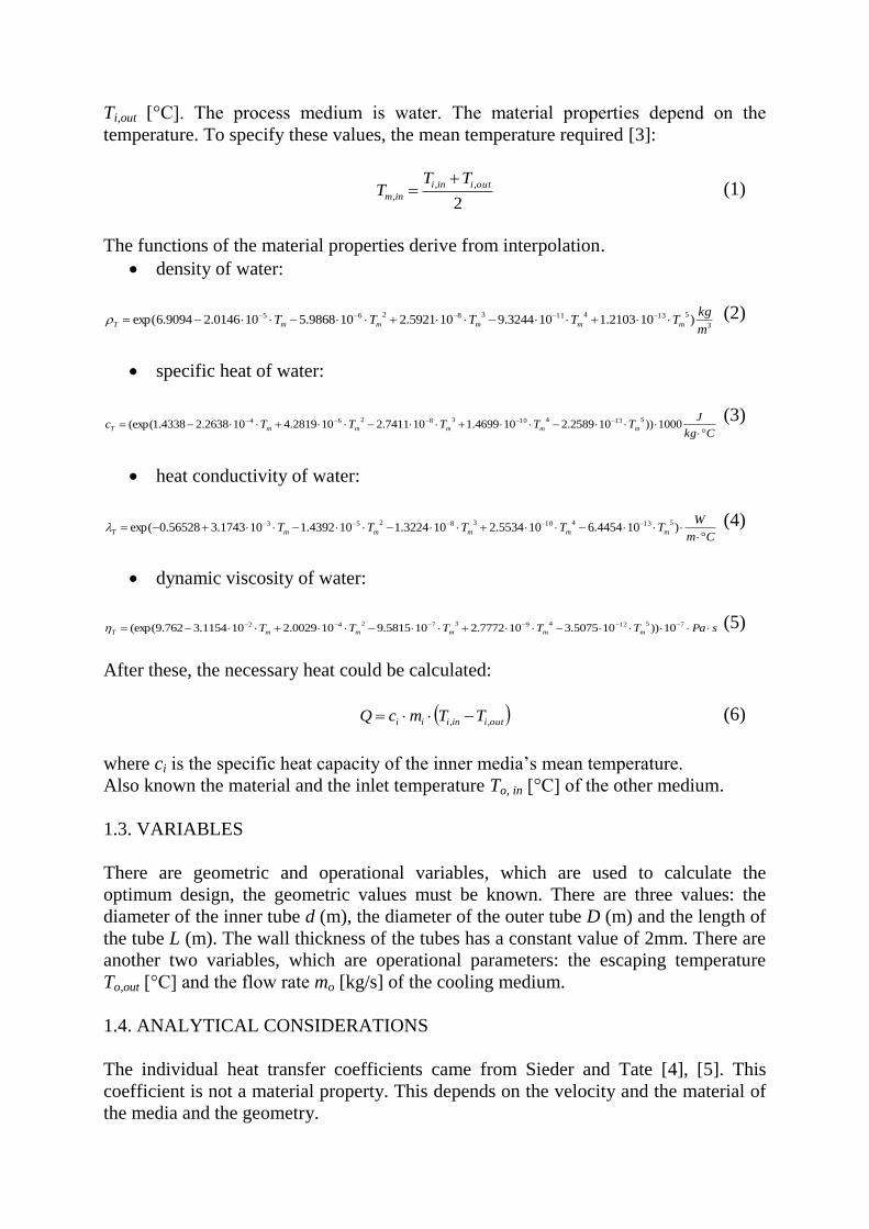
Ti,out [°C]. The process medium is water. The material properties depend on the
temperature. To specify these values, the mean temperature required [3]:
2
,,
,
outiini
inm
TTT
(1)
The functions of the material properties derive from interpolation.
density of water:
3
51341138265 )102103.1103244.9105921.2109868.5100146.29094.6exp(m
kgTTTTT mmmmmT (2)
specific heat of water:
Ckg
JTTTTTc mmmmmT
1000))102589.2104699.1107411.2102819.4102638.24338.1(exp(
51341038264 (3)
heat conductivity of water:
Cm
WTTTTT mmmmmT
)104454.6105534.2103224.1104392.1101743.356528.0exp(
51341038253 (4)
dynamic viscosity of water:
sPaTTTTT mmmmmT 75124937242 10))105075.3107772.2105815.9100029.2101154.3762.9(exp( (5)
After these, the necessary heat could be calculated:
outiiniii TTmcQ ,, (6)
where ci is the specific heat capacity of the inner media’s mean temperature.
Also known the material and the inlet temperature To, in [°C] of the other medium.
1.3. VARIABLES
There are geometric and operational variables, which are used to calculate the
optimum design, the geometric values must be known. There are three values: the
diameter of the inner tube d (m), the diameter of the outer tube D (m) and the length of
the tube L (m). The wall thickness of the tubes has a constant value of 2mm. There are
another two variables, which are operational parameters: the escaping temperature
To,out [°C] and the flow rate mo [kg/s] of the cooling medium.
1.4. ANALYTICAL CONSIDERATIONS
The individual heat transfer coefficients came from Sieder and Tate [4], [5]. This
coefficient is not a material property. This depends on the velocity and the material of
the media and the geometry.
Page 4
d
iiii
3
18.0
PrRe023.0 (7)
The specific geometry is the diameter of the inner tube (d). The Reynolds number
consist the velocity, which can be calculated from the mass flow rate with the help of
flow cross-section.
2
4
d
mv i
i (8)
The individual heat transfer coefficient is similar to the outer side, just the specific
geometry differs, and the material properties must be calculated to the mean
temperature of the cooling medium.
2
,,
,
outoino
outm
TTT
(9)
dD
oooo
3
18.0
PrRe023.0 (10)
In this case the cooling medium flows in the annulus, so the velocity is:
44
22
dD
mv o
o (11)
At this point the heat transfer features, the geometry and the temperatures are known,
so the performance of the device can be calculated. The heat transfer coefficient
depends on the convection of the inner tube both side and the conduction in the wall.
osteel
steel
i
sk
11
1
(12)
The heat transfer area depends on the diameter and the length of the inner tube. It does
not depend on the diameter of the outer pipe, because the two process fluids contact
each other at the surface of the inner pipe. So, the bigger outer pipe does not increase
the heat transfer area. Increasing of the outer pipe diameter causes higher material cost
and lower heat convection performance.
LdA (13)
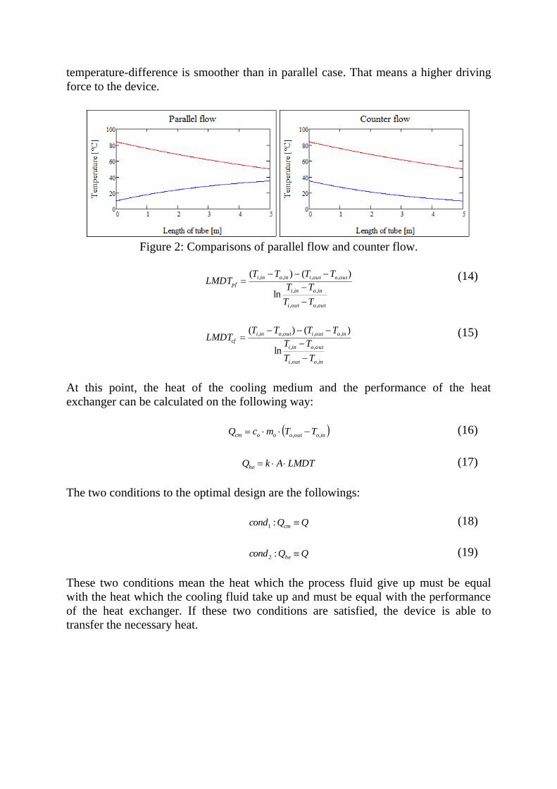
At the beginning of the calculation must be decided the flow paths. In this case that
will be clear parallel flow or clear counter flow. In case of counter flow the average
Page 5
temperature-difference is smoother than in parallel case. That means a higher driving
force to the device.
Figure 2: Comparisons of parallel flow and counter flow.
outoouti
inoini
outooutiinoini
pf
TT
TT
TTTTLMDT
,,
,,
,,,,
ln
)()(
(14)
inoouti
outoini
inooutioutoini
cf
TT
TT
TTTTLMDT
,,
,,
,,,,
ln
)()(
(15)
At this point, the heat of the cooling medium and the performance of the heat
exchanger can be calculated on the following way:
inooutooocm TTmcQ ,, (16)
LMDTAkQhe (17)
The two conditions to the optimal design are the followings:
QQcond cm :1 (18)
QQcond he :2 (19)
These two conditions mean the heat which the process fluid give up must be equal
with the heat which the cooling fluid take up and must be equal with the performance
of the heat exchanger. If these two conditions are satisfied, the device is able to
transfer the necessary heat.
Page 6
2. OBJECTIVE FUNCTION
2.1. MATERIAL COST
The material cost is directly proportional with the mass of the tubes. The most
common used structural materials are the carbon steel, austenitic steel, aluminum and
copper. The corrosion properties of the process fluids define the type of the material.
Over this corrosion property, these metals have different heat conductivity and
different cost. So, the material selection is part of the initial parameters. During the
optimization, the material grade is constant.
LDsDdsd
scC matMm
44
)2(
44
)2( 2222 (20)
In this correlation, cM means a specific material cost [$/kg], ρm is the density of the
structural material [kg/m3] and s is wall thickness [mm] (this is constant).
2.2. OPERATIONAL COST
Beside the material cost, another important factor is the operational cost. Flow created
frictional forces, which will restrain the flow. Due to this fact, between the two ends of
the pipe will be a pressure difference. This pressure drop (Δp) is a loss in the system. If
bigger the pressure drop, higher the operational cost and to complement this energy, a
pump must be used. The pressure drop depends on a friction factor, the velocity and
density of the stream and the geometric sizes of the pipe.
The friction factor came from the Blasius equation:
,Re
316.025.0
i
if (21)
to the inner tube and
,Re
316.025.0
o
of (22)
to the outer tube. The pressure drop in the straight line is the following:
,2
2
iiii
v
d
Lfp
(23)
.2
2
oooo
v
dD
Lfp
(24)
It is clearly seen, that the value of the pressure drop depends on the variables, just as
the conditions. That means there are geometric and operating parameters, where the
conditions are satisfied and the objective has a minimum value.
Page 7
Unfortunately to build a very long heat exchanger is not possibly, so a maximum
length must be defined. The longer the length, the more the necessary elbows. This
study maximized the length at the value of 3meters. So, the numbers of elbows are
rounding down the ratio of the length and the maximized length.
roundingm
Lne
3 (25)
The pressure drop in this elbows is the function of the velocity, the density and a
coefficient, which came from Fábry: [6]
2
12.12.02
,ii
eei
vnp
and .
212.12.0
2
,oo
eeo
vnp
(26,27)
The total operation cost is the next:
).()( ,, eoo
o
oEeii
i
iEop pp
mcpp
mcC
(28)
where is cE is a specific operational cost ($/kWh). The total cost is the amount of the
material and operational costs:
opmtotal CCC . (29)
2.3. BOUNDARY CONDITIONS
The diameter of inner tube must be at least 25mm. Under this size, the inner velocity
will too big value, which occurs a fast erosion in the tube wall. Naturally, the outer
tube must be bigger diameter than the inner one. If these two diameters are close
together, the velocity in the annulus will be high, this could be also harmful.
The escaping temperature of the outer media must be a higher value than the entering
temperature. The flow rate and the tube length must be positive numbers.
3. DESIGN EXAMPLE
3.1. WATER AND WATER MEDIA, TECHNICAL FLUID IN THE INNER TUBE
A double pipe heat exchanger must be build, when the technical fluid is water, which
flows in the inner tube, the inlet flow rate is 2kg/s, the inlet temperature is 80°C and
the outlet temperature is 50°C. The cooling stream is water flows in the annulus and its
inlet temperature is 20°C. The media flow counter-current in the first case and parallel
current in the second case.
Table 1: Optimized values to a heat exchanger using water to water
Counter-current Parallel-current
Inner tube d 73.63mm 75,79mm
Page 8
Outer tube D 114.28mm 132,59mm
Mass flow mo 2.75 kg/s 4,41 kg/s
Outlet
temperature To,out 41.78 °C 33,61°C
Length L 29.99m 31,92m
Material cost Cm 681.56$ 802,57$
Operational cost Cop 297.07$ 341,28$
Total cost Ctotal 978.62$ 1143,86$
3.2. WATER AND WATER MEDIA, TECHNICAL FLUID IN THE ANNULUS
There is another optimization process, when the technical fluid flows in the annulus
instead of the inner tube. That means the boundary conditions are changed, which
occur different optimum point. The optimum points are calculated counter-current and
parallel-current.
Table 2: Optimized values to a water to water heat exchanger
Counter-current Parallel-current
Inner tube d 165.58mm 179.73mm
Outer tube D 186.57mm 199.79mm
Mass flow mo 12.34 kg/s 14.43 kg/s
Outlet
temperature To,out 24.86 °C 24.16°C
Length L 11.99m 11.47m
Material cost Cm 505.93$ 520.81$
Operational cost Cop 220.36$ 224.83$
Total cost Ctotal 726.29$ 745.64$
In Table 1 and Table 2 it can be seen, that the counter-current is better than parallel
current and the correct selection of the flow area effects the optimum point.
3.3. WATER AND ETHANOL MEDIA, TECHNICAL FLUID IN THE INNER
TUBE
Uncommon in industrial practice that water heat or cool other water stream. For
example, in a distillation ethanol stream must be cooled in a heat exchanger. In this
case, the material properties are changed. The properties of the ethanol can be
calculated as the water’s properties, just the polynomial coefficients are different.
Table 3: Polynomial coefficients to the material properties of ethanol a0 a1 a2 a3 a4 a5
ρ -0.1079 -7.7201·10-3
1.5906·10-4
-1.6139·10-6
7.1873·10-9
-1.2075·10-11
c 0.81763 2.6793·10-3
1.3888·10-5
-4.3856·10-11
4.4424·10-10
1.5104·10-12
λ -1.6976 -1.2503·10-3
7.5291·10-7
5.2361·10-8
-3.4986·10-10
6.4599·10-13
η 0.5894 -2.2540·10-2
1.0283·10-4
-8.8574·10-7
4.7884·10-9
-9.7493·10-12
Page 9
3
5
5
4
4
3
3
2
210)( )exp(m
kgTaTaTaTaTaa mmmmmethT (30)
Kkg
JTaTaTaTaTaac mmmmmethT
1000)exp(
5
5
4
4
3
3
2
210)( (31)
Km
WTaTaTaTaTaa mmmmmethT
)exp(
5
5
4
4
3
3
2
210)( (32)
sPaTaTaTaTaTaa mmmmmethT 35
5
4
4
3
3
2
210)( 10)exp( (33)
So, the initial conditions are the same as the 3.1. section, but the material of the fluid is
ethanol. After optimization, the results are the following:
Table 4: Optimized values to an ethanol to water heat exchanger, technical fluid in the
inner tube
Counter-current Parallel-current
Inner tube d 70.99mm 65.43mm
Outer tube D 111.24mm 121.63mm
Mass flow mo 2.25 kg/s 3.51 kg/s
Outlet
temperature To,out 38.07 °C 31.6°C
Length L 38.8m 44.99m
Material cost Cm 855.74$ 1017.78$
Operational cost Cop 371.69$ 459.59$
Total cost Ctotal 1227.73$ 1477.37$
If the ethanol stream pass into the annulus instead of the inner tube, the results:
Table 5: Optimized values to an ethanol to water heat exchanger, technical fluid in the
annulus
Counter-current Parallel-current
Inner tube d 232.15mm 247.67mm
Outer tube D 249.13mm 263.94mm
Mass flow mo 19.8 kg/s 22.35 kg/s
Outlet
temperature To,out 22.05 °C 21.82°C
Length L 10.67m 10.15m
Material cost Cm 613.35$ 619.81$
Operational cost Cop 275.12$ 277.95$
Total cost Ctotal 888.47$ 897.76$
It is true for this material-pair, that the counter-current is more favourable than the
parallel-current. From Table 1, 2, 4 and 5, the results show that we get a smaller
optimum value
Page 10
, if the technical stream flows in the annulus. Calculation shows The diameter of the
tubes getting bigger, but the length of the tubes getting smaller. The fluid velocities in
every case is lesser than 1 m/s. If the corrosion is negligible, worth to calculate the
performance at the case of the two possible ways.
4. COMPARISONS, INITIAL PARAMETER SENSIBILITY
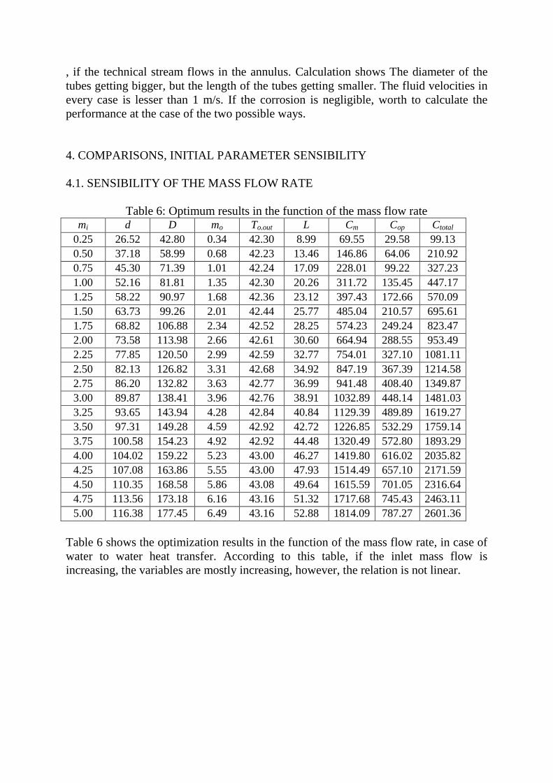
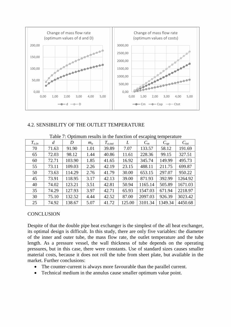
4.1. SENSIBILITY OF THE MASS FLOW RATE
Table 6: Optimum results in the function of the mass flow rate mi d D mo To.out L Cm Cop Ctotal
0.25 26.52 42.80 0.34 42.30 8.99 69.55 29.58 99.13
0.50 37.18 58.99 0.68 42.23 13.46 146.86 64.06 210.92
0.75 45.30 71.39 1.01 42.24 17.09 228.01 99.22 327.23
1.00 52.16 81.81 1.35 42.30 20.26 311.72 135.45 447.17
1.25 58.22 90.97 1.68 42.36 23.12 397.43 172.66 570.09
1.50 63.73 99.26 2.01 42.44 25.77 485.04 210.57 695.61
1.75 68.82 106.88 2.34 42.52 28.25 574.23 249.24 823.47
2.00 73.58 113.98 2.66 42.61 30.60 664.94 288.55 953.49
2.25 77.85 120.50 2.99 42.59 32.77 754.01 327.10 1081.11
2.50 82.13 126.82 3.31 42.68 34.92 847.19 367.39 1214.58
2.75 86.20 132.82 3.63 42.77 36.99 941.48 408.40 1349.87
3.00 89.87 138.41 3.96 42.76 38.91 1032.89 448.14 1481.03
3.25 93.65 143.94 4.28 42.84 40.84 1129.39 489.89 1619.27
3.50 97.31 149.28 4.59 42.92 42.72 1226.85 532.29 1759.14
3.75 100.58 154.23 4.92 42.92 44.48 1320.49 572.80 1893.29
4.00 104.02 159.22 5.23 43.00 46.27 1419.80 616.02 2035.82
4.25 107.08 163.86 5.55 43.00 47.93 1514.49 657.10 2171.59
4.50 110.35 168.58 5.86 43.08 49.64 1615.59 701.05 2316.64
4.75 113.56 173.18 6.16 43.16 51.32 1717.68 745.43 2463.11
5.00 116.38 177.45 6.49 43.16 52.88 1814.09 787.27 2601.36
Table 6 shows the optimization results in the function of the mass flow rate, in case of
water to water heat transfer. According to this table, if the inlet mass flow is
increasing, the variables are mostly increasing, however, the relation is not linear.
Page 11
4.2. SENSIBILITY OF THE OUTLET TEMPERATURE
Table 7: Optimum results in the function of escaping temperature
To.in d D mo To.out L Cm Cop Ctot
70 71.63 91.90 1.01 39.89 7.07 133.57 58.12 191.69
65 72.03 98.12 1.44 40.86 11.61 228.36 99.15 327.51
60 72.71 103.90 1.85 41.65 16.92 345.74 149.99 495.73
55 73.11 109.03 2.26 42.19 23.15 488.11 211.75 699.87
50 73.63 114.29 2.76 41.79 30.00 653.15 297.07 950.22
45 73.91 118.95 3.17 42.13 39.00 871.93 392.99 1264.92
40 74.02 123.21 3.51 42.81 50.94 1165.14 505.89 1671.03
35 74.29 127.93 3.97 42.71 65.93 1547.03 671.94 2218.97
30 75.10 132.52 4.44 42.52 87.00 2097.03 926.39 3023.42
25 74.92 138.67 5.07 41.72 125.00 3101.34 1349.34 4450.68
CONCLUSION
Despite of that the double pipe heat exchanger is the simplest of the all heat exchanger,
its optimal design is difficult. In this study, there are only five variables: the diameter
of the inner and outer tube, the mass flow rate, the outlet temperature and the tube
length. As a pressure vessel, the wall thickness of tube depends on the operating
pressures, but in this case, there were constants. Use of standard sizes causes smaller
material costs, because it does not roll the tube from sheet plate, but available in the
market. Further conclusions:
The counter-current is always more favourable than the parallel current.
Technical medium in the annulus cause smaller optimum value point.
0,00
50,00
100,00
150,00
200,00
0,00 1,00 2,00 3,00 4,00 5,00
Change of mass flow rate (optimum values of d and D)
d D
0,00
500,00
1000,00
1500,00
2000,00
2500,00
3000,00
0,00 1,00 2,00 3,00 4,00 5,00
Change of mass flow rate (optimum values of costs)
Cm Cop Ctot
Page 12
ACKNOWLEDGEMENT
The research was supported by the Hungarian Scientific Research Fund OTKA T
109860 project and the study was carried out as part of the EFOP-3.6.1-16-00011
“Younger and Renewing University – Innovative Knowledge City – institutional
development of the University of Miskolc aiming at intelligent specialisation” project
implemented in the framework of the Széchenyi 2020 program. The realization of this
project is supported by the European Union, co-financed by the European Social
Fund.”
REFERENCES
[1] R. L. Mohanty and S. Bashyam, “Numerical analysis of double pipe heat
exchanger using heat transfer augmentation techniques,” vol. 18, no. 124, pp.
337–348, 2015.
[2] R. Kareem, “Optimisation of Double Pipe Helical Tube Heat Exchanger and its
Comparison with Straight Double Tube Heat Exchanger,” J. Inst. Eng. Ser. C,
2016.
[3] M. Sheikholeslami and D. D. Ganji, “Fluid flow and heat transfer in an air-to-
water double-pipe heat exchanger,” pp. 1–12, 2015.
[4] E. N. Sieder and G. E. Tate, “Heat transfer and pressure drop of liquids in tube,”
Ind. Eng. Chem., vol. 28, no. 12, pp. 1429–1435, 1936.
[5] P. K. Swamee, N. Aggarwal, and V. Aggarwal, “Optimum design of double pipe
heat exchanger,” vol. 51, pp. 2260–2266, 2008.
[6] G. Fábry, Vegipari gépészek kézikönyve. 1987.