Alberto Di Matteo · Thomas Furtmüller ·Christoph Adam · Antonina Pirrotta
Optimal design of tuned liquid column dampers for seismicresponse control of base-isolated structuresThis paper is dedicated to the memory of Franz Ziegler
Abstract In this paper, the use of a tuned liquid column damper (TLCD) as a cost-effective means to controlthe seismic response of a base-isolated structure is studied. A straightforward direct approach for the optimaldesign of such a device is proposed, considering awhite noisemodel of the base excitation. On this base, a directoptimization procedure of the TLCDdesign parameters is performed and optimal design charts are presented asa ready-to-use practical design tool. Comparison with the optimal parameters obtained considering a classicaliterative statistical linearization technique proves the reliability of the proposed approach. The performance ofthe base-isolated TLCD-controlled structure is examined and compared with that of the simple base-isolatedone (without TLCD), using a set of 44 recorded ground motions as base excitation. Theoretical and numericalresults show that the TLCD is rather effective in reducing the response of base-isolated structures under strongearthquakes. Therefore, considering its advantageous characteristics and its overall beneficial effects, TLCDscan be considered as practical and appealing means to control the seismic response of base-isolated structures.
1 Introduction
Seismic base-isolation is one of the most effective and widely used means for protection of relatively stiffstructures against earthquake excitation. Through a base-isolation subsystem, the structure is virtually decou-pled from the ground. Decoupling is achieved by inserting a layer of low horizontal and high vertical stiffnessbetween the structure and its foundation, shifting the fundamental natural frequency of the entire structuralsystem away from the range of frequencies that dominate the earthquake excitation [16]. In this manner, thestructure on the base-isolation system tends to behave like a rigid body, since the majority of the displacement
A. Di Matteo · A. PirrottaDipartimento di Ingegneria Civile, Ambientale, Aerospaziale, dei Materiali (DICAM), Università degli Studi di Palermo,90128 Palermo, ItalyE-mail: [email protected]
T. Furtmüller · C. Adam (B)Unit of Applied Mechanics, University of Innsbruck, 6020 Innsbruck, AustriaE-mail: [email protected]
occurs within the base-isolation system itself. Hence, structure displacements and accelerations are greatlyreduced, while the base-isolation subsystem undergoes large, and sometimes undesirable, displacements.
Several research efforts have been focused on the reduction in this displacement demand of the base-isolation subsystem, resorting tomany different strategies.One commonway, for instance, consists in providingsupplemental damping to the isolation layer, which, however, may lead to an increase in the interstory driftsand accelerations of the main structure [17].
In this context, some researchers began to consider using passive vibration control devices, such as thewell-known tuned mass damper (TMD), to improve the performance of base-isolation systems. Specifically,initial studies can be found in [33] and [29], where the effect of the TMD on base-isolated structures and thechoice of the proper TMD parameters have been investigated. Further, in [22] it has been demonstrated that theTMD is more effective at reducing the structural response for low damping in the base-isolation subsystem,and in general TMDs can lead to better control performance than providing supplemental damping to theisolation layer [21], since small interstory drifts typical of base-isolated structures are preserved, while thedisplacement demand of the base-isolation subsystem is reduced [2]. As far as the optimal choice of the TMDparameters attached to base-isolation subsystems is concerned, some analyses in the frequency domain arepresented in [33], while in [27] optimal TMD design parameters are determined considering the case of a whitenoise ground excitation. More recently, in [31] the optimization of a non-traditional TMD, with minor strokelength demand, is discussed. Finally it is worth noting that, apart from the case of a ground excitation, in [15]the performance of a base-isolated structure equipped with a TMD device has been studied considering a windtype of excitation, demonstrating that attaching a TMD at the roof or base can reduce the structural responsesignificantly.
In all the previous investigations, only the case of TMD devices connected to the base-isolated structureshas been analyzed. In this regard, there are very few studies in which other passive control devices have beenconsidered for reducing the displacement demand of base-isolated structures. Specifically, in [20] the case ofa tuned liquid damper (TLD) device has been examined for wind induced motion of base-isolated buildings.
One interesting control device, which in recent years has attracted the attention of an increasing numberof researchers, is the so-called tuned liquid column damper (TLCD). The TLCD is a passive vibration controldevice that dissipates structural vibrations through the motion of a liquid column inside U-shaped containers,based on the same mechanical principle as the TMD. The liquid column can freely flow inside the U-shapedcontainer, and the liquid surface in the two vertical columns of the container is under constant atmosphericpressure. In this manner, the natural frequency of oscillation of the liquid theoretically depends only on thetotal length of the liquid column [1,13], thus making TLCDs particularly suitable for systems characterizedby a predominant first mode with very low fundamental natural frequency, as in the case of base-isolatedstructures.
To overcome the limitation of applicability to structures with very low fundamental frequencies, Zieglerand coworkers (see, e.g., [14,24,25,35]) have developed the highly innovative tuned liquid column gas damper(TLCGD), where in contrast to the TLCD both ends of the U-shaped tube are sealed, and thus, the gas-springeffect is activated [11,35], pushing the frequency range applicability of such devices up to 5 Hz [14]. Activecontrol of pressure input into the gas volume (ATLCGD) even allows to reduce the transient structural vibrationpeaks, observed in the initial period of the strongmotion phase of earthquakes [13,14]. Recently, several generalon-off damping controller for a semi-active TLCD has been implemented [19]. In [35], Ziegler proposed anovel TLCD for mitigating vertical vibrations. Hochrainer and Ziegler [14] used for the first time a TLCDto control a base-isolated five-story generic frame structure. More recently, Khalid and Ziegler [18] studieda novel base-isolation system with effective damping supplied by a TLCGD. For a complete overview onthe application of the TLCD and its passive and active variants in buildings, bridges and dams, the reader isreferred to Hochrainer and Ziegler [12].
The TLCD is generally modeled as a single-degree-of-freedom (SDOF) system rigidly connected to avibrating structure [6,8,13], and its effectiveness depends on proper tuning of the natural frequency anddamping ratio, such as in a TMD. However, unlike the traditional TMD, the TLCD response is nonlinear [5,9]and the optimal damping parameters cannot be established a priori unless the forcing magnitude is known andnumerical optimization methods are required (see [7] and references therein).
Due to some of their beneficial characteristics (such as low cost, easy implementation, lack of requiredmaintenance, no need to add mass to the structure when using the liquid as water supply), TLCD representsnow an attractive alternative for vibrations mitigation. Readers may refer to Ziegler [34] for a detailed analysison the beneficial features of TLCDs among different types of passive vibration control systems.
Optimal design of tuned liquid column dampers in base-isolated structures 439
Based on the pioneering applications of Ziegler [14,18], and in the context of taking into account theseattractive characteristics, in this paper the control performance of a TLCD on the seismic response of abase-isolated structure is investigated. Once the nonlinear equations of motion of a TLCD-controlled multi-degree-of-freedom (MDOF) base-isolated structure are derived, the classical statistical linearization technique(SLT) is applied to analyze the statistics of the response in case of a Gaussian white noise ground excitation,and comparison with Monte Carlo simulation data is used to prove the reliability of the results. Since SLTrequires several computationally expensive numerical iterations, a straightforward procedure is proposed thatallows for the direct evaluation of the equivalent linear system parameters and corresponding steady-stateresponse variances, under some reasonable assumptions regarding base-isolated structures. In order to provethe reliability of the proposed approach, comparisonwith the SLT is provided, showing a satisfactory agreementbetween the two approaches, even when the aforementioned assumptions are removed. Further, taking fulladvantages of this proposed direct evaluation of the equivalent linear system parameters, a direct optimizationprocedure of the TLCD design parameters is performed, aiming at maximally control the seismic responseof the base-isolated structure. Optimal design charts are introduced as a ready-to-use practical design tool.Comparison with the optimal parameters obtained by a rather elaborate numerical optimization procedure,based on the classical iterative SLT, is carried out leading to very small discrepancies especially in terms ofcontrol performances. It isworthmentioning that a significant reduction in computational effort is achievedwiththe proposed straightforward approach. Finally, to show the influence of the non-stationary nature of real groundmotions, the control performances of the TLCD device directly connected to the base-isolation subsystem areexamined employing time-history analyses using the 44 recorded ground motions of the FEMA P-695 far-field(FEMA P-695-FF) set described in [10]. Specifically, a 20-story benchmark base-isolated building, used in[33], has been taken into account. It is shown that the TLCD device leads to a 16% reduction in the median ofthe relative peak base-isolation subsystem displacement, compared to the case of the base-isolated structurewithout TLCD.
2 Problem formulation
Let the equations of motion of a planar frame with lumped mass and n degrees-of-freedom (main structure)subjected to a horizontal earthquake ground acceleration xg (t) be given in classical matrix form as
Mx (t) + Cx (t) + Kx (t) = −Mrxg (t) , (1)
where M, C and K are the n × n mass, damping and stiffness matrix, respectively, of the structure, x is thevector containing the nodal deformations of the structure, r is the location vector and a dot over a variablestands for derivation with respect to time t . Equation (1) can be rewritten as
Mi xi (t) +n∑
j=1
Ci, j x j (t) +n∑
j=1
Ki, j x j (t) = −Mi xg (t) (i = 1, . . . ,n) , (2)
where the terms Mi , Ci, j and Ki, j in Eq. (2) correspond to the entries of the matricesM, C andK, while xi isthe i th nodal deformation of the structure relative to the ground.
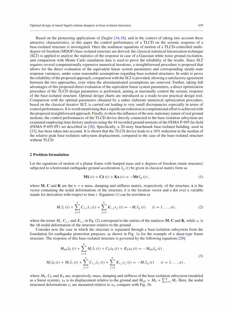
Consider now the case in which the structure is separated through a base-isolation subsystem from thefoundation for earthquake protection purposes, as shown in Fig. 1a for the example of a shear-type framestructure. The response of this base-isolated structure is governed by the following equations [29]:
Mtot xb (t) +n∑
i=1
Mi xi (t) + Cbxb (t) + Kbxb (t) = −Mtot xg (t) ,
Mi xb (t) + Mi xi (t) +n∑
j=1
Ci, j x j (t) +n∑
j=1
Ki, j x j (t) = −Mi xg (t) (i = 1, . . . ,n) ,
(3)
where Mb, Cb and Kb are, respectively, mass, damping and stiffness of the base-isolation subsystem (modeledas a linear system), xb is its displacement relative to the ground and Mtot = Mb + ∑n
i=1 Mi . Here, the nodalstructural deformations xi are measured relative to xb, compare with Fig. 1b.
440 A. Di Matteo et al.
(a)
(c)
x1(t)
Mn
x2(t)
xn(t)
xb(t)xg(t)
main structureM2
M1
base-isolation subsystem
Mb
x1(t)
xb(t)xg(t)
M1
y(t)
Mb
x1(t)
Mn
x2(t)
xn(t)
xb(t)xg(t)
TLCD device
M2
M1
y(t)LH
LV
(b)
MbKb, Cb
Fig. 1 Base-isolated structures: a MDOF shear-type frame without TLCD; b hybrid-controlled MDOF shear-type frame withTLCD; c hybrid-controlled SDOF shear frame with TLCD
When dealing with a SDOF main structure (i.e., n = 1), Eq. (3) reverts to
where μ1 = M1/Mtot, ωb = √Kb/Mtot and ζb = Cb/(2Mtotωb) are the natural frequency and damping
ratio of the base-isolation system, respectively, while ω1 = √K1/M1 and ζ1 = C1/(2M1ω1) are the natural
frequency and damping ratio of the SDOF main structure.Aiming at reducing the displacement demand xb of the isolation subsystem, consider now the case of the
above-described base-isolatedmulti-story structure inwhich a TLCDdevicewith constant tubular cross sectionis rigidly attached to the base plate of the base-isolation subsystem, as shown in Fig. 1b. Denoting with g thegravitational acceleration, Lv and Lh the vertical and horizontal liquid length, respectively, L = Lh + 2Lv
the total length of the liquid inside the TLCD, the corresponding equations of motion of this n + 2 degrees-of-freedom system can be written as
(Mtot + ml) xb (t) + mh y +n∑
i=1
Mi xi (t) + Cbxb (t) + Kbxb (t) = − (Mtot + ml) xg (t) ,
mhxb (t) + ml y (t) + ml
2Lξ |y (t)| y (t) + 2
ml
Lg y (t) = −mhxg (t) , (5)
Mi xb (t) + Mi xi (t) +n∑
j=1
Ci, j x j (t) +n∑
j=1
Ki, j x j (t) = −Mi xg (t) (i = 1, . . . ,n) ,
where ml is the total liquid mass inside the TLCD device, mh = αml is the horizontal liquid mass, beingα = Lh/L the so-called length ratio, y(t) is the displacement of the liquid surface and ξ is the head losscoefficient. Note that Eq. (5) represents a set of n + 2 differential equations, the second of which is nonlinear.Specifically, the nonlinear term is generally used to model head losses caused by the presence of an orificeinside the TLCD and viscous interaction between the liquid and rigid container wall [6].
For an SDOF main structure (n = 1) as depicted in Fig. 1c, the equations of motion (5) are particularizedas
where μl = ml/Mtot is the liquid mass ratio and ωl = √2g/L is the natural frequency of oscillation of the
liquid column inside the TLCD [13]. Since the damping term in Eq. (6b) is nonlinear, even assuming thatthe base-isolation subsystem and the main structure behave linearly, the whole system experiences inherentnonlinear properties. Therefore, some difficulties may arise for the optimal design of the damper device inorder to obtain the maximum reduction in the displacement demand of the isolation subsystem.
Optimal design of tuned liquid column dampers in base-isolated structures 441
In the following section, a procedure based on statistical linearization will be introduced to overcome thesedifficulties.
2.1 Statistical linearization of base-isolated structure equipped with TLCD
Suppose that the latter base-isolated SDOF structure equipped with a TLCD (Fig. 1c) is driven by random baseexcitation, such as earthquake ground accelerations, that can be modeled as a zero-mean Gaussian white noiseprocess. It follows that the displacements of the liquid column and the base-isolation subsystem, nodal structuraldeformations and their derivatives are stochastic processes too (denoted by capital letters, as customary).Moreover, due to the presence of the nonlinear damping term, responses are non-Gaussian processes.
However, taking full advantage of the powerful tool of the Statistical Linearization Technique (SLT), theoriginal nonlinear system (6) can be replaced by a linear equivalent one as
where ζl is the equivalent damping ratio of the TLCD, obtained by minimizing the mean square with respectto ξ . Specifically, following the analysis in [4,26], the expression for the equivalent damping ratio becomes
ζl = ξ
2L ωl
√2
πσY , (8)
where σY is the standard deviation of the velocity of the liquid column. As shown in [4], the application ofEq. (8) for design purposes is not straightforward since σY is still unknown and implicitly depends on theequivalent damping ratio ζl . Therefore, generally an iterative procedure is necessary. Specifically, firstly thestandard deviation of the liquid column velocity σY is evaluated by fixing an arbitrary value of ζl , as
σ 2Y
=∞∫
0
ω2|HY (ω)|2G0 dω, (9)
in which HY (ω) is the liquid column displacement transfer function of the equivalent linear system (7) (seeAppendix A for further details) andG0 is the one-sided power spectral density (PSD) of the white noise groundexcitation. Further, substituting σY evaluated by Eq. (9) into Eq. (8) yields a new value of ζl . This procedureis repeated iteratively until no significant differences on ζl emerge in two consecutive iterations.
Clearly, once convergence is reached, the complete statistics of the response processes can be computed.In particular, defining Hb (ω) as the base-isolation subsystem displacement transfer function and HX1 (ω) themain structure nodal deformation transfer function of the equivalent linear system (7) (see Appendix A fordetails), response variances are obtained as
σ 2Xb
=∞∫
0
|Hb (ω)|2G0 dω, σ 2X1
=∞∫
0
∣∣HX1 (ω)∣∣2G0 dω, σ 2
Y =∞∫
0
|HY (ω)|2G0 dω. (10)
It should be noted that closed-form expression for these transfer functions can be easily computed, asreported in Appendix A. In this manner, all the response statistics can be immediately determined numericallysolving Eq. (10).
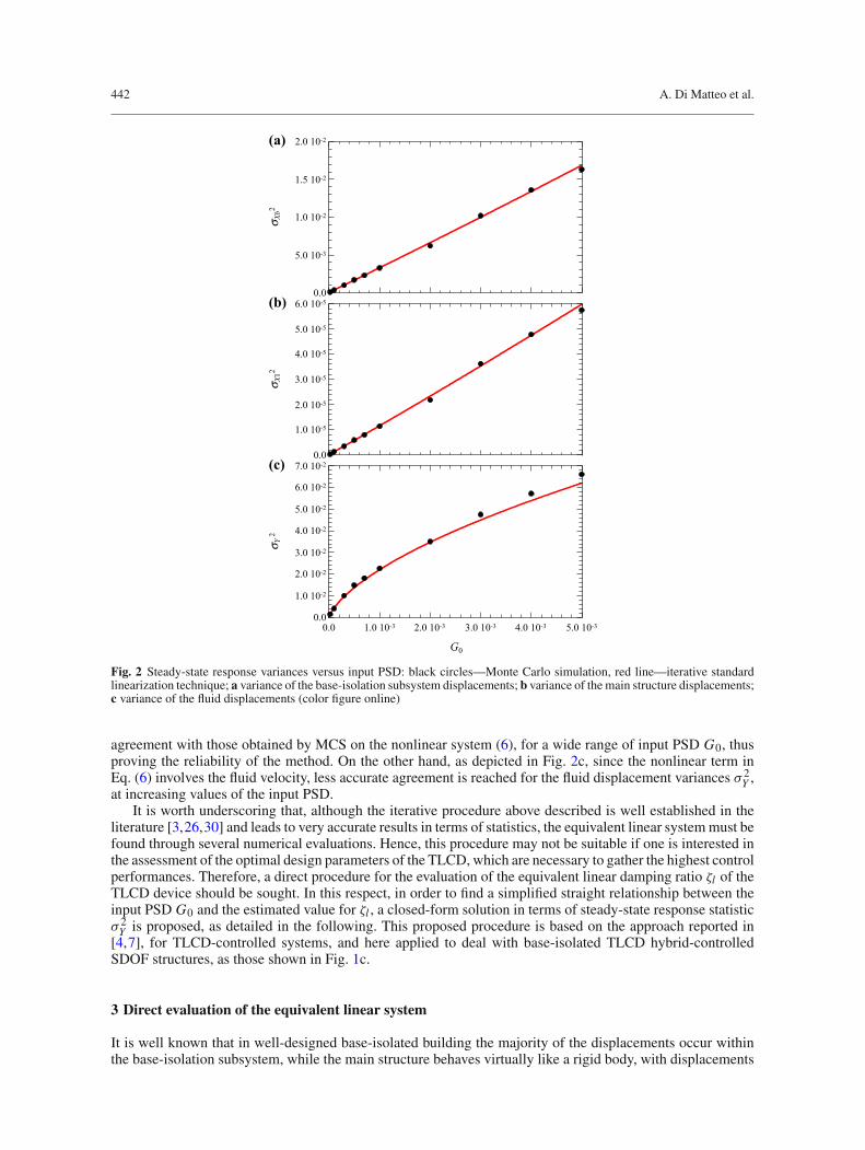
In order to demonstrate the accuracy of the above-described iterative SLT, Fig. 2 shows the response steady-state variances of the original nonlinear equations of motion, Eq. (6), additionally to variances computed viaEq. (10) through the iterative procedure, for different values of the input PSD G0. Note that statistics of theoriginal nonlinear system (6) have been evaluated through a Monte Carlo simulation (MCS) procedure, usingfor each analysis 2000 samples of ground accelerations and directly integrating the equations of motion. Inthis respect, parameters similar to those used in [31] have been here adopted for the numerical simulations.Specifically: ωb = π/2, ζb = 0.05, μ1 = 0.95, ω1 = 4ωb, ζ1 = 0.02, μl = 0.05, α = 0.6, ωl = 0.98ωb andξ = 10. As it can be observed in this figure, base-isolation subsystem displacement variance σ 2
Xb(Fig. 2a)
and main structure displacement variance σ 2X1
(Fig. 2b), predicted with the iterative SLT, are in very good
442 A. Di Matteo et al.
0.0
5.0 10-3
1.0 10-2
1.5 10-2
2.0 10-2
σ Xb2
(a)
0.0
1.0 10-5
2.0 10-5
3.0 10-5
4.0 10-5
5.0 10-5
6.0 10-5
σ X12
(b)
0.0
1.0 10-2
2.0 10-2
3.0 10-2
4.0 10-2
5.0 10-2
6.0 10-2
7.0 10-2
0.0 1.0 10-3 2.0 10-3 3.0 10-3 4.0 10-3 5.0 10-3
σ Y 2
G0
(c)
Fig. 2 Steady-state response variances versus input PSD: black circles—Monte Carlo simulation, red line—iterative standardlinearization technique; a variance of the base-isolation subsystem displacements; b variance of the main structure displacements;c variance of the fluid displacements (color figure online)
agreement with those obtained by MCS on the nonlinear system (6), for a wide range of input PSD G0, thusproving the reliability of the method. On the other hand, as depicted in Fig. 2c, since the nonlinear term inEq. (6) involves the fluid velocity, less accurate agreement is reached for the fluid displacement variances σ 2
Y ,at increasing values of the input PSD.
It is worth underscoring that, although the iterative procedure above described is well established in theliterature [3,26,30] and leads to very accurate results in terms of statistics, the equivalent linear systemmust befound through several numerical evaluations. Hence, this procedure may not be suitable if one is interested inthe assessment of the optimal design parameters of the TLCD, which are necessary to gather the highest controlperformances. Therefore, a direct procedure for the evaluation of the equivalent linear damping ratio ζl of theTLCD device should be sought. In this respect, in order to find a simplified straight relationship between theinput PSD G0 and the estimated value for ζl , a closed-form solution in terms of steady-state response statisticσ 2Y is proposed, as detailed in the following. This proposed procedure is based on the approach reported in
[4,7], for TLCD-controlled systems, and here applied to deal with base-isolated TLCD hybrid-controlledSDOF structures, as those shown in Fig. 1c.
3 Direct evaluation of the equivalent linear system
It is well known that in well-designed base-isolated building the majority of the displacements occur withinthe base-isolation subsystem, while the main structure behaves virtually like a rigid body, with displacements
Optimal design of tuned liquid column dampers in base-isolated structures 443
xb(t)xg(t)
Mtot
y(t)
Kb, Cb
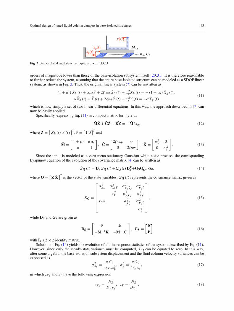
Fig. 3 Base-isolated rigid structure equipped with TLCD
orders of magnitude lower than those of the base-isolation subsystem itself [20,31]. It is therefore reasonableto further reduce the system, assuming that the entire base-isolated structure can be modeled as a SDOF linearsystem, as shown in Fig. 3. Thus, the original linear system (7) can be rewritten as
α Xb (t) + Y (t) + 2ζlωl Y (t) + ω2l Y (t) = −α Xg (t) ,
(11)
which is now simply a set of two linear differential equations. In this way, the approach described in [7] cannow be easily applied.
Specifically, expressing Eq. (11) in compact matrix form yields
MZ + CZ + KZ = −Mrxg, (12)
where Z = [Xb (t) Y (t)
]T, r = [1 0
]T and
M =[1 + μl αμl
α 1
], C =
[2ζbωb 0
0 2ζlωl
], K =
[ω2b 0
0 ω2l
]. (13)
Since the input is modeled as a zero-mean stationary Gaussian white noise process, the correspondingLyapunov equation of the evolution of the covariance matrix [4] can be written as
ΣQ (t) = DSΣQ (t)+ΣQ (t)DTs +GSGT
SπG0, (14)
where Q = [Z Z
]Tis the vector of the state variables, ΣQ (t) represents the covariance matrix given as
ΣQ =
⎡
⎢⎢⎢⎢⎢⎢⎣
σ 2Xb
σ 2XbY
σ 2Xb Xb
σ 2XbY
σ 2Y σ 2
Y Xbσ 2Y Y
sym σ 2X2b
σ 2XbY
σ 2Y
⎤
⎥⎥⎥⎥⎥⎥⎦, (15)
while DS and GS are given as
DS =[
0 I2
−M−1K −M−1C
], GS =
[0
r
](16)
with I2 a 2 × 2 identity matrix.Solution of Eq. (14) yields the evolution of all the response statistics of the system described by Eq. (11).
However, since only the steady-state variance must be computed, ΣQ can be equated to zero. In this way,after some algebra, the base-isolation subsystem displacement and the fluid column velocity variances can beexpressed as
σ 2Xb
= πG0
4zXbω3b
, σ 2Y
= πG0
4zYωl, (17)
in which zXb and zY have the following expression
zXb = NZ
DZXb
, zY = NZ
DZY, (18)
444 A. Di Matteo et al.
where
NZ = ζbζl + ζ 22
(4ζ 2
b + α2μl)ν + 2ζbζl
[2ζ 2
b + α2μl + (2ζ 2
l − 1)(1 + μl)
]ν2
+ ζ 2b
[α2μl + 4ζ 2
l (1 + μl)]ν3 + ζbζl(1 + μl)
2ν4,
DZXb = ζl(1 + μl − α2μl
)2
+ ζb[α4μ2
l + 4ζ 2l (1 + μl)
2] ν + ζl(1 + μl)2 [4ζ 2
b + 3α2μl + (4ζ 2
l − 2)(1 + μl)
]ν2
+ ζb(1 + μl)2 [
α2μl + 4ζ 2l (1 + μl)
]ν3 + ζl(1 + μl)
4ν4,
DZY = α2 [ζb + ζl
(1 + μl + 4ζ 2
b
)ν + 4ζ 3
b ν2],
(19)
and the so-called frequency tuning ratio ν = ωl/ωb has been introduced.By application of the procedure described in [4,7], in order to obtain a less cumbersome expression for the
fluid velocity variance, Eq. (19b) can be expanded in Taylor’s series with respect to ζl , retaining only the firsttwo terms of the expansion. Further, assuming that higher powers of ζb can be neglected
(ζ 2b = ζ 3
b ≈ 0), and
considering that generally ν ≈ 1, yieldszY ≈ (ζb + γ ζl) μl , (20)
where γ = 1− μl + μl/α2. Substitution of Eq. (20) into Eq. (17b) leads to an approximate expression for the
fluid velocity variance,
σ 2Y
= πG0
4 (ζb + γ ζl) μlωl. (21)
Finally, recalling Eq. (8), a direct relationship that provides the equivalent damping ratio ζl as a function ofthe input PSD G0 can be obtained as
ζ 2l (ζb + γ ζl) = ξ2G0
8L2 μl νω3b
, (22)
in which ωl has been replaced by the term νωb. This third order algebraic equation, which can be solved eithernumerically or in closed form, admits only one real solution in the parameters range of practical applications[4]. Therefore, if the base-isolation subsystem and TLCD parameters are known, Eq. (22) can be directlyused to evaluate ζl instead of applying the computationally more expensive iterative SLT procedure previouslydescribed.
On the other hand, recalling that ω2l = 2g/L [34], an expression relating the head loss coefficient ξ to the
equivalent damping ratio ζl can be obtained recasting Eq. (22) as
ξ = ξ0 (ν, ζl)√G0ωb
, (23)
where
ξ0 (ν, ζl) = 4gζl
√2μl (ζb + γ ζl)
ν. (24)
Note that Eqs. (23) and (24) are rather useful for a straightforward evaluation of the optimal TLCD designparameters, as it will be shown in the following.
3.1 Investigation on parameter sensitivity
In order to prove the reliability of the proposed direct approach for the evaluation of equivalent TLCD dampingparameter ζl , it will be shown how the variation of the involved parameters affects the proposed formulation.To aim at this objective, a reference set of parameters, used also in [31], has been selected, and in turn one ofthem has been varied in a wide range of values. Specifically, the following reference set of parameters is used:ωb = π/2, ζb = 0.05, μ1 = 0.95, ω1 = 4ωb, ζ1 = 0.02, μl = 0.05, α = 0.6, ξ = 10, and G0 = 5 × 10⁻⁴.
In the followingfigures, results in termsof normalized base-isolation displacement variance εXb = σ 2Xb
/σ 2X0
are displayed, being σ 2X0
the base-isolation displacement variance of the system without TLCD (see Eq. (4)).In particular, results obtained by the iterative SLT previously described (symbols) are compared with thoseobtained by the proposed direct approach (solid lines), for tuning ratio ν = ωl/ωb ranging from 0.8 to 1.2.
Optimal design of tuned liquid column dampers in base-isolated structures 445
0.2
0.4
0.6
0.8
1.0
1.2
ε Xb
(a)
μl = 0.07
μl = 0.05
μl = 0.03
μl = 0.10
0.2
0.4
0.6
0.8
1.0
1.2
ε Xb
(b)
α = 0.5α = 0.6α = 0.7α = 0.8
0.2
0.4
0.6
0.8
1.0
1.2
0.8 0.9 1.0 1.1 1.2
ε Xb
ν
(c)
ξ = 5
ξ = 10
ξ = 20
ξ = 30
Fig. 4 Normalized base-isolation subsystem displacement variance εXb as a function of frequency tuning ratio ν: markers—iterative standard linearization technique; lines—proposed direct approach; a variation of the mass ratio μl ; b variation of thelength ratio α; c variation of the head loss coefficient ξ
In Fig. 4, the effects of the variation of mass ratio μl , length ratio α and the head loss coefficient ξ on theproposed formulation are shown. As it can be observed, better agreement between iterative SLT and proposedapproach is attained for values of the tuning ratio ν lower than one, otherwise higher deviations can be detected.Further, as shown in Figs. 4a, b, the proposed procedure is slightly influenced by the variation of μl and α,while the accuracy of the results significantly decreases for higher values of ξ (see Fig. 4c).
In Fig. 5, similar results are reported for the variation of the base-isolation subsystem damping ratio ζb, themain structure damping ratio ζ1 and the input PSD G0. As for the previous cases, better agreement is obtainedfor values of the tuning ratio ν lower than one. In this case, however, the accuracy of the results decreases forhigher values of ζb (see Fig. 5a) and G0 (see Fig. 5c). On the other hand, as shown in Fig. 5b, no significantinfluence of the main structure damping ratio ζ1 on εXb can be observed.
Moreover, as shown inFig. 5a, the normalizedbase-isolation displacement variance εXb is greatly influencedby parameter ζb, meaning that highest control performance can be reached for low-damped base-isolationsubsystems, as expected.
It should be emphasized that, while the iterative SLT procedure takes into account the main structuredamping ratio ζ1, being developed on the complete equivalent linear system described by Eq. (7), the proposeddirect approach is developed on the reduced system in Eq. (11), which is therefore independent of ζ1. Thelatter is a remarkable result that makes the proposed procedure valid for hybrid-controlled MDOF structuresas well.
446 A. Di Matteo et al.
0.2
0.4
0.6
0.8
1.0
1.2
ε Xb
(a)ζb = 0.01ζb = 0.02ζb = 0.05
ζb = 0.07
0.2
0.4
0.6
0.8
1.0
1.2
ε Xb
(b)
ζl = 0.0002
ζl = 0.02
ζl = 0.002
ζl = 0.2
0.2
0.4
0.6
0.8
1.0
1.2
0.8 0.9 1.0 1.1 1.2
ε Xb
ν
(c)
G0 = 10-4
G0 = 5 10-4
G0 = 10-3
G0 = 5 10-3
Fig. 5 Normalized base-isolation displacement variance εXb as a function of frequency tuning ratio ν:Markers—iterative standardlinearization technique; Lines—proposed direct approach; a variation of the base-isolation damping ratio ζb; b variation of themain structure damping ratio ζ1; c variation of the input PSD G0
Finally, it should be underscored that, although some discrepancies between the iterative SLT and theproposed direct approach have been evidenced from the above analyses, the main purpose of the proposedprocedure is to quickly derive the optimal design parameters of the TLCD device, as it will be shown in thefollowing.
4 Optimal design parameters of TLCD systems
Once the expression directly linking ζl to the excitation PSD G0 has been introduced, the optimal designof TLCD devices for base-isolated structures can be effectively performed using the proposed approximateformulation. As customary, there is no need for an optimization procedure that includes all the TLCD involvedparameters, since μl and α are generally given by structural constraints. Therefore, the only parametersrequested are the frequency tuning ratio ν and the head loss coefficient ξ , or similarly the equivalent dampingratio ζl . Clearly, the real optimal parameters should be evaluated on the original nonlinear system (6), ormore easily on the equivalent linear equation (7), with ζl estimated through the iterative procedure previouslydescribed. It is worth noting that both these approaches are rather laborious and cannot be pursued in practicalapplication. In fact, the evaluation of the optimal parameters on the original nonlinear system (6) requires acomputationally demanding MCS, necessary to compute the statistics of the system for different values of
Optimal design of tuned liquid column dampers in base-isolated structures 447
Fig. 6 Sample of the smooth function φ (ν, ζl)
the design parameters, until a minimum of σ 2Xb
is reached for a certain set of values of (ν, ξ). Further, theevaluation of the optimal parameters on the equivalent linear system (7) requires a rather cumbersomenumericaloptimization,whichmust take into account the iterative procedure necessary to estimate the equivalent dampingratio ζl . On the other hand, Eq. (17a) directly expresses the base-isolation subsystem displacement variance σ 2
Xbof the reduced equivalent linear system in Eq. (11), as function of the input PSDG0 and the system parameters.Therefore, a more practical and straightforward approach is to look for the minimum of the smooth function
φ (ν, ζl) = 1
zXb
, (25)
which is independent of G0 and the natural base-isolation system frequency ωb. In Fig. 6, a sample of thefunction φ (ν, ζl) is shown.
Note that an analytical expression for theminimumof φ (ν, ζl) could be obtained, considering the nonlinearsystem of algebraic equations
∂φ (ν, ζl)
∂ν= 0 ,
∂φ (ν, ζl)
∂ζl= 0 (26)
However, this approach would lead to a rather complex expression, and thus, it is here omitted.A more simple procedure is to directly find numerically the minimum of φ (ν, ζl) in Eq. (25), through
numerical minimization procedure, such as those already implemented in many software packages (see, forinstance,FindMinimum inMathematica or fminsearch inMATLABenvironment). In thisway,Eq. (25) providesthe optimal design parameter values νopt and ζl,opt, which can be then used to compute the optimal head losscoefficient ξopt through Eq. (23) with ξ0
(νopt, ζl,opt
)given by Eq. (24).
As it will be shown in the following, application of the above- described procedure results in a significantreduction in computational effort, leading to optimized values that have almost the same performances as thoseobtained through the computationally demanding iterative procedure.
4.1 Investigation on the optimal design parameters
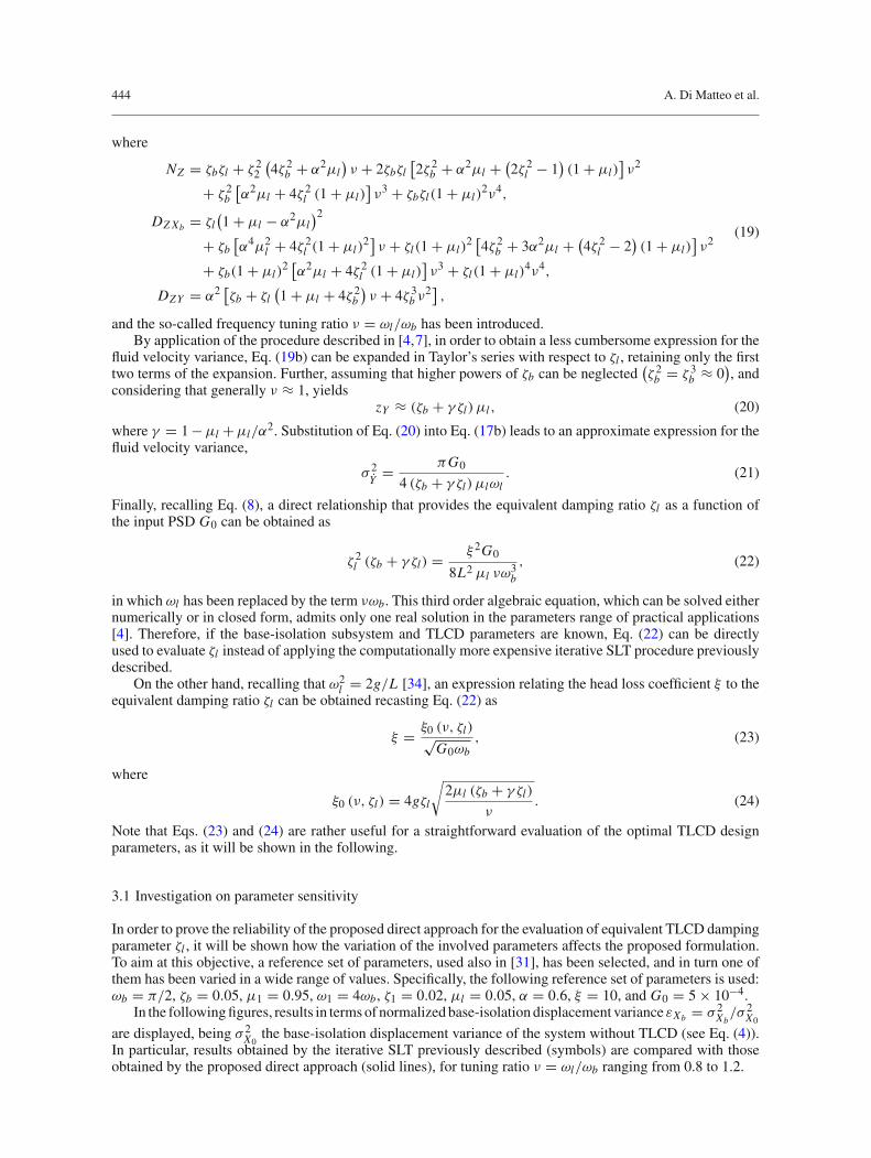
The main advantage of the proposed approach lies in the straightforward evaluation of the optimal values νoptand ζl,opt, which are independent of input PSD G0 and natural base-isolation frequency ωb. Therefore, thisprocedure can be used to create immediately useful design charts, in which optimal parameters can be directlydetermined. Specifically, the charts depicted in Fig. 7 show optimal values in terms of ξ0
(νopt, ζl,opt
)and νopt,
for different values of α. Further, several values of the base-isolation damping ratio ζb (black lines) and massratioμl (red lines) are depicted. The here proposed charts render the optimization procedure particularly easy.For instance, suppose that a length ratio α = 0.6 is taken into account, the damping ratio of the base-isolatedsystem is ζb = 0.02 and the mass ratio, given by structural constraints, isμl = 4%, thus identifying the pointAin Fig. 7b. This design chart directly provides the optimal parameters νopt = 0.964 and ξ0
(νopt, ζl,opt
) = 0.192,which can then be substituted into Eq. (23) to find the optimal head loss coefficient ξopt, once the input PSDG0 is known.
448 A. Di Matteo et al.
0.1
0.2
0.3
0.4
0.5
0.6
0.7
0.90 0.92 0.94 0.96 0.98
μl = 0.10
μl = 0.03
μl = 0.09
μl = 0.08
μl = 0.07
μl = 0.06μl = 0.05
μl = 0.04
ζb = 0.05
ζb = 0.01ζb = 0.001
ζb = 0.03
νopt
α = 0.6
(a)ξ 0
( νopt ,
ζl,o
pt)
A0.2
0.4
0.6
0.8
1.0
0.88 0.90 0.92 0.94 0.96 0.98
μl = 0.10
μl = 0.03
μl = 0.09
μl = 0.08
μl = 0.07
μl = 0.06
μl = 0.05
μl = 0.04
ζb = 0.05
ζb = 0.01ζb = 0.001
ζb = 0.03
νopt
α = 0.8
(b)
Fig. 7 Optimal design charts in terms of ξ0(νopt, ζl,opt
)and νopt; a α = 0.6; b α = 0.8
At this stage, it is worth noting that the above-described procedure can be still applied even for genericearthquake excitation, defined in the specific seismic code in terms of spectral acceleration response spectrum,as it will be shown in the following and further detailed in [7].
Finally, in order to show the accuracy of this proposed simplified approach, a comparison with the optimalvalues obtained through the iterative SLT has also been performed. In this respect, considering the previouslyintroduced reference set of parameters (see Sects. 3.1), which in turn have been varied in a wide range of values,the particle-swarm optimization (PSO) method [23] has been used to find those values of (ν, ξ) that minimizethe base-isolation displacement variance σ 2
Xbof the complete linear equations of motion (7). Note that, in this
way, for each iteration of the PSO optimization algorithm the iterative SLT must be applied to evaluate theequivalent linear damping ratio ζl , as previously discussed. Therefore, in this case, a rather elaborate numericalprocedure must be implemented.
In Table 1, the comparison among the optimal design parameters νopt and ζopt, obtained by the proposedsimplified approach, and those determined through the aforementioned iterative solution, is listed for variousvalues of the system parameters, together with the corresponding percentage differences. For the results ofthis table, the following reference set of values has been used: α = 0.06, μl = 0.05, ζb = 0.05, ζ1 = 0.01,G0 = 5 × 10⁻⁴.
Furthermore, Table 1 also provides the previously defined normalized base-isolation subsystem displace-ment variance εXb = σ 2
X0/σ 2
X0, where σ 2
X0is the base-isolation subsystem displacement variance of the system
without TLCD (see Eq. 4). Note that this parameter may also serve as a performance control index for thebase-isolated TLCD-controlled structure, since the lower εXb is, the more effective the TLCD has been. Asshown in Table 1, very small differences between the two approaches are obtained in terms of optimal tuningratio νopt. On the other hand, higher discrepancies are achieved in terms of the optimal head loss coefficientξopt, especially for greater values of ζb. However, as highlighted in the last columns of Table 1, very smalldifferences between the two procedures exist in terms of the parameter εXb , with the largest error being lessthan 5%. Clearly, as expected, the fact that these errors are always negative means that higher control is reachedwith optimal parameters evaluated through the iterative procedure.
Nevertheless, since very small discrepancies are obtained in terms of εXb , and considering the significantreduction in computational effort achieved with the proposed straightforward procedure, the aforementionedapproach can effectively be regarded as a powerful and reliable tool to be employed for the evaluation of theoptimal design parameters.
5 Analysis of control performance
In the previous analysis, a stationary white noise process has been considered as a model for the base acceler-ation, with the aim of deriving the optimal design parameters minimizing the computational cost. Clearly, realearthquake ground motions are neither stationary nor have a constant PSD as in the case of the white noise.Therefore, to show the influence of the non-stationary nature of real ground motions, in this section the controlperformances of the base-isolated structure with attached TLCD device are examined by using time-historyanalyses with selected recorded accelerograms.
Optimal design of tuned liquid column dampers in base-isolated structures 449
Table 1 Comparison of optimal TLCD design parameters νopt and ξopt Reference set of values: α = 0.06, μl = 0.05, ζb = 0.05,ζ1 = 0.01, G0 = 5 × 10⁻⁴
Fig. 8 Median of the PSDs of the 44 records of the FEMA P-695-FF set
Specifically, results are based on the 44 recorded far-field ground motions of the FEMA P-695-FF setdescribed in [10], which originate from severe seismic events of moment magnitude between 6.5 and 7.6recorded on NEHRP site classes C (soft rock) and D (stiff soil). The structural properties of each story unitare as follows: story mass Mi = 300 × 103 kg, elastic story stiffness Ki = 106 kN/m, damping coefficientCi = 2261 kN s/m (corresponding to a damping ratio of the first mode ζ1 = 0.005), and height of each storyhi = 3.0m. As far as the base-isolation system is concerned, its mass is Mb = 400 × 103 kg, while stiffnessand damping coefficient are assumed to be, respectively, Kb = 40 × 103 kN/m (corresponding to a naturalfrequency ωb = 2.5 rad/s) and Cb = 90.44 kN s/m (corresponding to a damping ratio ζb = 0.0028). Further,in order to properly design the TLCD device to be connected to the base-isolated structure, the one-sided PSDGXg
(ω) of the FEMA P-695-FF record set has been computed, thus determining the corresponding value ofthe input PSD G0 = GXg
(ωb). The median of the PSDs of these records is shown in Fig. 8. For the analysis,the PSD at ωb is taken, i.e., G0 = 0.002, see Fig. 8. The benchmark structure considered for the numericalanalysis is a base-isolated 20-story shear-type planar frame (n = 20), used in [33]. Therefore, considering aTLCDwith mass ratioμl = 5% and length ratio α = 0.8, the optimal design parameters obtained by proposedsimplified approach are νopt = 0.952 and ξopt = 4.71.
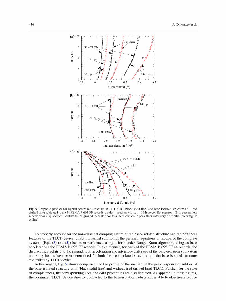
Fig. 9 Response profiles for hybrid-controlled structure (BI + TLCD—black solid line) and base-isolated structure (BI—reddashed line) subjected to the 44 FEMA P-695-FF records: circles—median; crosses—16th percentile; squares—84th percentiles;a peak floor displacement relative to the ground; b peak floor total acceleration; c peak floor interstory drift ratio (color figureonline)
To properly account for the non-classical damping nature of the base-isolated structure and the nonlinearfeatures of the TLCD device, direct numerical solution of the pertinent equations of motion of the completesystems (Eqs. (3) and (5)) has been performed using a forth order Runge–Kutta algorithm, using as baseaccelerations the FEMA P-695-FF records. In this manner, for each of the FEMA P-695-FF 44 records, thedisplacement relative to the ground, total acceleration and interstory drift ratio of the base-isolation subsystemand story beams have been determined for both the base-isolated structure and the base-isolated structurecontrolled by TLCD device.
In this regard, Fig. 9 shows comparison of the profile of the median of the peak response quantities ofthe base-isolated structure with (black solid line) and without (red dashed line) TLCD. Further, for the sakeof completeness, the corresponding 16th and 84th percentiles are also depicted. As apparent in these figures,the optimized TLCD device directly connected to the base-isolation subsystem is able to effectively reduce
Optimal design of tuned liquid column dampers in base-isolated structures 451
-4
-2
0
2
4
0 20 40 60 80 100time [s]
grou
nd a
ccel
erat
ion
[m/s
2 ](a)
Imperial Valley record
0 20 40 60 80 100
E
time [s]
(b)
San Fernando record
Fig. 10 Two accelerograms of the FEMA P-695-FF record set: a Imperial Valley record; b San Fernando record
-0.4
-0.2
0.0
0.2
0.4
base
dis
plac
emen
t re
lativ
e to
gro
und
[m]
(a)Imperial Valley record
-0.4
-0.2
0.0
0.2
0.4B
(b)Imperial Valley record
roof
dis
plac
emen
t re
lativ
e to
bas
e [m
]
-0.4
-0.2
0.0
0.2
0.4
0 20 40 60 80 100time [s]
base
dis
plac
emen
t re
lativ
e to
gro
und
[m]
(c)San Fernando record
-0.4
-0.2
0.0
0.2
0.4
0 20 40 60 80 100
B
time [s]
(d)San Fernando record
roof
dis
plac
emen
t re
lativ
e to
bas
e [m
]
Fig. 11 Response time histories of hybrid-controlled structure (black solid line) and base-isolated structure (red dashed line)subjected to the a, b Imperial Valley and c, d San Fernando earthquake records; a, c base-isolation displacement relative toground; b, d roof displacement relative to base-isolation (color figure online)
the relative displacement demand (Fig. 9a), with a reduction in the median of 16% at the base plate and 22%at the roof. The total peak accelerations remain almost unaffected by the TLCD, as shown in Fig. 9b. It isalso worth stressing that, since the interstory drift ratios decrease when a TLCD device is connected to thebase-isolation subsystem (see Fig. 9c), this reduction is not achieved at their expense, as may happen whengenerally providing supplemental damping to the base-isolation subsystem [17,27].
Analogous results may also be seen from the time histories of all the response quantities. However, froma thorough analysis of the responses to each of the 44 records, it can be evidenced that there may be cases inwhich the TLCD has little effect in reducing the displacement demand of the base-isolation system. In thisrespect, two records of the considered FEMA P-695-FF record set, specifically the Imperial Valley and theSan Fernando earthquakes, are depicted in Fig. 10, while comparison among the corresponding response timehistories of the base-isolated benchmark structure with and without TLCD are shown in Fig. 11.
As evident from Fig. 11a, for the Imperial Valley earthquake record, the TLCD device yields a clearreduction in the peak base-isolation displacement (relative to the ground) of almost 35% . Further, similarfeatures can be observed for the roof displacement (relative to the base-isolation) (Fig. 11b).
On the other hand, as shown in Figs. 11c, d, a different behavior is noticeable considering the San Fernandoearthquake record. In this case, the TLCD device yields no reduction at all in terms of peak base-isolation
452 A. Di Matteo et al.
subsystem displacement, even though it clearly leads to a more rapid dissipation of the free vibration response(Fig. 11c). This phenomenon is rather common to other similar systems, such as TMD controlled structures[28] or TMD controlled base-isolated structures [27,29]. Specifically, this is due to the fact that passive controldevices (as TLCDs and TMDs) have little effects on the structural responses in the first few seconds of theexcitation. Therefore, TLCDs cannot appreciably reduce maximum base-isolation subsystem displacement ifthemaximum response occurs early in the earthquake record, as in the case of the San Fernando groundmotion.For such excitation, the use of an active TLCD device would be recommended [14,19,32]. Nevertheless, sincethe overall effect of the TLCD on the base-isolation system, for the considered FEMA P-695-FF record set,is a clear reduction in all structural displacement and drift ratio demands, as already highlighted in Fig. 9, thispassive control device appears to be rather effective in decreasing the displacement demand of the base-isolationsubsystem. Moreover, taking into account the previously described TLCD-positive features (easy installation,low maintenance, mass of water utilizable for firefighting too), and considering that such a device would bepositioned on the ground level, the proposed TLCD-controlled base-isolated structure is simple enough forpractical implementation,when a reduction in the displacement demandof the base-isolation system is required.
6 Conclusions
In this paper, the effect of a tuned liquid column damper (TLCD) device on the seismic response of base-isolatedstructures has been investigated. The pertinent equations ofmotion of amulti-degree-of-freedom (MDOF)base-isolated structure, controlled at the base through a TLCD, have been introduced. Considering a Gaussian whitenoise model of the ground excitation, and under some assumptions regarding the base-isolation subsystem, astraightforward procedure for the optimal design of such a device has been proposed, aiming at maximally con-trol the seismic response of the base-isolated structure. In order to prove the reliability of the proposed approach,comparison with the classical iterative statistical linearization technique (SLT) has been presented, showing asatisfactory agreement between the two approaches, even when the aforementioned assumptions are removed.
On this base, a direct optimization procedure of the TLCD design parameters has been performed, andoptimal design charts have been introduced as a ready-to-use practical design tool. Comparison with theoptimal parameters obtained by a rather elaborate numerical optimization procedure, based on the classicaliterative SLT, has been carried out, leading to very small discrepancies especially in terms of control per-formances. Note, however, that a significant reduction in computational effort has been achieved with theproposed straightforward approach.
To show the influence of the non-stationary nature of real ground motions, the control performance of theTLCD device connected to the base-isolated structure has been examined, employing time-history analysesusing the 44 recorded ground motions of the FEMA P-695 far-field set, and considering a 20-story benchmarkbase-isolated shear-type frame structure. It has been shown that the TLCD device can lead to a 16% reductionin the median of the peak base-isolation displacement, compared to the base-isolated structure without TLCD.It is also worth stressing that similar reduction has been reached for other response quantities, such as roof peakdisplacement and interstory drift ratio. However, the total acceleration demands remain almost unaffected bythe TLCD. Further, from the time-history analyses it has been found that, although the TLCD has moderateeffect on the peak response in case of earthquake records with early large pulse (as also happens with otherpassive control devices), it can add damping to the structure to reduce the subsequent free vibration response.
For sake of simplicity, the main structure and the base-isolation subsystem have been assumed to be linearelastic. Clearly, many real base-isolation systems may show characteristic nonlinear features. Nevertheless,the herein developed analysis would be equally applicable by utilizing, for instance, an equivalent linearizationtechnique to partially take into account for the effect of the nonlinearity.
Finally, considering the advantageous characteristics of the TLCD devices and its overall beneficial effectsin controlling the seismic response of base-isolated structures, TLCDs can be regarded as a practical andappealing means to reduce the displacement demands of the base-isolation subsystem. In any case, it is hopedthat results presented in this paper provide valuable insights to researchers and engineers contemplating theuse of TLCDs in base-isolated structures.
7 Appendix A
In this appendix, the displacement transfer functions of the equivalent linear equations of motion (7) arepresented. In this respect, the Fourier transform of system (7) yields
Optimal design of tuned liquid column dampers in base-isolated structures 453
Xb (ω)[−ω2 (1 + μl) + 2iω ζbωb + ω2
b
] − ω2αμlY (ω) − ω2μ1X1 (ω) = − (1 + μl) Xg (ω) ,
− ω2αXb (ω) + Y (ω)[−ω2 + 2iω ζlωl + ω2
l
] = −α Xg (ω) ,
− ω2Xb (ω) + X1 (ω)[−ω2 + 2iω ζ1ω1 + ω2
1
] = −Xg (ω) . (27)
Therefore, the base-isolation displacement transfer function (Hb (ω) = Xb (ω) /Xg (ω)) can be written as
Hb (ω) = (1 + μl) + ω2α2μlc(ω)
+ ω2μla(ω)
−b (ω) + ω4α2μlc(ω)
+ ω2μla(ω)
, (28)
while the main structure displacement transfer function (HX1 (ω) = X1 (ω) /Xg (ω)) and liquid columndisplacement transfer function, respectively, are
HX1 (ω) = 1
a (ω)
[−1 + ω2Hb (ω)], HY (ω) = α
c (ω)
[−1 + ω2Hb (ω)]
(29)
in which
a (ω)=−ω2 + iω2ζ1ω1 +ω21, b (ω)=−ω2 (1 + μl)+ iω2ζbωb +ω2
b, c (ω)=−ω2 + iω2ζlωl +ω2l . (30)
These parameters can be directly used to evaluate the statistics of the equivalent linear system in Eq. (7),necessary for the iterative SLT.
Acknowledgements Open access funding provided by University of Innsbruck and Medical University of Innsbruck.
Open Access This article is distributed under the terms of the Creative Commons Attribution 4.0 International License (http://creativecommons.org/licenses/by/4.0/), which permits unrestricted use, distribution, and reproduction in any medium, providedyou give appropriate credit to the original author(s) and the source, provide a link to the Creative Commons license, and indicateif changes were made.
References
1. Adam, C., Hruska, A., Kofler, A.: Elastic structures with tuned liquid column dampers. In: M. Durakbasa, A. Afjehi,P. Osanna (eds.) Proceedings of the of the XVI IMEKO (International Measurement Confederation) World Congress, vol.VII, pp. 351–356 (2000)
2. Arfiadi, Y., S, H.M.N.: Hybrid base isolation-passivemass damper systems. In: Computing in Civil andBuilding Engineering,pp. 279–286. Stanford, USA (2000)
3. Chang, C.:Mass dampers and their optimal designs for building vibration control. Eng. Struct. 21(5), 454–463 (1999). https://doi.org/10.1016/S0141-0296(97)00213-7
4. Di Matteo, A., Lo Iacono, F., Navarra, G., Pirrotta, A.: Direct evaluation of the equivalent linear damping for TLCD systemsin random vibration for pre-design purposes. Int. J. Nonlinear Mech. 63(C), 19–30 (2014)
5. Di Matteo, A., Lo Iacono, F., Navarra, G., Pirrotta, A.: Experimental validation of a direct pre-design formula for TLCD.Eng. Struct. 75(C), 528–538 (2014)
6. DiMatteo, A., Lo Iacono, F., Navarra, G., Pirrotta, A.: Innovativemodeling of tuned liquid column dampermotion. Commun.Nonlinear Sci. Numer. Simul. 23(1–3), 229–244 (2015)
7. Di Matteo, A., Lo Iacono, F., Navarra, G., Pirrotta, A.: Optimal tuning of tuned liquid column damper systems in randomvibration by means of an approximate formulation. Meccanica 50(3), 795–808 (2015). https://doi.org/10.1007/s11012-014-0051-6
8. Di Matteo, A., Di Paola, M., Pirrotta, A.: Innovative modeling of tuned liquid column damper controlled structures. SmartStruct. Syst. 18(1), 117–138 (2016)
9. Di Matteo, A., Lo Iacono, F., Navarra, G., Pirrotta, A.: The tlcd passive control: numerical investigations vs experimentalresults. In: ASME 2012 International Mechanical Engineering Congress and Exposition Dynamics, Control and Uncertainty,Parts A and B, vol. 4, pp. 1283–1290. ASME, New York (2012). https://doi.org/10.1115/IMECE2012-86568
10. FEMA P-695: Quantification of Building Seismic Performance Factors. Technical Representative, Federal EmergencyAgency, Washington, D.C. (2009)
11. Fu, C., Ziegler, F.: Vibration prone multi-purpose buildings and towers effectively damped by tuned liquid column-gasdampers. Asian J. Civil Eng. 10(1), 21–56 (2010)
12. Hochrainer, M.J., Ziegler, F.: Tuned liquid column gas damper in structural control: the salient features of a general purposedamping device and its application in buildings, bridges and dams. In: Lagaros, N.D. et al. (eds.) Design Optimization ofActive and Passive Structural Control Systems, Chap. 7, pp. 150–179. Information Science Reference, Hershey, USA (2013)
14. Hochrainer, M.J., Ziegler, F.: Control of tall building vibrations by sealed tuned liquid column dampers. Struct. ControlHealth Monit. 13(6), 980–1002 (2006). https://doi.org/10.1002/stc.90
15. Kareem, A.: Selected papers from the ninth international symposium on wind engineering modelling of base-isolated build-ings with passive dampers under winds. J. Wind Eng. Ind. Aerodyn. 72, 323–333 (1997). https://doi.org/10.1016/S0167-6105(97)00232-8
16. Kelly, J.M.: Aseismic base isolation: review and bibliography. Soil Dyn. Earthq. Eng. 5(4), 202–216 (1986). https://doi.org/10.1016/0267-7261(86)90006-0
17. Kelly, J.M.: The role of damping in seismic isolation. Earthq. Eng. Struct. Dyn. 28(1), 3–20 (1999). https://doi.org/10.1002/(SICI)1096-9845(199901)28:1<3::AID-EQE801>3.0.CO;2-D
18. Khalid, B., Ziegler, F.: A novel aseismic foundation system for multipurpose asymmetric buildings. Archive Appl. Mech.82(10), 1423–1437 (2012). https://doi.org/10.1007/s00419-012-0667-8
19. La Duc, V., Adam, C.: General on-off damping controller for semi-active tuned liquid column damper. J. Vib. Control (2016).https://doi.org/10.1177/1077546316648080
20. Love, J., Tait, M., Toopchi-Nezhad, H.: A hybrid structural control system using a tuned liquid damper to reduce the windinduced motion of a base isolated structure. Eng. Struct. 33(3), 738–746 (2011). https://doi.org/10.1016/j.engstruct.2010.11.027
21. Palazzo, B., Betti, L.: Combined control strategies: base isolation and tuned mass damping. ISET J. Earthq. Technol. 36,121–137 (1999)
22. Palazzo, B., Petti, L.: Aspects of passive control of structural vibrations. Meccanica 32(6), 529–544 (1997). https://doi.org/10.1023/A:1004244221103
23. Perez, R., Behdinan, K.: Particle swarm approach for structural design optimization. Comput. Struct. 85(19–20), 1579–1588(2007). https://doi.org/10.1016/j.compstruc.2006.10.013
24. Reiterer, M., Ziegler, F.: Bi-axial seismic activation of civil engineering structures equipped with tuned liquid columndampers. J. Seismol. Earthq. Eng. 6(3), 45–60 (2004)
25. Reiterer, M., Ziegler, F.: Control of pedestrian-induced vibrations of long-span bridges. Struct. Control Health Monit. 13(6),1003–1027 (2006). https://doi.org/10.1002/stc.91
26. Roberts, J.B., Spanos, P.D.: Random Vibration and Statistical Linearization. Wiley, New York (1990)27. Taniguchi, T., Kiureghian, A.D., Melkumyan, M.: Effect of tuned mass damper on displacement demand of base-isolated
structures. Eng. Struct. 30(12), 3478–3488 (2008). https://doi.org/10.1016/j.engstruct.2008.05.02728. Tributsch, A., Adam, C.: Evaluation and analytical approximation of Tuned Mass Damper performance in an earthquake
environment. Smart Structures and Systems 10, 155–179 (2012)29. Tsai, H.C.: The effect of tuned-mass dampers on the seismic response of base-isolated structures. Int. J. Solids Struct. 32(8),
1195–1210 (1995). https://doi.org/10.1016/0020-7683(94)00150-U30. Won, A.Y., Pires, J.A., Haroun, M.A.: Third international stochastic structural dynamics conference performance assess-
ment of tuned liquid column dampers under random seismic loading. International Journal of Non-Linear Mechanics32(4), 745–758 (1997). https://doi.org/10.1016/S0020-7462(96)00118-7. http://www.sciencedirect.com/science/article/pii/S0020746296001187
31. Xiang, P., Nishitani, A.: Optimum design for more effective tuned mass damper system and its application to base-isolatedbuildings. Struct. Control Health Monit. 21(1), 98–114 (2014). https://doi.org/10.1002/stc.1556
32. Yalla, S.K., Kareem, A.: Semiactive tuned liquid column dampers: experimental study. J. Struct. Eng. 129(7), 960–971 (2003)33. Yang, J.N., Danielians, A., Liu, S.C.: Aseismic hybrid control systems for building structures. J. Eng. Mech. 117(4), 836–853
(1991)34. Ziegler, F.: The tuned liquid column damper as a cost-effective alternative for the mechanical damper in civil engineering
structures. J. Acoust. Vib. 12, 25–39 (2007)35. Ziegler, F.: Special design of tuned liquid column-gas dampers for the control of spatial structural vibrations. Acta Mech.


![Vibration suppression of cables using tuned inerter dampers · tuned viscous mass dampers [28,29], tuned mass-damper-inerter systems [30] and tuned inerter dampers (TID) [31]. Unlike](https://static.documents.pub/doc/80x56/5ebe7d97c8153850be39552a/vibration-suppression-of-cables-using-tuned-inerter-dampers-tuned-viscous-mass-dampers.jpg)


