Optimal Power Flow with Power Flow Routers Junhao Lin, Student Member, IEEE, Victor O. K. Li, Fellow, IEEE, Ka-Cheong Leung, Member, IEEE, and Albert Y.S. Lam, Member, IEEE Abstract—Power flow routing is an emerging control paradigm for the dynamic control of electric power flows. In this paper, we propose a generic model of a power flow router (PFR) and incorporate it into the optimal power flow (OPF) problem. First, a generic PFR architecture is proposed to encapsulate the desired functions of PFRs. Then, the load flow model of PFRs is developed and incorporated into the OPF framework. To pursue global optimality of the non-convex PFR-incorporated OPF (PFR- OPF) problem, we develop a semidefinite programming (SDP) relaxation of PFR-OPF. By introducing the regularization terms that favor a low-rank solution and tuning the penalty coefficients, a rank-1 solution can be obtained and used for recovering an optimal or near-optimal solution of the PFR-OPF and the results are verified in numerical tests. The efficacy of the PFR-OPF framework allows us to investigate the impact of PFR integration. With the system loadability as an example, the numerical results show that remarkable enhancement can be achieved by installing PFRs at certain critical buses of the network. Index Terms—power flow routers, optimal power flow, convex relaxation, semidefinite programming. NOMENCLATURE Sets N Index set of buses. E Index set of transmission lines. Ω i Index set of one-hop neighbors of Bus i. X Set of decision variables of the non-convex PFR-OPF problem. b X Set of decision variables of the relaxed PFR- OPF problem. J m The mth bag of tree decomposition. I m Set of matrix variable W’s diagonal entries that correspond to the branch terminal voltages of the buses/PFRs in bag J m . L s Index set of transmission lines selected for penalization. Parameters y ik Transmission line admittance of Branch (i, k). g ik Line conductance of Branch (i, k). b ik Line susceptance of Branch (i, k). c ik Shunt capacitance of Branch (i, k). U i,min Lower bound of bus voltage V i . U i,max Upper bound of bus voltage V i . This research is supported in part by the Theme-based Research Scheme of the Research Grants Council of Hong Kong, under Grant No. T23-701/14-N. A.Y.S. Lam was also supported in part by the Seed Funding Programme for Basic Research of The University of Hong Kong under Grant 201601159009. The authors are with the Department of Electrical and Electronic Engineer- ing, The University of Hong Kong, Pokfulam, Hong Kong (e-mail: {jhlin, vli, kcleung, ayslam}@eee.hku.hk). T i k ,min Lower bound of transformer ratio T i k of PFR i in Branch (i, k). T i k ,max Upper bound of transformer ratio T i k of PFR i in Branch (i, k). β i k ,min Lower bound of phase shift β i k of PFR i in Branch (i, k). β i k ,max Upper bound of phase shift β i k of PFR i in Branch (i, k). γ i k ,max Upper bound of series voltage tap ratio γ i k of PFR i in Branch (i, k). Q Ci k ,min Lower bound of reactive power compensation Q Ci k of PFR i in Branch (i, k). Q Ci k ,max Upper bound of reactive power compensation Q Ci k of PFR i in Branch (i, k). S ik,max Upper bound of the magnitude of complex power flow of Branch (i, k). ε r Penalty coefficient for regularization. ε s Penalty coefficient for apparent power losses. Variables V i Voltage of Bus i or voltage of common bus of PFR i. V i k Branch terminal voltage of PFR i in Branch (i, k). T i k Transformer ratio of PFR i in Branch (i, k). β i k Phase shift of PFR i in Branch (i, k). γ i k Tap ratio of series voltage injection of PFR i in Branch (i, k). Q Ci k Reactive power compensation of PFR i in Branch (i, k). S i Complex power of aggregate local power in- jection of Bus/PFR i. S ik Complex power flow from Bus/PFR i to Bus/PFR k. V Column vector obtained by stacking all the branch terminal voltage variables. W Auxiliary matrix variable corresponding to vector of branch terminal voltage V. W i k Diagonal entry of matrix variable W corre- sponding to branch terminal voltage V i k . W i k lm Off-diagonal entry of matrix variable W cor- responding to branch terminal voltages V i k and V lm . W i Auxiliary variable corresponding to bus volt- age V i . Π i k Auxiliary variable corresponding to trans- former ratio T i k . Γ i k Auxiliary variable corresponding to series voltage tap ratio γ i k .
Transcript
Optimal Power Flow with Power Flow RoutersJunhao Lin, Student Member, IEEE, Victor O. K. Li, Fellow, IEEE, Ka-Cheong Leung, Member, IEEE,
and Albert Y.S. Lam, Member, IEEE
Abstract—Power flow routing is an emerging control paradigmfor the dynamic control of electric power flows. In this paper,we propose a generic model of a power flow router (PFR) andincorporate it into the optimal power flow (OPF) problem. First,a generic PFR architecture is proposed to encapsulate the desiredfunctions of PFRs. Then, the load flow model of PFRs is developedand incorporated into the OPF framework. To pursue globaloptimality of the non-convex PFR-incorporated OPF (PFR-OPF) problem, we develop a semidefinite programming (SDP)relaxation of PFR-OPF. By introducing the regularization termsthat favor a low-rank solution and tuning the penalty coefficients,a rank-1 solution can be obtained and used for recovering anoptimal or near-optimal solution of the PFR-OPF and the resultsare verified in numerical tests. The efficacy of the PFR-OPFframework allows us to investigate the impact of PFR integration.With the system loadability as an example, the numerical resultsshow that remarkable enhancement can be achieved by installingPFRs at certain critical buses of the network.
Index Terms—power flow routers, optimal power flow, convexrelaxation, semidefinite programming.
NOMENCLATURE
Sets
N Index set of buses.E Index set of transmission lines.Ωi Index set of one-hop neighbors of Bus i.X Set of decision variables of the non-convex
PFR-OPF problem.X Set of decision variables of the relaxed PFR-
OPF problem.Jm The mth bag of tree decomposition.Im Set of matrix variable W’s diagonal entries
that correspond to the branch terminal voltagesof the buses/PFRs in bag Jm.
Ls Index set of transmission lines selected forpenalization.
Parameters
yik Transmission line admittance of Branch (i, k).gik Line conductance of Branch (i, k).bik Line susceptance of Branch (i, k).cik Shunt capacitance of Branch (i, k).Ui,min Lower bound of bus voltage Vi.Ui,max Upper bound of bus voltage Vi.
This research is supported in part by the Theme-based Research Scheme ofthe Research Grants Council of Hong Kong, under Grant No. T23-701/14-N.A.Y.S. Lam was also supported in part by the Seed Funding Programme forBasic Research of The University of Hong Kong under Grant 201601159009.
The authors are with the Department of Electrical and Electronic Engineer-ing, The University of Hong Kong, Pokfulam, Hong Kong (e-mail: jhlin, vli,kcleung, [email protected]).
Tik,min Lower bound of transformer ratio Tik of PFRi in Branch (i, k).
Tik,max Upper bound of transformer ratio Tik of PFRi in Branch (i, k).
βik,min Lower bound of phase shift βik of PFR i inBranch (i, k).
βik,max Upper bound of phase shift βik of PFR i inBranch (i, k).
γik,max Upper bound of series voltage tap ratio γik ofPFR i in Branch (i, k).
QCik,min Lower bound of reactive power compensationQCik of PFR i in Branch (i, k).
QCik,max Upper bound of reactive power compensationQCik of PFR i in Branch (i, k).
Sik,max Upper bound of the magnitude of complexpower flow of Branch (i, k).
εr Penalty coefficient for regularization.εs Penalty coefficient for apparent power losses.
Variables
Vi Voltage of Bus i or voltage of common bus ofPFR i.
Vik Branch terminal voltage of PFR i in Branch(i, k).
Tik Transformer ratio of PFR i in Branch (i, k).βik Phase shift of PFR i in Branch (i, k).γik Tap ratio of series voltage injection of PFR i
in Branch (i, k).QCik Reactive power compensation of PFR i in
Branch (i, k).Si Complex power of aggregate local power in-
jection of Bus/PFR i.Sik Complex power flow from Bus/PFR i to
Bus/PFR k.V Column vector obtained by stacking all the
branch terminal voltage variables.W Auxiliary matrix variable corresponding to
vector of branch terminal voltage V.Wik Diagonal entry of matrix variable W corre-
sponding to branch terminal voltage Vik .Wiklm Off-diagonal entry of matrix variable W cor-
responding to branch terminal voltages Vik andVlm .
Wi Auxiliary variable corresponding to bus volt-age Vi.
Πik Auxiliary variable corresponding to trans-former ratio Tik .
Γik Auxiliary variable corresponding to seriesvoltage tap ratio γik .
hr Regularization function.Lik Apparent power loss over the series impedance
of Branch (i, k).λ Loading factor.
I. INTRODUCTION
The increase in energy demand and the integration of renew-able energy sources (RESs) are stressing the grid, promptingsystem operators to take active control measures for managingthe power flow more efficiently and intelligently. Traditionalpower flow controls may no longer be suitable for the futurepower system operation because of their limited control rangeand slow dynamic response [1]. Due to the development ofpower electronics over the past two decades [1]–[3], powerflow routing [2], [4], [5], an emerging control paradigm for thedynamic and responsive control of power flows, is a promisingsolution for power flow control.
Power flow controllers (PFCs) and power flow routers(PFRs) are the building blocks of power flow routing. In thispaper, we propose a generic model of PFRs and an optimalpower flow (OPF) framework for the analytical study of powerflow routing. We will explain our motivation and identify theresearch gap by reviewing the state-of-the-art.
The need for a smarter and more resilient grid has led tocontinuous innovations on PFCs [1]–[3] and PFRs [4], [6],[7], but the literature does not usually make a clear distinctionbetween PFCs and PFRs. To avoid ambiguity, we use PFRto refer to a control device that is able to manage multipleincoming/outgoing power flows, while PFC refers to a devicethat can only actively adjust the power flow through onetransmission line or appliance. Hence, a PFC is part of aPFR. In general, PFCs [1]–[3] control the branch power flowby modifying the parameters of a transmission line, suchas series injection of the voltage source and/or resistance,and shunt reactive power compensation. PFRs are useful forinterconnecting multiple transmission lines and interfacingappliances at different power levels [4], [6], [7]. The energyrouter [6] and the solid-state transformer (SST) [7] only focuson interfacing various types of local power injections, but theyare not designed for controlling branch power flows.
We can see that most existing research efforts on PFCs andPFRs have been devoted to the hardware implementation [1]–[3], [6], [7], whereas [4] does focus on the generic model ofa PFR. However, the PFR model proposed in [4] is just asimple combination of a computational unit and several PFCs,and it is only applicable to the distribution network. The lackof a generic functional model of PFRs has hindered network-level research on power flow routing. To overcome this, wepropose a generic PFR model that covers the necessary anddesired functions of a PFR so as to facilitate a theoretical studyof power flow routing in the power network.
We focus on the modelling of PFRs for power systemoptimization. Although the research on load flow models ofPFCs is rich [3], [5], [8], [9], existing work on the modellingof PFRs is rather limited. Flexible AC transmission system(FACTS) devices [3], the best known PFCs, have been studiedextensively for improving asset utilization [5], [8], [9]. A
sensitivity method has been employed in [5] to analyze theimpact of PFCs on corrective power flow control. However,due to the inherent complexity of the method, reactive poweris not considered in [5]. In general, a PFC adjusts the powerflow by its series and/or shunt sources injected over thetransmission line [3]. The change of power flow induced by theseries source of the PFC is usually converted to and modelledas power injections to both buses of the branch [5], [8], [9],since the approach preserves the symmetry of the admittancematrix and the structure of the Jacobian matrix. Differentfrom the literature, we develop the load flow model of aPFR characterized by “branch terminal voltages,” the terminalvoltages of the PFR, which is a more intuitive approach toformulate the power flow according to the PFR’s operatingprinciple.
We further incorporate the PFR model into the OPF frame-work. The OPF problem determines the optimal operatingpoints for a power system in terms of a global objectivefunction, subject to the network physics, such as Kirchhoff’scircuit laws, as well as the engineering limits of the state andcontrol variables of the system, such as inequality constraintson transmission line flows, power generations, and configura-tions of control devices [10], [11]. In the proposed PFR model,the voltage of a conventional bus is augmented and evolvesinto multiple branch terminal voltages to reduce the couplingamong corresponding power flows. As a result, the size of thePFR-incorporated OPF (PFR-OPF) problem is proportional tothe number of branches, and comparable to the conventionalOPF problem whose size is proportional to the number ofbuses since the power network is in general a sparse graph.Hence, existing nonlinear programming (NLP) solvers, suchas interior point methods used in our numerical tests, are stillable to obtain a local optimal solution of the non-convex PFR-OPF problem. Although the existing power injection method[5], [8], [9] and the model proposed in this paper are notessentially different since they both aim to model the controlabilities of PFCs and PFRs, the proposed PFR model is moreamenable for applying the convex relaxation to the PFR-OPFproblem. In the power injection method, the series injectedsource of PFC introduces nonlinear terms which are not easyto relax, especially for those characterizing the phase-shiftingeffect.
In general, the alternating-current (AC) OPF problem ischallenging due to its non-convexity and usually very largeproblem size [10]. The non-convexity stems from the nonlinearpower flow equation due to Kirchhoff’s laws, as well asthe nonlinear or even discrete characteristics of some controlvariables, such as tap-changing transformers [10], [12]. Theproblem size can be very large in the real-world industrialapplication not only because of the scale of the power system,but also more significantly due to the number (tens of thou-sands or more) of postulated contingencies [10], [12]. In theliterature, various approaches have been proposed to tacklethose respective challenges [10], [13]. Many nonlinear pro-gramming (NLP) approaches, such as quadratic programming,Lagrangian relaxation, heuristic algorithms, and interior-pointmethods, have been proposed to cope with the non-convexity[10], [13]. In order to solve the security-constrained OPF
(SCOPF) with a large number of contingencies efficiently,various classes of approaches, including iterative contingencyselection schemes, decomposition methods, and network com-pression, have been developed [12], [14]. Some of them aremature and capable of finding at least the local optimum oflarge-scale SCOPF problems with up to 3000 buses [14] oreven 9000 buses and 12000 contingencies [12].
In this research, we only consider the basic and continuousscenarios of the AC OPF problem, and do not include con-tingencies and discrete variables. With such simplifications,this paper aims to address the non-convexity introduced byKirchhoff’s laws as well as PFCs and PFRs, and pursuesglobal optimality of the PFR-OPF problem through convexrelaxation. However, it is worth pointing out that the compu-tational challenges induced by the security constraints and thediscrete variables can be formidable as both the numbers ofcontingencies and discrete variables can be huge, thousands ormore in the real-world industrial OPF problems. Therefore, inthe industrial practice, given the stringent time constraint toprovide a solution, achieving global optimality of the OPFsolution is often not the primary concern since it can betoo time-consuming [14]. Although the solution method forthe OPF problem proposed in this paper is not designed toaddress the large-scale SCOPF problem, we expect that theproposed PFR-OPF framework is extensible to incorporatethe security constraints. In fact, due to their fast-responsecapability, PFCs and PFRs can be very powerful resources toperform post-contingency corrective control [5]. The flexibleSCOPF framework proposed in [5] incorporates PFCs into thecorrective SCOPF problem, while the ability to handle a largecontingency set is not discussed. When the PFCs and PFRs aretreated as re-dispatchable resources in the corrective SCOPFproblem, the coupling effect among their post-contingencydecision variables would be a new challenge due to thenonlinear control regions of PFCs and PFRs, especially forthe phase shifting effect. Hence, existing methods for thelarge-scale SCOPF problem, such as contingency selection anddecomposition [12], [14], may not be applicable directly. It isan important problem and will be our future work.
In recent years, there have been extensive research efforts todevelop convex relaxation methods for the conventional OPFproblems in pursuit of the global optimality [15]–[23]. Themain focus of these convex relaxation methods in [15]–[23],similar to our work, is to tackle the non-convexity due toKirchhoff’s laws, and thus they do not consider discrete vari-ables. Among these proposals, only [18] studies the SCOPFproblem but it does not account for a large contingency set.While the local solution techniques usually find the globaloptimal solutions in practice [14], they may fail to convergeor converge to a local optimum [13], [24]. Moreover, they areunable to guarantee global optimality of the solutions. Thesecond-order cone programming (SOCP) relaxation is able toglobally solve the OPF problems for the radial networks thatsatisfy certain technical conditions [17], [23]. The semidefiniteprogramming (SDP) relaxation has received much researchattention [15], [18], [19], [21] since it is able to obtain theglobal optimal or near-optimal solutions for a broad class ofmeshed networks. Voltage phasors can be recovered success-
fully from the solution if the rank of its matrix variable is equalone. While the structure of feasible region and the existenceof local optima may render the SDP relaxation unable toproduce a physically meaningful solution [24], penalization[18], [19] and Laplacian-based [21] approaches have beenproposed to encourage a rank-1 solution so that a feasibleand globally near-optimal solution to the original non-convexOPF problem can be obtained for many test cases, includingsome large networks with up to 3000 buses. Recently, theSDP relaxation have been generalized to a family of “momentrelaxation” [16], [20], [22] which is essentially a polynomialoptimization approach and seeks to attain tighter relaxationby gradually increasing the order of relaxation if the lower-order relaxations fail. While higher-order moment relaxationsare able to globally solve a broader class of OPF problemscomparing to the first-order relaxation, i.e., the SDP relaxation,the computational cost grows very quickly as the relaxationorder increases [16]. Therefore, sparsity-exploiting technique[20] has been proposed to reduce the computational burden.And penalization approach [22] has also been adopted toimprove numerical performance when a near-optimal solutionis obtained.
To pursue global optimality of the PFR-OPF problem, wederive an SDP relaxation of the original problem. While thereis much research on the convex relaxation of the conventionalOPF problem [15]–[23] as discussed, we found no existingwork that applies it to an OPF problem with PFCs or PFRs.The convex relaxation for the PFR-OPF poses a new chal-lenge that has not been studied before. Since the relationshipamong the terminal voltages of a PFR is highly nonlinearand non-convex due to the enhanced voltage controllability,it is difficult to construct a relaxation that preserves suchcoupling and leads to an exact solution for successful recoveryof voltage phasors. While it has been shown that the SDPrelaxation is able to handle variable real transformer ratiosand shunt elements [15], the exact relaxation for the seriesinjected source of PFC and PFR, such as the phase shifter,has not been tackled yet. In fact, existing research on theSOCP relaxation [17] assumes that phase shifters possessunlimited phase-shifting capabilities or their capabilities wouldnot be the binding constraints so as to avoid incorporatingthe nonlinear phase-shifting effect into the OPF problem.However, this ideal assumption may not always hold. In thisresearch, we account for the capability of phase shifters andmodel the phase-shifting effect explicitly in PFR-OPF problemas well as its SDP relaxation. It is achieved by relaxing partof the coupling constraints and incorporating the regularizationterms that favor an exact solution into the objective function.As verified in our numerical tests, such regularization helpsimprove the quality of the solution significantly while it onlyhas a negligible effect on the optimal value of the originalobjective. In addition, we show excellent compatibility of theproposed PFR model in the sense that existing techniques forimproving the performance of the SDP relaxation, such as thepenalization method to solicit a low-rank solution [18], [19],and the graph-theoretic decomposition method to reduce thecomputational complexity [18], can naturally be adapted toour PFR-OPF framework. Although the SDP relaxation may
fail to find a physically meaningful solution for a few powernetworks with certain configurations as studied in [20], [22],[24], the remedial approaches [18], [19] adopted are able toimprove its quality of solutions significantly and broaden itsrange of applicable cases, such as the network with up to3000 buses as evaluated in our numerical study in SectionV. The generalization of the SDP relaxation for the PFR-OPF problem into the higher-order moment relaxation is anongoing research and remains challenging since the phase-shifting effect would render the rectangular representation ofvoltage variables in the moment relaxation [16], [20], [22]nonlinear and hence difficult to relax as the relaxation ordergoes above one. Nonetheless, we consider that this researchmay serve as the initial efforts to apply convex relaxation tothe OPF problem with a set of nonlinear control variables forvoltages.
To summarize, we propose a generic PFR model and an OPFframework incorporating PFRs. Our contributions are listed asfollows:• The proposed PFR model encapsulates the desired fea-
tures of PFRs, and is amenable for implementation andfor the theoretical study of power flow routing.
• The load flow model of PFRs is developed and incor-porated successfully into the OPF framework for powerflow analysis and grid optimization.
• We derive a computationally efficient SDP relaxationof the PFR-OPF problem and design the regularizationmethod to facilitate a rank-1 solution. The benefit of PFRsin enhancing the system loadability is evaluated by theproposed framework.
This paper extends our prior work [25] with substantialdifferences and improvements as follows:• This paper improves the PFR model by designing a
generic formulation of the branch terminal voltages so asto adapt the model to various grid components includingconventional buses and PFCs.
• This paper solves the PFR-OPF problem through anSDP relaxation, which is more realistic than the SOCPrelaxation in [25], which requires a sufficient number ofideal phase shifters to ensure exact relaxation.
• This paper compares the results of the non-convex andrelaxed PFR-OPF problems, and analyzes the quality ofthe SDP solution by varying the penalty coefficients.
The remainder of this paper is structured as follows. InSection II, the generic architecture of the PFR model isproposed. In Section III, the load flow model of PFRs isdeveloped and incorporated into the OPF framework. Then,the PFR-OPF problem is relaxed and solved through the SDPrelaxation in Section IV. Case studies are presented and thenumerical results are analyzed in Section V. Finally, SectionVI draws the conclusions.
II. GENERIC MODEL OF POWER FLOW ROUTERS
A PFR can manage all of its incoming/outgoing power flowsintelligently, and coordinate with other grid components tomaintain the system stability. In general, a PFR should achievethe following functions:
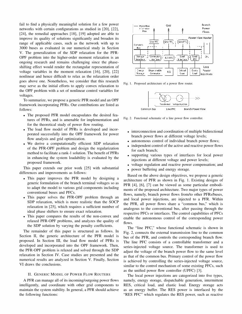
Fig. 1. Proposed architecture of a power flow router.
Fig. 2. Functional schematic of a line power flow controller.
• interconnection and coordination of multiple bidirectionalbranch power flows at different voltage levels;
• autonomous control of individual branch power flows;• independent control of the active and reactive power flows
for each branch;• supporting various types of interfaces for local power
injections at different voltage and power levels;• voltage regulation and reactive power compensation; and• power buffering and energy storage.
Based on the above design objectives, we propose a genericarchitecture of PFR as shown in Fig. 1. Existing designs ofPFR [4], [6], [7] can be viewed as some particular embodi-ments of the proposed architecture. Two major types of powerflows, namely, branch power flows from/to other PFRs/buses,and local power injections, are injected to a PFR. Withinthe PFR, all power flows share a “common bus,” which isanalogous to the conventional bus, after passing through therespective PFCs or interfaces. The control capabilities of PFCsenable the autonomous control of the corresponding powerflows.
The “line PFC,” whose functional schematic is shown inFig. 2, connects the external transmission line to the commonbus of the PFR, and controls the corresponding branch flow.The line PFC consists of a controllable transformer and aseries-injected voltage source. The transformer is used toadjust the voltage of the branch power flow to the same levelas that of the common bus. Primary control of the power flowis achieved by controlling the series-injected voltage source,similar to the control mechanism of some existing PFCs, suchas the unified power flow controller (UPFC) [3].
The local power injections are categorized into five types,namely, energy storage, dispatchable generation, intermittentRES, critical load, and elastic load. Energy storage actsas an energy buffer. The RES power is interfaced by the“RES PFC” which regulates the RES power, such as reactive
power compensation and voltage regulation. Local demand isclassified into the critical load and the elastic load. The formerhas to be met in real time while the latter may be a deferrableload or a non-critical load managed by the “load PFC”. The“load PFC” that interconnects the common bus and the elasticload can be an electric spring [26] to regulate the commonbus voltage and absorb the fluctuations of the RES power.The energy storage, dispatchable generator, and critical loadwould be connected to the common bus through respectiveinterfaces.
The operations of the PFCs and interfaces are coordinatedby a central processing unit (CPU) which is the central con-troller of the PFR. PFRs can also communicate and coordinatewith each other via some other controllers in the network.
It should be noted that the architecture given in Fig. 1 isan ideal configuration. A practical PFR may sacrifice certainpower flow control capability to strike a balance between thecontrol capacity and the cost of the device.
III. LOAD FLOW MODEL AND OPTIMAL POWER FLOW
A. Load Flow Model of Power Flow Router
The load flow model of a PFR is developed based on thePFR model discussed in Section II. Consider a power networkwith N buses modelled as a connected undirected graph,denoted by G = (N , E) with the bus set N := 1, 2, . . . , Nand the set of transmission lines or branches E ⊆ N × N .A branch (i, k) ∈ E with its two terminal buses i, k ∈ N ismodelled by the equivalent π circuit with the line admittanceyik = gik + jbik, where gik ≥ 0 and bik ≤ 0 denote theconductance and susceptance of branch (i, k), respectively,and the shunt capacitance cik = cki ≥ 0 as illustrated inFig. 3. Denote the set of one-hop neighbors of each bus i ∈ Nas Ωi ⊆ N . Note that Branch (i, k) and Branch (k, i) areregarded as the same branch since G is undirected.
By abuse of notation, we denote the PFR installed at Busi ∈ N as PFR i. The branch power flows and the local powerinjections of Bus i are interfaced to PFR i. The common busof PFR i is characterized by the voltage Vi ∈ C analogous tothat of a conventional bus, with the operation range given as:
Ui,min ≤ |Vi| ≤ Ui,max (1)
where the operator |·| takes the magnitude.For each one-hop connected Bus/PFR k ∈ Ωi of PFR i,
we define a “branch terminal voltage” Vik ∈ C, indicatingthe terminal voltage of PFR i for Branch (i, k). According toFig. 2, the relationship between the common bus voltage Viand the branch terminal voltage Vik can be modelled by:
Vik = Tikejβik (1 + γik)Vi, (2)
where βik ∈ R is the phase shift of the transformer, andTik ∈ R represents the transformer ratio. Moreover, as acommon practice for the series voltage compensation [1], [3],we assume that the series voltage that the line PFC can injectis a fraction γik ∈ C of the voltage Tike
jβikVi, which isequal to the grid-side voltage of the line PFC when the seriesvoltage compensation is zero. In addition, the line PFC, as apower electronic device, of PFR i in branch (i, k) may possess
Fig. 3. Notations for a branch (i, k).
certain extra capability of reactive power compensation whichis modelled by the reactive power injection QCik ∈ R. Thecontrollable ranges of Tik , βik , γik , and QCik are constrainedby respective upper and lower bounds as follows:
where γik,max ∈ [0, 1] characterizes the capability of the seriesvoltage injection.
Denote the complex power flow from PFR i to Bus/PFRk ∈ Ωi as Sik = Pik + jQik which satisfies Ohm’s law as:
Sik = Vik(Vik − Vki)∗y∗ik − j |Vik |2cik (7)
where * denotes the conjugate operator of a complex number.Symmetrically, the branch terminal voltage Vki on the other
end of Branch (i, k) and the complex power flow Ski aremodelled as:
Vki = Tkiejβki (1 + γki)Vk (8)
Ski = Vki(Vki − Vik)∗y∗ik − j |Vki |2cki (9)
Let Si = Pi + jQi denote the complex power of the aggre-gate local power injection of PFR i. Then, if the conversionlosses of the line PFCs are neglected, the power balanceequation for PFR i is formulated as:
Si =∑k∈Ωi
Sik. (10)
From (7) and (9), the branch power flows Sik and Skiare controlled by the terminal voltages Vik and Vki of thetwo buses/PFRs on both ends. According to (2), for a fixedcommon bus voltage Vi, each terminal voltage Vik |k ∈ Ωiof PFR i can be controlled autonomously by the correspondingline PFC. On the other hand, the PFR is more than a simpleaggregation of a number of PFCs since the terminal voltagesof the PFCs in a PFR are not completely independent andare actually coupled weakly by the common bus voltage.This feature is characterized by the proposed PFR model.PFRs enable larger controllable ranges of the branch terminalvoltages than the voltages of the conventional buses. Hence,the achievable region of branch power flows of PFRs is greaterthan those of conventional buses. The enlarged control regionscontribute to reduction of transmission losses, relief of gridcongestion, and improvement of power transfer capability.
Since the focus of this study is on the modelling andoptimization of branch power flows, we do not go into detailson the load flow models of the local power injections. In thispaper, we only consider the simple power injection modelsof conventional generators and critical loads as formulated
in Section V-A. Nonetheless, existing sophisticated powerinjection models, such as the smart load model [27], can beincorporated directly into the PFR model.
The load flow model of PFR given in (1)–(10) is versatileand applicable to various types of grid components, includingconventional buses and PFCs, by setting proper lower andupper bounds of the parameters in (3)–(6).
B. PFR-Incorporated Optimal Power Flow
The load flow model of PFR developed in Section III-A willbe incorporated into the OPF problem. The OPF with PFRs isdifferent from the conventional OPF since the bus voltage hasevolved into several branch terminal voltages when the PFRis attached to the bus. Define the set of the variables as:
X :=(Si, Vi)|i ∈ N ∪ (Sik, Ski, Vik , Vki , Tik , Tki ,βik , βki , γik , γki , QCik , QCki)|(i, k) ∈ E. (11)
We minimize a global objective function f of the power net-work, subject to the power balance constraints at PFRs/buses,the constraints for the control regions of PFRs, and theconstraints for branch power flows. The general form of thePFR-incorporated OPF (PFR-OPF) is formulated as follows:
minX
f (12a)
subject to|Sik| , |Ski| ≤ Sik,max,∀(i, k) ∈ E (12b)(1), (10), ∀i ∈ N (12c)(2)–(7), ∀i ∈ N , k ∈ Ωi (12d)
The constraint in (12b) specifies the upper limits of thebranch flow magnitude to protect transmission lines. Can-didates for the scalar function f can be any economic oroperational evaluation of the system, such as the generationcost or the system loadability which will be studied in SectionV.
The PFR-OPF problem in (12) extends the conventionalOPF problem by augmenting the controllable ranges of theconventional buses. Therefore, the PFR-OPF problem is non-convex and non-deterministic polynomial-time hard (NP-hard)like the conventional OPF [15] due to the non-convex feasibleregion of power flows determined by (7) and (10). Moreover,the PFR-OPF problem entails a higher computational com-plexity than the conventional OPF problem because of theincrease in the problem size and the nonlinear relation betweenthe common bus voltage and the branch terminal voltage asindicated in (2). Nonetheless, since the power network ingeneral is sparse with a small edge-to-vertex ratio, the increasein the problem size from the order of the number of buses tothat of the number of branches is almost linear.
IV. CONVEX RELAXATION
A. Semidefinite Programming Relaxation
Inspired by the methods proposed in [15], [18], [19] forconvexifying the conventional OPF problem, we propose amethod to relax the PFR-OPF problem in (12) into an SDPproblem to seek the global optimal solution.
We introduce the auxiliary matrix variable W ∈ C2E×2E
corresponding to the branch terminal voltages as:
W := VV∗ (13)
where V ∈ C2E is defined as a column vector obtained bystacking the paired voltages Vik and Vki for every branch(i, k) ∈ E . If W replaces V in the PFR-OPF problem in (12),there are at least two additional constraints to be included inthe formulation so that V can later be recovered from W.The first constraint is W 0, which means W is positivesemidefinite. The second one is rankW = 1, which meansthe rank of W is equal to one. Without this rank constraint,the original non-convex power flow region determined by (7)and (10) is relaxed into a convex region. However, differentfrom the existing studies [15], [18], [19] on the SDP relaxationfor the conventional OPF problem, such relaxation does notsuffice to render the PFR-OPF problem convex due to thehighly nonlinear relationship between the common bus voltageand the branch terminal voltage of a PFR modelled in (2).
To tackle this issue, we develop a relaxation method whichcan not only preserve the coupling between the terminalvoltages of the PFR but also produce a rank-1 solution Wopt
for successful recovery of the voltage phasors. For ease ofpresentation, we label the diagonal entries of W as:
Wik := |Vik |2,∀i ∈ N , k ∈ Ωi, (14)
and the off-diagonal entries of W as:
Wiklm := VikV∗lm ,∀i, l ∈ N , k ∈ Ωi,m ∈ Ωl (15)
Then, taking the magnitude squared of (2), we get:
Wik = ΠikΓikWi (16)
where Wi, Πik , and Γik are defined as:
Wi := |Vi|2 ,∀i ∈ N (17)Πik := T 2
ik,∀i ∈ N , k ∈ Ωi (18)
Γik := |1 + γik |2,∀i ∈ N , k ∈ Ωi (19)
Note that the angle variable βik in (2) disappears after wedetermine its magnitude. According to (3) and (5), the feasibleregions of Πik and Γik are convex. Hence, (3), (5), and (16)can be combined into one constraint as follows:
T 2ik,min
(1− γik,max)2Wi ≤Wik
≤ T 2ik,max
(1 + γik,max)2Wi,∀i ∈ N , k ∈ Ωi(20)
Constraint (20) is convex since the feasible region of Wi islinear according to (1) and (17).
To account for the phase-shifting angle variable βik in (2)and Constraint (4) while ensuring convexity, we propose tolimit the angular difference between any two branch terminalvoltages of the same bus/PFR by:
θikil,min ≤ ∠Wikil ≤ θikil,max,∀i ∈ N , k 6= l ∈ Ωi, (21)
where θikil,min and θikil,max are the lower and upper bounds,respectively, of the angular difference ∠Wikil between Vik andVil . Due to the stability concern, a large phase shift betweenthe two branch terminal voltages should be avoided. Hence, weassume that ∠Wikil ∈ [−π2 ,
π2 ], which also makes Constraint
(21) convex. Then, we can derive the values of θikil,min andθikil,max based on (2)–(5) as follows:
From (21)–(23), we have ReWikil ≥ 0, where Re· isthe operator for getting the real part. Thus, Constraint (21) canbe explicitly expressed in the convex form as follows:
ReWikil tan θikil,min ≤ ImWikil≤ ReWikil tan θikil,max,∀i ∈ N , k 6= l ∈ Ωi, (24)
where Im· is the operator for getting the imaginary part.Then, we derive a constraint to account for the coupling
between Wi and Wikil . According to (21)–(23), we have:
cos(max|θikil,min| , |θikil,max|),∀i ∈ N , k 6= l ∈ Ωi (27)
We have developed the convex constraints (20), (24), and(27) to relax the non-convex constraint (2) and to account forthe operation range of the PFR specified in (3)–(5). However,they are still not sufficient to make the optimal solution Wopt
of the relaxed problem to be rank-1, since PFR enlarges thecontrollable ranges of its branch terminal voltages. Thus theoff-diagonal entries Wikil ,∀i ∈ N , k 6= l ∈ Ωi, related toPFR i are only coupled weakly with the diagonal entries ofW. Under such circumstance, most numerical algorithms tendto result in the highest-rank SDP solution, even though arank-1 solution may exist. To address this issue, we introducea regularization term hr that favors a low-rank solution tothe original objective function f . As discussed in [18] and[28], a penalty function that minimizes a weighted sum of thediagonal entries as well as maximizes a weighted sum of theoff-diagonal entries Wikil ,∀i ∈ N , k 6= l ∈ Ωi, can serve thispurpose. Therefore, we formulate the regularization functionhr as follows:
hr :=∑i∈N
∑k<l∈Ωi
(Wik +Wil −Wikil −Wilik) (28)
We summarize the SDP relaxation for the PFR-OPF prob-lem. Define the penalty coefficient for the regularization hr asεr ≥ 0. We also define the set of the variables of the relaxedPFR-OPF problem as:
X :=W ∪ (Si,Wi)|i ∈ N ∪ (Sik, Ski,QCik , QCki)|(i, k) ∈ E. (29)
The relaxed PFR-OPF problem is formulated as follows:
minX
f + εrhr (30a)
subject to
Si =∑k∈Ωi
(Sik + jQCik) ,∀i ∈ N (30b)
Sik = (Wik −Wikki)y∗ik − jWikcik,∀i ∈ N , k ∈ Ωi(30c)
U2i,min ≤Wi ≤ U2
i,max,∀i ∈ N (30d)QCik,min ≤ QCik ≤ QCik,max,∀i ∈ N , k ∈ Ωi (30e)|Sik| , |Ski| ≤ Sik,max,∀(i, k) ∈ E (30f)W 0 (30g)and (20), (24), (27) (30h)
Note that for a conventional bus i without a PFR or PFC,the corresponding penalty in (28), (Wik + Wil − Wikil −Wilik),∀i < l ∈ Ωi, is kept constant by Constraints (20),(24), and (27). In fact, the regularization εrhr has a negligibleeffect on the optimal value of the original objective while it isvery effective in yielding a rank-1 Wopt. This will be verifiedby our numerical tests in Section V.
B. Adapted Techniques for Performance Improvement
While the SDP relaxation for the OPF problem can facilitatethe search of the global optimum, the number of scalarvariables of its semidefinite matrix variable, such as W, growsquadratically with the size of the power network. Besidesthe issue of high dimensionality, the SDP relaxation maynot always result in a rank-1 matrix solution depending onthe problem formulation [18], [19] and the values of lineadmittances [15]. While the relaxed PFR-OPF problem in(30) will also experience these issues, we show that thegraph-theoretic decomposition method proposed in [18] forreducing the computational complexity and the penalizationmethod in [18], [19] for soliciting a low-rank solution can beadapted naturally to our PFR-OPF framework to amelioratethe situation.
As discussed in [18], the semidefinite constraint on thesquare matrix variable related to the bus voltages can bereplaced by a set of semidefinite constraints on some prin-cipal submatrices of the matrix variable without affecting theoptimality of the relaxed problem according to the chordaltheorem [29]. The dimensions of those principal submatrices,which are constructed from a tree decomposition of the powernetwork, are much lower than the full matrix variable due tothe sparsity of the network [18]. The interested readers mayrefer to [18] and the references therein for information aboutthe tree decomposition and its algorithm. By adopting thedefinition and notation of the tree decomposition in [18], wedenote the bags of a tree decomposition of the power networkas J1,J2, . . . ,JM ⊆ N , where M is the number of bags.Note that each bag Jm,m = 1, . . . ,M , is a subset of the busset N . Construct the set Im := Wik |i ∈ Jm, k ∈ Ωi, whichconsists of W’s diagonal entries that correspond to the branchterminal voltages of the buses/PFRs in Jm,m = 1, . . . ,M .Let WIm be the principal submatrix of W formed by theintersected rows and columns containing the elements in Im.
Theorem 1: The optimal objective value of the relaxed PFR-OPF problem in (30) does not change if its constraint W 0is replaced by the constraints as follows:
WIm 0,∀m ∈ 1, 2, . . . ,M. (31)
Proof: This theorem is a direct variant of Part 2 ofTheorem 1 in [18] to fit into our PFR-OPF framework. Sincethe bus voltage has evolved into several branch terminalvoltages in the PFR model, we replace the bus-related variablesin Part 2 of Theorem 1 in [18] by the branch-related variablesin Theorem 1 in this paper. Constraint (31) preserves thestructural information of the tree decomposition of the powernetwork. Therefore, the rest of the proof follows from Part 2of Theorem 1 in [18] and the chordal theorem in [29].
Theorem 1 allows us to reduce the computational complex-ity of the SDP relaxation remarkably. Take the IEEE 118-bussystem [30] as an example. There are 186 branches in thesystem, and thus W is a 372 × 372 matrix. However, thesubmatrix with the largest size among all of the M = 117submatrices in (31) according to the tree decomposition resultsis merely a 28 × 28 matrix which is less than 0.57% of thesize of W.
Furthermore, to pursue a rank-1 solution of the SDP re-laxation, [19] proposes to penalize the total reactive powergeneration, and [18] further proposes to penalize the apparentpower loss over the series impedance of the transmissionlines. While both methods can be incorporated into the PFR-OPF problem easily, we use the latter in this paper sinceit is formulated by the entries of W explicitly and allowsflexibility to adjust the total penalty by modifying the set ofthe penalized transmission lines. Similar to [18], define theapparent power loss over the series impedance of Branch (i, k)without incorporating the shunt capacitance as:
Denote the set of branches that are selected for the penaltyas Ls ⊆ E . A convenient and safe choice of Ls is tomake it equal to the branch set E of the network. [18] alsoproposes a heuristic method for designing Ls. Define thepenalty coefficient for apparent power losses as εs ≥ 0.We summarize the two adapted techniques for improving theperformance of the SDP relaxation and formulate the improvedrelaxed PFR-OPF problem as follows:
minX
f + εrhr + εs∑
(i,k)∈Ls
Lik (33)
subject to (30b)–(30f), (30h), and (31).The improved relaxed PFR-OPF problem in (33) is modified
from the relaxed problem in (30) by adding the penalizationterm of apparent power losses to the objective function, andreplacing the original SDP constraint in (30g) by a set of SDPconstraints in (31) according to the tree decomposition resultsof the power network.
V. CASE STUDY
A. Problem Specification and Performance Metric
We investigate the impact of PFR integration on systemloadability. According to [31], the loadability can be assessedby increasing all of the loads by a loading factor λ ≥ 0 untilthe system reaches the critical state. Therefore, as a specificimplementation of the PFR-OPF problem, the local power in-jections are categorized into the reactive power compensationof the PFRs, the critical loads, the dispatchable generators withthe operation ranges as follows:
Si = (PGi − PLi) + j(QGi −QLi +∑k∈Ωi
QCik),∀i ∈ N (34)
PLi + jQLi = λ(PLi0 + jQLi0),∀i ∈ N (35)PGi,min ≤ PGi ≤ PGi,max,∀i ∈ N (36)QGi,min ≤ QGi ≤ QGi,max,∀i ∈ N (37)
where PGi and QGi denote the active and reactive generations,respectively, of the generator at Bus/PFR i, i = 1, . . . ,N .Their controllable ranges are specified in (36) and (37),respectively. PLi and QLi denote the active and reactive loads,respectively, at Bus/PFR i. PLi0 ≥ 0 and QLi0 ∈ R are thebase active and reactive loads, respectively, at Bus/PFR i.
To evaluate the loadability, each of the three versions of thePFR-OPF problems in (12), (30), and (33) is extended by con-sidering λ, PGi, QGi, PLi, QLi, i = 1, . . . ,N , and Constraints(34)–(37). Finally, the objective function f is set as:
f = −∑i∈N
PLi (38)
We will assess and compare the loadabilities of the powernetwork under various penetrations and allocations of PFRsand UPFCs [3]. The reason for choosing UPFCs for com-parison with PFRs is that the UPFC has similar power flowcontrol capability as the PFR. The UPFC is one of the mostversatile PFCs and is able to regulate the bus voltage andcontrol the active and reactive power flow independently [3].While UPFCs are deployed far less commonly in the real-world power systems compared to some other FACTS devices,such as static shunt compensators (SVCs) [3], due to thecurrently high costs of UPFCs, existing academic research hasexplored and demonstrated the benefits of UPFCs in variousaspects, such as the enhancement of system stability [32] andreliability [33].
Denote the optimal loading factor as λopt obtained bysolving the PFR-OPF problems for loadability assessment.λopt will serve as the performance metric.
B. General Setup
In Sections V-D and V-E, numerical tests are performedon the standard IEEE benchmark systems with 30, 57, and118 buses. The parameter specifications of the three testedsystems follow the standard settings archived at [30], exceptfor the branch flow limits of the 57-bus and 118-bus systemswhich are not given in [30]. Without loss of generality, weset the flow limits of all branches of the test systems with57 and 118 buses to be 300 MW and 600 MW, respectively,
based on the nominal settings. This set of tests is to investigatethe effect of the penalty coefficients εr and εs of the relaxedproblem in (33) on the quality of solutions, and to evaluate theenhancement of loadability with various penetrations of PFCsand PFRs.
Furthermore, in Section V-F, we investigate the tractabilityof the PFR-OPF problem of large power networks with up to3000 buses. The test systems are seven models of the Polishpower systems included in MATPOWER [34]. The parameterspecifications of the test systems in the simulations follow theMATPOWER data sets [34].
In this paper, we follow the standard specifications as muchas possible in the numerical tests rather than look for specialtest cases by varying the parameters, because we would liketo focus on the modelling of PFRs and its impact on systemloadability, and do not discuss the existence of multiple localoptima of the PFR-OPF problem. Nonetheless, it would be ofimportance and part of the future work to study the influence ofPFCs and PFRs on the optimality and the structure of feasibleregion. In fact, there is no general method to produce a testcase with multiple local optima since such locality is sensitiveto the parameter specifications and the objective function ofthe OPF problem [22], [24].
For ease of analysis, we assume that, for every PFR andUPFC, the capability of the series voltage injection γik,max =0.05, the limits of the branch reactive power compensationQCik,max = −QCik,min = 0.05 p.u., and the transformerratios Tik ’s are equal to their respective nominal settings. Forevery phase shifter, the capability of phase shift is set asβik,max = −βik,min = 5. The per-unit base is 100 MVA.
The original non-convex PFR-OPF problem in (12) is solvedby the interior point method supported by the NLP solverIPOPT [35]. For each test case, the power flow solution ofits nominal setting is fed in as the initial solution of the NLPsolver. The test codes are programmed in the Julia languageand its optimization packages [36].
The relaxed PFR-OPF problem in (33) is solved by the SDPsolver of the Mosek toolbox for MATLAB [37]. The test codesare implemented by CVX [38] in MATLAB.
All the numerical tests were performed in a computer witha quad-core 3.30 GHz processor and 16 GB of RAM.
C. Allocation Scheme for PFCs and PFRs
In our prior work [25], a greedy algorithm for allocatingPFRs to enhance the loadability is proposed. We apply theplacement algorithm, namely, Algorithm 1, in [25] to de-termine the locations of the PFCs and PFRs in this study.The numerical results reported in Sections V-D and V-Eshow that this algorithm can achieve very good results. Sincethe allocation of PFCs and PFRs is not the focus of thepresent paper, the details of the placement algorithm areomitted. Interested readers can refer to [25]. There is alsoother allocation schemes, such as FACTS devices allocationin [31], available in the literature. We expect that our PFR-OPF framework can be extended and incorporated into theexisting methods, such as the one in [31]. In this paper, we donot discuss the cost models of PFRs and UPFCs because our
TABLE IALLOCATION RESULTS OF PFRS AND UPFCS TO OBTAIN 99.5% OF THE
focus is on the modelling of power flow routing from an OPFapproach. While the cost model of PFRs is not available in theliterature, some existing works, such as [39], have analyzed thecost and benefit of PFCs and showed that net financial benefitscan be achieved by optimizing the investment and placementof PFCs.
In Sections V-D and V-E, we focus on three scenarios ofthe system loadability for each of the three IEEE test systemsas follows:• Maximum achievable loadability: It is achieved by in-
stalling PFRs at all buses of the system. This scenariowill be referred to as “full PFRs.”
• 99.5% of the maximum loadability: PFRs or UPFCs areadded to the system until the loadability reaches 99.5% ofthe maximum achievable loadability. This set of scenarioswill be referred to as “KR PFRs” and “KC UPFCs,”where KR and KC are the numbers of PFRs and UPFCs,respectively, allocated in the network. Table I summarizestheir allocation results of the IEEE systems with 30, 57,and 118 buses applied in the simulations.
• Baseline loadability: No PFR or UPFC is allocated in thesystem. This scenario will be referred to as “baseline.”
Hence, for each of the three test systems, we will compareand report the results of four scenarios regarding the penetra-tions of PFRs and UPFCs, namely, “Full PFRs,” “KR PFRs,”“KC UPFCs,” and “Baseline,” in Sections V-D and V-E.
D. Selection of Penalty Coefficients
We investigate the effects of the penalty coefficients εrand εs of the relaxed problem in (33) on the rank of theoptimal solution Wopt and the original objective value whichis equivalently evaluated by the loadability λopt. Since theregularization εrhr is not required for the conventional OPFproblem, we search for an appropriate value of εs for theconventional OPF problem first, and then apply the chosen εsto find an appropriate εr for a rank-1 Wopt under a specificplacement of PFRs or UPFCs. Without loss of generality, wemake Ls equal to E which is most likely to lead to a rank-1solution according to [18].
Fig. 4 presents the optimal loading factor λopt and the rankof Wopt under various values of εs for apparent power losseswith given values of εr for regularization. For the results of theIEEE 118-bus system shown in Fig. 4(c), the two curves of “5PFRs” and “13 UPFCs” almost overlap. As εs increases and
Fig. 4. Effects of the values of the penalty coefficient εs for apparent power losses on the optimal loading factor λopt and the rank of the optimal solutionWopt in the three test systems with given values of the penalty coefficient εr for regularization.
(a) IEEE 30-bus system (b) IEEE 57-bus system (c) IEEE 118-bus system
Fig. 5. Effects of the values of the penalty coefficient εr for regularization on the optimal loading factor λopt and the rank of the optimal solution Wopt
in the three test systems with given values of the penalty coefficient εs for apparent power losses.
(a) IEEE 30-bus system (b) IEEE 57-bus system (c) IEEE 118-bus system
Fig. 6. Loadability enhancement as the number of allocated PFRs or UPFCs increases. For each of the test systems, PFRs or UPFCs are added to the systemuntil the loadability reaches 99.5% of the maximum achievable loadability.
reaches a certain threshold, Wopt becomes rank-1 while theobtained λopt experiences non-negligible decrease if εs keepsgrowing. Therefore, the value of εs should be chosen carefullyto avoid excessive penalization. Furthermore, the greater thepenetration rate of PFRs or UPFCs, the less the threshold ofεs for a rank-1 Wopt. The reason is that the voltage controlcapabilities of the PFRs alleviate the coupling of the cyclesof the meshed network and thus make them “easier” for theSDP relaxation to attain a rank-1 solution [19].
Fig. 5 presents the solution λopt and the rank of Wopt undervarious values of εr for regularization with given values of εsfor apparent power losses. For each of the three test systems,the two curves of “KR PFRs” and “KC UPFCs” almostoverlap. The results show that as long as εr surpasses a smallthreshold which is no greater than one for each of the scenariosreported in Fig. 5, the rank of Wopt stays at one. As εr growsfrom 0.01 to 100, λopt decreases very slowly. In particular, forthe IEEE 57-bus system, λopt remains almost the same whenεr varies as shown in Fig. 5(b). This suggests that the proposedregularization εrhr in (33) has almost a negligible effect onthe original objective value, and is very efficient in achieving
a rank-1 Wopt. Moreover, the greater the penetration rates ofPFRs or UPFCs, the greater the threshold of εr for a rank-1Wopt. This corresponds to our analysis in Section IV-A thatthe weak coupling among the branch terminal voltages of theline PFCs of a PFR entails the regularization.
E. Loadability EnhancementThe solutions of the original non-convex PFR-OPF problem
in (12) and its convex relaxation in (33) are compared andsummarized in Table II. Based on the findings in SectionV-D, εs and εr are set to obtain a rank-1 Wopt for the SDPrelaxation. The solution λopt obtained by the original PFR-OPF in (12) is referred to as “λopt by NLP” because it issolved by the NLP solver. Correspondingly, the solution λoptobtained by the SDP relaxation is referred to as “λopt by SDP.”“Accuracy” in Table II represents the accuracy of the SDPrelaxation, evaluated by “λopt by SDP” as a percentage of“λopt by NLP.” “Enhancement” represents the percentage im-provements of loadability compared to the baseline scenarioswhere no PFR or UPFC is available.
As shown in Table II, the optimal loading factor λoptobtained by the SDP relaxation is almost the same as the
TABLE IISOLUTIONS OF THE NON-CONVEX PFR-OPF AND ITS SDP RELAXATION FOR THE THREE IEEE TEST SYSTEMS
Solution & IEEE 30-Bus System IEEE 57-Bus System IEEE 118-Bus SystemPerformance Baseline 4 UPFCs 2 PFRs Full PFRs Baseline 6 UPFCs 3 PFRs Full PFRs Baseline 13 UPFCs 5 PFRs Full PFRs
λopt by the non-convex PFR-OPF problem for each of thescenarios. This suggests that the proposed SDP relaxation canobtain nearly optimal results of the PFR-OPF problem. Whilethe penalization techniques are applied to pursue a rank-1solution, the SDP relaxation can still obtain solutions whichare nearly optimal. In addition, it does not need a carefulchoice of the initial solution, which is necessary for the NLPmethod, to yield a good solution of the non-convex PFR-OPFproblem.
Fig. 6 demonstrates the evolution of the system loadabilityas the number of PFRs or UPFCs allocated in the networkincreases. The results indicate that with just a very smallproportion of the buses or branches installed with PFRs orUPFCs, the power network can already benefit from a sub-stantial improvement of loadability. Meanwhile, the marginalenhancement of loadability by adding a PFR or UPFC to thenetwork decreases quickly as the number of PFRs and UPFCsavailable in the network increases. While the observation onthe UPFC allocation matches with the existing findings on theallocation problem of FACTS devices [31], our study furtherreveals that the allocation of PFRs also possesses a similarpattern. Furthermore, when we revisit the allocation results inFig. 6, Tables I and II together, we can see that the locationsof the UPFCs involves more buses than that of the PFRsto achieve similar loadability enhancement. Hence, the laborcost for installation of the PFRs may be lower than that ofthe UPFCs. Nonetheless, a comprehensive evaluation modelis necessary to make the most cost-effective decision.
F. Tractability for Large Systems
In this section, we investigate the numerical performanceof the SDP relaxation and the penalization techniques in thelarge power networks with up to 3000 buses. Tables III andIV summarize the results of the seven models of the Polishpower systems [34]. In Tables III and IV, the abbreviations
TABLE IVCOMPUTATION TIMES (SOLVER TIME IN SECONDS) OF THE NON-CONVEX
PFR-OPF AND ITS SDP RELAXATION
System Baseline Some PFRs Full PFRsSDP NLP SDP NLP SDP NLP
“PL,” “s,” “w,” “op,” and “p” stand for “Polish,” “summer,”“winter,” “off-peak,” and “peak,” respectively. The scenario ofthe system with “some PFRs” is obtained by adding PFRsto the system so that the loadability is at least 95% ofthe maximum reachable loadability, which is similar to thescenario definition in Section V-C. “Penetration” representsthe number of PFRs added to the system in that scenario tothe number of buses. Other terms in Tables III and IV have thesame meanings as those in Table II. To focus on the scalabilityof the algorithm, the results with PFC placement are notpresented. For each of the test cases, we apply the procedurefor determining the penalty coefficients εr and εs presentedin Section V-D to obtain a rank-1 solution to the relaxedPFR-OPF problem in (33) so that the results are physicallymeaningful.
As shown in Table III, the proposed SDP relaxation canobtain optimal or near-optimal solutions for all of the sevenlarge networks. Both the NLP and the SDP approaches canscale well. Each of the seven networks, except the PL-2383wpsystem, is able to benefit from significant loadability enhance-ment ranging from 7.2% to 20% by installing PFRs at onlya small proportion of the buses in the network. Consideringthe diversities of the seven test systems in terms of network
sizes, loading conditions, i.e., off-peak and peak, and seasons,i.e., summer and winter time, the results indicate that thePFR integration is able to bring remarkable improvement ofloadability in most practical scenarios. Furthermore, while theSDP relaxation alone may not be adequate to obtain practicalsolutions to the PFR-OPF problem, some remedial approaches,such as the penalization techniques adopted in this work,can be developed to improve the quality of the solutionsand solve the problem to global or near-global optimality.Therefore, the convex relaxation approach can serve as agood alternative to the NLP approach and certify globaloptimality of the solutions. As an important future work, wewill work on more sophisticated approaches, such as high-order moment relaxation, to further improve the exactness andnumerical performance of the convex relaxation of the PFR-OPF problem.
The corresponding computation times of the NLP and theSDP approaches are reported in Table IV. Both approachesconverge within two hundred seconds in all the test cases.It can be observed that, except for the baseline scenario,the computation times of the two approaches in each testcase do not have a big difference in general. As for thebaseline scenario, the NLP approach requires less time thanthe SDP approach in each test case. However, as PFRs areadded to the OPF problem, the NLP approach exhibits anobvious and consistent increase in the computation times foreach test system due to the increase in problem size andnonlinearity brought by the control variables of PFRs. Onthe other hand, since the dominant computational complexityof the SDP approach comes from the SDP constraints [18],the introduction of PFRs has a less significant effect on thecomputation time for the SDP approach than for the NLPapproach. For each of the seven networks, the computationtime of the ”full-PFRs” scenario is higher than those of thebaseline and ”some-PFRs” scenarios. This agrees with theintuition because the PFR-OPF problem in the ”full-PFRs”scenario has the highest computational complexity amongvarious penetrations of PFRs.
VI. CONCLUSIONS
An OPF framework incorporated with PFRs is proposed tofacilitate the theoretical study and optimization on power flowrouting. First, the generic architecture with a load flow modelof a PFR is proposed to characterize the desired functionsof the PFR. Then, we formulate the PFR-incorporated OPFproblem which extends the conventional OPF by augment-ing the controllable ranges of terminal voltages. The SDPrelaxation of the original non-convex PFR-OPF is derivedto pursue global optimality and computational benefits. Ournumerical study on the assessment of the system loadabilityshows that the integration of PFRs and PFCs to the powernetwork can improve the loadability sigificantly, and that theproposed SDP relaxation succeeds in obtaining the optimalor near-optimal solution of the PFR-OPF problem. Moreover,the SDP approach helps certify that the local NLP approachfinds the global optimums in all the test cases. Future workwill generalize the SDP relaxation to a moment relaxation
of the PFR-OPF problem, and further explore other potentialadvantages of power flow routing, such as extending thePFR-OPF framework to the corrective SCOPF scenario, andthe coordinated and dynamic control of PFRs and PFCs tomaintain the power balance and stability of the power network.
REFERENCES
[1] R. Kandula, A. Iyer, R. Moghe, J. Hernandez, and D. Divan, “Powerrouter for meshed systems based on a fractionally-rated back-to-backconverter,” IEEE Trans. Power Electron., vol. 29, no. 10, pp. 5172–5180, Oct. 2014.
[2] H. Chen, A. Iyer, R. Harley, and D. Divan, “Dynamic grid power routingusing controllable network transformers (CNT) with decoupled closed-loop controller,” IEEE Trans. Ind. Appl., vol. 51, no. 3, pp. 2361–2372,May 2015.
[3] N.G. Hingorani, L. Gyugyi, and M. El-Hawary, Understanding FACTS:concepts and technology of flexible AC transmission systems. Piscat-away, NJ: IEEE Press, 2000.
[4] P. Nguyen, W. Kling, and P. Ribeiro, “Smart power router: a flexibleagent-based converter interface in active distribution networks,” IEEETrans. Smart Grid, vol. 2, no. 3, pp. 487–495, Sep. 2011.
[5] J.J. Thomas and S. Grijalva, “Flexible security-constrained optimalpower flow,” IEEE Trans. Power Syst., vol. 30, no. 3, pp. 1195–1202,May 2015.
[6] A. Sanchez-Squella, R. Ortega, R. Grino, and S. Malo, “Dynamic energyrouter,” IEEE Control Systems, vol. 30, no. 6, pp. 72–80, Dec. 2010.
[7] X. She and A. Huang, “Solid state transformer in the future smartelectrical system,” in Proc. IEEE PES General Meeting, Jul. 2013.
[8] M. Noroozian, L. Angquist, M. Ghandhari, and G. Andersson, “Use ofUPFC for optimal power flow control,” IEEE Trans. Power Del., vol. 12,no. 4, pp. 1629–1634, Oct. 1997.
[9] Y. Xiao, Y. H. Song, and Y. Z. Sun, “Power flow control approach topower systems with embedded facts devices,” IEEE Trans. Power Syst.,vol. 17, no. 4, pp. 943–950, Nov. 2002.
[10] J.A. Momoh, Electric power system applications of optimization. CRCPress, 2008.
[11] B. Stott and O. Alsac, “Optimal power flow–basic requirements for real-life problems and their solutions,” in Proc. SEPOPE XII Symp., Jul.2012.
[12] L. Platbrood, F. Capitanescu, C. Merckx, H. Crisciu, and L. Wehenkel,“A generic approach for solving nonlinear-discrete security-constrainedoptimal power flow problems in large-scale systems,” IEEE Trans. PowerSyst., vol. 29, no. 3, pp. 1194–1203, May 2014.
[13] A. Castillo and R.P. O’Neill, “Survey of approaches to solving theACOPF (OPF paper 4),” US Federal Energy Regulatory Commission,Tech. Rep., 2013.
[14] D. Phan and J. Kalagnanam, “Some efficient optimization methods forsolving the security-constrained optimal power flow problem,” IEEETrans. Power Syst., vol. 29, no. 2, pp. 863–872, Mar. 2014.
[15] J. Lavaei and S.H. Low, “Zero duality gap in optimal power flowproblem,” IEEE Trans. Power Syst., vol. 27, no. 1, pp. 92–107, Feb.2012.
[16] C. Josz, J. Maeght, P. Panciatici, and J.C. Gilbert, “Application of themoment-SOS approach to global optimization of the OPF problem,”IEEE Trans. Power Syst., vol. 30, no. 1, pp. 463–470, Jan. 2015.
[17] S.H. Low, “Convex relaxation of optimal power flow: Parts I & II,”IEEE Trans. Control Network Syst., vol. 1, no. 1, pp. 15–27, Mar. 2014.
[18] R. Madani, M. Ashraphijuo, and J. Lavaei, “Promises of conic relaxationfor contingency-constrained optimal power flow problem,” IEEE Trans.Power Syst., vol. 31, no. 2, pp. 1297–1307, Mar. 2016.
[19] R. Madani, S. Sojoudi, and J. Lavaei, “Convex relaxation for optimalpower flow problem: Mesh networks,” IEEE Trans. Power Syst., vol. 30,no. 1, pp. 199–211, Jan. 2015.
[20] D.K. Molzahn and I.A. Hiskens, “Sparsity-exploiting moment-basedrelaxations of the optimal power flow problem,” IEEE Trans. PowerSyst., vol. 30, no. 6, pp. 3168–3180, Nov. 2015.
[21] D.K. Molzahn, C. Josz, I.A. Hiskens, and P. Panciatici, “A laplacian-based approach for finding near globally optimal solutions to OPFproblems,” arXiv:1507.07212 [math.OC], 2015.
[22] ——, “Solution of optimal power flow problems using moment relax-ations augmented with objective function penalization,” in Proc. IEEECDC, Dec. 2015.
[23] B. Zhang, A.Y.S. Lam, A. Dominguez-Garcia, and D. Tse, “An optimaland distributed method for voltage regulation in power distributionsystems,” IEEE Trans. Power Syst., vol. 30, no. 4, pp. 1714–1726, Jul.2015.
[24] W.A. Bukhsh, A. Grothey, K.I.M. McKinnon, and P.A. Trodden, “Localsolutions of the optimal power flow problem,” IEEE Trans. Power Syst.,vol. 28, no. 4, pp. 4780–4788, Nov. 2013.
[25] J. Lin, V.O.K. Li, K.-C. Leung, and A.Y.S. Lam, “Architectural designand load flow study of power flow routers,” in Proc. IEEE Int. Conf.Smart Grid Commun. (SmartGridComm’14), Nov. 2014, pp. 43–48.
[26] S.Y. Hui, C.K. Lee, and F.F. Wu, “Electric springs – a new smart gridtechnology,” IEEE Trans. Smart Grid, vol. 3, no. 3, pp. 1552–1561, Sep.2012.
[27] Z. Akhtar, B. Chaudhuri, and S.Y.R. Hui, “Smart loads for voltagecontrol in distribution networks,” IEEE Trans. Smart Grid, 2015, toappear.
[28] B. Recht, M. Fazel, and P.A. Parrilo, “Guaranteed minimum-ranksolutions of linear matrix equations via nuclear norm minimization,”SIAM Rev., vol. 52, pp. 471–501, Aug. 2010.
[29] R. Grone, C.R. Johnson, E.M. Sa, and H. Wolkowicz, “Positive definitecompletions of partial hermitian matrices,” Linear Algebra Appl., vol. 58,1984.
[30] Power systems test case archive. University of Washington. [Online].Available: http://www.ee.washington.edu/research/pstca/
[31] C. Duan, W. Fang, L. Jiang, and S. Niu, “FACTS devices allocationvia sparse optimization,” IEEE Trans. Power Syst., vol. 31, no. 2, pp.1308–1319, Mar. 2016.
[32] J. Guo, M.L. Crow, and J. Sarangapani, “An improved UPFC controlfor oscillation damping,” IEEE Trans. Power Syst., vol. 24, no. 1, pp.288–296, Feb. 2009.
[33] A. Rajabi-Ghahnavieh, M. Fotuhi-Firuzabad, M. Shahidehpour, andR. Feuillet, “UPFC for enhancing power system reliability,” IEEE Trans.Power Del., vol. 25, no. 4, pp. 2881–2890, Oct. 2010.
[34] R.D. Zimmerman, C.E. Murillo-Sanchez, and R.J. Thomas,“MATPOWER: Steady-state operations, planning and analysis toolsfor power systems research and education,” IEEE Trans. Power Syst.,vol. 26, no. 1, pp. 12–19, Feb. 2011.
[35] A. Wachter and L. T. Biegler, “On the implementation of an interior-point filter line-search algorithm for large-scale nonlinear programming,”Math. Program., vol. 106, no. 1, pp. 25–57, 2006.
[36] J. Bezanson, A. Edelman, S. Karpinski, and V.B. Shah, “Julia: A freshapproach to numerical computing,” arXiv:1411.1607v4 [cs.MS], 2015.
[37] MOSEK ApS, The MOSEK optimization toolbox for MATLABmanual. Version 7.1 (Revision 28), 2015. [Online]. Available:http://docs.mosek.com/7.1/toolbox/index.html
[38] M. Grant and S. Boyd, “CVX: Matlab software for disciplined convexprogramming, version 2.1,” http://cvxr.com/cvx, Mar. 2014.
[39] F. Alhasawi and J. Milanovic, “Techno-economic contribution of factsdevices to the operation of power systems with high level of wind powerintegration,” IEEE Trans. Power Syst., vol. 27, no. 3, pp. 1414–1421,Aug. 2012.
Junhao Lin (S’13) received the B.Eng. degree inelectronic engineering from Tsinghua University,Beijing, China in 2012. He is currently pursuingthe Ph.D. degree at the University of Hong Kongunder supervision of Prof. V. O. K. Li and Dr. K.-C.Leung. His research interests are in optimization andcontrol of smart grids, including power flow routing,vehicle-to-grid, demand response, energy storage,and integration of renewable energy sources.
Victor O.K. Li (S’80–M’81–F’92) received SB,SM, EE and ScD degrees in Electrical Engineeringand Computer Science from MIT in 1977, 1979,1980, and 1981, respectively. He is Chair Professorof Information Engineering and Head of the De-partment of Electrical and Electronic Engineeringat the University of Hong Kong (HKU). He hasalso served as Assoc. Dean of Engineering andManaging Director of Versitech Ltd., the technologytransfer and commercial arm of HKU. He servedon the board of China.com Ltd., and now serves
on the board of Sunevision Holdings Ltd., listed on the Hong Kong StockExchange. Previously, he was Professor of Electrical Engineering at theUniversity of Southern California (USC), Los Angeles, California, USA, andDirector of the USC Communication Sciences Institute. His research is inthe technologies and applications of information technology, including cleanenergy and environment, social networks, wireless networks, and optimizationtechniques. Sought by government, industry, and academic organizations, hehas lectured and consulted extensively around the world. He has receivednumerous awards, including the PRC Ministry of Education Changjiang ChairProfessorship at Tsinghua University, the UK Royal Academy of EngineeringSenior Visiting Fellowship in Communications, the Croucher FoundationSenior Research Fellowship, and the Order of the Bronze Bauhinia Star,Government of the Hong Kong Special Administrative Region, China. He isa Registered Professional Engineer and a Fellow of the Hong Kong Academyof Engineering Sciences, the IEEE, the IAE, and the HKIE.
Ka-Cheong Leung (S’95–M’01) received theB.Eng. degree in Computer Science from the HongKong University of Science and Technology, HongKong, in 1994, the M.Sc. degree in Electrical Engi-neering (Computer Networks) and the Ph.D. degreein Computer Engineering from the University ofSouthern California, Los Angeles, California, USA,in 1997 and 2000, respectively. He worked as SeniorResearch Engineer at Nokia Research Center, NokiaInc., Irving, Texas, USA from 2001 to 2002. He wasAssistant Professor at the Department of Computer
Science at Texas Tech University, Lubbock, Texas, USA, between 2002 and2005. Since June 2005 he has been with the University of Hong Kong, HongKong, where he is currently Assistant Professor at the Department of Electricaland Electronic Engineering. His research interests include power flow routing,transport layer protocol design, congestion control, wireless packet scheduling,and vehicle-to-grid (V2G).
Albert Y.S. Lam (S’03–M’10) received the BEngdegree (First Class Honors) in Information Engineer-ing and the PhD degree in Electrical and ElectronicEngineering from the University of Hong Kong(HKU), Hong Kong, in 2005 and 2010, respectively.He was a postdoctoral scholar at the Departmentof Electrical Engineering and Computer Sciencesof University of California, Berkeley, CA, USA, in2010–12, and now he is a research assistant profes-sor at the Department of Electrical and ElectronicEngineering of HKU. He is a Croucher research
fellow. His research interests include optimization theory and algorithms,evolutionary computation, smart grid, and smart city.