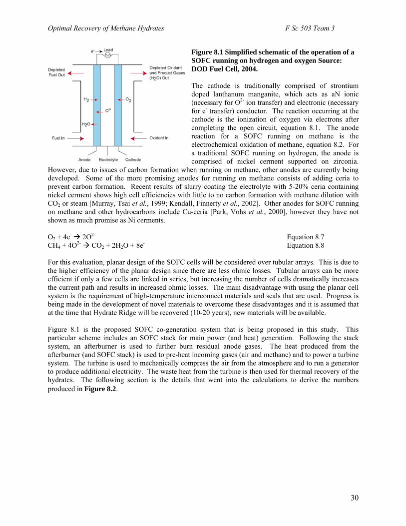
Optimal Recovery of Methane Hydrates of the Hydrate Ridge, Offshore Oregon Team 3 Prabhat Naredi; Marielle Narkiewicz; James Strohm; Uthaiporn Suriyapraphadilok; Bei Wang; Yu Zhang 30 November 2004
Transcript
Optimal Recovery of Methane Hydrates of the Hydrate Ridge, Offshore Oregon
Team 3 Prabhat Naredi; Marielle Narkiewicz; James Strohm; Uthaiporn Suriyapraphadilok; Bei Wang; Yu Zhang
30 November 2004
Optimal Recovery of Methane Hydrates F Sc 503 Team 3
Table of Contents 1. Nomenclature……………………………………………………………………. 3 2. Abstract ………………………………………………………………...……….. 4 3. Overview of Methane Hydrates…………………………………………………. 4 4. Resource Characterization of Hydrate Ridge…………………………………… 5 5. Production of Methane Hydrates 1. Depressurization……………………………………………………………. 7 2. Inhibitor Injection…………………………. ……………………………… 12 3. Thermal Stimulation. ……………………………………………………… 136. Environmental Aspects of Hydrate Ridge 1. Biological Communities and Methane Flux…......………………………… 18 2. Global Carbon Cycle…………………...……………................................... 19 3. Seafloor Stability.………………….……………………………...………... 207. Upstream Equipment and Production 1. Rig Selection and Well Completion………………………………………... 21 2. Pipeline Plug Prevention…………………………………………………… 238. Transportation of Natural Gas 1. Traditional Natural Gas Processing.……………………………………….. 24 2. Overview of all Transportation Modes…………………………………….. 24 3. Solid Transportation of Natural Gas……………………………………….. 25 4. Solid Oxide Fuel Cell System for Electricity Generation………………….. 279. Overall Economic Analysis of Hydrate Production and Utilization……………. 3210. Conclusion…………………..…………………………………………………... 3411. Works Cited………...…………………………………………………………… 3512. Appendixes.…………………………………………………………………...… 37
2
Optimal Recovery of Methane Hydrates F Sc 503 Team 3
1. Nomenclature Cp Heat capacity (J/K kg) •
m Mass flow rate
Hn Mole of methane gas
∆G Gibb’s Free Energy ∆H Enthalpy of hydrate dissociation
HΦ Volume fraction of hydrate in the core
φ Porosity
Ψ dimensionless surface roughness factor ρ Density of the porous medium including the hydrate (kg/m3) µg Viscosity of gas (cp) ρH Density of the pure methane hydrate (kg/m3) ρR Density of the porous medium (kg/m3) µw Viscosity of water (cp) ρW Density of pure water (kg/m3) adec Specific decomposing hydrate surface area per unit hydrate volume ageo Geometry surface area ∆E/R Activation energy over the gas constant (K) fg Fugacity of methane at the solid surface F Faraday’s constant FHg Mass fraction of gas in unit mass of hydrate (KgCH4/KgHydrate) fse Fugacity of methane at the three-phase equilibrium pressure k Phase permeability (mD) k Thermal conductivity of hydrate (kW/m2 K) k0 Intrinsic rate constant for decomposition (kmol/m2-kPa-s) kd Decomposition rate constant (kmol/m2-kPa-s) kgw Relative permeability with respect to gas krw Relative permeability with respect to water MWH Molecular weight of hydrate (g/mol CH4 in hydrate) p1 Initial pressure (MPa) p2 Formation pressure (MPa) pg Pressure of methane at the solid surface pG Pressure at the well (MPa) pi Initial pressure (MPa) po Wellbore pressure (MPa) pse Equilibrium pressure at the dissociation interface temperature (MPa) P Power (W) Q Heat defined as mcp∆T qs Specified heat flux at the decomposing surface (kW/m2) Ste Stefan number t Time T1 Initial gas temperature (K) T2 Final gas temperature (K) Ti Initial temperature (K) Toe, Equilibrium temperature at the wellbore pressure (K) Ts Temperature of the dissociation interface (K) X(t) Position of the dissociation interface as a function of time (m) ∆T Temperature difference between the bulk fluid and the hydrate interface ηc Efficiency of the compressor λ Solution of eq. 5.3
3
Optimal Recovery of Methane Hydrates F Sc 503 Team 3
2. Abstract Methane hydrate presents a potentially enormous amount of energy assuming technology can be developed for commercial production. The aim of the present paper is to examine the feasibility of recovery of gas hydrates from Hydrate Ridge off the coast of Oregon. In the present analysis, reservoir assessment of the hydrates, their recovery methods, safety and environmental aspects and their efficient utilization are considered. Our initial estimate indicates that recovery of gas hydrate from the Hydrate Ridge is currently uneconomical. In the present case, due to the very small volume of gas the reservoir, injection of hot brine as a recovery method and transportation of recovered gas as a gas hydrate or conversion of gas into electricity is suggested. Keywords: hydrate recovery, hydrate transportation, hydrate utilization 3. Overview of Methane Hydrates Gas hydrates are low molecular weight molecules trapped in water-ice “cages” in permafrost or sub-sea deposits, and have gained interest in the energy, safety and environmental sectors [Boatman and Peterson, 2000]. If water and methane are present, methane hydrates can form with the appropriate (high) pressure and (low) temperature in sediments that are capable of trapping methane. The hydrate can exist in three different forms, structure I, II, or H. In structure I, which is most common and is the focus of this report, the cages are arranged in body-centered packing and are large enough to include methane, ethane and other gas molecules of similar diameters [Henriet and Mienert, 1998]. Methane is the most common gas found in hydrates, comprising 99% [Boatman and Peterson, 2000], (due to the small molecular size of methane) and is the main component in natural gas. The structure of the clathrate allows methane gas to be compact. 1 ft3 of methane hydrate can hold roughly 160 ft3 of methane gas at STP [Mori and Ohnishi, 2001] giving methane hydrates an energy content of roughly 184,000 btu/ft3. As previously mentioned, methane hydrates occur in permafrost regions as well as in the ocean bottom. Over geological time, the total enclathrated methane in the oceans has grown to 2.1x10¹⁶ SCM [Sloan, 2000]. The amount of hydrated methane in the permafrost is relatively small (7.4x10¹⁴ SCM) compared to the amount trapped in the oceans [Sloan, 2000]. The methane hydrates found in sub-sea regions are primarily structure I, and of biogenic origin (formed from bacterial ingestion of organic matter). Methane from the hydrates can be used directly, converted to a synthetic fuel, burned to produce energy for methane fuel cells, transported to a point of use and transformed to hydrogen, and the list goes on [Centre and de Fontaubert, 2001]. However, at present, methane hydrate recovery is not an economical process, and is not fully understood with respect to the environment and safety of the seafloor. This report explores all characteristics of optimal methane hydrate recovery and utilization of the Hydrate Ridge, offshore Oregon.
4
Optimal Recovery of Methane Hydrates F Sc 503 Team 3
4. Resource Characterization of Hydrate Ridge Hydrate Ridge is 25 km long and 15 km wide ridge in the Cascadia accretionary complex. It is characterized by a northern ridge having a water depth of ~600 m and a southern peak with a depth of ~800 m. Hydrate Ridge appears to be capped by hydrate as indicated by a strong bottom-simulating reflector (BSR). In the present study our focus is to recover the gas hydrate from southern Hydrate Ridge. During Leg 204 on SHR, nine sites have been drilled and cored to determine the concentration and distribution of gas hydrates. Lithology at all the sites is similar, with abundant turbidities, some debris flows and several notable ash layers. A brief summary of the findings is shown in Table 4.1 below. Table 4.1 Reservoir Site Assessment of Hydrate Ridge. Region Sites Thickness
It is assumed that sediment porosity (65%) Assuming that one unit volume of hydrate will yield 164 unit volume of gas. * Saturation value chosen is
average value of all the estimation methods.
The above table does not take any available free gas into consideration, thus it was not part of this study. From the above table, it is evident that gas hydrate concentration is significantly greater beneath the summit as compared with other region. Therefore, our focus will be first on physical property estimation and optimal recovery methods from site 1249. Properties Permeability: Site 1249, spanning 300 m by 500 m, and 778 m below seafloor, is composed of clay and silty clay. This corresponds to a typical permeability of 10 md. Permeability was also estimated from capillary models [Kleinberg, Flaum et al., 2003] and is found to be 20md for 4 micrometer particle size. Density: Wet bulk density of the samples was measured in the range from 0.35 to 7.5 g/cc. Pore space was estimated from the change in sample volume before and after compression to 160000MPa. The sample shows high variability in porosity ranging from 10% to 70% and the values are negatively correlated with sample density. From this correlation, the maximum density at zero porosity was estimated to be 810kg/m3. Porosity: On a macroscopic scale the fabric varies from highly porous with soupy and mousse like textures. Leg 204 observations clearly indicate that hydrate is present in lenses and nodules. Pore Fluid Concentration: Pore fluid recovered from the upper 20 mbsf show pronounced enrichment in dissolved chloride concentration. The highest chloride concentration measured is 1368 mM in a sample collected. The degassing experiment document that methane concentration range from 200 to 6000 mM well above saturation value at in situ temperature(4.5 ºC-9 ºC) and pressure (7.9 MPa). Gamma density logs show some layers having density slightly lower than 1000kg/m3, which indicates this layers to be pure gas hydrates. In addition a low density spike
5
Optimal Recovery of Methane Hydrates F Sc 503 Team 3
(750kg/m3) in an 8 cm thick gas hydrate layer reveals the evidence of free gas within hydrate. Relatively high concentrations of propane and higher hydrocarbons at the start of core degassing
also suggest the presence of free gas. Phase Equilibrium Diagram: Since it is extremely difficult to predict the phase behavior in porous sediments, a simplified phase diagram shown left will be used for the design calculation. A brief summary of useful physical properties is mentioned in Figure 4.1 below, and will be used for the design calculation. A brief summary of useful physical properties is mentioned in the Table 4.2 below.
Table 4.2 Summary of physical prCompilation of authors listed in WorkDensity of porous medium (ρr)
operties of sediments in Hydrate Ridge. Source: s Cited Page.
Thermal conductivity of rock (Kr)
1.5 W/m k
Thermal conductivity of hydrate (Kh)
0.5 W/m k
Thermal conductivity of gas (Kg)
0.031 W/mK
Thermal conductivity of water (Kw)
0.6 W/m K
Permeability (k) 10 md
Heat of dissociation (∆Hd)
13.52 -.0042 Ti kJ/mol gas
6
Optimal Recovery of Methane Hydrates F Sc 503 Team 3
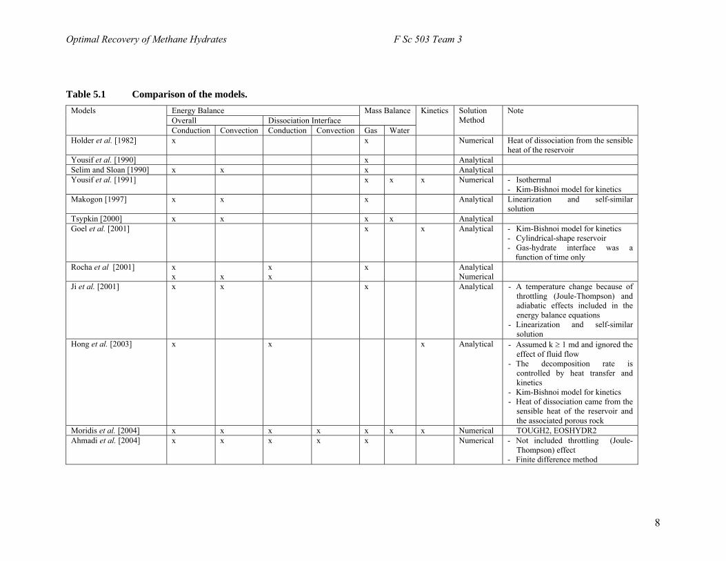
5. Production Methods of Gas Hydrates Methane can be recovered from has hydrates through modification of equilibrium conditions. Three common recovery methods employed are depressurization, inhibitor injection and thermal stimulation. The recovery method should be chosen on the basis of environmental damage as well as economics. 5.1. Depressurization When the reservoir pressure is reduced below the three phase equilibrium value, hydrate dissociates by absorbing energy from the surrounding and, hence, results in a decrease in reservoir temperature. Heat flows to the dissociating hydrate interface by thermal conduction and a thermal gradient is established. Hydrate will continue to dissociate until sufficient gas evolves to achieve the equilibrium pressure at the lower temperature. A thermal gradient has to be maintained in order to continue dissociation of the hydrate. Among all three hydrate recovery methods, the depressurization is the most energy intensive method since there is no supply of energy or any chemical into the reservoir. Three main mechanisms are involved in the depressurization of gas hydrates: fluid flow, heat transfer and kinetics. Many authors have been developing either analytical or numerical models to simulate the gas production from hydrate decomposition in porous media. The association process of these models was assumed to occur at a dissociation interface, which separates the reservoir into two zones: the gas zone near the well and the hydrate zone far away from the well. The dissociation interface moves forward into the reservoir with time. Table 5.1 briefly summarizes the features of some models in terms of mechanisms and mathematical methods used. In this work, a simple one-dimensional model from the work of Hong et al. (2003) is considered. It should be noted that this wellbore model is linear, not radial. The effect of heat transfer, intrinsic hydrate decomposition, and fluids flow are calculated independently, i.e. if considered one mechanism, the other two effects are ignored, in order to determine the rate-controlling mechanism(s). An analytical model of methane hydrate decomposition for each of above three-mechanism is presented for a semi-infinite hydrate. The physical, chemical and geological parameters from the Hydrate Ridge Leg 204 are used to simulate the effect of the three mechanisms mentioned above. Assume that there is a methane hydrate reservoir with initial pressure Pi and initial temperature Ti containing stable solid hydrate. When a well is drilled, the pressure drops to the wellbore pressure Po below the pressure-temperature equilibrium condition. The hydrate in the neighborhood of the well starts to dissociate. The dissociation process is assumed to occur only at the front of the gas and hydrate zones instead of the entire volume. At x=∞, it is assumed that the reservoir pressure and temperature are fixed at Pi and Ti, respectively. The dissociation interface, X(t), separates the reservoir into two zones. The area 0<x<X(t) is referred to as the gas zone and the area X(t)<x<∞ is the hydrate zone. The dissociation interface moves outward as the gas production from the well continues. In this work, the three phase equilibrium pressure-temperature is given by [Hong et al., 2003]:
)/94593185.49exp(10 6sse Tp −= − Equation 5.1
where Ts is in K and pse is in MPa. pse is the equilibrium pressure at the dissociation interface. Decomposition Rate Controlled by Heat Transfer To obtain the rate of decomposition by heat transfer, the effects of kinetics and fluids flow are ignored. The surrounding gas at the interface is at the thermodynamic equilibrium condition.
7
Optimal Recovery of Methane Hydrates F Sc 503 Team 3
Table 5.1 Comparison of the models. Energy Balance Overall Dissociation Interface
Mass Balance Models
Conduction
Convection Conduction Convection Gas Water
Kinetics SolutionMethod
Note
Holder et al. [1982] x x Numerical Heat of dissociation from the sensible heat of the reservoir
Yousif et al. [1990] x Analytical Selim and Sloan [1990] x x x Analytical Yousif et al. [1991] x x x Numerical - Isothermal
- Kim-Bishnoi model for kinetics Makogon [1997] x x x Analytical Linearization and self-similar
solution Tsypkin [2000] x x x x Analytical Goel et al. [2001] x x Analytical - Kim-Bishnoi model for kinetics
- Cylindrical-shape reservoir - Gas-hydrate interface was a
function of time only Rocha et al [2001] x
x x
x x
x Analytical Numerical
Ji et al. [2001] x x x Analytical - A temperature change because of throttling (Joule-Thompson) and adiabatic effects included in the energy balance equations
- Linearization and self-similar solution
Hong et al. [2003] x x x Analytical - Assumed k ≥ 1 md and ignored the effect of fluid flow
- The decomposition rate is controlled by heat transfer and kinetics
- Kim-Bishnoi model for kinetics - Heat of dissociation came from the
sensible heat of the reservoir and the associated porous rock
Moridis et al. [2004] x x x x x x x Numerical TOUGH2, EOSHYDR2Ahmadi et al. [2004] x x x x x Numerical - Not included throttling (Joule-
Thompson) effect - Finite difference method
8
Optimal Recovery of Methane Hydrates F Sc 503 Team 3
The interface temperature is at Toe, the equilibrium temperature at the wellbore pressure (po). Hence, the driving force for the heat transfer mechanism is equal to Ti-Toe. Only the heat transfer by convective is considered. The hydrate decomposition controlled by the heat flow is analogous with the melting moving boundary problem [Ozisik, 1993]. At time t = 0, the reservoir is at the temperature Ti and the dissociation interface, X(t) is at x = 0. At any time t, the temperature at X(t) is equal to the equilibrium temperature with the wellbore pressure and the temperature is equal to Ti when ∞→x . The derivation of the heat transfer equations of the system and its dissociation interface is shown elsewhere [Hong et al., 2003]. The analytical solution for the rate of moving of the hydrate interface as the hydrate decomposes is given by:
tdttdX αλ=)(
Equation 5.2
where λ is the solution of the following equation:
πλλ λ Steerfce =)(
2
Equation 5.3
and Ste is called Stefan number, which is defined as the ratio of the sensible heat of the hydrate and associate rock to the heat of decomposition:
HTTc
SteH
oeip
∆
−=
φρρ )(
Equation 5.4
where, ρ is the density of porous medium including the hydrate (kg/m3), cp is the heat capacity (kJ/kgK), and φ is the porosity. The parameters used in the study are shown in Table 5.2. Decomposition Rate Controlled by Intrinsic Kinetics At the hydrate-gas interface, the hydrate dissociation into water and gas is controlled by the kinetics of decomposition. Kim et al (1987) proposed that the hydrate decomposition rate is proportional to a driving force defined by the difference between the fugacity of methane at the three-phase equilibrium and the fugacity on methane in the bulk, and the specific decomposing hydrate surface area per unit hydrate volume (adec). Considering methane as an ideal gas, the fugacity can be simply replaced by the pressure of methane at the equilibrium pressure, , and the pressure of the bulk gas psep g. From the mass balance around the hydrate-gas interface, the relationship between the molar rate of hydrate decomposition and the location of the interface, the analytical solution for the rate of moving of the dissociation interface is given by:
)( gsedH
H ppkMdtdX
−Ψ=ρ
Equation 5.5
where is the dimensionless surface roughness factor, MΨ H is the molecular weight of hydrate (g/mol CH4 in hydrate), ρg is the pressure of methane at the solid surface (MPa), and the decomposition rate constant (kd), defined by:
RTEod ekk /−= Equation 5.6
where ko is the intrinsic rate constant for decomposition (kmol/m2-kPa-s), E is the activation energy, and R is the gas constant.
9
Optimal Recovery of Methane Hydrates F Sc 503 Team 3
The driving force is the pressure difference between equilibrium pressure ( ) at the surface and the
bulk gas pressure (p
sep
g). is the dimensionless surface roughness factor and defined as, Ψgeo
dec
aaφ
=Ψ ,
where is the specific decomposing hydrate surface area per unit hydrate volume, and adeca geo is the geometry surface area. For a simplified case, Ψ is equal to unity. Clarke and Bishnoi (2001) modified the experimental apparatus of Kim et al. (1987) and obtained the activation energy similar to that of Kim et al. (1987), however, the intrinsic rate constant is approximately 10 times smaller than that reported by Kim et al. (1987). The kinetics parameters are shown in Table 5.3. The parameters from Clarke and Bishnoi (2001) and Kim et al. (1987) are compared and shown in Figure 5.1 and the results are discussed below. Decomposition Rate Controlled by Fluid Flow The continuity equation of the water in the decomposed zone is given by Aziz and Settari (1979) [after Hong et al., 2003]. It is assumes that the change of the saturation of water with time in the decomposition zone is so slow that it can be ignored, and φ and ρ are constant. The derivation of the fluid flow equation is given elsewhere [Hong et al., 2003]. The analytical solution for the continuity equation for water flow and the mass balance around the dissociation interface is:
2/11
)1(2)(
⎥⎥⎦
⎤
⎢⎢⎣
⎡
−∆
=tF
pkkdt
tdX
HHgw
wrw
φρµρ Equation 5.7
where krw is the relative permeability with respect to water, ρw is the density of pure water (kg/m3),
, is the pressure difference between the bulk gas pressure at the interface (pog ppp −=∆ s) and the wellbore pressure (po), µw is the viscosity of water, and FHg is the mass fraction of gas in unit mass of hydrate. Decomposition Rate Controlled by Gas Flow The derivation of the decomposition rate controlled by gas is similar to those obtained from water-flow-controlled. After solving the continuity equation for the gas flow and the mass balance around the dissociation interface, one can obtain the rate of decomposition as follows:
2/11
2)(
⎥⎥⎦
⎤
⎢⎢⎣
⎡ ∆=
tFpkk
dttdX
HHgg
ggw
φρµρ
Equation 5.8
where kgw is the relative permeability with respect to gas, ρg is the density of gas, and µg is the viscosity of gas. The parameters used for the fluids flow study are shown in Table 5.4.
10
Optimal Recovery of Methane Hydrates F Sc 503 Team 3
Table 5.2 Properties of medium, pure methane hydrate, water and gas.
Parameters Medium Pure Methane Hydrate Water Gas Density (kg/m3) 2675 914.7 1000 27.6 Heat capacity (kJ/kg-K) 0.837 1.6 Thermal conductivity (k) (W/m-K) 1.5 0.5 Heat of decomposition (kJ/kg) 477 Thermal diffusivity (m2/s) 3.562x10⁻⁷ 2.293x10⁻⁷ Properties of methane hydrate in the medium
Parameters Kim et al. (1987) Clarke and Bishnoi (2001) RE /∆ (K) 9400 9752.7
0k (kmol/m2-kPa-s) 1.24x10⁵ 3.6x10⁴
Surface roughness,ψ 1 MWH (g/mol CH4 in hydrate) 119.5
Table 5.4 Parameters used in the fluid flow study.
Parameters Values Permeability, k (md) 10 Relative permeability with water, krw
0.1
Relative permeability with gas, krg 0.5 Porosity 0.6 Viscosity of water, wµ (cp) 1
Viscosity of gas, gµ (cp) 0.02
Mass fraction of gas in unit mass of hydrate, FHg (kg CH4/kg Hydrate)
0.1339
Table 5.5 Temperatures and pressures used in the models.
Parameters Values Initial temperature, Ti (K) 284 Temperature of the front surface, Ts (K)
282
Wellbore pressure, Po (MPa) 2.67 Bulk gas pressure, Pg (MPa). 4.0 Equilibrium temperature at wellbore pressure, Toe (K)
274
Equilibrium pressure of interface temperature, Pse
7.1
Driving force for heat transfer equations (eq. 5.4)
Ti-Toe
Driving force for kinetic equations (eq. 5.5)
Pse - Pg
Driving force for fluids flow equations (eqs. 5.7 and 5.8)
Pg - Po
11
Optimal Recovery of Methane Hydrates F Sc 503 Team 3
Figure 5.1 Comparison of the dissociation rate controlled by heat transfer, water flow, gas flow, and kinetics (parameters obtained from both Clarke-Bishnoi (2001) and Kim et al. (1987) are present): (a) rate of movement of dissociation interface; (b) distance of front; (c) production rate; and (d) cumulative production rate. Equations 5.2, 5.5, 5.7 and 5.8 and the parameters in Tables 5.2-5.5 are plugged into Matlab. The comparison of the dissociation rate controlled by heat transfer, water flow, gas flow, and kinetics (parameters obtained from both Clarke-Bishnoi (2001) and Kim et al. (1987) are present) is shown in Figure 5.1. The rate of moving of the dissociation interface (dX(t)/dt) and the distance of interface (X(t)) are shown in Figures
5.1(a) and 5.1(b). The production rate and the cumulative production rate are shown in Figure 5.1(c) and 5.1(d). All plots are performed over 10 years of production.
(b)(a)
(c) (d)
From Figure 5.1 (a), it can be seen that the hydrate dissociation rates obtained from fluids flow (both water flow only and gas flow only) is higher than the other two mechanisms, whereas the rate of hydrate dissociation obtained from heat transfer only is the lowest. Note that the results obtained from the kinetic model are independent of time as described by eq 5.5, Figure 5.1 (a) and Figure 5.1 (c). These results may not represent the real hydrate dissociation since the temperatures and pressures are changing all the time when the dissociation occurs. However, the results from this simple model can be used to guide that the rate of hydrate dissociation from the intrinsic kinetics only is about 1-2 order of magnitude higher than the rate obtained from the heat transfer-controlled model, and about the same order of magnitude when the kinetic parameters from Kim et al. (1987) were employed. Two kinetic parameters are shown in Figure 5.1: Clarke and Bishnoi (2001) and Kim et al. (1987). The hydrate dissociation rates obtained from Kim et al. (1987) is about one order of magnitude higher than those of Clarke and Bishnoi (2001). It is worth noting the kinetic parameters obtained from both Clarke and Bishnoi (2001) and Kim et al. (1987) were experimentally measured in a stirred tank where the mass and heat transfer resistances were eliminated by vigorous stirring. The intrinsic rate constant of decomposition in porous media may be significantly lower that obtained in the stirred tank. If this is the case, both heat transfer and kinetics are the rate limiting steps in this study. To be simple and conservative, it can be said that heat transfer is the rate limiting step for hydrate dissociation in our case. Only heat transfer effect is considered. From Figure 5.1 (a), the rate of moving of the dissociation interface is about 1 mm/day at very early of the dissociation and drops rapidly to less than 0.2 mm/day after the 4th year of production. After that, the dissociating front is slowly moving and the rate of moving is approaching 0.1 mm/day at the 10th year of production. This dissociation rate is
12
Optimal Recovery of Methane Hydrates F Sc 503 Team 3
very slow. As shown in Figure 5.1 (b) the total distance of the dissociating interface is only 1 meter at year 10! Since there is a presence of free gas zone around the BSR at Site 1249, it is assumed that after drilling the production well(s), the pressure dropped uniformly over the BSR. The dissociation front is moving upward in the BSR to seafloor direction. Hence the dissociation area is equal to the size of Site 1249, which is about 300x500 m2. The production rate is approximately 0.1 million m3 STP/yr at the beginning and drops to about 0.03 million m3 STP/yr after the first year of production. The production rate drops to about 0.01 million m3 STP/yr and the cumulative amount of gas is 1.1 million m3 STP after 10 year of production. This rate of gas production is a lot lower than our target production rate of approximately 30 million m3 STP/yr. In conclusion, the production by only depressurization is not economical in our case. With the help of hot fluid injection, this would eliminate the heat transfer effect and help enhancing the kinetics of dissociation. If the heat transfer and kinetics are no longer the rate limiting steps, we can be able to meet our target production rate. Figure 5.1 (d) shows that if the water-flow is the controlled mechanism, the cumulative amount of gas is equal to 110 million m3 STP which is approximately the amount of reserve gas in the Site 1249. 5.2. Inhibitor Injection Through injection of chemicals to the sub-sea hydrates, dissociation of the hydrate will occur. The chemical decreases the stability of the hydrate by changing the equilibrium temperature or the pressure. In the natural gas industry, alcohols (methanol) and glycols are commonly used to inhibit hydrate formation [Carroll, 2003]. The reason these chemicals are often used is that they exhibit some hydrogen bonding and therefore interfere with the hydrogen bonds of the water in the hydrates [Carroll, 2003]. Glycols are much less volatile than methanol, but glycol is usually more costly than methanol and are therefore used less often [Carroll, 2003]. Besides adding polar solvents, ionic solids can also be added to dissociate the hydrate. Although it may seem wise to inject an inhibitor to destabilize the hydrate zone, the effect to the marine life and the sea floor could be detrimental. Introducing something unnatural and foreign to a system can lead to problems. Corrosion of the pipelines may occur if air dissolves in the inhibitor [Carroll, 2003]. Both Ramya Venkataraman and Esra Eren did some computational modeling to see a difference between methanol and ethylene glycol to determine which inhibitor would be more economically and environmentally sound. They concluded that concentrations of both methanol and ethylene glycol of greater than or equal to 20% would be needed to cause dissociation. Based on a cost analysis, they found that methanol is $0.84/gallon (USD) and ethylene glycol is $4.75/gallon (USD). To dissociate the hydrate, 3.9x10⁵kd/d or 4.1x10⁵kg/d of methanol and ethylene glycol, respectively, would need to be injected. Inhibitor injection is neither environmental nor economic and thus is not a viable hydrate recovery method. 5.3. Thermal Stimulation Background The Thermal stimulation method proposes the use of a source of energy to raise the reservoir temperature, thus breaking the hydrogen bonds in the hydrate to release the gas. Methods that have been suggested in the literature are: (1) injection of hot fluid such as water, steam or brine; (2) in-situ combustion and; (3) electro-magnetic heating. In situ combustion process is basically a burning front that slowly moves from an injection well to production well. Electromagnetic heating is a process, which either uses microwave or AC current to heat the reservoir. Our main concern in this study is to evaluate the feasibility of fluid injection methods. This technique has been well characterized in the laboratory for hydrate dissociation and is traditionally used for oil and gas recovery from conventional fields. In the literature two approaches have been suggested for realization of hot fluid injection method. One approach is a single well, cyclic thermal injection model where hot water, brine or steam can be injected
13
Optimal Recovery of Methane Hydrates F Sc 503 Team 3
into the hydrate formation. In this method, hydrates are allowed to dissociate during a “soak” period and then gas and water are produced from the same well. This approach was well studied by Bayels et al. (1982) and Kamath (1987). Another method is use of multi-well, continuous thermal injection model. Hot water or brine will be injected from one well and dissociated gas will be produced from production well. Experimental and simple, conceptual modeling studies have been done for evaluation of the production using this technique by [McGuire, 1981], and Sloan et al. (1985,1990). Hydrate thermal dissociation rates were first quantified in Holder’s laboratory with the work of Kamath et al. (1987) for steady-state dissociation measurement of propane and methane hydrates using hot water as the dissociation medium. They developed an empirical correlation for dissociation rate as follows:
( ) 05.2410464.6 TAM
H
H ∆×=Φ− Equation 5.9
where MH is the steady state of hydrate dissociation (gmol/hr) HΦ is the volume fraction of hydrate in the core, A is the surface area at the interface (cm2), and T∆ is the temperature difference between the bulk fluid and the hydrate interface. In subsequent research, Kamath et al. [1987], [Sira, Patil et al., 1990] proposed to combine the thermal injection technique with inhibitors such as brine, methanol and glycol. The graph below shows a correlation for gas production as a function of the temperature difference between the bulk fluid and the hydrate interface (∆T). Selim and Sloan [1985, 1990] developed an unsteady state model for the position and temperature profile in a moving hydrate boundary. Their model can be viewed as a pseudo steady-state model after hydrate dissociation had commenced. A schematic of their model shown in Figure 5.2, indicates that hydrate dissociation occurs at a moving boundary X (t) which separates the un-dissociated hydrate region from the dissociated region. Once the temperature is exceeded, the interface will move at a decreasing velocity due to the insulating effect of increasing thickness of dissociated zone. On solving for large time, they found the following simplified solution for front velocity.
)1()(
StkTTq
dtdX iss
+−
=α
Equation 5.10
where X is the position of decomposing interface (m), Ts is the equilibrium temperature at system pressure (K), K is the thermal conductivity of the hydrate, qs is the specified heat flux at the decomposing surface (kW/m2), α is the thermal diffusivity (m2/s), and St=λ/(Cp(Ts-Ti)), where λ is the heat of dissociation kJ/mol CH4.
Our Approach STEP 1: Feasibility study of thermal stimulation by determining Energy Efficiency Ratio
Energy efficienc
inpuEnergy oEnergy EER =
increase the reshydrate. Energy shown in the Afavorable condit
Figure 5.2 Dissociation
y ratio (EER) is defined as the following:
hydrate dissociate t tohydrate fromutput Where, energy input to dissociate hydrate includes sensible energy to
ervoir temperature, to the dissociation temperature and latent heat of dissociation of output is the energy produced upon combustion of natural gas. A sample calculation is ppendix A. Our estimate indicates that the energy efficiency ratio of ~13 which is ion as a recovery method. However, the above calculation assumed that all the heat
14
Optimal Recovery of Methane Hydrates F Sc 503 Team 3
supplied goes instantaneously to heat the reservoir temperature and no heat loss is accounted in overburden/underburden heating and transmission lines. Both the assumptions are very unrealistic therefore further energy analysis is carried out to determine the feasibility. STEP 2: Selection of thermal stimulation method Since preliminary energy efficiency of thermal stimulation is good for recovery, our next objective was to determine how thermal energy can be provided to the reservoir. We considered the following options for thermal stimulation method: (1) steam injection; (2) hot water injection; (3) hot brine injection; (4) methanol/glycol injection; (5) in situ combustion; (6) geo-thermal heating; and (7) addition of compressed CO2. Each of the above mentioned methods has their own merits and disadvantages. In steam injection, heat loss in the well bore and reservoir is very high especially for thinner hydrate zone. Steam also reacts with clay and swells them which will reduce the permeability [Faure, 1998]. Another disadvantage associated with steam injection is that it will increase the water vapor in the recovered gas. Use of glycol/methanol is governed by economics because large quantity of these expensive chemicals will be required. Results of the mathematical model developed by Kamath et al. (87) (cited in [Sloan, 1998]) showed that injection of hot brine is more efficient than hot water and glycol/methanol because brine acts as a hydrate inhibitor. Brine also causes most reduction in dissociation temperature. Also as a consequence, heat of dissociation is lower at lower dissociation temperatures and therefore heat losses in pipelines are lower for brine. Geothermal heating is discarded because only at certain location are these hot reservoirs found. Even if it is present, arrays of wells need to be drilled in geothermal aquifers and sediments just below the hydrate region. Gas near the circulating hot brine will dissociate, therefore additional production wells need to be drilled which will make it very expensive process. In situ combustion process is eliminated as typically 80% of the heat generated upon combustion is wasted in heating of reservoir rock [White and Moss, 1983] STEP 3: Selection of injection scheme As shown above, hot brine seems to be the best injection fluid as a thermal stimulation medium. Our next goal was to determine the optimal injection scheme. Typically the following injection schemes are used for conventional oil and gas recovery: (1) cyclic injection; (2) continuous injection; and (3) recirculation of hot brine. Though cyclic injection has the advantage of lower heat loss in pipelines and presence of heated zone near production well, it is discarded because of the periodic nature of production, and operating time delays bringing the well to production after injection phase. Shut in period can also cause refreezing of the dissociated gas during injection. Brine recirculation is eliminated as it can heat only limited zone and a special pump is required to bring back the hot brine. Also due to very low thermal diffusivity, it is extremely inefficient process. Continuous injection of brine has the disadvantage because the dissociation front is far from the production well and it is also limited by pore fluid pressure rise upon dissociation. However, due to continuous production of gas and very low formation depth makes it a comparatively better option among the above mentioned injection scheme. STEP 4: Determination of well configuration and cost estimation of brine injection We chose continuous injection for the dissociation of hydrate due to the continuous nature of production scheme. Since we are just below the sea floor, it’s not possible to inject at higher pressures due to fracturing limitation. Therefore, first we calculated the fracturing pressure using the Hubbert and Willis method [Bourgoyne, Chenevert et al., 1991] mentioned below.
( ) 3/2 fobff PP += σ Equation 5.11 where Pff is the fracture pressure, Pf is the pore fluid pressure, and σob is the overburden stress. Using the property data for site 1249, we estimated that our fracturing pressure is 9 MPa. Therefore our pressure at the injection well is kept at 9 MPa and pressure at the production well is kept just below the 8 MPa. Our next objective was to determine the optimal well spacing we can keep. Typically in industry, 2-5 acre well spacing design and 1 foot well bore diameter is chosen [White and Moss, 1983]. Using the
15
Optimal Recovery of Methane Hydrates F Sc 503 Team 3
standard reservoir engineering techniques [Economides and Nolte, 2000] we calculated the injection rate using following formula.
)))/ln(/(2)(( wwfw rrkhPPq µΠ−= Equation 5.12 where q is the fluid injection rate, Pw is the injection pressure, Pwf is the wellbore pressure (8MPa), h is the thickness of the gas hydrate zone (m), r is the well spacing, and rw is the wellbore diameter. Once calculating the injection rate for particular well spacing (r), we calculated the rate of dissociation by assuming that upon injection, all the pore fluid is instantaneously mixed and comes at dissociation temperature. Rate of front movement is determined by locating the temperature front which lags behind the injection front by factor R which can be determined using following formula [Elsworth, 2004].
⎟⎟⎠
⎞⎜⎜⎝
⎛
Φ
Φ−+Φ=
ff
rrff
CPCPCP
Rρ
ρρ )1( Equation 5.13
where ρ is the density of fluid, CPf is the fluid heat capacity, CPr is the rock heat capacity, and Φ is the porosity of the medium. The above ratio R was computed without accounting for any heat of dissociation, which can be significantly different since ∆HD is approximately 10 times higher than sensible heat requirement of hydrate. Using the property data from Table 4.2 for site 1249, we estimated the value of R to be 1.64. Then we calculated the lifetime of the reservoir by assuming that our total available injection volume is the volume occupied by hydrate. The assumptions of the model are as follows: instantaneous rate of hydrate dissociation; no effect of fluid flow; and permeability is sufficient for continuous fluid injection. A sample calculation is presented in the Appendix B and result is shown in the diagram below.
Determination of Well Spacing
0
20
40
60
80
100
120
140
1 2 3 4 5Drainage radius(*20m)
Num
ber o
f wel
ls
0.00E+00
2.00E+01
4.00E+01
6.00E+01
8.00E+01
1.00E+02
1.20E+02
1.40E+02
1.60E+02
1.80E+02
2.00E+02
Prod
uctio
n ra
te(B
CF/
yr)
Number of wellsProduction rate
Figure 5.3 Plot used to determine optimal well spacing. The above diagram can be used to determine the optimal well spacing. We chose well spacing to be 100 m as lower spacing results in more injection well. At this well spacing , production rate is 5.27 bcf/ year, production life time is 3.3 years and number of injection well is ~5. Once knowing the injection rate, we can determine the required injection temperature using following energy balance.
16
Optimal Recovery of Methane Hydrates F Sc 503 Team 3
( )⎟⎟⎠
⎞⎜⎜⎝
⎛Φ
Φ∆+−+=
bbh
hdisees CpSV
SVHTTVCpTT
ρρ )()(
Equation 5.14
where Ts is the dissociation temperature, ρe is the volume of influence at any time, Cpe is the effective specific heat of the system, Sh is the hydrate saturation factor, ρb is the brine density, and Cpb is the brine specific heat. We estimated injection temperature to be 525ºC at 9MPa which is very high value as we assumed that heat is provided by only the available injection volume for hot brine. STEP 5: Effect of heat loss on EER In the above analysis, heat loss in the pipe line and loss due to overburden and under burden formation is not considered. Assuming constant sea temperature of 10ºC throughout the sea, we determined transmission line heat loss by using following formula.
TUAQ ∆= Equation 5.15 Where, overall heat transfer coefficient U is determined by evaluating the various resistances to heat flow.
1
0
lnln−
⎥⎥⎥
⎦
⎤
⎢⎢⎢
⎣
⎡
+++=hr
rK
rrr
Kr
rr
hrr
Uto
i
i
to
ii
t
ti
toto
iti
to Equation 5.16
where rto is the outside tube diameter, rii is the inside tube diameter, hi is the inside heat transfer coefficient, Kt is the tube thermal conductivity, ri is the insulation diameter, Ki is the insulation thermal conductivity, and h0 is the outside heat transfer coefficient. For the property data mentioned in the Table 4.2, we estimated the total heat loss in the pipe line to be 5.66 E+10 kJ. Usually major source of heat loss is due to under-burden and overburden strata. In our case, overburden is sea water. This can be calculated using following formula [White and Moss, 1983].
( )dt
tTTK
tTTK
AQifelt
r
usr
w
oswl ∫
⎥⎥⎦
⎤
⎢⎢⎣
⎡
Π
−+
Π
−=
0
)()αα
Equation 5.17
where Ql is the heat loss to overburden/underburden stress, Kw is the water thermal conductivity, and Kr is the rock thermal conductivity. The above equation is determined by the transient heat conduction equation in vertical direction. In our analysis we assumed the underburden sediment to be at 10ºC. Our estimation indicates that heat loss to the overburden/under burden is ~2.15 E+10 kJ. Thus energy loss in pipeline and overburden/underburden is very insignificant compared with Energy input. A sample calculation is presented in the Appendix B. STEP 6: Determine the applicability of thermal method if hydrate saturation is low In our preliminary analysis we didn’t consider dissociating the hydrate from the location where hydrate saturation is very low. In order to quantify the energy requirement, we extended our analysis to all the sites on Hydrate Ridge. Our estimate for 3% hydrate saturation which shows that energy efficiency ratio is only ~4-5 without including any heat loss. Therefore, thermal injection is not a viable option for dissociation of hydrate from other locations.
17
Optimal Recovery of Methane Hydrates F Sc 503 Team 3
6. Environmental Aspects of Hydrate Ridge 6.1. Biological Communities and Methane Hydrates If methane hydrates are recovered, there are some environmental problems that may occur. The methane hydrates serve as a food source, both directly and indirectly to the marine life. The recovery of methane hydrates will directly affect organisms called ice worms. These organisms are one to two inch long polychaete worms that can be found living in and on the hydrates (see Figure 6.1). A Penn State biologist, Dr. Charles Fisher, first found the ice worms in the hydrocarbon seeps of the Gulf of Mexico. These ice worms live in symbiosis with bacteria that feed off the methane hydrates. Both sulfide and methane are excellent bacterial substrates and the working hypothesis is that the polychaetes obtain the bulk of their nutrition by consuming free living bacteria that colonize the surface of the hydrate [Fisher, MacDonald et al., 2000]. Fisher et al.. [2000] went on to say that the worms contribute to the growth of bacteria, as well as to the hydrate’s decomposition, by creating water currents on the hydrate surface with their parapodia. The ice worms do not seem to be a food source for any organisms and are the only organisms that would be directly affected if the hydrates are removed, because these ice worms burrow into the hydrate. Therefore, the hydrate not only acts as a food source, but also a home to these organisms. Other organisms that live indirectly off the methane hydrates are tubeworms, mussels, and the food chain that follows. The primary producers in these communities are bacteria that can subsist by
using the chemical energy contained in compounds like methane and hydrogen sulfide, which are produced by seepage [MacDonald and Joye, 1997]. To live and gsymbionts neetheir blood to
tubeworms and mussels are only indirectly aforganisms can double as filter-feeders, and thuhydrates. The Hydrate Ridge off the coast of Oreare found in mounds several meters in diameter aof the filamentous sulfur-oxidizing bacteria BegRidge, four different geobiological settings are diof extensive bacterial mats in patches of 1-25m25m2; and (4) background sediments which mAcharax at depths below 5-30cm depending on thTorres et al.. [2002] studied the flux at three of tsites of methane gas ebullition, where the bulvelocities reach 1 m/s, where the methane fluxmmol/m2d. The second province is characterizedsediments capped with methane hydrate crustsestimated to be between 30 and 90 mmol/m2d. Vesicomyidae clams, where the methane flux f[Torres, McManus et al., 2002].
Studying the flux of methane in these sensitive extensive biological communities, and where theseveral methods of recovery (depressurization, injection may be the most environmentally frienmay have a chance of not altering the environmassociation of salt and hydrocarbon systems resu[NETL, 2004]. Upon reaching the surface, the
Figure 6.1 Ice worms are pink polychaete organisms found on hydratesSource: MacDonald 2000.
row, the tubeworms take up the dissolved gases their d from the water and transport the chemicals through their symbionts [Fisher, 2004]. The reason that the fected by the removal of hydrates is because these s can rely on other sources of food than the methane gon is one site where gas hydrates occur. The hydrates
nd up to 2m high, and are covered by sediment and mats giatoa [Sahling, Rickert et al., 2002]. At the Hydrate stinguished: (1) areas of discrete gas discharge; (2) areas 2; (3) areas with clam fields of a few square meters to ay contain the chemosynthetic sulfide-oxidizing clam e distance from the vent sites [Boetius and Suess, 2004]. hose sites. The first province is represented by discrete k of the flow occurs through channels in which gas for the gas discharge sites was estimated to be 106 by the presence of extensive bacterial mats that overlay , where the methane flux for the bacterial mats was The third province is represented by sites colonized by or the clam sites was estimated to be 0.45 mmol/m2d
areas can give us both a sense of where there might be largest methane reserves might be to recover. Of the thermal stimulation, and inhibitor injection), inhibitor dly. Through the injection of brine as an inhibitor, we ent drastically, and sustaining the sea life. The close lts in frequent co-migration of brine and hydrocarbons co-migration of these fluids creates distinct extreme
18
Optimal Recovery of Methane Hydrates F Sc 503 Team 3
environments capable of supporting prolific microbial communities and complex chemosynthetically based food webs [NETL, 2004]. The ability for the brine to sustain the marine life is dependent on the salinity of the brine injected. The brine pools are puddles of salt water 60 meters wide and larger that collect in sea-floor depressions and are five times saltier than surrounding seawater [Siegel, 2001].
Communities of ice worms (Hesiocaeca methanicola), bacterial mats (Beggiatoa), clams (Calyptogena pacifica and Acharax), and other fauna are associated with seafloor hydrates and methane vents on Hydrate Ridge [Tréhu, Bohrmann et al., 2003] as can be seen in Figure 6.2. The bacteria that live in symbiosis with these organisms are the base of the food chain. After speaking with several biologists at the Penn State Biology Department (Fisher Deep Sea Lab), I
realize that there is not enough information Figure 6.2 Areas of methane flux and the organisms associated with them Source: Tréhu, 2004.
linking the bacteria to hydrate recovery. Not enough is known to determine exactly what would happen if the methane hydrates were
extracted from the sea floor. If we decide to drill using the brine injection method, and if the methane is extracted safely, then perhaps life can be sustained with little to no damage to the sea life. Cores taken from site 1249 of the Hydrate Ridge have shown that pore water salinity of 105 g/kg [Milkov, Dickens et al., 2004]. Since we are interested in only recovering methane hydrates from Site 1249, if we inject a brine solution that is greater than 105 g kg-1 then our biology should be sustained and our hydrate recovered successfully. 6.2. The Global Carbon Cycle Greenhouse Gas Emissions from Methane Methane is a greenhouse gas that remains in the atmosphere for approximately 9-15 years, and is 20 times more effective in trapping heat in the atmosphere than carbon dioxide over a 100-year period. This was based on the GWP (GWP for a particular greenhouse gas is the ratio of heat trapped by one unit mass of the greenhouse gas to that of one unit mass of CO2 over a specified time period.). Once methane is emitted to the atmosphere, methane can absorb infrared radiation and redirect it back to the earth’s surface, warming it up. Methane comes from both natural and anthropogenic sources. Human emissions include landfills, natural gas systems, enteric fermentation, coal mining, manure management, wastewater treatment, petroleum systems, rice cultivation, and stationary sources. In the US, the largest source of methane emissions is landfill waste. The amount of methane emitted from these sources is estimated to be 28434 Gigagrams (Gg) from the year 2002 [EPA, 2004]. Certain natural processes can also be sources of methane emission. Some of the natural methane sources are termites, oceans, wetlands and hydrates. It is estimated that the natural emission of methane is around 1.9x10⁵Gg annually [EPA, 2004]. Methane hydrates contain isotopically light organic carbon that was once formed in sediment. Essentially, methane hydrates are “storing” a frozen greenhouse gas; therefore, if released quickly, could potentially increase the globe’s climate. Currently, the amount of methane carbon which is stored as gas hydrate in the shallow sedimentary sections along the world’s continental margins is estimated to be 25% of the amount of dissolved inorganic carbon in the ocean, and ~104 times the amount of methane carbon in the atmosphere [Paull, Brewer et al., 2003]. It is estimated that wetlands are the major source of natural emission of methane, accounting for 1.45x10⁵Gg annually. Termites are the next largest source of methane emissions, accounting for 0.2x10⁵Gg per year. Methane is produced in termites as part of their normal digestive process, and the amount generated varies among different species [EPA, 2004]. Roughly 8% (0.15x10⁵Gg) of methane emissions from natural sources
19
Optimal Recovery of Methane Hydrates F Sc 503 Team 3
comes from the oceans per year. Finally, hydrates account for approximately 5%, or 10000Gg, of methane per year. Role of Hydrates in the Global Carbon Cycle Global emissions from methane hydrates are estimated to be around 10000Gg of methane per year [EPA, 2004] Overall, the amount of methane stored in these hydrates globally is estimated to be very large with the potential of large releases of methane if there are significant breakdowns in the stability of the deposits [EPA, 2004]. Methane is an important trace component of the atmosphere, having a concentration of about 6.9x10¹²m3, and the amount of methane that is present in gas hydrates onshore and offshore is perhaps 3000 times the amount in the present atmosphere; an instantaneous release of methane from this source could have an impact on atmospheric composition and thus on the radiative properties of the atmosphere that affect global climate [Kvenvolden, 1999]. Slow release is not as harmful as an instantaneous release, because slowly released methane can be oxidized by microbial processes in the water column and become carbon dioxide. The oceans would then act as a sink for that carbon dioxide [Kvenvolden, 1999]. The fate of methane’s role in the global carbon cycle depends on the rate of methane released from the hydrates. If a marine slump or a failure occurs during production and all the methane hydrate dissociates at once, the amount that could potentially be released to the atmosphere in a worst-case scenario can be calculated as follows:
Ggkgxmassmx
mmkg
mkgd
Vmd
mx
1091009.11052.1
718.0
718.0methane of )(density
1250 and 1249 Sitesin gas methane of (V) volume1052.1
8
383
3
38
==
=
== Equation 6.1
From this estimate, quick release during our production of gas hydrates at the Hydrate Ridge would be a minimal addition to the overall methane emissions from both anthropogenic and natural sources annually. Paull et al., (2003) also estimate that release of methane from dissociation of hydrates would be a small role in the global carbon cycle. A relatively small [seafloor] slide may cut into the bottom to a depth of 10m and involve 1km2 of seafloor area [Paull, Brewer et al., 2003]. Paull et al., (2003) estimate 2.2x10⁹ mol of methane would be released from a slide like this. That estimate is approximately 3.52x10¹⁰g (or 35.2Gg) of methane released, also a small amount. The concern for the role of methane in the global carbon cycle follows a theory postulated by Paull et al., (1991) [theory cited in Kvenvolden, 1999]. In this theory, the hydrate dissociates during a falling sea level, resulting in a reduction of pressure causing more gas to dissociate. This released methane then causes global warming. Any methane released that may contribute to the global carbon cycle, will thus depend on the rate at which it is released. 6.3. Seafloor Stability and Methane Hydrates Some facts about gas hydrates at the southern summit of Hydrate Ridge are observed: (1) the high porous fabric of gas hydrates makes the bulk density (0.4 g/cm3 and 0.7 g/cm3) considerably lower than that of pure hydrates (0.91 g/cm3) [Paull and Dillon, 2001]; (2) the periodic release of pieces of porous gas hydrates results in morphology of depressions at the southern peak of Hydrate Ridge [Tréhu, Torres et al., 1999]; (3) vigorous streams of methane bubbles emanate from the sea floor [Tréhu, Bohrmann et al., 2003]. All of the above facts bring adverse impacts on the sea floor stability at Hydrate Ridge. However, Tohidi et al., (2001) indicated that gas hydrates tend to form in the center of the pore instead of adhering the wall of the pore [Tohidi, Anderson et al., 2001]. Thus, gas hydrates can have a significant cementing effect only with high saturation. Considering the low saturation of gas hydrates at Hydrate Ridge,
20
Optimal Recovery of Methane Hydrates F Sc 503 Team 3
the cementing effect of methane hydrates on sediments may be small. Therefore, in our analysis, we would assume that the seafloor will be stable upon dissociation of hydrates.
21
Optimal Recovery of Methane Hydrates F Sc 503 Team 3
7. Upstream Equipment and Production 7.1 Rig Selection and Well Completion Rig Selection There are two major classifications of marine rigs: Floating rigs and Bottom Supported Rigs. The maximum water depth ratings and cost for specific rigs are shown in the following table [Adams, 1985].
Table 7.1 Marine rigs working range Source: Adams, 1985.
Floating Rigs Bottom Supported rigs Type Semisubmersible Drilling ship Tension Leg
Platform Jackup Platform Submersible
Maximum Operation Water Depth (ft)
Not restricted Not restricted
10,000 250-350 1,000 130
Since the water depth for site 1249 is 775m (2542.62 ft) and the water depth for Hydrate Ridge is 700-1000m, only floating rigs from the above table can be used. The tension leg platform (TLP) is a platform tethered to the seabed with steel pipes. A floating superstructure carrying all operational facilities supports its own weight and applies stabilizing upward tension to relatively lightweight tubular fixed legs. Semisubmersible drilling rig is a special designed vessel used exclusively in petroleum operations. The primary advantage of Semisubmersible is stability. Drillships use a ship-type vessel as the primary structure to support the rig. Since TLP needs to be installed on site and removing is expensive, and Semisubmersible and drilling ship will be our focus. Since drilling ship is more expensive than Semisubmersible at the same water depth, we will choose Semisubmersible as our drilling rig. Sub-sea templates will be used as drilling method in our project. In this approach, several wells will be connected together on one subsea template on the sea floor. And then we will use directional drilling method to drill wells. Well Completion Basically there are two methods of completing a well, openhole where casing is set on top of the producing interval and perforating casing, where casing is cemented through the producing interval and communication is established by perforating. Openhole completions are used where there is only one zone which is either very well consolidated or provided with openhole gravel packing for sand control. This is valid as long as there are no interface problems [Perrin, 1999]. Since there are two gas hydrates zones and gas hydrates dissociation will produce gas-water interface on site 1249, openhole completion method will not be used in this methane hydrates recovery production. Perforating casing will be selected as the completion method we use. According to the water depth on site 1249, floating production system will be selected in this project. The design condition is as follows:
22
Optimal Recovery of Methane Hydrates F Sc 503 Team 3
Table 7.2 Design conditions.
Functions of several different floating production systems are shown on the following table: Table 7.3 Functions of production systems Source: Mikarri, 1977. System Function
TLP SPAR FPS FPSO
Wellhead Surface Surface Susea Subsea Export System Pipeline or
FSO+Shuttle
Pipeline or FSO+Shuttle
Pipeline or FSO+Shuttle
Shuttle
Drilling/Workover Installed Installed Installed Difficult Production Riser Rigid Rigid Flexible Flexible Storage of Oil Impossible Available Very Difficult Available Well Number Large large Not Large Not Large Development Schedule
Long Long Short Short
Reuse of Structure Not Easy Not Easy Easy Easy “FPSO” stands for Floating Production, Storage and Offloading. An FPSO system is an offshore production facility that is typically ship-shaped and stores crude oil/gas in tanks located in the hull of the vessel. Production spar consists of a large diameter single vertical cylinder supporting a deck. It has a typical fixed platform topside (surface deck with drilling and production equipment), three risers (production, drilling, and export), and a hull which is moored using a taut caternary system of 6-20 lines anchored into the seafloor. Production spars are usually used in ultra deep water with high capacity and the cost for a spar is very expensive. Considering the water depth in our project, both TLP and FPSO are more cost effective than a production spar. In water depth less than 900m and small well numbers, TLP loses its economic advantage compared to FPSO. In this project, since our well number is not very large and the water depth is 775m, FPSO production system is selected for the gas hydrate recovery. We will use a Semisubmersible to drill wells and then use the FPSO as our production system. A typical FPSO production is shown in Figure 7.1. Figure 7.1 FPSO production system schematic Source: [Mikami and Wahab, 1997]
The production system configuration will be as follows:
Item Water Depth ft 2542.62 Gas Production rate (MMCF/year)
1,000
Reservoir Depth (mbsf) 1-30, 30-90 Well Number 20 Target Recovery Amount (MMCF) 20,000
23
Optimal Recovery of Methane Hydrates F Sc 503 Team 3
(3) Total number of production wells is 16, while the number of injection wells is 4. (4) Flexible riser: diameter for production and injection riser: 6” (5) Both production well and injection wells are directional wells. (6) Each of the sub-sea templates has 5 well slots. (7) The storage capacity of FPSO will be the total amount of production possible within 10 days. (8) Wellheads for FPSO sub-sea templates are wet type.
Since our gas production rate is only 2.74 MMCF/D, most FPSO has enough capacity to meet this production rate. Here we select the FPSO with 120000 bpd capacity. The following cost estimation will be made about the production system: (Table 7.4 and Table 7.5). Table 7.4 Cost estimation of production system.
** Calculated based on data: 359 MM$ with 31 wells, 6 templates 1200m water depth from [Mikami, 1997] 7.2 Safety of Production Site Hydrate Formation in the Production and Transportation Lines Hydrates may form and can cause safety problems and costly production stoppage. Laboratory data [Lysne, 1995] suggest that hydrates formed are very porous (from 33% to 84%). Hydrates can form either single or multiple plugs. High differential pressure can trap between plugs. Hydrate Formation Prevention Method A. Hydrate control through depressurization: The fundamental purpose of depressurization is to decrease the pressure at the hydrate interface, so that the hydrate equilibrium temperature gradient from the surroundings causes heat input and hydrate dissociation [Sloan, 1998]. The pressure should be reduced as quickly as possible to atmospheric temperature on both ends of the plug. B. Hydrate formation control through thermodynamic inhibition chemicals Thermodynamic inhibitors (typically methanol and monoethylene glycol) are injected into processing lines to control hydrate formation by breaking hydrate hydrogen bonds [Sloan, 1998].
24
Optimal Recovery of Methane Hydrates F Sc 503 Team 3
C. Hydrate formation prevention through insulation There are three categories of insulation pipelines: (1) nonjacketed; (2) PIP; and (3) bundle flowlines. To achieve a desired heat transfer coefficient of 0.3 Btu/ hr-ft2- ºF, a nonjacketed system cost $1.5 million/mile, cost of bundled lines system is 1.5-2 million /mile. Depressurization method is often used to remedy the hydrate plug after the plug has formed. There is no practical utilization for this method in hydrate formation prevention. Considering that the production duration for our project is 20 years, the hydrate formation prevention through insulation is more economical.
25
Optimal Recovery of Methane Hydrates F Sc 503 Team 3
8. Natural gas transportation 8.1 Traditional Natural Gas Processing and Pretreatment The traditional natural gas processing includes dehydration, sweetening, hydrocarbon liquids recovery, and odorization. Water is a common impurity in gas streams. Water removal is necessary to prevent condensation and formation of gas hydrates. Liquid water accelerates corrosion, especially with the any present CO2 and H2S. The common choice is using glycols, because of the low costs of them. The cheaper chemical, ethylene glycol, costs $86/day and the more expensive chemical, triethylene glycol, costs $147/day. Sweetening is used to remove acid gases, CO2 and H2S. Due to its low operating cost and large amounts of acid gas removal, sweetening method by using amine became popular in natural gas processing. For the product amount with 3MMscf, the capital cost will be $1500, 000~2250, 000/day. The hydrocarbon liquids are heavier than methane, like C3 or C4. It may be necessary to separate these hydrocarbons to avoid the formation of a liquid phase during transportation. Due to its small amounts, hydrocarbon liquid recovery will be ignored. Odorization is used to determine the leaks from the pipeline for safety concern. The major odorants are mercaptans. Since we have only 0.03% CO2 and negligible amount H2S we will not have any of the afore mentioned processing requirements. 8.2 Overview of Natural Gas Transportation Modes Natural gas transportation is generally faced with several options for delivery of the recovered gas to the market, but options are quickly eliminated by reserve properties. The selection of the mode of transportation of off-shore gas is based on several factors including: (1) the distance to the coast (and/or distribution terminals); (2) size of the reserve; (3) production rate; (4) depth of reserve; (5) severity of oceanic conditions at reserve location (and pathway to distribution); (6) gas composition and processing options; and (7) type of distribution market. The various methods of transportation are briefly described below. Based on innovative techniques and economics, this paper focuses on transportation of natural gas as hydrates, and the use of solid oxide fuel cell systems for electricity generation of natural gas. Pipelines Currently on the west coast, there is a natural gas distribution network available that can deliver the recovered hydrates to the market. More extensive pipeline networks are currently being planned and/or under construction. Pipeline transportation is generally more effective for reserves that are located within 1000km from the cost and not in deep waters. Typical capital costs for the pipeline only is $80k per in-mile. Pipeline transportation as of now can be ruled out due to the high degree or processing required, low production rates, and low reserve volumes that cannot recover the initial capital costs. Compressed Natural Gas (CNG) One main disadvantage with CNG carriers is the weight of gas to weight of storage ratios. The cost for one transportation vessel is approximately $125 million for a 320 MMcf capacity tanker [Corp., 1998]]. Similar to pipeline transportation, extensive processing of the recovered gas is required for transportation via CNG. Due to the possible formation of hydrates all moisture must be removed by dehydration. CNG has a higher capital cost when compared to pipeline transportation. One advantage over pipeline transportation is that CNG transportation does not require a permanent infrastructure. However due to the high degree of processing, CNG can be ruled out and will no longer be considered. Liquefied Natural Gas (LNG) LNG is the most common way to ship large quantities of gas over very large distances. The major cost for transportation is a regasification plant. Currently there are no regasification plants on the west coast and the capital costs to build a new regasification plant are approximately $4 billion. Needless to say, unless there is a high demand for LNG shipping on the west coast, the reserve amount at the Hydrate Ridge site is unable to cover the large capital costs involved with regasification, and thus will not be the focus of this report.
26
Optimal Recovery of Methane Hydrates F Sc 503 Team 3
Gas to Liquid Technology (GTL) GTL is another transportation option available to the Hydrate Ridge site. If the natural gas is converted to methanol, DME or F-T synthetic crudes, the transportation of these liquids is the same. The advantage in terms of transportation lays in the low capital costs of transportation vessels, storage and existing infrastructure. The disadvantage of GTL technologies is the processing costs to produce the liquids. Based on some preliminary production rate economics, only ~$27,000/day of natural gas is recovered making FT-GTL technologies uneconomical. 8.3 Solid Transportation of Natural Gas The transportation method that is most economic and feasible, given the distance and amount of gas that can be recovered from Sites 1249 and 1250 of the Hydrate Ridge, is to store and transport the gas as a solid. Natural Gas Hydrate technology (NGH) was originally developed by Gudmundsson et al., in the early 1990’s, and thus is a fairly new technique for natural gas storage and transport. This method of transportation was implemented as an efficient and economic solution for gas reserves that are small to medium in annual volumes and moderate distances from the coast. Pipelines, as a transportation method, are readily used for distances less than 1000km and large volumes, while liquid natural gas transportation (LNG) is used for much larger distances [Gudmundsson and Graff, 2003]. We will employ a combination of two models for the Hydrate Ridge: Gudmundsson’s original model of hydrate formation and transportation conditions, combined with Shirota’s technique of transportation of hydrate blocks rather than pellets. Hydrate Formation After the methane is recovered from the seafloor, hydrate formation will begin. For hydrate formation the necessary pressure is 3Mpa at a temperature of 0°C or less. The gas from recovery is compressed and cooled. Based on our thermal stimulation model, we will produce 1.8bcf/year (and a total of 10bcf). This translates to approximately 5.10x10⁷m3/year, or 1.40x10⁵m3/day of gas. The gas is given to us at 2MPa and 10°C. This gas must be compressed to 3MPa for hydrate formation, storage and transport. The work needed for compression is as follows:
dJxW
MPaMPamxMPaW
MPapmxVMPapppVpW
/1085942
)2()3(4.11
)104.1()2(
3;104.1;2 1.4; 1
6
4.114.1
4.114.1354.1
1
235
11
1
1
1
21
1
1
−=
⎥⎥⎦
⎤
⎢⎢⎣
⎡−
−=
====⎥⎦⎤
⎢⎣⎡ −
−=
−−
−−
γγ
γγ
γγγ
Equation 8.1
where p1 is the initial pressure, p2 is the formation pressure, and γ is the ratio of constant pressure heat capacity to constant volume heat capacity.
As the gas compresses to 3MPa, the temperature will increase from 283K (10°C) to 318K (45°C) (see the calculation below).
KMPaMPaKT
MPapMPapKTpp
TT
31832)283(
1.0 ;2 ;283 ;4.1
4.14.11
2
211
1
2
112
=⎟⎠⎞
⎜⎝⎛=
====⎟⎟⎠
⎞⎜⎜⎝
⎛=
−
−
γγγ Equation 8.2
where T1 is the initial temperature and T2 is the final temperature.
27
Optimal Recovery of Methane Hydrates F Sc 503 Team 3
For hydrate formation this temperature must be reduced to 253K (-20°C). The following equation is used to calculate how much energy will be needed to decrease the temperature from 318K to 253K (-20°C). The performance of refrigeration is expressed as the seasonal energy efficiency ratio (SEER): SEER=Q/P, where Q= mCp∆T. If the standard value of SEER for a pump is 10 then the power needed to cool the gas to 253K can be calculated as follows:
WxPPowerWP
kJBTUKkgKkJhrkgxKTkgKkJCp
kgxmP
TmCpPQSEER
6
3
3
10349.1)()(
)055.1/1)(65)(/25.52)(/1019.4(10
65gas; of /25.52
hour;per gas of 1019.4)( mass
−=
−=
−=∆=
=∆
==
Equation 8.3
The gas then moves to a reactor vessel, and pressurized water droplets are added to the gas. For hydrate formation every 1m3 of solid must have 0.8m3 of water added to it. As the water is added to the gas, it must be simultaneously cooled to 273K for hydrate formation. Because there is approximately 160m3 of gas per every 1m3 of solid, we can say that 1 volume of water must have approximately 200 volumes of gas; therefore, if we have 1.4x10⁵m3/d of gas, then we will need 700m3/d of water for hydrate formation. The water we will use will be seawater that has been desalinated. Capital cost for a reverse osmosis desalination plant of a 700m3 water production is $646,800 ($924/m3/d). We would only need to use this system once, as our water will be recycled for hydrate production. This hydrate is in powder form and is then agglomerated to form hydrate blocks ready for transportation. Before transporting the blocks are sprayed with water to form an ice shell around the block.
Transportation and Storage Conditions Once the hydrate blocks are formed, the next step to consider is transporting the hydrates to the coast of Oregon. Because we can only produce approximately 1.40x10⁵m3/d of gas, we can only transport 875m3/d (or 3.19x10⁵m3/year) of solid hydrate (based on the gas to solid volume ratio of 160:1). The frozen hydrate is transported at 3MPa and -20°C in large bulk carriers to market, where the hydrate is melted and the natural gas recovered [Gudmundsson and Graff, 2003]. The design for our transportation carrier was taken from Mitsui Engineering and Shipbuilding Company [TheNavalArchitect, 2003]. Their vessel is a double hull dry bulk carrier with insulated holds and would have cargo capacity of 155,000m3, a length of 300m, width of 46m, depth of 13.5m, and would travel at 17knots (8.74m/s). The hydrates we will be transporting remain metastable for approximately 10 days at atmospheric pressure and a temperature of -20°C without high dissociation. Assuming a buffer of 8 days of metastability, our cargo capacity should be approximately 7500m3. This is roughly 20 times less than the cargo space for the MES ship. To account for this difference, we will also make the length of our ship 20 times smaller (15m long). Because our vessel is smaller, we also assume it to travel slower than the MES ship. Our speed is set at a maximum of 15 knots (7.72m/s). We anticipate having two ships both capable of transport and storage of gas hydrates, to be sure that if one ship is transporting hydrates, another ship is able to store any hydrates that are produced while the other ship is en route to the coast. If our estimated amount of methane hydrate is 875m3/d the calculation of how long the trip from Site 1249 and 1250 to the coast of Oregon, would take would be as follows: 875m3/d solid; if our ship can carry our produced 7000m3 of solid (per 8 days) then it would take approximately: (3.19x10⁵m3solid)(1 trip/7000m3solid)= (46 trips)/(2ships)= 23 trips per year per carrier. Equation 8.4 Dissociation When the hydrate reaches the coast, it can then be heated to dissociate the gas. Lee et al.., (2001) have reported that the energy is required to dissociate hydrates typically 50 kJ/mol for methane. The reaction can be described like below.
28
Optimal Recovery of Methane Hydrates F Sc 503 Team 3
( ) ( ) molkJgCHsCH /5044 −→ With an amount of 1.4x10⁵m3 of gas per day, and assuming $0.05/kWhr we can calculate the cost of dissociation as follows:
Economic Analysis Our total capital cost analysis for hydrate storage and transportation was based on Gudmundsson et al., (1998), who recorded their cost breakdown as 44% production ($198 million per 100MMscf); 39% carrier ($176 million); and 17% regasification all on a per day basis. To accommodate our production rate (1.4x10⁵m3/d), we must alter the calculation as follows:
productionfor cost capital 107.9$ /104.1/1083.210198
)/(100 1083.210198$
635
366
366
xxdmxdmx
xx
dMMscf/dmxx
==
→ Equation 8.6
With production holding 44% of cost, we can calculate the total capital cost:
system totalofcost capital 102.2$ %100%44
107.9 76
xxxx==
If 39% is devoted to the carrier, then approximately $8.6x10⁶ will be the capital cost of one carrier. The dissociation cost was calculated above on a per day basis; however, using Gundmundsson’s work, if 17% of the total cost is devoted to regasification, then approximately $3.7x10⁶ is the capital cost for regasification. 8.4 Solid Oxide Fuel Cell System for Electricity Generation Growing environmental concerns has resurrected the interest in fuel cells for providing more efficient and cleaner energy production. There are numerous types of fuel cells that are currently being researched or sold for energy production from various fuels. Solid oxide fuel cells (SOFC) offer multiple advantages over other fuel cell systems. One of the main advantages is that SOFC is more tolerant to impurities in the feed stream and does not require pure hydrogen as a fuel. SOFC can use hydrogen, carbon monoxide and methane directly as a fuel source. SOFC cells operate at high temperatures, in the range of 600-1000°C, which allows for multiple options to make SOFC systems cheaper and more efficient. Operation at high temperatures eliminates the need for the use of noble metal catalysts making capital costs cheaper. In addition the higher temperatures allows for waste heat utilization. Waste heat can be used for the highly endothermic reforming reactions, driving a turbine for increased power generation, or for thermal recovery of hydrates. A SOFC fuel cell will be comprised of planar cell stacks or tubular arrays that are comprised of three main components. The main components are the anode, electrolyte and cathodes, which are connected by interconnects that deliver the fuel and air to the anode and cathode, respectively. In the case of the SOFC, the mobile ion phase is O2- which migrates through the electrolyte due to oxygen vacancies. Typical electrolyte material is comprised of zirconia doped with 8-10% yttria (YSZ) [Larminie and Dicks, 2002]. Figure 8.1 shows a schematic of of a SOFC cell layout, which is quite different than other fuel cell systems [DODFuelCell, 2004].
29
Optimal Recovery of Methane Hydrates F Sc 503 Team 3
Figure 8.1 Simplified schematic of the operation of a SOFC running on hydrogen and oxygen Source: DOD Fuel Cell, 2004. The cathode is traditionally comprised of strontium doped lanthanum manganite, which acts as aN ionic (necessary for O2- ion transfer) and electronic (necessary for e- transfer) conductor. The reaction occurring at the cathode is the ionization of oxygen via electrons after completing the open circuit, equation 8.1. The anode reaction for a SOFC running on methane is the electrochemical oxidation of methane, equation 8.2. For a traditional SOFC running on hydrogen, the anode is comprised of nickel cerment supported on zirconia.
However, due to issues of carbon formation when running on methane, other anodes are currently being developed. Some of the more promising anodes for running on methane consists of adding ceria to prevent carbon formation. Recent results of slurry coating the electrolyte with 5-20% ceria containing nickel cerment shows high cell efficiencies with little to no carbon formation with methane dilution with CO2 or steam [Murray, Tsai et al., 1999; Kendall, Finnerty et al., 2002]. Other anodes for SOFC running on methane and other hydrocarbons include Cu-ceria [Park, Vohs et al., 2000], however they have not shown as much promise as Ni cerments. O2 + 4e- 2O2- Equation 8.7 CH4 + 4O2- CO2 + 2H2O + 8e- Equation 8.8
For this evaluation, planar design of the SOFC cells will be considered over tubular arrays. This is due to the higher efficiency of the planar design since there are less ohmic losses. Tubular arrays can be more efficient if only a few cells are linked in series, but increasing the number of cells dramatically increases the current path and results in increased ohmic losses. The main disadvantage with using the planar cell system is the requirement of high-temperature interconnect materials and seals that are used. Progress is being made in the development of novel materials to overcome these disadvantages and it is assumed that at the time that Hydrate Ridge will be recovered (10-20 years), new materials will be available. Figure 8.1 is the proposed SOFC co-generation system that is being proposed in this study. This particular scheme includes an SOFC stack for main power (and heat) generation. Following the stack system, an afterburner is used to further burn residual anode gases. The heat produced from the afterburner (and SOFC stack) is used to pre-heat incoming gases (air and methane) and to power a turbine system. The turbine is used to mechanically compress the air from the atmosphere and to run a generator to produce additional electricity. The waste heat from the turbine is then used for thermal recovery of the hydrates. The following section is the details that went into the calculations to derive the numbers produced in Figure 8.2.
30
Optimal Recovery of Methane Hydrates F Sc 503 Team 3
SOFCStack
NG from well4MPa, 25C
0.1 mcm/day42.3 MW
NG, 1MPa,800C
Air from atm., 0.1MPa, 25C
Air, 1MPa,800C
(-6.7 MW)
Afterburner
ExhaustGas,
12.5 MW heat, 4.2
MW chem.
25.8 MW DC power
310C, 1MPa
16.7MW heat
Turbine
Generator
-1.3 MW
-2.8MW
5.3 MW DC Power
Exhaust0.6 MW heat
(after heat trans)
0.6 MW heat to Thermal Recovery
AC/DCInverter
30.2 MW AC Power
Rig Operation ( -5.5 MW))
24.7 MW AC PowerDeliverable
Figure 8.2 Proposed process layout and energy evaluation of the co-generation system.
The maximum efficiency that is possible is calculated by equation 8.3, which is the maximum electrical energy (related to ∆Gf) divided by the calorific value (∆Hf). Using this equation, the maximum possible efficiency is very high at 91% (HHV) at 600°C and as high as 99% at 1000°C.
Tf
Tf
HG
,
,
∆
∆=η x100% Equation 8.9
⎟⎟⎠
⎞⎜⎜⎝
⎛−
∆−=
OHCO
OCHf
aaaa
nFRT
nFG
E22
240
ln Equation 8.10
where η is the efficiency of the compressor, F is Faraday’s constant and ∆G is the Gibbs free energy of the compressor. The open circuit potential (E) is calculated by the Nernst equation (eq 8.4), which is the maximum voltage with no applied resistance. Calculation of the open circuit potential yields a value of 1.04V (LHV) and 1.15 (HHV), which is higher than experimental results of 0.9-1.1V. Thus for the remaining calculations all current densities and voltages will be obtained from experimental results. This will also make other calculations unnecessary. For example when predicting currents and voltages, one must consider activation losses (minor for SOFC), ohmic losses and concentration losses. Since all of these effects will be incorporated into the results of experiments, further calculations based on the various losses are not needed. Voltage and current density from [Finnerty, Cunningham et al., 1998] will be used for further calculations. This paper was used based on a literature survey of several papers using methane directly in a SOFC or using internal reforming of methane and Finnerty et al.,(1998) use similar conditions that would be utilized in recovering the hydrates at our site. Typical operating voltages are around 0.7 volts with current densities over 150 mA/cm2, for “usable” power. Finnerty and co-workers used a direct
31
Optimal Recovery of Methane Hydrates F Sc 503 Team 3
methane feed comprised of a 19:1 blend of methane and steam at 800°C and found at 0.7V the current density is 160mA/cm2. The next calculation that is needed is to determine the amount of oxygen and fuel that each cell will need. Oxygen usage is calculated by equation 8.5 (which is derived from the total charge) will be proportional to the number of produced electrons (n), Faraday’s constant (F) and the amount of oxygen used. Based on a current of 16 Amps (160 mA/cm2*100cm2) and that oxygen will react with 4e- at the cathode, it was found that 4.14x10⁻⁵ moles/sec of oxygen was used per cell. Similarly methane usage can be calculated using equation 8.6, but n is equal to 8 since 8e- are produced per CH4. Thus the methane usage is 2.07x10⁻⁵ moles/sec.
nFIO usage =,2 Equation 8.11
nFICH usage =,4
Equation 8.12
Considering a production rate of 0.1MCM/day at the Hydrate Ridge Site, one can calculate the required number of cells needed to fully handle the recovered gas. 0.1MCM/day translates to 47.63 moles/sec of methane recovered, dividing this by the usage per cell, it is determined that 2.3million planar cells that have a surface area of 100cm2 is needed. Once again using the data from Finnerty, et al.,(1998) that each cell is producing about 11.2W of power, a stack system for the Hydrate Ridge Site will produce 25.8MW of power. This translates into a direct electrochemical efficiency of the SOFC of 61% (HHV) of the incoming gas. Calculation of the heat produced from the electrochemical oxidation of methane is conducted using equation 8.7, where n is the number of stacks, I is the current, and Vc is the voltage. Hence, the total sensible heat that is produced is 12.5MW. Since SOFC typically only utilizes 80-90% of the methane, there is about 4.2MW of methane that is unreacted in the anode exhaust.
)04.1( cVnIeHeatingRat −= Equation 8.13
To recover the remaining energy in the unutilized anode exhaust gas, an afterburner is proposed to combust the remaining methane to produce heat to drive a turbine and pre-heat and compress any incoming gases to the system. It has been determined that the incoming gas from the recovered hydrates will be reduced from 4MPa to 1MPa pressure and the SOFC will operate at 1MPa. Since SOFC cannot handle large pressure drops across the cells, the incoming air will also be pressurized to 1MPa. A mechanical compressor will be used that will be directly connected to the turbine. The power used by the compressor is calculated from equation 8.8, where cp is the heat capacity, m is the mass flow rate, ηc is the isentropic efficiency, and γ is cp/cv. Using equation 8.8, for a 10 fold pressure increase and assuming that the mechanical efficiency of the compressor is ~98%, the power needed for compression is 2.8MW. Compressing the incoming air will heat the air from 25 to 310°C, thus further heating to 800°C is needed. Heating the air from 310 to 800°C will require about 6.7MW of power that is all removed from the heat produced by the afterburner. An additional 1.3 MW of power is also needed to pre-heat the incoming recovered gas. Thus the total power going to the turbine is 5.9MW. Assuming that the turbine and generator is about 90% efficient, the total DC power produced from the generator is 5.3MW of additional electricity. This leaves about 0.6MW of additional waste heat.
•−
••
⎟⎟⎟
⎠
⎞
⎜⎜⎜
⎝
⎛−⎟⎟
⎠
⎞⎜⎜⎝
⎛=∆= m
ppTcmTcW
cpp 1
1
1
21γγ
η Equation 8.14
32
Optimal Recovery of Methane Hydrates F Sc 503 Team 3
where is the mass flow rate. •
mThe 0.6MW of waste heat is very close to the heat that is needed to dissociate the hydrates at the Hydrate Ridge site. It was calculated that 7.6x10¹¹kJ of energy is needed to fully dissociate the 40 trillion cf of gas at the site. For a production rate of 0.1MCM/day, this corresponds to a total of 602kW of power needed for dissociation, which is nearly the same as the waste heat from the turbine. Although a total of 31.1MW of electricity is produced, it is DC and if we were to sell this power to the grid network, it must be converted to AC power. A DC/AC power inverter is needed and typically is about 97% efficient. Thus the total AC power that is produced is 30.2MW. However, the rig itself will require electricity for crew quarters, various control systems, etc… A typical power requirement for a rig is about 5.5MW, thus the total power that can be delivered to the grid network is 24.7MW. The total efficiency of electricity that is deliverable to the grid is 58.4% and the total thermal efficiency is 96%. Considering the total electricity that is produced the SOFC stack has an electrical efficiency of 61% and from co-generation there is a 74% efficiency (not considering losses due to rig operations and power conversion). This is in close agreement to other models that have been developed for SOFC systems and SOFC co-generation systems [Khandkar, Hartvigsen et al., 2000; Riensche, Achenbach et al., 2000; Chan, Ho et al., 2002; Rao and Samuelsen, 2003; Fontell, Kivisaari et al., 2004]. The main difference is that only a 74% co-generation efficiency is achieved here while others calculate 85-90% efficiency. This is due to the high degree of pressurization of the incoming air. Further modeling and analysis for further reducing the pressure will be advantageous in optimizing the proposed model. Recently, an economic evaluation of SOFC co-generation plants has been evaluated for the near future and numbers for capital and operational costs will be used from this paper [Fontell, Kivisaari et al., 2004]. For 2010 the capital investment for a planar SOFC unit is projected to be $1589/kW while by 2020 this number is project to fall to $676/kW due to advancement in the field of fuel cell technologies. The operational costs in 2010 are expected to be $37.3/MWh and by 2020 it is expected to drop to $29.7/MWh. These numbers include compressors, gas turbine, SOFC stacks, heat exchangers, catalytic afterburner, and control systems. Using these numbers, it is projected that the capital costs for the proposed system is about $49.4 million in 2010 and $21 million by 2020. From these estimates it is predicted that the cost of electricity will be about $54.4 and $36.9/MWh in 2010 and 2020. By 2020 $36.9/MWh is comparable to the current price of $36/MWh. However these costs include the current natural gas prices as a fuel cost. If the capital costs of the rig and drilling operations can be adsorbed into the current cost of natural gas ($5.2/tcf wholesale) then by 2020 this process will be economically viable. By utilizing the current SOFC materials and by combining an afterburner and turbine to the process, it is possible that by 2020 recovery of the gas trapped in hydrates off the cost of Oregon can be economically recovered. Using available experimental data on SOFC systems, a total deliverable power of 24.7 MW is possible. This corresponds to a 58.4% efficiency of the recovered gas and includes the energy costs needed for thermal recovery of the hydrates. Overall SOFC co-generation for electricity production appears to be the most viable route to utilizing the gas at the Hydrate Ridge site. This is due to being able to use waste heat from the SOFC co-generation plant to dissociate the hydrates, making recovery of the hydrates more economical and efficient.
33
Optimal Recovery of Methane Hydrates F Sc 503 Team 3
9. Overall Economic Analysis of Hydrate Production and UtilizationInitial Economic Analysis of Hydrate Ridge Site Preliminary calculations of the production rate of the Hydrate Ridge site is approximately 1 bcf/yr. Production at this rate translates into approximately 2.7 Mcf/day. Using the current price of natural gas of $5.2 tcf, the daily output of gas is valued to be $14,000. Assuming an average of $42/MWh (2004 projected average contracted wholesale price of electricity in California-Oregon Region) of electricity one can predict the daily value if electricity was generated. Assuming 34 MJ/m3 and a efficiency of 80% for the SOFC stacks, leads to a total daily value of $30,000 of electricity as opposed to $14,000 of natural gas (~2 times higher). Initial projections further support the resale of the natural gas via electricity generation using a SOFC system. Economic Analysis of Hydrate Production and Transportation The total capital investment of the rig, drilling and completion is approximately $573million. Based on this number alone and considering about a 50% recovery of the 40bcf reserve, the capital cost for the rig, drilling and completion will come to $28.63/tcf. Considering the current price of natural gas to be $5.2/tcf (wholesale, EIA); the recovery of the Hydrate Ridge site is uneconomical at this point in time, solely based on rig, drilling and completion costs. Transportation of the recovered gas as gas hydrates will require a total capital investment of $22million based on estimations by Gudmundsson. Operating costs of forming the hydrates will be 0.4MW for refrigeration and 1MW for compression. The power required for the formation of hydrates is approximately 4% of the daily output. Considering that 5.5MW power is still needed for the daily operations on the rig and 0.6MW of power is needed for recovery operations, the total efficiency of shipping the recovered gas via hydrates is 82% (HHV) without considering power generation costs. If the assumption that a tradition power generator running on methane is about 40% efficient, the total power requirements for hydrate shipping is about 18.8MW or a total efficiency of 44.5% (HHV). Considering the total efficiency, regasification costs of $0.9/tcf and that 20 bcf of gas can be recovered from this site; hydrate shipping will cost approximately $3.4/tcf of gas. This number is comparable to more traditional shipping costs of natural gas, considering the current cost of natural gas is $5.2 and up to 60% of this cost can be due to transmission. Adding this number to the cost of the rig, drilling and completion costs, the cost of our natural gas that will be delivered will be approximately $32/tcf, which is about 6 times the current cost of natural gas. Utilization of the recovered gas by a SOFC will be economical by 2020 (based on current electricity costs) if the recovery costs of the hydrates is below the current natural gas prices. The estimated capital cost for SOFC combined-cycle power generation is estimated to be $676/kW in 2020. This means the capital cost for our system will be about $24 million, which over 20 years will compile to an additional cost of $3.2/MWh. Using estimations by Fontell et al.. the estimated operating cost will be $29.7/MWh (which includes current natural gas prices). Thus as of 2020, the electricity cost is estimated to be $32.90/MWh. With the current electricity costs of ~$36/MWh, the SOFC is economical if the cost of the rig, drilling and completion is less than $3/MWh over the current natural gas prices or $21MWh total. In other words, the capital investment costs of the rig, drilling, and completion can not exceed $6.1/tcf. Using the capital investment for the rig, drilling and completion as the price for the natural gas, the cost that the electricity must be sold at is $111.4/MWh, which is about 3 times the current cost. As of now with the current gas prices and the estimation of the rig, drilling and completion costs, it is not economical to recover the gas at the Hydrate Ridge site due to the high capital investment per yield of power. Delivery of the natural gas to the market via hydrates is about 44.5% efficient and the gas will cost at least $32/tcf. This means for this process to be economical the cost of gas will have to increase 6 fold. Another option explored is delivery of the recovered gas as electricity. Delivery of electricity produced via SOFC co-generation is 58.4% efficient and the produced electricity will cost at least
34
Optimal Recovery of Methane Hydrates F Sc 503 Team 3
$111.4/MWh. One advantage to the SOFC system, is that some economic relief is given due to the higher efficiency of electricity production by $0.9/tcf. Hydrate recovery at the Hydrate Ridge Site will not be economical unless energy costs increase at least 3-6 fold over the next 10-20 years and/or a more economical rig, drilling and completion can be done.
35
Optimal Recovery of Methane Hydrates F Sc 503 Team 3
10. Conclusion Methane hydrate presents an enormous supply of energy source and found through out the world in permafrost and continental margin of oceans. However, its optimal recovery requires that reservoir should have high hydrate saturation value. Methane that is trapped in the hydrate can be recovered and potentially used on-site, transported and used near the drilling area, or converted to a synthesis gas and then used. Methane hydrates can be recovered through three methods such as decompression, inhibitor injection, and thermal injection. Each method has advantages and disadvantages related to economics, site properties and safety. Each characteristic, including the biology related to the methane hydrates, potential methods of recovery, safety issues regarding processing of hydrates, transportation of hydrates, and comparison to traditional natural gas operations was discussed in this review. Our finding for the hydrate ridge suggests the followings:-
1. Hydrate saturation is very low except summit region. 2. Due to very low permeability and high hydrate saturation value at summit, thermal injection
method is suggested as a potential recovery method. Recovery from other sites will make this recovery method infeasible.
3. Using thermal injection method, we can produce 1-3 BCF/year. 4. Even if we account for heat loss in pipelines and underburden and overburden strata, we can have
an energy efficiency of ~12. 5. Since hydrate contains pure methane, only 0.03% CO2 and negligible H2S, recovered gas will not
require any processing. 6. Since the hydrate production can be performed at milder conditions than LNG, CNG and GTL,
hydrate transportation is the most attractive route to delivering the recovered gas the market place.
7. Another option that is considered for transportation is conversion of gas into electricity using direct electrochemical oxidation of the SOFC. It has been found that electricity produced via SOFC co-generation is 58.4% efficient and the produced electricity will cost at least $111.4/MWh.
8. Hydrate recovery at the hydrate ridge will not be economical unless energy costs increase at least 3-6 fold over the next 10-20 years.
In the present analysis, injection of compressed CO2 gas for the recovery is not considered, although it could offset the cost, both environmentally and economically, of methane hydrate production; however, this recovery technique is an infant, and research efforts are required. Recovery of hydrate from all other sites may be feasible using depressurization.
36
Optimal Recovery of Methane Hydrates F Sc 503 Team 3
11. Works Cited Adams, N. (1985). Drilling Engineering: A Complete Well Planning Handbook. Tulsa, Penwell Corporation. Boatman, M. C. and J. Peterson (2000). Oceanic Gas Hydrate Research and Activities Review. Gulf of Mexico OCS Region. Boetius, A. and E. Suess (2004). "Hydrate Ridge: a natural laboratory for the study of microbial life fueled by methane from near-surface gas hydrates." Chemical Geology 205: 291-310. Bourgoyne, A. T. J., M. E. Chenevert, et al. (1991). Applied Drilling Engineering, Society of Petroleum Engineers. Carroll, J. (2003). Natural Gas Hydrates: A Guide for Engineers. Boston, MA, Elsevier Science. Centre, S. O. and A. C. de Fontaubert (2001). The Status of natural resources on the High-Seas. Gland, Switzerland. Chan, S. H., H. K. Ho, et al. (2002). "Modelling of simple hybrid solid oxide fuel cell and gas turbine power plant." Journal of Power Souces 109: 111-120. Clarke, M., and Bishnoi, P. R. "Determination of the Activation Energy and Intrinsic Rate Constant of Methane Gas Hydrate Decomposition." Canadian Journal of Chemical Engineering, 79(1), 143-147 (2001). Corp., I. v. (1998). Natural Gas Utilization Study: Offshore Newfoundland. St. John's, Imperial Venture Corp. DODFuelCell (2004). DOD Fuel Cell ERDC/CERL Projects. Economides, M. J. and K. G. Nolte, Eds. (2000). Reservoir Stimulation, John Wiley and Sons Inc. Elsworth, D. (2004). F Sc 500 Course Information. P. Naredi. State College, PA. EPA (2004). Inventory of U.S. Greenhouse Gas Emissions and Sinks: 1990-2002. Faure, G. (1998). Principles and Applications of Geochemistry, Prentice Hall. Finnerty, C. M., R. H. Cunningham, et al. (1998). "A novel test system for in situ catalystic and electrochemical measurements on fuel processing anodes in working solid oxide fuel cells." Chem. Commun.: 915-916. Fisher, C. R., I. MacDonald, et al. (2000). "Methane Ice Worms: Hesiocaeca methanicola Colonizing Fossil Fuel Reserves." Naturwissenchaften 87: 184-187. Fontell, E., T. Kivisaari, et al. (2004). "Conceptual study of a 250 kW planar SOFC system for CHP application." Journal of Power Souces 131: 49-56. Gary, J.H. and Handwerk, G.E. (1994). "Petroleum Refining, Technology and Econmoics" 3rd ed. Marcel Dekker Inc., New York. Giarvarini, C. and Maccioni, F. (2004). "Self-preservation at Low Pressures of Methane Hydrates with various Gas Contents" I & EC Red 43 (20) 6616-6621. Gudmundsson, J. S. and O. F. Graff (2003). Hydrate Non-Pipeline Technology for Transport of Natural Gas. 22nd World Gas Conference, Tokyo. Henriet, J. P. and J. Mienert (1998). Gas Hydrates: Relevance to World Margin Stability and Climate Change. Hong, H., Pooladi-Darvish, M., and Bishnoi, P. R. "Analytical Modelling of Gas Production from Hydrates in Porous Media." Journal of Canadian Petroleum Technology, 42(11), 45-56 (2003). Kendall, K., C. M. Finnerty, et al. (2002). "Effects of dilution on methane entering an SOFC anode." Journal of Power Souces 106: 323-327. Khandkar, A., J. Hartvigsen, et al. (2000). "A techno-economic model for SOFC power systems." Solid State Ionics 135: 325-330. Kim, H. C., Bishnoi, P. R., Heidemann, R. A., and Rizvi, S. S. H. "Kinetics of Methane Hydrate Decomposition." Chemical Engineering Science, 42(7), 1645-1653 (1987). Kleinberg, R. L., C. Flaum, et al. (2003). "Deep sea NMR: Methane hydrate growth habit in porous media and its relationship to hydraulic permeability, deposit accumulation, and submarine slope stability." Journal of Geophysical Research-Solid Earth 108: 12-12. Kvenvolden, K. (1999). Potential Effects of Gas Hydrate on Human Welfare. Proc. Natl. Acad. Sci. USA. 96: 3420-3426. Larminie, J. and A. Dicks (2002). Fuel Cell Systems Explained. New York, John Wiley & Sons, LTD.
37
Optimal Recovery of Methane Hydrates F Sc 503 Team 3
Lysne, D. (1995). An Experimental Study of Hydrate Plug Dissociation by Pressure Reduction. Trondheim, Norwegian University of Science and Technology. MacDonald, I. and S. Joye (1997). "Lair of the "Ice Worm"." Quarterdeck 5(3). McGuire, P. L. (1981). "Recovery of Gas from Gas Hydrate Using Conventional Technology." Society of Petroleum Engineers 10832(373-384). Mikami, J. and A. Wahab (1997). "Feasibility Study for Deepwater Development Offshore Indonesia." Offshore Mechanics and Arctic Engineering 1. Milkov, A. V., G. R. Dickens, et al. (2004). "Co-existence of gas hydrate, free gas, and brine within the regional gas hydrate stability zone at Hydrate Ridge (Oregon Margin): evidence from prolonged degassing of a pressurized core." Earth and Planetary Science Letters 222: 829-843. Mori, Y. H. and K. e. Ohnishi (2001). Energy and environment : technological challenges for the future. Tokyo. Murray, E. P., T. Tsai, et al. (1999). "A direct-methane fuel cell with a ceria-based anode." Nature 400: 649-651. Ozisik, M. N. Heat Conduction. 2nd ed. New York, Wiley, Pages, (1993). Park, S., J. M. Vohs, et al. (2000). "Direct oxidation of hydrocarbons in a solid-oxide fuel cell." Nature 404: 265-266. Paull, C. K., P. G. Brewer, et al. (2003). "An Experiment Demonstrating that Marine Slumping is a Mechanism to Transfer Methane from Seafloor Gas-Hydrate Deposits into the Upper Ocean and Atmosphere." Geo-Mar Lett 22: 198-203. Paull, C. K. and W. P. Dillon, Eds. (2001). Natural Gas Hydrates: Occurrence, Distribution and Detection. Washington D.C., American Geophysical Union. Perrin, D. (1999). Well Completion and Serving: Oil and Gas Field Development Techniques. Rao, A. D. and G. S. Samuelsen (2003). "A thermodynamic analysis of tubular solid oxide fuel cell based hybrid systems." Journal of Engineering for Gas Turbines and Power 125: 59-66. Riensche, E., E. Achenbach, et al. (2000). "Clean combined-cycle SOFC power plant -- cell modelling and process analysis." Journal of Power Souces 86: 404-410. Sahling, H., D. Rickert, et al. (2002). "Macrofaunal community structure and sulfide flux at gas hydrate deposits from the Cascadia convergent margin, NE Pacific." Marine Ecology Progress Series 231: 121-138. Siegel, L. (2001). "Cafe Methane." Astrobiology Magazine Online: Accessed October 2004. Sira, J. H., S. L. Patil, et al. (1990). "Study of Hydrate Dissociation by Methanol and Glycol Injection." Society of Petroleum Engineers 20770: 977-984. Sloan, D. E. (1998). Clathrate Hydrates of Natural Gases. New York, Marcel Dekker. Sloan, D. E. J. (2000). "Clathrate Hydrates: The Other Common Solid Water Phase." Ind. Eng. Chem. Res. 39(9): 3123-3129. TheNavalArchitect (2003). Natural Gas Hydrate- a Future Fuel with Potential: 1. Tohidi, B., R. Anderson, et al. (2001). "Visual Observation of Gas-Hydrate Formation and Dissociation in Synthetic Porous Media by Means of Glass Micromodels." Geology 29(9): 867-870. Torres, M. E., J. McManus, et al. (2002). "Fluid and Chemical Fluxes in and out of Sediments Hosting Methany Hydrate Deposits on Hydrate Ridge, OR, I: Hydrological Provinces." Earth and Planetary Science Letters 201: 525-540. Tréhu, A. M., G. Bohrmann, et al. (2003). "Proceedings of the Ocean Drilling Program, Initial Reports Volume 204." 204. Tréhu, A. M., M. E. Torres, et al. (1999). "Temporal and Spatial Evolution of a Gas Hydrate-Bearing Accretionary Ridge on the Oregon Continental Margin." Geology 27(10): 939-942. White, P. D. and J. T. Moss (1983). Thermal Recovery Methods, PennWell Corporation.
38
Optimal Recovery of Methane Hydrates F Sc 503 Team 3
12. Appendixes Appendix A: Thermal model for hydrate dissociation Parameter Values
Drainage Radius (m)
Injection Rate ( m3/s) Volume(m3)
Injection Volume (m3) Time(years)
Production well Pressure 8.00E+06 Pa 20 2.57E-03 1.26E+05 4.90E+03 9.93E-02Well bore pressure 9.00E+06 Pa 40 2.25E-03 5.02E+05 1.96E+04 4.53E-01Permeability 2.00E-14 m2 60 2.10E-03 1.13E+06 4.41E+04 1.09E+00Thickness of the zone 100 m 80 2.00E-03 2.01E+06 7.84E+04 2.04E+00Well bore radius 0.15 m 100 1.93E-03 3.14E+06 1.22E+05 3.30E+00water viscosity 1.00E-03 kg/m sPorosity 0.65Hydrate Saturation 0.3∆Hd 368,803 kJ/m3Heating value 34,000 kJ/m3Thermal Resistance to front 1.641025641Total heat required 1.29E+12 kJEnergy produced 1.64E+13 kJEnergy efficiency 1.27E+01
In the table, bold numbers are the input values. Appendix B: Effect of heat loss on EER Heat loss in pipelines Values Unit Heat loss to underburden/overValues UnitTotal heat loss in pipeline 56674704576 kJ Thermal conductivity water 0.594 w/mkLife time 3.3 years Thermla conductivity of rock 5.573 w/mkHeat loss in pipeline 544588.816 w Area of hydrate zone 150000 m2Sea column 800 m pie alpha of water 4.44E-07 m2/sOverall heat transfer coefficient 1.042283225 w/m2 K pie alpha of rock 3.5E-06 m2/sThermal conductivity of insulation 0.0346 w/mk Heat loss to overburden 47504.11 wThermal conductivity of tube 43.3 w/mk Heat loss to underburden 158760.6 wInside tube radius 0.15 m Total formation heat loss 2.15E+10 kJOutside tube radius 0.18 mInsulation tube radius 0.2 mInside heat transfer coefficient 22.72507439 w/m2 KOutside heat transfer coefficient 2.97 w//m2 KHot Fluid Temperature 800 kSea bed temperature 280 kdelta T 520 k