Page 1
Optimal shakedown analysis of plane reinforced concreteframes according to Eurocodes
P. Alawdin . L. Liepa
Received: 13 July 2015 / Accepted: 24 November 2015 / Published online: 18 December 2015
� The Author(s) 2015. This article is published with open access at Springerlink.com
Abstract We present an updated mathematical
model of shakedown optimization for reinforced
concrete plane frames subjected to variable and
repeated uncertain loading within a known domain.
In such structures, plastic redistribution of forces is
known to occur, and various mechanisms of system
collapse at shakedown have been identified, such as
plastic yielding and sign-changing. We develop a
general nonlinear mixed-integer optimization problem
that reduces to a linear programming problem, and we
demonstrate the duality of the linear programming
problem for the static and kinematic formulations. We
derive strength conditions according to Eurocode 2
and an iterative process of optimization, where
stiffness properties of frame elements are allowed to
vary. The frame cross-sections are rectangular and
made from doubly reinforced concrete; the material is
considered composite. We successfully demonstrate
the numerical optimization procedure on a two-storey
reinforced concrete plane frame. We present
variations of interaction loci of each optimized section
in graphical form.
Keywords Shakedown � Optimization � Analysis �Reinforced concrete frames � Eurocodes
1 Introduction
The optimization of reinforced concrete (RC) frames
and structures under different load combinations
remains an important problem today. In situ, structures
are loaded by variable and repeated quasi-static loads
within a known domain. These loads are not described
by history in time, but only by their given combina-
tions according to Eurocode or any other standard.
Usually the combinations of these loads are
assumed to be independent (Guerra and Kiousis
2006; Guerra et al. 2011), but this is only true for
linear systems. Relatively few papers take into account
the mutual interaction of load combinations for
nonlinear systems such as RC frames. This interaction
can be determined either by manually analysing load
histories, which is a labour intensive task, without any
guarantee of encountering the worst case scenarios of
independent loads, or by performing a shakedown
analysis (SDA) for the entire class of loadings
(Aliawdin 2005; Atkociunas 2011; Cyras 1983; Konig
1987; Nguyen 2006; Weichert and Maier 2002;
Weichert and Ponter 2009). An example of an
P. Alawdin (&)
Faculty of Civil, Architecture and Environmental,
Engineering, University of Zielona Gora, Zielona Gora,
Poland
e-mail: [email protected]
L. Liepa
Department of Structural Mechanics, Faculty of Civil,
Engineering, Vilnius Gediminas Technical University,
Vilnius, Lithuania
e-mail: [email protected]
123
Int J Mech Mater Des (2017) 13:253–266
DOI 10.1007/s10999-015-9331-0
Page 2
optimized shakedown approach for steel frames was
published by Atkociunas and Venskus (2011). Alaw-
din and Bulanov (2014) performed a shakedown limit
analysis of RC frames and Alawdin and Urbanska
(2013, 2015) applied the same method to composite
structures. Optimal design has been achieved by
various methods of nonlinear programming (Borino
2014), including genetic algorithms (Conceicao
2009).
The design of elastic–plastic RC frames is usually
carried out using BS EN 1992-1-1, Eurocode 2:
Design of concrete structures (2004) (EC2) or other
standards. The algorithms for strength and stiffness
evaluation of RC structural elements, however, are not
fully described in these standards. The analysis and
design of such structures has been reported by various
investigators (Czarnecki and Staszczuk 1997; Korentz
2014; Narayanan and Roberts 1991; Nielsen and
Hoang 2011). Furthermore, the stiffness and capacity
of concrete-filled double-skin tube columns under
axial compression was investigated by Tan and Zhang
(2010).
In this paper, a SDA and optimization of RC frames
is proposed for the general nonlinear problem and a
simplified linear case. The duality of the linear
programming problem is presented in static and
kinematic formulations. The methodology, algorithms
and implementation of RC frame weight optimization
are discussed with numerical examples.
The continuous optimization solution gives the
optimal reinforcement cross-sectional area and mem-
ber sizing. This allows the designing of reinforcement
bars from manufacturers’ catalogues using a mixed-
integer nonlinear programming approach.
2 Mathematical model of shakedown optimization
of RC frames
2.1 General mathematical model and assumptions
The mathematical models in this paper assume small
displacements. The modelling employs linear and
nonlinear programming theories and the finite element
method.
The distribution of frame element parameters (limit
inner forces) is optimized at shakedown under strength
constraints when load variation, material parameters
and lengths Lk of all elements k are known (k 2 K).
The general problem of the shakedown optimiza-
tion of RC structures under loads F, which vary in the
domainXðFÞ, is formulated as follows: find a vector of
limit forces S0 ¼ ðS0k; k 2 KÞ of the RC sections, and
a vector of residual forces Sr, such that
find min f0ðS0Þ; ð1Þ
subj: to ASr ¼ 0; ð2Þ
/ ¼ fðSe þ SrÞ � CS0 � 0; ð3Þ
Se ¼ aF; ð4Þ
BFF�CF ; ð5Þ
S�0 � S0 � Sþ0 ; ð6Þ
where f0ðS0Þ is a criterion of optimization, a is an
influence matrix of internal elastic forces Se, S�0 and
Sþ0 are constraints of the limit forces S0, C is the
configuration matrix of element limit forces, / and f
are yield and strength functions of the Sect. (2.2),
respectively, BF and CF are, respectively, the matrix
and vector of linear inequalities that define the domain
XðFÞ as a convex polyhedron of varying (uncertain)
loads F. This domain may also be described as the
polytope XðF;Fl; l 2 LÞ with the l vertices corre-
sponding to the load combinations Fl; l 2 L: Aliawdin
(2005) derives the polyhedron/polytope from the load
combinations.
The limit forces S0 depend on the sizes of the
element sections, which are continuous variables, and
the reinforcement areas are integer variables.
The optimal limit force distribution at shakedown is
a common optimization problem. It can be formulated
as Eqs. (1)–(6), where a set of critical load combina-
tions Fl; l 2 L; may be chosen by the procedure
suggested by Aliawdin (2005). Therefore, the vector
of loads F will be neglected from here on, and in a
similar way the vector of unknown internal forces Sewill be replaced by the set J of known vectors of
critical internal forces,
Sej ¼ aFj; j 2 J: ð7Þ
For load domain XðFÞ, the procedure of choosing
Fl; l 2 L was suggested by Aliawdin (2005). In
particular, the polyhedron XðFÞ becomes the paral-
lelepiped with bounds Finf and Fsup,
Finf �F�Fsup; ð8Þ
254 P. Alawdin, L. Liepa
123
Page 3
and the set of internal force combinations Sej; j 2 J,
are defined by simple formulae (Atkociunas 2011;
Cyras 1969), so these variables are known.
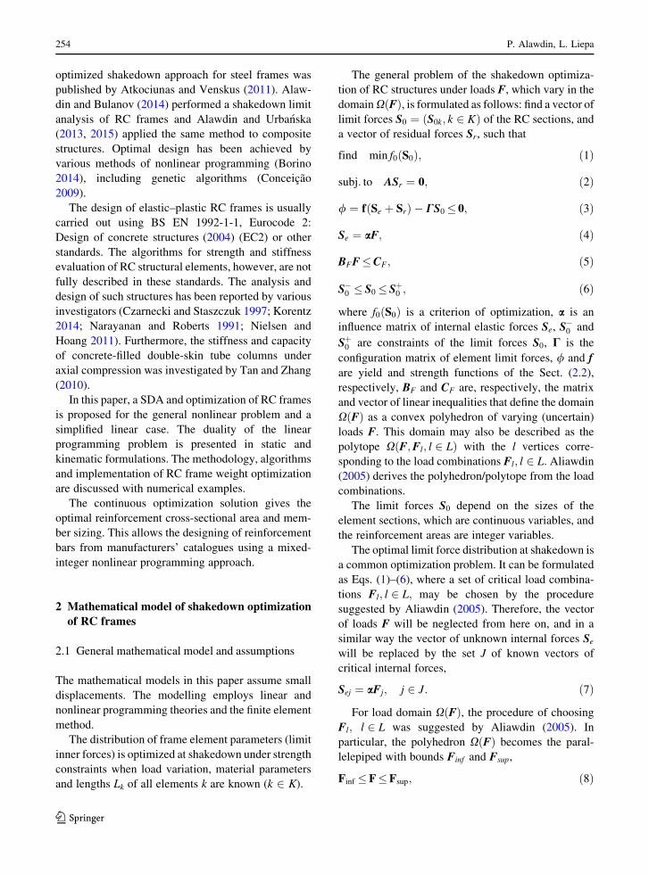
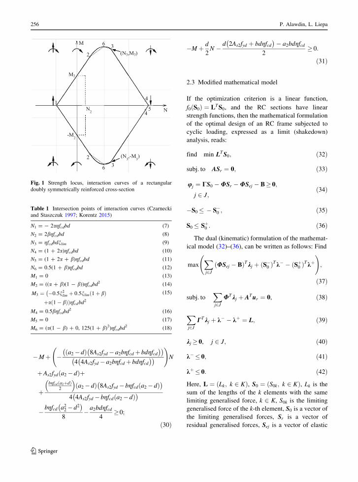
2.2 Yielding conditions of RC cross-sections
S0k ¼ ðM0k;N0kÞ; k 2 K; are functions of cross-sec-
tional geometry and material properties. These func-
tions may be linear or nonlinear; they are presented in
Fig. 1 for rectangular doubly RC cross-sections. The
functions were derived by Czarnecki and Staszczuk
(1997) and later adapted to Eurocode 2 by Korentz
(2014), thus they are not investigated further here.
In Fig. 1, there are six unique points where interac-
tion curves intersect each other. These intersection
points represent different states of RC cross-sec-
tion. Point 1: the tension failure state of the cross-
section; Point 2: the point where the parabolic curve
(2–6) intersects the line (1–2); Point 3: the point where
the parabolic curve (6–3) intersects the line (3–4); Point
4: compressive failure followed by the rapid increase of
axial force (M = 0); Point 5: pure compression failure
(M = 0); Point 6: balanced failure, assuming that the
tensile steel reaches its yield strength and the com-
pressed concrete reaches its compressive strain limit
(ecu = 0.0035) simultaneously. The dashed lines
between line segments 2–6 and 6–3 show the linearized
forms of the nonlinear strength locus curves. In the case
of asymmetric reinforcement, this interaction locus
would have different upper and lower parts.
The points of intersection of each interaction curve
are provided in Table 1, sourced from Czarnecki and
Staszczuk (1997) and Korentz (2015).
The coefficients a, b, k1 can be determined from the
following formulae:
a ¼ fydAs1=k1; ð19Þ
b ¼ a1=k1; ð20Þ
k1 ¼ gfcdbd: ð21Þ
Here, g is a coefficient defining effective strength and ifg = 1.0 then fck � 50 MPa (Eurocode 2), where fckis
the cylindrical characteristic compressive concrete
strength after 28 days of curing; fcd is the computa-
tional concrete strength, for C30/37 it is fcd ¼ 20 MPa;
b is the width of the cross-section, see Fig. 2; d is the
distance from the top of the section to the tensioning
reinforcement, see Fig. 2; nlim is the limiting value of
the relative height of the compression zone, for the
C30/37 and reinforcement class B400 it is nlim =
0.534.
From these intersection points (Table 1) one can
derive linear functions that provide a linear approx-
imation of the strength locus of a rectangular doubly
reinforced cross-section (see Fig. 2). These functions
in linear form can be written as follows:
M þ a1 � d
2
� �N þ As1fyd a1 � dð Þ� 0; ð22Þ
M þ a1 � d þ dnlim2
� �N þ As1fyd a1 � dð Þ
� a1gfcdbdnlim � 0; ð23Þ
M þ 2dnlim � d � a1
4
� �N þ As1fyd a1 � dð Þ
� bdgfcdnlim d � a1ð Þ4
� 0; ð24Þ
M þ �a1 � dð Þ 8As1fyd � a1bgfcd þ bdgfcd
� �� �4 4As1fyd � a1bgfcd þ bdgfcd� �� �
!N
þ As1fyd a1 � dð Þþ
þbgfcd a1þdð Þ
2
� �a1 � dð Þ 8As1fyd � bgfcd a1 � dð Þ
� �4 4As1fyd � bgfcd a1 � dð Þ� �
�bgfcd a21 � d2
� �8
� a1bdgfcd4
� 0; ð25Þ
M þ d
2N �
d 2As1fyd þ bdgfcd� �
� a1bdgfcd2
� 0;
ð26Þ
�M þ a2 � d
2
� �N þ As2fyd a2 � dð Þ� 0; ð27Þ
�M þ a2 � d þ dnlim2
� �N þ As2fyd a2 � dð Þ
� a2gfcdbdnlim � 0; ð28Þ
�M þ 2dnlim � d � a2
4
� �N þ As2fyd a2 � dð Þ
� bdgfcdnlim d � a2ð Þ4
� 0; ð29Þ
Optimal shakedown analysis of plane reinforced concrete frames according to Eurocodes 255
123
Page 4
�Mþ �a2� dð Þ 8As2fyd � a2bgfcd þ bdgfcd
� �� �4 4As2fyd � a2bgfcd þ bdgfcd� �� �
!N
þAs2fyd a2� dð Þþ
þbgfcd a2þdð Þ
2
� �a2� dð Þ 8As2fyd � bgfcd a2� dð Þ
� �4 4As2fyd � bgfcd a2� dð Þ� �
�bgfcd a22� d2
� �8
� a2bdgfcd4
�0;
ð30Þ
�M þ d
2N �
d 2As2fyd þ bdgfcd� �
� a2bdgfcd2
� 0:
ð31Þ
2.3 Modified mathematical model
If the optimization criterion is a linear function,
f0ðS0Þ ¼ LTS0, and the RC sections have linear
strength functions, then the mathematical formulation
of the optimal design of an RC frame subjected to
cyclic loading, expressed as a limit (shakedown)
analysis, reads:
find min LTS0; ð32Þ
subj: to ASr ¼ 0; ð33Þ
uj ¼ CS0 �USr �USej � B� 0;
j 2 J;ð34Þ
�S0 � � S�0 ; ð35Þ
S0 � Sþ0 : ð36Þ
The dual (kinematic) formulation of the mathemat-
ical model (32)–(36), can be written as follows: Find
maxXj2J
ðUSej � BÞTkj þ ðS�0 ÞTk� � ðSþ0 Þ
Tkþ !
;
ð37Þ
subj: toXj2J
UTkj þ ATur ¼ 0, ð38Þ
Xj2J
CTkj þ k� � kþ ¼ L; ð39Þ
kj � 0, j 2 J; ð40Þ
k� � 0; ð41Þ
kþ � 0: ð42Þ
Here, L ¼ ðLk; k 2 KÞ, S0 ¼ ðS0k; k 2 KÞ, Lk is the
sum of the lengths of the k elements with the same
limiting generalised force, k 2 K, S0k is the limiting
generalised force of the k-th element, S0 is a vector of
the limiting generalised forces, Sr is a vector of
residual generalised forces, Sej is a vector of elastic
N
M
1
2
6 3
4
54
36
2
(N3,M3)
(N3,-M
3)
M2
-M2
N2
Fig. 1 Strength locus, interaction curves of a rectangular
doubly symmetrically reinforced cross-section
Table 1 Intersection points of interaction curves (Czarnecki
and Staszczuk 1997; Korentz 2015)
N1 = - 2agfcdbd (7)
N2 = 2bgfcdbd (8)
N3 = gfcdbdnlim (9)
N4 = (1 ? 2a)gfcdbd (10)
N5 = (1 ? 2a ? b)gfcdbd (11)
N6 = 0.5(1 ? b)gfcdbd (12)
M1 = 0 (13)
M2 = ((a ? b)(1 - b))gfcdbd2 (14)
M3 ¼ �0:5n2lim þ 0:5nlim 1þ bð Þ�þa 1� bð ÞÞgfcdbd2
(15)
M4 = 0.5bgfcdbd2 (16)
M5 = 0 (17)
M6 = (a(1 - b) ? 0, 125(1 ? b)2)gfcdbd2 (18)
256 P. Alawdin, L. Liepa
123
Page 5
generalised forces at load locus apex j 2 J, kj is a
vector of plastic multipliers, j 2 J, k� and kþ are
vectors of multipliers according to the constraints
(35)–(36), ur is a vector of residual displacements,
U ¼ diagUi is a quasi-diagonal matrix of the linear
yielding conditions (22)–(31), where Ui is the matrix
of coefficients of the linear yielding conditions of the i-
th section, B ¼ B1 B2 � � � Bi½ �T is a vector of thefree units of linear yielding conditions (22)–(31). See
Table 2 for the matrix Ui and vector B of free units
and linear yielding conditions for the i-th section.
The problem of structural optimization at shake-
down is stated as follows: given the load variation
bounds Fsup and Finf , find the vector of limit forces S0;
satisfying the optimisation criterion and the con-
straints of shakedown and construction requirements
(Atkociunas and Venskus 2011).
The limit forces S0k, k 2 K of elements and the
vectors of plastic multipliers kj � 0; j 2 J are
unknowns in problem (32)–(36). The limit forces S0kare components of vector S0. Conditions (35), (36),
which restricts the maximum (�S�0 ) and minimum
(Sþ0 ) values of limit forces S0, performs the function of
constructive constraint (Atkociunas 2011).
The general solution of the problem (32)–(36) can be
derived in the following order. The geometrical param-
eters of the rectangular cross-section—height h, width b,
and reinforcement clearances a1 and a2, are known and
constant. The initial limit forces S0ok, i.e., moments M0ok
and axial forces N0ok (k 2 K), are prescribed. The
design of the steel reinforcement A0s1 and A0
s2 is
performed according to the scheme in Fig. 3. The
initial influence matrices a0; b0; G0; H0 are calcu-
lated, then the problem (32)–(36) is solved. Later,
when a new distribution of limit moments Mnewok and
axial forces Nnewok (k 2 K) is determined, the new
reinforcement design is implemented and new Anews1
and Anews2 are obtained. Updated influence matrices
anew; bnew; Gnew; Hnew are computed for the next
iteration. From these matrices, the elastic response is
determined, which consists of displacements uej and
internal forces Sej.
For the linear yield conditions (34), the residual
displacements ur ¼ Hk and residual internal forces
Sr ¼ Gk can be expressed by influence matrices of
residual displacements (43) and forces (44):
H ¼ AD�1AT� ��1
AD�1� �
U; ð43Þ
(a)
(b)
Fig. 2 Reinforcement
design of a rectangular
eccentrically compressed
cross-section (doubly
symmetrically reinforced);
a large eccentricity, b small
eccentricity
Optimal shakedown analysis of plane reinforced concrete frames according to Eurocodes 257
123
Page 6
Table
2Quasi-diagonal
matrixoflinearyieldingconditions
Ui
ðÞandthevectoroffree
units
BðÞforthei-th
cross-section
Ui¼
1ai;1�di
2
��
1ai;1�diþdin
lim;i
2
��
12din
lim;i�di�ai;1
4
��
1�
ai;1�di
�� 8
Ai;s1f yd�ai;1bigf cdþbid
igf cd
��
��
44Ai;s1f yd�ai;1bigf cdþbid
igf cd
��
��
!
1di 2
�1
ai;2�di
2
��
�1
ai;2�diþdin
lim;i
2
��
�1
2din
lim;i�di�ai;2
4
��
�1
�ai;2�di
�� 8
Ai;s2f yd�ai;2bigf cdþbid
igf cd
��
��
44Ai;s2f yd�ai;2bigf cdþbid
igf cd
��
��
!
�1
di 2
2 6 6 6 6 6 6 6 6 6 6 6 6 6 6 6 6 6 6 6 6 6 6 6 6 6 6 6 6 6 6 6 6 6 6 6 6 6 4
3 7 7 7 7 7 7 7 7 7 7 7 7 7 7 7 7 7 7 7 7 7 7 7 7 7 7 7 7 7 7 7 7 7 7 7 7 7 5;
Bi¼
Ai;s1f ydai;1�di
��
Ai;s1f ydai;1�di
�� �
ai;1gf
cdbid
inlim
Ai;s1f ydai;1�di
�� �
bid
igf cdn lim
di�ai;1
��
4
Ai;s1f ydai;1�di
�� þ
bigf cdai;1þdi
��
2
�� a
i;1�di
�� 8
Ai;s1f yd�bigf cdai;1�di
��
��
44Ai;s1f yd�bi;gf
cdai;1�di
��
��
�
�bigf cd
a2 i;1�d2 i
��
8�ai;1bid
igf cd
4
�di2Ai;s1f ydþbid
igf cd
�� �
ai;1bid
igf cd
2Ai;s2f ydai;2�di
��
Ai;s2f ydai;2�di
�� �
ai;2gf
cdbid
inlim
Ai;s2f ydai;2�di
�� �
bid
igf cdn lim
di�ai;2
��
4
Ai;s2f ydai;2�di
�� þ
bigf cdai;2þdi
��
2
�� a
i;2�di
�� 8
Ai;s2f yd�bigf cdai;2�di
��
��
44Ai;s2f yd�bi;gf
cdai;2�di
��
��
�
�bigf cd
a2 i;2�d2 i
��
8�ai;2bid
igf cd
4
�di2Ai;s2f ydþbid
igf cd
�� �
ai;2bid
igf cd
2
2 6 6 6 6 6 6 6 6 6 6 6 6 6 6 6 6 6 6 6 6 6 6 6 6 6 6 6 6 6 6 6 6 6 6 6 6 6 6 6 6 6 6 6 4
3 7 7 7 7 7 7 7 7 7 7 7 7 7 7 7 7 7 7 7 7 7 7 7 7 7 7 7 7 7 7 7 7 7 7 7 7 7 7 7 7 7 7 7 5:
258 P. Alawdin, L. Liepa
123
Page 7
G ¼ D�1ATH � D�1U: ð44Þ
Problem (32)–(36) is solved, therefore, in an iterative
approach. The process is deemed to be finished when
selected cross-sectional characteristics are within a
prescribed tolerance (eps, see Fig. 3) of those from the
previous iteration, giving the optimal solution S�ok, k�j ,
k 2 K, j 2 J of the problem (32)–(36). Having
obtained this solution, it is possible to indirectly
calculate the volume of the frames (32); as described
by Atkociunas and Karkauskas (2010) and Atkociunas
(2011).
Remark 2.1 A solution of problem (32)–(36) may
have Jl active inequalities (34) for a single element
cross-section subject to Jl loads. This regime of plastic
yielding is termed sign-changing. In such a casewemay
calculate this element cross-section as being elastic.
Remark 2.2 Inequalities (34) generally depend on
the domainXðFÞ of loading (Aliawdin 2005; Aliawdinand Kasabutski 2009); the checking of this effect
may be a problem addressed in Eurocode’s future
variants.
Remark 2.3 In the formulation of problem (32)–(36),
one may include not only the unknown load, but also
any other actions, material properties or geometrical
imperfections of the structure (e.g., see Elishakoff
et al. 2013).
The influence matrices a, of the elastic internal
forces, and b, of the elastic displacements, are
generally calculated by
a ¼ D�1AT AD�1AT� ��1
; ð45Þ
b ¼ AD�1AT� ��1
; ð46Þ
where A Lkf g is matrix of coefficients of equilibrium
equations and D Itr;Atr;Ecomp
� is a flexibility matrix
of the transformed cross-section; see Atkociunas and
Karkauskas (2010), Atkociunas (2011) and Liepa et al.
(2014). The transformation of the cross-section needs
to be performed because RC cross-sections are
composed of two materials. Their geometrical char-
acteristics, such as moment of inertia Itr and area of
cross-section Atr, can be determined using methods
described by Beardmore (2011). The elastic modulus
of composite material Ecomp is determined according
to the Derivation of the Rule of Mixtures and Inverse
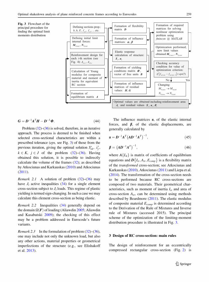
rule of Mixtures (accessed 2015). The principal
scheme of the optimization of the limiting-moment
distribution procedure is illustrated in Fig. 3.
3 Design of RC cross-section: main rules
The design of reinforcement for an eccentrically
compressed rectangular cross-section (Fig. 2) is
Fig. 3 Flowchart of the
principal procedure for
finding the optimal limit
moments distribution
Optimal shakedown analysis of plane reinforced concrete frames according to Eurocodes 259
123
Page 8
carried out according to the Eurocode 2 recommen-
dations. The flowchart of the implemented design
procedure is shown in Fig. 4.
Here, M0 and N0 are, respectively, the limiting
moment and limiting axial force of the RC cross-
section; e is the ratio of internal forces (eccentricity of
axial force from the centre of the cross-section); e1 and
e2 are eccentricities (refer to Fig. 2); b is the width of
the RC cross-section; h is the height of the RC cross-
section; d is the distance of the designed reinforcement
bar’s centre to the opposite outside layer of the RC
element; a1 and a2 are the clearance distances of
reinforcement; fyd is the designed yield strength of
steel reinforcement; js i the reduction coefficient of
steel reinforcement yield strength; xeff is an effective
height of the compressive concrete zone; xeff,lim is the
Fig. 4 Flowchart of the reinforcement design procedure
260 P. Alawdin, L. Liepa
123
Page 9
limit of the effective height of the compressive
concrete zone; x’ is the equivalent height of the
compressive concrete zone; q is the ratio of required
reinforcement; qmin is the minimal ratio of required
reinforcement; qmax is the maximal allowed ratio of
required reinforcement.
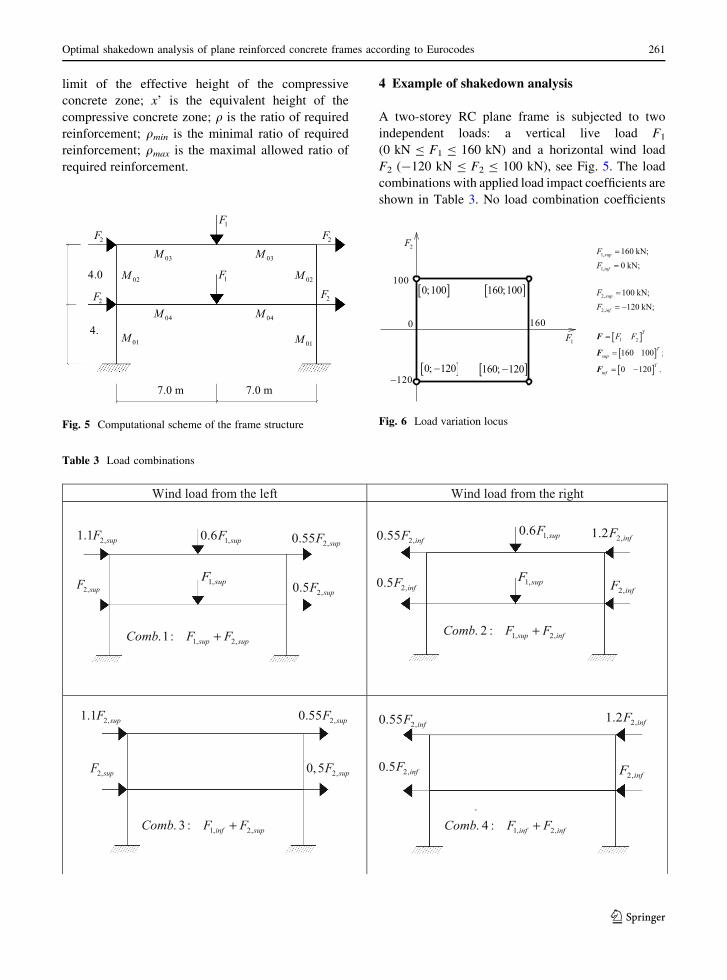
4 Example of shakedown analysis
A two-storey RC plane frame is subjected to two
independent loads: a vertical live load F1
(0 kN B F1 B 160 kN) and a horizontal wind load
F2 (-120 kN B F2 B 100 kN), see Fig. 5. The load
combinations with applied load impact coefficients are
shown in Table 3. No load combination coefficients
2F
2F
2F
2F1F
1F
7.0 m 7.0 m
4.
4.0
01M
02M 02M
01M
03M 03M
04M 04M
Fig. 5 Computational scheme of the frame structure
Table 3 Load combinations
Wind load from the left Wind load from the right
2,0.55 infF
2,0.5 infF
2,1.2 infF
2,infF
1, 2,. 4 : inf infComb F F+
2,0.55 infF
2,0.5 infF2,infF
2,1.2 infF1,0.6 supF
1,supF
1, 2,. 2 : sup infComb F F+
2,1.1 supF
2,supF
2,0.55 supF
2,0, 5 supF
1, 2,. 3 : inf supComb F F+
2,1.1 supF
2,supF2,0.5 supF
2,0.55 supF1,0.6 supF
1,supF
1, 2,.1: sup supComb F F+
Fig. 6 Load variation locus
Optimal shakedown analysis of plane reinforced concrete frames according to Eurocodes 261
123
Page 10
were applied. The task is to find an optimal solution to
the problem (32)–(36) for determining the distribution
of limit moments on the frame at shakedown.
The load variation ranges can be described as a
locus, as in Fig. 6.
The impact coefficients of the loads were assigned
arbitrarily, but can be determined according to the
requirements of the standards.
The discrete model of the frame structure is shown
in Fig. 7. The frame is discretized into eight finite
beam elements (number in square), each with two
sections. The frame is k = 6 times statically indeter-
minate, it has n = 24 internal forces, and m = 18
possible directions of nodal displacements (i.e.,
degrees of freedom DOF = 18). Each finite element
has two bending moments (one per section) and an
axial force (one per element).
F1;sup ¼ 160 kN;
F1;inf ¼ 0 kN;
F2;sup ¼ 100 kN;
F2;inf ¼ �120 kN;
F ¼ F1 F2½ �T
Fsup ¼ 160 100½ �T ;Finf ¼ 0 � 120½ �T :
5 Solution
The initial geometrical parameters of the sections and
reinforcement cross-sectional areas, designed accord-
ing to the initial limiting bending moments and axial
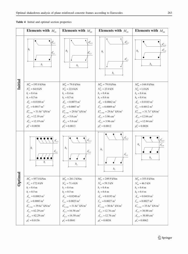
forces, are presented in Table 4.
The optimal solution of problem (32)–(36) for the
frame in question was obtained after eight iterations.
The value of the optimal criterion function after eight
iterations was f� ¼ 1:8633; see Fig. 8. The final value
was 1.17 % larger than the initial value of the optimal
criterion function after the first iteration, f0 = 1.8415.
This small difference, however, produces a significant
change ([65 %) in the reinforcement areas for all
cross-sections. Table 4 presents the optimal reinforce-
ment cross-sectional areas and geometrical parameters
of frame cross-sections.
From Table 4, the initial reinforcements of the four
sections are:
1
2
3 13
4 5 6 7
8 9
10
11
12
14 15 16
1
2
3 4
5
6
7 8
1
2 3 4
56
7
8
9
10
11
12
13 14
15
16
17
18
x
y
Fig. 7 Discrete model of the frame and possible directions of nodal displacements
1 2 3 4 5 6 7 8 91.84
1.845
1.85
1.855
1.86
1.865 x 10⁴
No. of iterations
Val
ue o
f opt
imal
crit
erio
n fu
nctio
n
Fig. 8 Optimal solution convergence during the iterative
procedure
262 P. Alawdin, L. Liepa
123
Page 11
Table 4 Initial and optimal section properties
4b
4h
02,4sA
01,4sA
Elements with 01M Elements with 02M Elements with 03M Elements with 04M
Initi
al
001001
1
10 21,
0 41,
0 6 21,
0 21,1
0 22,1
01
195.0 kNm
64.0 kN0.4 m0.5 m
0.0188 m
0.0017 m
31.0 kN/m
12.19 cm
12.19 cm
0.0030
tr
tr
comp
s
s
MNbhA
I
E e
A
A
ρ
=
===
=
=
=
=
=
=
002002
2
20 22,
0 42,
0 6 22,
0 21,2
0 22,2
02
79.0 kNm
22.0 kN0.4 m0.5 m
0.0075 m
0.0007 m
29.8 kN/m
5.0 cm
5.0 cm
0.0013
tr
tr
comp
s
s
MNbhA
I
E e
A
A
ρ
=
===
=
=
=
=
=
=
003003
3
30 23,
0 43,
0 6 23,
0 21,3
0 22,3
03
79.0 kNm
23.0 kN0.4 m0.6 m
0.0062 m
0.0009 m
29.6 kN/m
3.96 cm
3.96 cm
0.0012
tr
tr
comp
s
s
MNbhA
I
E e
A
A
ρ
=
===
=
=
=
=
=
=
004004
4
40 24,
0 44,
0 6 24,
0 21,4
0 22,4
04
144.0 kNm
1.0 kN0.4 m0.4 m
0.0165 m
0.0012 m
31.7 kN/m
12.84 cm
12.84 cm
0.0026
tr
tr
comp
s
s
MNbhA
I
E e
A
A
ρ
=
===
=
=
=
=
=
=
Opt
imal
*01*01
1
1* 21,
* 41,
* 6 21,
* 21,1
* 22,1
*1
957.0 kNm
172.8 kN0.4 m0.5 m
0.0883 m
0.0083 m
39.6 kN/m
62.29 cm
62.29 cm
0.0156
tr
tr
comp
s
s
MNbhA
I
E e
A
A
ρ
=
===
=
=
=
=
=
=
*02*02
2
2* 22,
* 42,
* 6 22,
* 21,2
* 22,2
*2
261.3 kNm
71.4 kN0.4 m0.5 m
0.0248 m
0.0023 m
31.8 kN/m
16.58 cm
16.58 cm
0.0041
tr
tr
comp
s
s
MNbhA
I
E e
A
A
ρ
=
===
=
=
=
=
=
=
*03*03
3
3* 23,
* 43,
* 6 23,
* 21,3
* 22,3
*3
249.9 kNm
59.3 kN0.4 m0.6 m
0.0193 m
0.0027 m
30.8 kN/m
12.76 cm
12.76 cm
0.0038
tr
tr
comp
s
s
MNbhA
I
E e
A
A
ρ
=
===
=
=
=
=
=
=
*04*04
4
4* 24,
* 44,
* 6 24,
* 21,4
* 22,4
*4
355.0 kNm
46.5 kN0.4 m0.4 m
0.0418 m
0.0027 m
35.6 kN/m
30.88 cm
30.88 cm
0.0062
tr
tr
comp
s
s
MNbhA
I
E e
A
A
ρ
=
===
=
=
=
=
=
=
4h
4b
*2,4sA
*1,4sA
3h
3b
*2,3sA
*1,3sA
2h
2b
*2,2sA
*1,2sA
1h
1b
*2,1sA
*1,1sA
3b
3h
02,3sA
01,3sA
2b
2h
02,2sA
01,2sA
1b
1h
02,1sA
01,1sA
Optimal shakedown analysis of plane reinforced concrete frames according to Eurocodes 263
123
Page 12
M01: A0s1;1 ¼ A0
s2;1 ¼ 12:19 cm2; which can be
designed as 2� 2;28 (2 9 12.32 cm2)1;
M02: A0s1;2 ¼ A0
s2;2 ¼ 5:0 cm2; which can be
designed as 2� 2;18 (2 9 5.08 cm2) (see footnote
1);
M03: A0s1;3 ¼ A0
s2;3 ¼ 3:96 cm2; which can be
designed as 2� 2;16 (2 9 4.02 cm2) (see footnote
1);
M04: A0s1;4 ¼ A0
s2;4 ¼ 12:84 cm2; which can be
designed as 2� 2;32 (2 9 16.08 cm2) (see foot-
note 1).
Likewise, the optimal reinforcements of these
sections are:
M01: A�s1;1 ¼ A�
s2;1 ¼ 62:29 cm2; which can be
designed as 2� 5;40 (2 9 62.85 cm2) (see foot-
note 1);
M02: A�s1;2 ¼ A�
s2;2 ¼ 16:58 cm2; which can be
designed as 2� 3;28 (2 9 18.48 cm2) (see foot-
note 1);
M03: A�s1;3 ¼ A�
s2;3 ¼ 12:76 cm2; which can be
designed as 2� 3;25 (2 9 14.73 cm2) (see foot-
note 1);
M04: A�s1;4 ¼ A�
s2;4 ¼ 30:88 cm2; which can be
designed as 2� 3;36 (2 9 30.54 cm2) (see foot-
note 1).
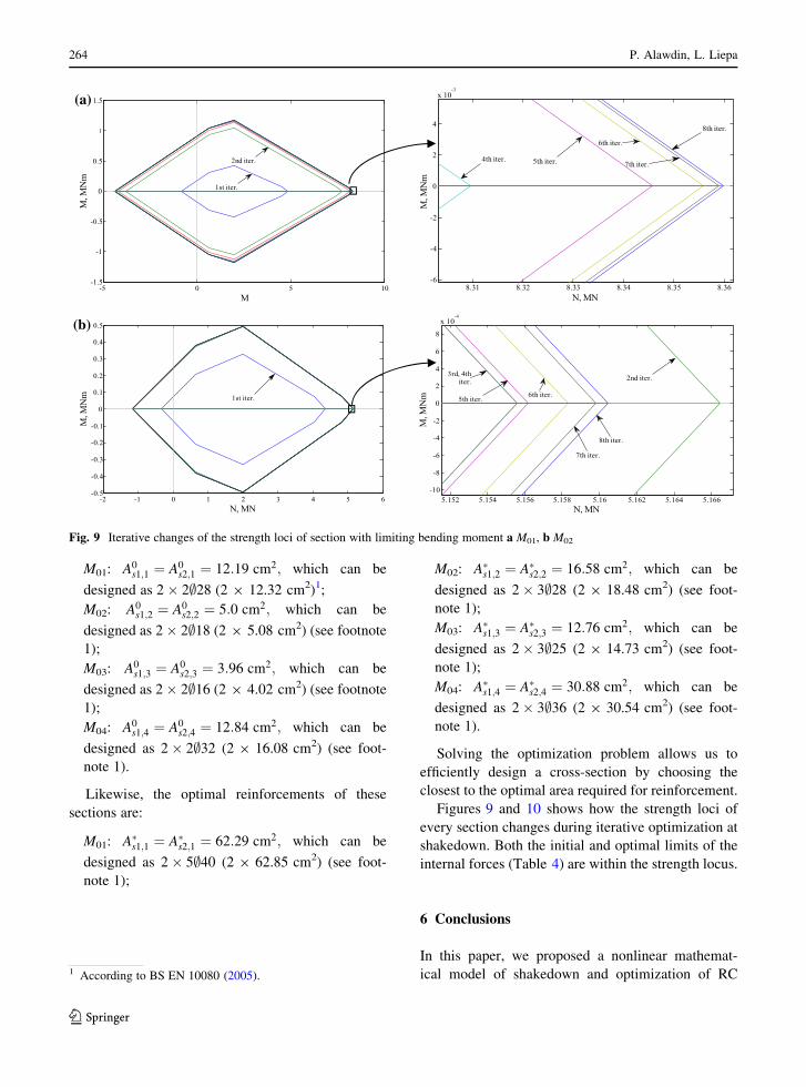
Solving the optimization problem allows us to
efficiently design a cross-section by choosing the
closest to the optimal area required for reinforcement.
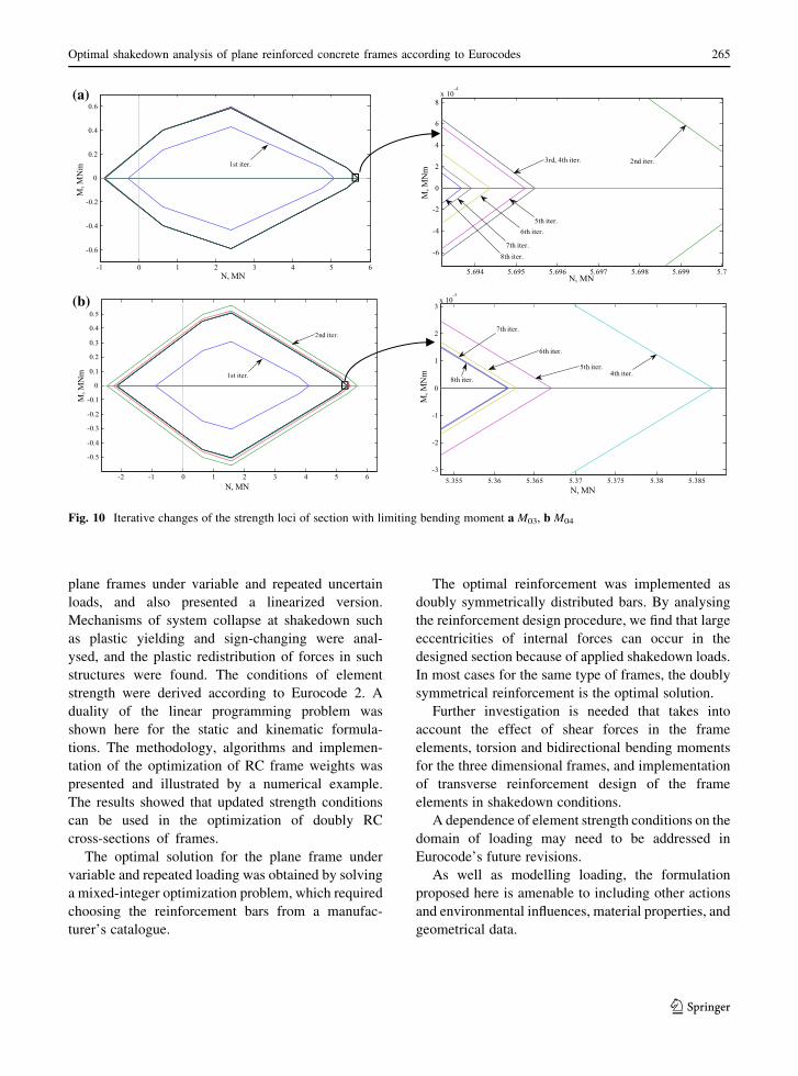
Figures 9 and 10 shows how the strength loci of
every section changes during iterative optimization at
shakedown. Both the initial and optimal limits of the
internal forces (Table 4) are within the strength locus.
6 Conclusions
In this paper, we proposed a nonlinear mathemat-
ical model of shakedown and optimization of RC
-5 0 5 10-1.5
-1
-0.5
0
0.5
1
1.5
M
M, M
Nm
1st iter.
2nd iter.
8.31 8.32 8.33 8.34 8.35 8.36-6
-4
-2
0
2
4
x 10-3
N, MN
M, M
Nm
4th iter. 5th iter.
6th iter.
8th iter.
7th iter.
-2 -1 0 1 2 3 4 5 6-0.5
-0.4
-0.3
-0.2
-0.1
0
0.1
0.2
0.3
0.4
0.5
N, MN
M, M
Nm 1st iter.
5.152 5.154 5.156 5.158 5.16 5.162 5.164 5.166-10
-8
-6
-4
-2
0
2
4
6
8
x 10-4
N, MN
M, M
Nm
2nd iter.3rd, 4th iter.
5th iter. 6th iter.
7th iter.
8th iter.
(a)
(b)
Fig. 9 Iterative changes of the strength loci of section with limiting bending moment a M01, b M02
1 According to BS EN 10080 (2005).
264 P. Alawdin, L. Liepa
123
Page 13
plane frames under variable and repeated uncertain
loads, and also presented a linearized version.
Mechanisms of system collapse at shakedown such
as plastic yielding and sign-changing were anal-
ysed, and the plastic redistribution of forces in such
structures were found. The conditions of element
strength were derived according to Eurocode 2. A
duality of the linear programming problem was
shown here for the static and kinematic formula-
tions. The methodology, algorithms and implemen-
tation of the optimization of RC frame weights was
presented and illustrated by a numerical example.
The results showed that updated strength conditions
can be used in the optimization of doubly RC
cross-sections of frames.
The optimal solution for the plane frame under
variable and repeated loading was obtained by solving
a mixed-integer optimization problem, which required
choosing the reinforcement bars from a manufac-
turer’s catalogue.
The optimal reinforcement was implemented as
doubly symmetrically distributed bars. By analysing
the reinforcement design procedure, we find that large
eccentricities of internal forces can occur in the
designed section because of applied shakedown loads.
In most cases for the same type of frames, the doubly
symmetrical reinforcement is the optimal solution.
Further investigation is needed that takes into
account the effect of shear forces in the frame
elements, torsion and bidirectional bending moments
for the three dimensional frames, and implementation
of transverse reinforcement design of the frame
elements in shakedown conditions.
A dependence of element strength conditions on the
domain of loading may need to be addressed in
Eurocode’s future revisions.
As well as modelling loading, the formulation
proposed here is amenable to including other actions
and environmental influences, material properties, and
geometrical data.
(a)
(b)
-1 0 1 2 3 4 5 6
-0.6
-0.4
-0.2
0
0.2
0.4
0.6
N, MN
M, M
Nm 1st iter.
5.694 5.695 5.696 5.697 5.698 5.699 5.7
-6
-4
-2
0
2
4
6
8x 10
-4
N, MN
M, M
Nm
2nd iter.3rd, 4th iter.
5th iter.6th iter.
7th iter.8th iter.
-2 -1 0 1 2 3 4 5 6
-0.5
-0.4
-0.3
-0.2
-0.1
0
0.1
0.2
0.3
0.4
0.5
N, MN
M, M
Nm 1st iter.
2nd iter.
5.355 5.36 5.365 5.37 5.375 5.38 5.385-3
-2
-1
0
1
2
3x 10
-3
N, MN
M, M
Nm 8th iter.
7th iter.
6th iter.
5th iter.4th iter.
Fig. 10 Iterative changes of the strength loci of section with limiting bending moment a M03, b M04
Optimal shakedown analysis of plane reinforced concrete frames according to Eurocodes 265
123
Page 14
Open Access This article is distributed under the terms of the
Creative Commons Attribution 4.0 International License (http://
creativecommons.org/licenses/by/4.0/), which permits unrest-
ricted use, distribution, and reproduction in any medium, pro-
vided you give appropriate credit to the original author(s) and
the source, provide a link to the Creative Commons license, and
indicate if changes were made.
References
Aliawdin, P.W.: Limit Analysis of Structures Under Variable
Loads. Technoprint, Minsk (2005) (in Russian)Aliawdin, P., Kasabutski, S.: Limit and shakedown analysis of
RC rod cross-sections. J. Civ. Eng. Manag. 15(1), 59–66(2009). doi:10.3846/1392-3730.2009.15.59-66
Alawdin, P., Urbanska, K.: Limit analysis of geometrically
hardening rod systems using bilevel programming. In:
Proceedings of 11th International Scientific Conference on
Modern Building Materials, Structures and Techniques,
Vilnius, Lithuania, pp. 89–98 (2013). doi:10.1016/j.
proeng.2013.04.014
Alawdin, P., Bulanov, G.: Shakedown of composite frames
taking into account plastic and brittle fracture of elements.
Civ. Environ. Eng. Rep. 15(4), 5–21 (2014). doi:10.1515/
ceer-2014-0031
Alawdin, P., Urbanska, K.: Limit analysis of geometrically
hardening composite steel-concrete systems. Civ. Environ.
Eng. Rep. 16(1), 5–23 (2015). doi:10.1515/ceer-2015-0001Atkociunas, J., Karkauskas, R.: Optmization of Elastic Plastic
Beam Structures. Technika, Vilnius (2010) (in Lithuanian)Atkociunas, J., Venskus, A.: Optimal shakedown design of
frames under stability conditions according to standards.
Comput. Struct. 89(3–4), 435–443 (2011). doi:10.1016/j.
compstruc.2010.11.014
Atkociunas, J.: Optimal Shakedown Design of Elastic–Plastic
Structures. Technika, Vilnius (2011)
Beardmore, R.: Reinforced concrete background theory, Roy-
mech. http://www.roymech.co.uk/Related/Construction/
Concrete_beams_theory.html (2011). Accessed 10 April
2015
Borino, G.: Shakedown under thermomechanical loads. In:
Hetnarski, R.B. (ed.) Encyclopedia of Thermal Stresses.
Springer, Netherlands (2014)
BS EN 1992–1–1: Eurocode 2, Design of concrete structures
Part 1–1: General Rules and Rules for Buildings. CEN,
Brussels (2004)
BS EN 10080: Steel for the Reinforcement of Concrete.
Weldable Reinforcing Steel. General, CEN, Brussels
(2005)
Conceicao, A.C.: Self-adaptation procedures in genetic algo-
rithms applied to the optimal design of composite struc-
tures. Int. J. Mech. Mater. Des. 5, 289–302 (2009). doi:10.1007/s10999-009-9102-x
Cyras, A.: Linear Programming in the Design of Elastic-Plastic
Systems. Sroizdat, Leningrad (1969) (in Russian)Cyras, A.: Mathematical Models for the Analysis and Opti-
mization of Elastoplastic Structures. Ellis Horwood Lim-
ited, Chichester (1983)
Czarnecki, W., Staszczuk, P.: Design of Reinforced Concrete
Columns. Technical University of Zielona Gora, Poland
(1997) (in Polish)Derivation of the Rule of Mixtures and Inverse rule of Mixtures.
DoITPoMS, University of Cambridge. http://www.
doitpoms.ac.uk/tlplib/bones/derivation_mixture_rules.php.
Accessed 11 April 2015
Elishakoff, I., Wang, X., Li, Y., Hu, J., Qiu, Z.: Regulating the
dynamic behavior of a column with uncertain initial
imperfections by support-placing. Int. J. Solids Struct.
50(2), 396–402 (2013)
Guerra, A., Kiousis, P.D.: Design optimization of reinforced
concrete structures. Comput. Concr. 3(5), 313–334 (2006).doi:10.12989/cac.2006.3.5.313
Guerra, A., Newman, A.M., Leyffer, S.: Concrete structure
design using mixed-integer nonlinear programming with
complementarity constraints. SIAM J. Optim. 21(3),833–863 (2011). doi:10.1137/090778286
Korentz, J.: Methods of analysis of a reinforced concrete section
under bending with axial force in the post-critical range.
Build. Arch. 13(3), 119–126 (2014) (in Polish)Korentz, J.: Method of Analysing Reinforced Beams and Col-
umns in the Post Yield Range. Monograph Polish Academy
of Sciences, Warsaw (2015) (in Polish)Konig, J.A.: Shakedown of Elastic–plastic Structures. PWN,
Warszawa, Elsevier, Amsterdam (1987)
Liepa, L., Gervyte, A., Jarmolajeva, E., Atkociunas, J.: Residual
displacements progressive analysis of the multisupported
beam. Sci. Future Lith. 6(5), 461–467 (2014). doi:10.3846/mla.2014.686 (in Lithuanian)
Narayanan, R., Roberts, T.M.: Structures Subjected to Repeated
Loading: Stability and Strength. Elsevier, London and New
York (1991)
Nielsen, M.P., Hoang, L.C.: Limit Analysis and Concrete
Plasticity, (3rd Edition). CRC Press, Taylor & Francis
Group, Boca Raton (2011)
Nguyen, Q.S.: Min-max duality and shakedown theorems in
plasticity. In: Alart, P., Maisonneuve, O., Rockafellar, R.T.
(eds.) Nonsmooth Mechanics and Analysis: Theoretical
and Numerical Advances. Springer, Berlin (2006)
Tan, K.H., Zhang, Y.F.: Compressive stiffness and strength of
concrete filled double skin (CHS inner & CHS outer) tubes.
Int. J. Mech. Mater. Des. 6, 283–291 (2010). doi:10.1007/
s10999-010-9138-y
Weichert, D., Maier, G.: Inelastic Behavior of Structures under
Variable Repeated Loads. Springer, Wien (2002)
Weichert, D., Ponter, A.: Limit States of Materials and Struc-
tures. Springer, Wien (2009)
266 P. Alawdin, L. Liepa
123