44
OPTIMAL SPEED AND TORQUE ESTIMATION FOR IMPROVING THE DTC DYNAMIC PERFORMANCE OF INDUCTION MACHINES IBRAHIM MOHD ALI ALSOFYANI UNIVERSITI TEKNOLOGI MALAYSIA
| Date post: | 06-Aug-2019 |
| Category: |
Documents |
| Upload: | nguyenliem |
| View: | 212 times |
| Download: | 0 times |

OPTIMAL SPEED AND TORQUE ESTIMATION FOR IMPROVING THE DTC
DYNAMIC PERFORMANCE OF INDUCTION MACHINES
IBRAHIM MOHD ALI ALSOFYANI
UNIVERSITI TEKNOLOGI MALAYSIA
i
OPTIMAL SPEED AND TORQUE ESTIMATIONS FOR IMPROVING THE DTC
DYNAMIC PERFORMANCE OF INDUCTION MACHINES
IBRAHIM MOHD ALI ALSOFYANI
A thesis submitted in fulfilment of the
requirements for the award of the degree of
Doctor of Philosophy (Electrical Engineering)
Faculty of Electrical Engineering
Universiti Teknologi Malaysia
OCTOBER 2014

iii
DEDICATION
To my beloved parents, wife, sons, brothers and sisters

iv
ACKNOWLEDGMENTS
Praise and thanks are due to Allah, and peace and blessings of Allah be upon
our prophet, Muhammad and upon all his family and companions. Without help from
Allah, I would not be able to accomplish anything in this research work.
I would like to express my sincere gratitude to my supervisor Assoc. Prof. Dr.
Nik Rumzi Nik Idris for his continuous support on my Ph.D study, and for his
patience, motivation, enthusiasm, and immense knowledge. His guidance has helped
me in all the time of research and writing of this thesis. I really appreciate his ethics
and great deal of respect with his students.
In addition, I want to thank the Universiti Teknologi Malaysia (UTM), the
Ministry of Science, Technology and Innovation (MOSTI) of the Malaysian
government for providing the funding for this research. My sincere thanks also go to
the Yemen ministry of high education for their partial sponsor and support.
In addition, I am extremely grateful to my parents, my wife Faten Alnadish,
my sons Abdulrahman and Almamoun for their unlimited support and
encouragement during this research. My sincere appreciation also extends to many
people who have contributed to this thesis. Unfortunately, it is not possible to list all
of them in this limited space.
v
ABSTRACT
High-performance AC drives require accurate speed, flux, and torque
estimations to provide a proper system operation. Thus, this thesis proposes a robust
observer, i.e. Extended Kalman Filter (EKF), to offer optimal estimations of these
components in order to improve the dynamic performance of Direct Torque Control
(DTC) of induction motor drives. The selection and quality of EKF covariance
elements have a considerable bearing on the effectiveness of motor drives. Many
EKF-based optimization techniques involve only a single objective for the optimal
estimation of speed without giving concern to the other variables. In addition, the
optimization is performed on a complicated EKF structure. Nevertheless, in this
study, both speed and torque are concurrently estimated. The work presents a new
method to investigate the selection of EKF filters by using a Non-Dominated Sorting
Genetic Algorithm-II (NSGA-II) developed for resolving problems with multi-
objectives. Filter element selection is the process of improving the concurrent
estimation of speed and torque in order to increase EKF accuracy and allow higher
drive efficiency. The proposed multi-optimal EKF-based estimation observer is used
in combination with the sensorless direct torque control of induction motor. The
investigated results for the multi-objective optimization indicate that the speed
optimization gives superior performance when compared to the optimal torque.
Owing to the large computation time of EKF algorithm, it increases the sampling
time of DTC which leads to an increase in the motor torque ripples. The thesis
proposes a Constant Frequency Torque Controller (CFTC) to replace the hysteresis
torque controller that offers constant switching frequency and reduces torque ripples.
Moreover, the CFTC has the capability of continuous switching regardless of speed
variation; hence, leading to a consistent rotation of flux. Consequently, improvement
on speed estimation, particularly at low and zero speed regions is accomplished and
enhancement on the dynamic performance of torque is achieved when the reference
speed change is applied from 0 rad/s, on the condition that the EKF observer is
accurately optimized. To verify the improvements of the proposed methods,
simulation and experimentation as well as comparison with the EKF-based DTC with
the hysteresis controller are carried out.

vi
ABSTRAK
Pemacu AC berprestasi tinggi memerlukan kelajuan yang tepat, fluks dan
jangkaan tork bagi menyediakan suatu operasi sistem yang baik. Maka, tesis ini
mencadangkan satu pemerhati yang teguh seperti Penapis Lanjutan Kalman (EKF),
untuk menawarkan jangkaan optima komponen ini untuk memperbaiki prestasi
dinamik sesuatu Kawalan Tork Langsung (DTC) pemacu motor aruhan. Pemilihan
dan kualiti elemen-elemen kovarian EKF mempunyai pengaruh yang besar ke atas
keberkesanan pemacu motor. Banyak teknik pengoptimasi berasaskan EKF
melibatkan hanya satu objektif tunggal bagi jangkaan optima kelajuan tanpa
mengambil kira pembolehubah lain. Tambahan pula, optimasi dijalankan ke atas
struktur EKF yang rumit. Tetapi, dalam kajian ini kelajuan dan tork kedua-duanya
dianggarkan secara serentak. Kajian membentangkan satu kaedah baru untuk
menyelidik pemilihan penapis-penapis EKF dengan menggunakan Algoritma-II
Genetik Pengisihan Bukan Dominan (NSGA-II) yang dibangunkan bagi
menyelesaikan masalah berkaitan pelbagai objektif. Pemilihan elemen penapis ialah
proses memperbaiki jangkaan serentak kelajuan dan tork untuk meningkatkan
ketepatan dan meninggikan lagi keberkesanan. Pemerhati jangkaan pelbagai optima
berdasarkan EKF diguna bersama dengan pengawalan tork langsung motor aruhan
tanpa sensor. Keputusan kajian bagi optimasi pelbagai objektif menunjukkan
optimasi kelajuan memberi prestasi lebih baik dibandingkan dengan tork optima.
Disebabkan tempoh pengiraan yang lama bagi algoritma EKF, ia meningkatkan masa
sampel DTC yang membawa kepada peningkatan dalam riak tork motor. Tesis ini
mencadangkan satu Pengawal Frekuensi Tork Tetap (CFTC) untuk menggantikan
pengawal tork histerisis yang menawarkan frekuensi pertukaran tetap dan
mengurangkan riak tork motor. Disamping itu, CFTC berupaya membuat pertukaran
berterusan tanpa menghiraukan perbezaan kelajuan; maka, ini membawa kepada satu
putaran fluks yang konsisten. Oleh itu, peningkatan dalam jangkaan kelajuan,
khasnya pada bahagian kelajuan rendah dan sifar dicapai dan kemajuan prestasi
dinamik tork diperolehi apabila perubahan kelajuan rujukan dihasilkan bila
perubahan kelajuan rujukan diaplikasikan daripada 0 rad/s, dengan syarat pemerhati
EKF dioptimakan secara tepat. Bagi mengesahkan penambahbaikan kaedah-kaedah
yang disyorkan, simulasi dan eksperimen serta perbandingan dengan DTC
berdasarkan EKF dengan pengawal histerisis telah dijalankan.

vii
TABLE OF CONTENTS
CHAPTER TITLE PAGE
DECLARATION ii
DEDICATION iii
ACKNOWLEDGMENTS iv
ABSTRACT v
ABSTRAK vi
TABLE OF CONTENTS vii
LIST OF TABLES xi
LIST OF FIGURES xii
LIST OF ABBREVIATIONS xxi
LIST OF APPENDICES xxiv
INTRODUCTION 1
1.1 Overview of Induction Motor Drives 1
1.1.1 Scalar Control 2
1.1.2 Field Oriented Control (FOC) 4
1.1.3 Direct Torque Control (DTC) 5
1.2 Sensorless Control Strategies 6
1.3 Thesis Objectives and Contributions 7
1.4 Scope of Research 8
1.5 Organization of the Thesis 9
A REVIEW ON SPEED-SENSORLESS TECHNIQUES 11
2.1 Introduction 11
2
1
viii
2.2 Mathematical Model of Induction Machine 12
2.2.1 Complex Space Vector Equations 14
2.2.2 Complex Space Vector Equations 16
2.3 Sensorless Control Strategies 18
2.3.1 Model Based Estimation Techniques 18
2.3.1.1 Open Loop Speed Estimation 18
2.3.1.2 Model Reference Adaptive System 19
2.3.1.3 Full Order and Reduced Order Closed
Loop Observers 21
2.3.1.4 Extended Kalman Filter 22
2.3.1.5 Sliding Mode Observer 24
2.3.1.6 Other Estimation Schemes 26
2.3.1.7 Difficulties in Model Based
Estimation 27
2.3.2 Estimation through Signal Injection and
Parasitic Effects 28
2.3.2.1 Rotor Slot Tracking 30
2.3.2.2 Custom Designed or Modified Rotor
Slots 30
2.3.2.3 Saturation Caused by Main Flux 31
2.4 Chapter Conclusion 31
OVERVIEW ON THE PRINCIPLES OF DIRECT
TORQUE CONTROL AND EXTENDED KALMAN
FILTER 32
3.1 Introduction 32
3.2 Basic Principles of Direct Torque Control 32
3.2.1 3-Phase Voltage Source Inverter Space
Vectors 33
3.2.2 Direct Flux Control 34
3.2.3 Direct Torque Control 38
3.2.4 De-coupled Control of Torque and Flux in
DTC-hysteresis based Induction Machine 43
3
ix
3.2.5 Estimation of Flux Using the Low Pass Filter
(Voltage Model) 45
3.3 Estimations of Speed, Flux, and Torque Using
Extended Kalman Filter (Current Model) 47
3.3.1 Requirements for Speed – Sensorless DTC
System of IMs 48
3.3.2 Development of Extended Kalman Filter 48
3.4 Chapter Conclusion 54
IMPROVED SPEED-SENSORLESS DIRECT TORQUE
CONTROL OF INDUCTION MOTOR USING OPTIMAL
EXTENDED KALMAN FILTER 55
4.1 Introduction 55
4.2 The Proposed Non-dominated Sorting Genetic
Algorithm II (NSGAII) Optimization Algorithm 57
4.3 Optimizing the EKF Matrices Using NSGA II 58
4.4 Simulation and Experimental Results 65
4.4.1 Simulation of the Proposed Optimal EKF-
based DTC 65
4.4.2 Experimental Setup 66
4.4.3 Results and Discussion 68
4.5 Chapter Conclusion 95
EKF-BASED DIRECT TORQUE CONTROL WITH A
CONSTANT TORQUE FREQUENCY CONTROLLER
FOR A WIDE SPEED OPERATION 96
5.1 Introduction 96
5.2 Constant Switching Frequency Controller 97
5.3 Design Procedure of Constant Switching Frequency
Controller in DTC 100
5.4 Simulation and Experimental Results 103
5.4.1 Results and Discussion 104
5.5 Chapter Conclusion 139
5
4

x
DESCRIPTION OF THE EXPERIMENTAL SET-UP 140
6.1 Introduction 140
6.2 DS1104 Controller Board 142
6.2.1 EKF-based Flux and Torque Estimations 143
6.2.2 Flux Controller 145
6.2.3 Torque Controller 145
6.2.4 Speed Controller 145
6.3 Basys2 Board 145
6.3.1 Voltage Vector Selection Table 146
6.3.2 Blanking Time Generation 147
6.4 Gate Drivers and 3-Phase Voltage Source Inverter
(VSI) 149
6.5 The Drive Train Set 151
6.5.1 Induction Motor 152
6.5.2 Torque Transducer 154
6.5.3 Hysteresis Brake 155
6.6 Chapter Conclusions 156
CONCLUSION AND FUTURE WORK 157
7.1 Conclusions 157
7.2 Future Work 159
REFERENCES 161
Appendices A – E 176-202
169-195
6
7
xi
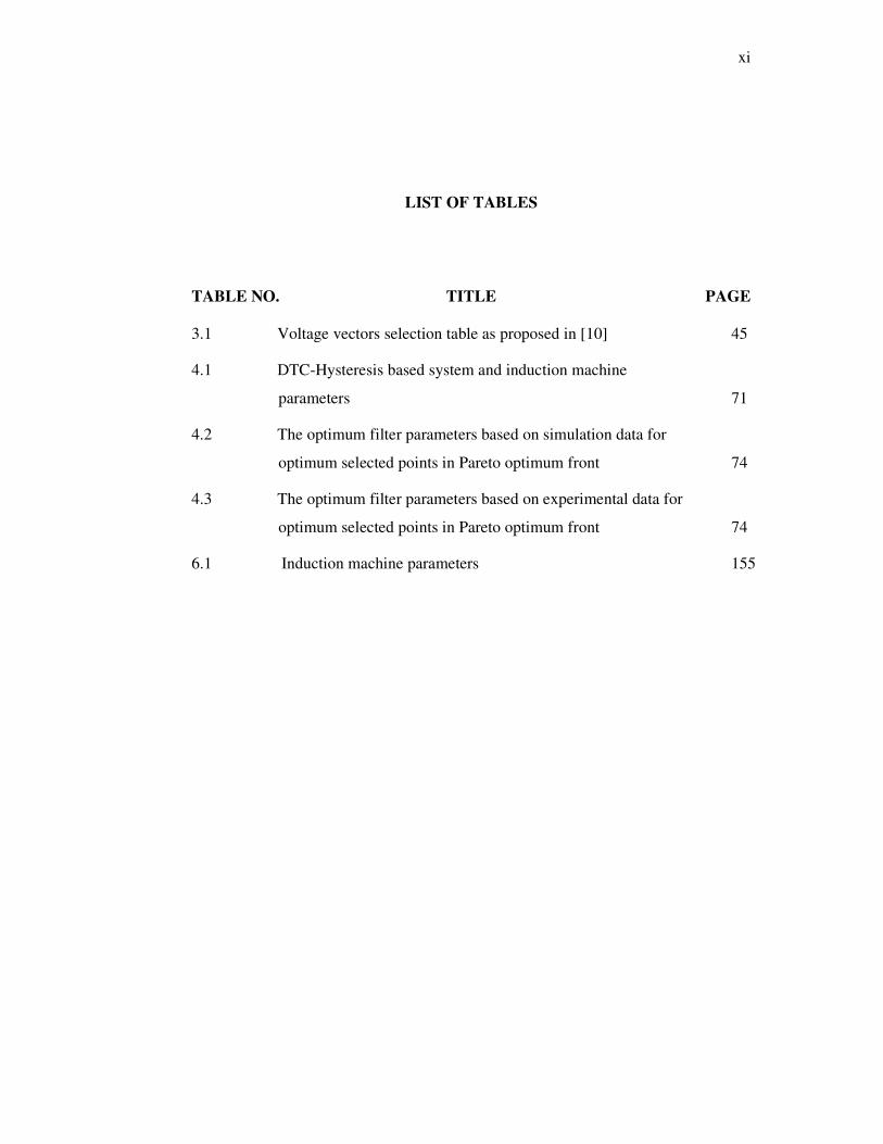
LIST OF TABLES
TABLE NO. TITLE PAGE
3.1 Voltage vectors selection table as proposed in [10] 45
4.1 DTC-Hysteresis based system and induction machine
parameters 71
4.2 The optimum filter parameters based on simulation data for
optimum selected points in Pareto optimum front 74
4.3 The optimum filter parameters based on experimental data for
optimum selected points in Pareto optimum front 74
6.1 Induction machine parameters 155

xii
LIST OF FIGURES
FIGURE NO. TITLE PAGE
1.1 Classification of variable frequency drives for IM control [7] 2
1.2 Closed loop IM with constant V / Hz variable frequency
drive 3
1.3 Fundamental direct FOC technique with an observer used for
rotor flux estimation 5
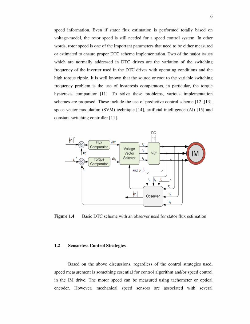
1.4 Basic DTC scheme with an observer used for stator flux
estimation 6
2.1 Sensorless estimation techniques for induction motor 12
2.2 Cross-section of a single pole-pair three-phase machine 13
2.3 A space vector x in the three-phase symmetric system (based
on (2.1)) 15
2.4 Model reference adaptive system for speed estimation 20
2.5 Adaptive observer for speed estimation 22
2.6 Structure of extended Kalman filter 25
2.7 Sliding mode observer for speed estimation 26
2.8 FOC drive with speed estimation based on parasitic effects 29
3.1 Schematic diagram of Voltage Source Inverter connected to
IM 33
3.2 Voltage space vectors of a 3-phase inverter with the
corresponded switching states 34

xiii
3.3 Control of flux magnitude using a 2-level hysteresis
comparator 35
3.4 Typical waveforms of the stator flux, the flux error and the
flux error status for the two-level hysteresis flux comparator 36
3.5 Definition of six sectors of the stator flux plane 37
3.6 Two possible active voltages are switched for each sector to
control the stator flux within its hysteresis band 37
3.7 The variation of δsr with application of (a) active voltage
vector, (b) zero or radial voltage vector, (c) reverse voltage
vector. 39
3.8 The application of voltage vectors in controlling the δsr as
well as the output torque for 4-quadrant operation 41
3.9 Control of torque using a 3-level hysteresis comparator 43
3.10 Typical waveforms of the torque, the torque error and the
torque error status for the three-level hysteresis torque
comparator 44
3.11 de-coupled control structure of DTC-hysteresis based
induction machine 45
3.12 Structure of extended Kalman filter 53
3.13 Complete structure of EKF-based DTC of IM 54
4.1 The flow program for optimizing EKF using NSGA II 60
4.2 Voltage and current training profiles obtained from
simulation for optimizing the EKF parameters using NSGA II 62
4.3 Voltage and current training profiles obtained from
experimentation for optimizing the EKF parameters using
NSGA II 63
4.4 Speed and torque target profiles obtained from simulation for
optimizing the EKF parameters using NSGA II 64
xiv
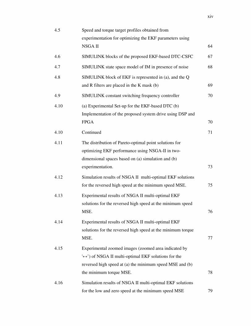
4.5 Speed and torque target profiles obtained from
experimentation for optimizing the EKF parameters using
NSGA II 64
4.6 SIMULINK blocks of the proposed EKF-based DTC-CSFC 67
4.7 SIMULINK state space model of IM in presence of noise 68
4.8 SIMULINK block of EKF is represented in (a), and the Q
and R filters are placed in the K mask (b) 69
4.9 SIMULINK constant switching frequency controller 70
4.10 (a) Experimental Set-up for the EKF-based DTC (b)
Implementation of the proposed system drive using DSP and
FPGA 70
4.10 Continued 71
4.11 The distribution of Pareto-optimal point solutions for
optimizing EKF performance using NSGA-II in two-
dimensional spaces based on (a) simulation and (b)
experimentation. 73
4.12 Simulation results of NSGA II multi-optimal EKF solutions
for the reversed high speed at the minimum speed MSE. 75
4.13 Experimental results of NSGA II multi-optimal EKF
solutions for the reversed high speed at the minimum speed
MSE. 76
4.14 Experimental results of NSGA II multi-optimal EKF
solutions for the reversed high speed at the minimum torque
MSE. 77
4.15 Experimental zoomed images (zoomed area indicated by
'↔’) of NSGA II multi-optimal EKF solutions for the
reversed high speed at (a) the minimum speed MSE and (b)
the minimum torque MSE. 78
4.16 Simulation results of NSGA II multi-optimal EKF solutions
for the low and zero speed at the minimum speed MSE 79
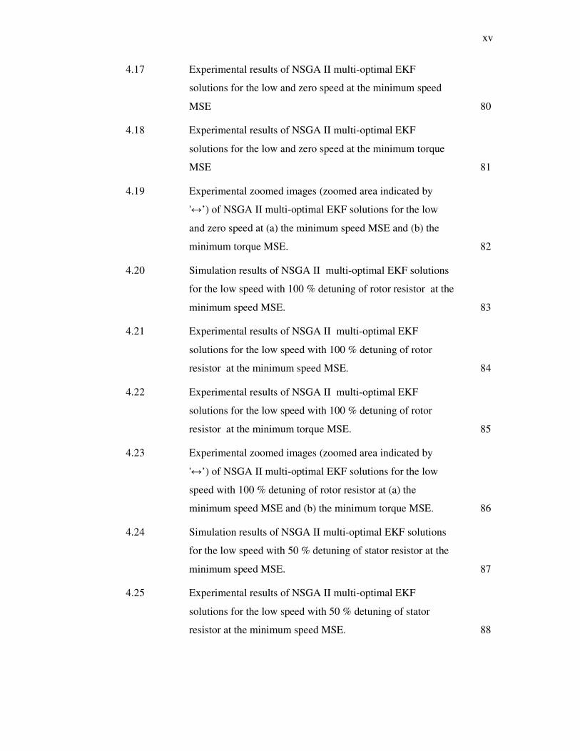
xv
4.17 Experimental results of NSGA II multi-optimal EKF
solutions for the low and zero speed at the minimum speed
MSE 80
4.18 Experimental results of NSGA II multi-optimal EKF
solutions for the low and zero speed at the minimum torque
MSE 81
4.19 Experimental zoomed images (zoomed area indicated by
'↔’) of NSGA II multi-optimal EKF solutions for the low
and zero speed at (a) the minimum speed MSE and (b) the
minimum torque MSE. 82
4.20 Simulation results of NSGA II multi-optimal EKF solutions
for the low speed with 100 % detuning of rotor resistor at the
minimum speed MSE. 83
4.21 Experimental results of NSGA II multi-optimal EKF
solutions for the low speed with 100 % detuning of rotor
resistor at the minimum speed MSE. 84
4.22 Experimental results of NSGA II multi-optimal EKF
solutions for the low speed with 100 % detuning of rotor
resistor at the minimum torque MSE. 85
4.23 Experimental zoomed images (zoomed area indicated by
'↔’) of NSGA II multi-optimal EKF solutions for the low
speed with 100 % detuning of rotor resistor at (a) the
minimum speed MSE and (b) the minimum torque MSE. 86
4.24 Simulation results of NSGA II multi-optimal EKF solutions
for the low speed with 50 % detuning of stator resistor at the
minimum speed MSE. 87
4.25 Experimental results of NSGA II multi-optimal EKF
solutions for the low speed with 50 % detuning of stator
resistor at the minimum speed MSE. 88

xvi
4.26 Experimental results of NSGA II multi-optimal EKF
solutions for the low speed with 50 % detuning of stator
resistor at the minimum torque MSE. 89
4.27 Experimental zoomed images (zoomed area indicated by
'↔’) of NSGA II multi-optimal EKF solutions for the low
speed with 50 % detuning of stator resistor at (a) the
minimum speed MSE and (b) the minimum torque MSE. 90
4.28 Simulation results of multi-optimal EKF solutions at low
reversed speed with a slow triangular motion and applied
load at the minimum speed MSE. 91
4.29 Experimental results of multi-optimal EKF solutions at low
reversed speed with a slow triangular motion and applied
load at the minimum speed MSE. 92
4.30 Experimental results of multi-optimal EKF solutions at low
reversed speed with a slow triangular motion and applied
load at the minimum torque MSE. 93
4.31 Experimental zoomed images (zoomed area indicated by
'↔’) of NSGA II multi-optimal EKF solutions for the
reversed low speed with applied load at (a) the minimum
speed MSE and (b) the minimum torque MSE. 94
5.1 Constant frequency torque controller 99
5.2 Typical waveforms of the constant frequency torque
controller 99
5.3 Generated upper triangular waveform using DSP (sampled at
DT µs) 100
5.4 Averaged and linearized torque loop (as proposed in [11]) 102
5.5 The generated upper triangle waveform of CSF with a sample
time of 120 µs 104
5.6 Bode plot of loop gain with PI controller for the proposed
CSFC 105
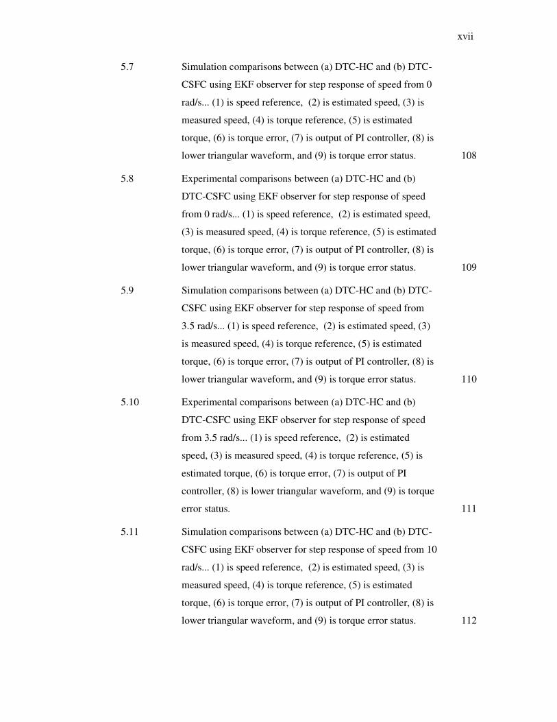
xvii
5.7 Simulation comparisons between (a) DTC-HC and (b) DTC-
CSFC using EKF observer for step response of speed from 0
rad/s... (1) is speed reference, (2) is estimated speed, (3) is
measured speed, (4) is torque reference, (5) is estimated
torque, (6) is torque error, (7) is output of PI controller, (8) is
lower triangular waveform, and (9) is torque error status. 108
5.8 Experimental comparisons between (a) DTC-HC and (b)
DTC-CSFC using EKF observer for step response of speed
from 0 rad/s... (1) is speed reference, (2) is estimated speed,
(3) is measured speed, (4) is torque reference, (5) is estimated
torque, (6) is torque error, (7) is output of PI controller, (8) is
lower triangular waveform, and (9) is torque error status. 109
5.9 Simulation comparisons between (a) DTC-HC and (b) DTC-
CSFC using EKF observer for step response of speed from
3.5 rad/s... (1) is speed reference, (2) is estimated speed, (3)
is measured speed, (4) is torque reference, (5) is estimated
torque, (6) is torque error, (7) is output of PI controller, (8) is
lower triangular waveform, and (9) is torque error status. 110
5.10 Experimental comparisons between (a) DTC-HC and (b)
DTC-CSFC using EKF observer for step response of speed
from 3.5 rad/s... (1) is speed reference, (2) is estimated
speed, (3) is measured speed, (4) is torque reference, (5) is
estimated torque, (6) is torque error, (7) is output of PI
controller, (8) is lower triangular waveform, and (9) is torque
error status. 111
5.11 Simulation comparisons between (a) DTC-HC and (b) DTC-
CSFC using EKF observer for step response of speed from 10
rad/s... (1) is speed reference, (2) is estimated speed, (3) is
measured speed, (4) is torque reference, (5) is estimated
torque, (6) is torque error, (7) is output of PI controller, (8) is
lower triangular waveform, and (9) is torque error status. 112
xviii
5.12 Experimental comparisons between (a) DTC-HC and (b)
DTC-CSFC using EKF observer for step response of speed
from 10 rad/s... (1) is speed reference, (2) is estimated speed,
(3) is measured speed, (4) is torque reference, (5) is estimated
torque, (6) is torque error, and (7) is output of PI controller,
(8) is lower triangular waveform, and (9) is torque error
status. 113
5.13 Experimental zoomed images (zoomed area indicated by
'↔’) of the output of PI controller and upper triangular
waveform for reference speed change from (a) 0 rad/s , (b)
3.5 rad/s, and (c) 10 rad/s 114
5.14 Simulation results at high reversed speed operation using
EKF for DTC-HC. 115
5.15 Experimental results at high reversed speed operation using
EKF for DTC-HC. 116
5.16 Simulation results at high reversed speed operation using
EKF for DTC-CSFC. 117
5.17 Experimental results at high reversed speed operation using
EKF for DTC-CSFC. 118
5.18 Simulation results at low and zero speed operation using EKF
for DTC-HC. 119
5.19 Experimental results at low and zero speed operation using
EKF for DTC-HC. 120
5.20 Simulation results at low and zero speed operation using EKF
for DTC-CSFC. 121
5.21 Experimental results at low and zero speed operation using
EKF for DTC-CSFC. 122
5.22 Simulation zoomed images (zoomed area indicated by '↔’)
of the speed , torque, flux and current (a) waveforms at low
and zero speed for DTC-HC. 123

xix
5.23 Experimental zoomed images (zoomed area indicated by
'↔’) of the speed , torque, flux and current (a) waveforms at
low and zero speed for DTC-HC. 124
5.24 Simulation zoomed images (zoomed area indicated by '↔’)
of the speed , torque, flux and current (a) waveforms at low
and zero speed for DTC-CSFC. 125
5.25 Experimental zoomed images (zoomed area indicated by
'↔’) of the speed, torque, flux and current (a) waveforms at
low and zero speed for DTC-CSFC. 126
5.26 Simulation results at slow triangular speed operation using
EKF for DTC-HC. 127
5.27 Experimental results at slow triangular speed operation using
EKF for DTC-HC. 128
5.28 Simulation results at slow triangular speed operation using
EKF for DTC-CSFC. 129
5.29 Experimental results at slow triangular speed operation using
EKF for DTC-CSFC. 130
5.30 Simulation results at slow triangular speed operation under
load using EKF for DTC-HC. 131
5.31 Experimental results at slow triangular speed operation under
load using EKF for DTC-HC. 132
5.32 Simulation results at slow triangular speed operation under
load using EKF for DTC-CSFC. 133
5.33 Experimental results at slow triangular speed operation under
load using EKF for DTC-CSFC. 134
5.34 Simulation results at high speed operation under step load
using EKF for DTC-HC. 135
5.35 Experimental results at high speed operation under step load
using EKF for DTC-HC. 136
xx
5.36 Simulation results at high speed operation under step load
using EKF for DTC-CSFC. 137
5.37 Experimental results at high speed operation under step load
using EKF for DTC-CSFC. 138
6.1 Complete drive system; (a) picture of the experiment set-up,
(b) functional block diagram of the experiment set-up...(1)
Motor DC power supply, (2) Capacitor, (3) VSI, (4) Current
sensor, (5) Oscilloscope, (6) DS1104 Controldesk interface,
(7) IM, (8) Torque transducer, (9) Hysteresis brake . 141
6.2 Identifying sectors of the stator flux (a) definition of Ψsq,1, (b)
determining sector based on threshold values, i.e. 0 and Ψsq,1 144
6.3 FPGA (Basys2) 146
6.4 Block diagram of voltage vector selection table and blanking
time generation using FPGA (Basys2) 148
6.5 Block diagram of blanking time generation for a single leg
(i.e. phase a) 148
6.6 Timing diagram of blanking time generation for a single leg
(i.e. phase a) 149
6.7 Schematic of the gate driver circuit 150
6.8 Schematic of the IGBT module with the capacitor snubbers 151
6.9 Schematic of the gate driver circuit 151
6.10 Complete drive train couplings (a) picture of the drive train,
(b) functional block diagram of the drive train 153
6.10 Continued 154

xxi
LIST OF ABBREVIATIONS
AC - Alternating Current
ADC - Analog to digital converter
B - Input matrix
BPF - Band pass filter
CFTC - Constant Frequency Torque Controller
Clower - Lower triangular carrier
Cp-p - Peak to peak value of the triangular carrier
Cupper - Upper triangular carrier
d,q - Direct and quadrature axis of the stationary reference frame
DAC - Digital to analog converter
DC - Direct Current
DSP - Digital Signal Processor
DTC - Direct Torque Control
dΨs
,
qΨs
- Direct and quadrature axis of the estimated stator flux reference
frame
EKF - Extended Kalman filter
emf - Electromotive force
fc - Carrier frequency
FOC - Field Oriented Control
FPGA - Field Programmable Gate Array
I.E - Incremental Encoder
I.M - Induction Machine
ird, irq - d and q components of the rotor current in stationary reference
frame
is, ir - Stator and rotor current space vectors in stationary reference
frame
isd, isq - d and q components of the stator current in stationary reference
frame
isg , ir
g - Stator and rotor current space vectors in general reference
frame
J - Moment of inertia
KF - Kalman filter
ki - Integral gain of the PI controller
kp - Proportional gain of the PI controller
xxii
Lm - Mutual inductance
LPF - Low pass filter
Lr - Rotor self-inductance
Ls - Stator self-inductance
MRAS - Model reference adaptive system
P - Number of pole pairs
p.p.r - Pulse per revolution
PI - Proportional - Integral
PWM - Pulse Width Modulation
PWM - Pulse-width modulation
r.m.s - Root mean squared
Rs, Rr - Stator and rotor resistance
Sa, Sb,
Sc
- Switching states of phase a, b, c
SI - Signal injection
SMO - Sliding mode observer
SNR - Signal to noise ratio
SVM - Space Vector Modulation
Tc - Output of PI controller for the CFTC
Te - Electromagnetic torque
Te,rated - Torque rated
Te,ref
- Reference torque
Tstat - Torque error status
ttri - Period of Cupper or Clower
u - Control-input vector
VDC - DC link voltage
VFD - Variable frequency drives
VHDL - VHSIC hardware description language
vs - Stator voltage space vector in stationary reference frame
VSD - Variable speed drives
vsd, vsq - d and q components of the stator voltage in stationary reference
frame
vsg - Stator voltage space vector in general reference frame
VSI - Voltage Source Inverter
δsr - Difference angle between stator flux linkage and rotor flux
linkage
θr - Angle with respect to rotor axis
θs - Angle with respect to stator axis
σ - Total flux leakage factor
τr - Rotor time constant
Ψs - Estimated stator flux linkage

xxiii
Ψs g,
Ψrg
- Stator and rotor flux linkage space vectors in general reference
frame
Ψs, Ψr - Stator and rotor flux linkage space vectors in stationary
reference frame
Ψsd Ψs
,
Ψsq Ψs
- d and q components of stator flux in stator flux reference frame
Ψsd,
Ψsq
- d and q components of stator flux in stationary reference frame
ωe - Steady state synchronous frequency in rad./s
ωm - Rotor mechanical speed in rad./s
ωr - Rotor electrical speed in rad./s
ωslip - Steady state slip frequency in rad./s
xxiv
LIST OF APPENDICES
APPENDIX NO. TITLE PAGE
A Derivation of torque and flux equations 176
B Simulation of EKF-based DTC 178
C EKF MATLAB coding for multi-objective optimization 185
D DSP source code for EKF-based DTC 188
E List of publications 202
CHAPTER 1
INTRODUCTION
1.1 Overview of Induction Motor Drives
Induction motors (IMs) dominate the world market (more than 85% of
electrical motors)[1] with broad applications in industries, public services and
household electrical appliances [2-3]. The popularity of IMs is mainly due to their
low cost, ruggedness, high reliability, and minimum maintenance [4]. The induction
machines began to gradually replace DC machines in many industrial applications as
the Field Oriented Control (FOC) introduced by F. Blachke in 1970’s can produce
comparable performance to that obtained in DC machines [5]. Moreover, their
popularity is also assisted by the rapid development in power semiconductor devices
and the emergence of high-speed microprocessor and digital signal processors [6].
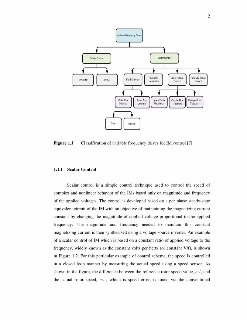
Much of the previous research has been devoted to improving the drive
systems of the IM, especially the control methodology. The advent of power
semiconductor switches and digital control technology has led to remarkable
improvements in the variable frequency drives (VFDs) i.e. providing smoother speed
tuning, greater motor control, and fewer energy losses. Based on the torque and
speed control techniques, the IM-VFDs can be classified into two main categories
namely the scalar and vector control methods, as illustrated in Figure 1.1. A brief
discussion on these control methods are given as follows.
2
Figure 1.1 Classification of variable frequency drives for IM control [7]
1.1.1 Scalar Control
Scalar control is a simple control technique used to control the speed of
complex and nonlinear behavior of the IMs based only on magnitude and frequency
of the applied voltages. The control is developed based on a per phase steady-state
equivalent circuit of the IM with an objective of maintaining the magnetizing current
constant by changing the magnitude of applied voltage proportional to the applied
frequency. The magnitude and frequency needed to maintain this constant
magnetizing current is then synthesized using a voltage source inverter. An example
of a scalar control of IM which is based on a constant ratio of applied voltage to the
frequency, widely known as the constant volts per hertz (or constant V/f), is shown
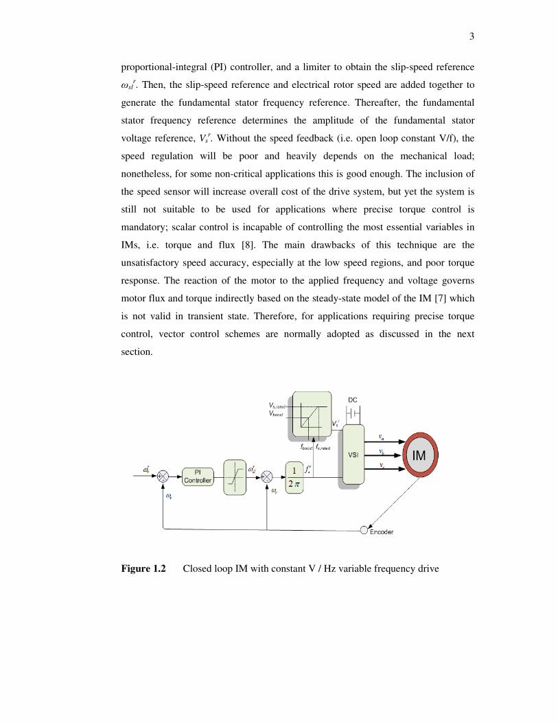
in Figure 1.2. For this particular example of control scheme, the speed is controlled
in a closed loop manner by measuring the actual speed using a speed sensor. As
shown in the figure, the difference between the reference rotor speed value, ωrr, and
the actual rotor speed, ωr , which is speed error, is tuned via the conventional
3
proportional-integral (PI) controller, and a limiter to obtain the slip-speed reference
ωslr. Then, the slip-speed reference and electrical rotor speed are added together to
generate the fundamental stator frequency reference. Thereafter, the fundamental
stator frequency reference determines the amplitude of the fundamental stator
voltage reference, Vsr. Without the speed feedback (i.e. open loop constant V/f), the
speed regulation will be poor and heavily depends on the mechanical load;
nonetheless, for some non-critical applications this is good enough. The inclusion of
the speed sensor will increase overall cost of the drive system, but yet the system is
still not suitable to be used for applications where precise torque control is
mandatory; scalar control is incapable of controlling the most essential variables in
IMs, i.e. torque and flux [8]. The main drawbacks of this technique are the
unsatisfactory speed accuracy, especially at the low speed regions, and poor torque
response. The reaction of the motor to the applied frequency and voltage governs
motor flux and torque indirectly based on the steady-state model of the IM [7] which
is not valid in transient state. Therefore, for applications requiring precise torque
control, vector control schemes are normally adopted as discussed in the next
section.
Figure 1.2 Closed loop IM with constant V / Hz variable frequency drive
4
1.1.2 Field Oriented Control (FOC)
Field oriented control (FOC) or vector control (VC) was introduced by Hasse
and Blaschke from Germany, in 1969 and 1971 respectively [7]. On the contrary to
the scalar control, the development of FOC control scheme is based on dynamic
model of the IM where the voltages, currents and fluxes are expressed in space
vector forms. The representation of the motor’s quantities using space vectors valid
under both steady state and transient conditions hence with FOC, excellent transient
response can be achieved. The rotor flux FOC scheme is based on the frame
transformation of all quantities to a rotating frame fixed to the rotor flux. In this
rotating rotor flux frame, all quantities rotating at synchronous speed will appear as
DC quantities. If the flux is aligned to the d axis of this reference frame, it can be
shown that the d and q components of the stator current represent the flux and torque
component respectively. This means that utilizing FOC, the control of IM is
transformed to a simple control scheme similar to the DC motor control where the
torque and flux components are decoupled. The way the rotor flux position is
obtained determines the type of FOC as either direct FOC or indirect FOC. In
indirect FOC, the flux position is obtained by adding the slip position to the
measured rotor position, whereas in direct FOC it is calculated (or can also be
measured) based on the terminal variables and rotor speed. Figure 1.3 shows the
block diagram of a direct rotor flux FOC with speed loop. The rotor speed, which is
obtained from the encoder, is used as the speed feedback and also more importantly
is used by the observer to calculate the rotor flux position. Alternatively, instead of
rotor flux orientation, it is also possible to perform the orientation to the stator flux –
which is known as stator flux FOC. It can be seen that in FOC scheme, the
knowledge of rotor position need to be acquired accurately in order to perform the
frame transformation. Inaccurate rotor flux position causes the torque and flux not to
be completely decoupled and consequently resulted in deterioration in the torque
dynamics [9].
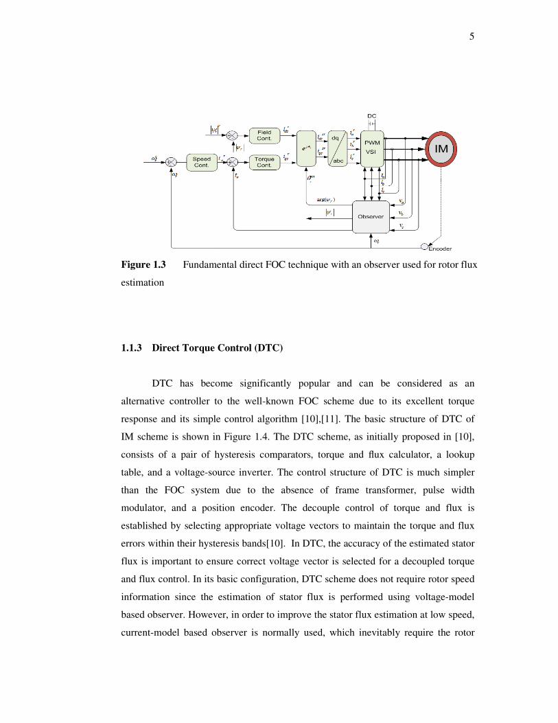
5
Figure 1.3 Fundamental direct FOC technique with an observer used for rotor flux
estimation
1.1.3 Direct Torque Control (DTC)
DTC has become significantly popular and can be considered as an
alternative controller to the well-known FOC scheme due to its excellent torque
response and its simple control algorithm [10],[11]. The basic structure of DTC of
IM scheme is shown in Figure 1.4. The DTC scheme, as initially proposed in [10],
consists of a pair of hysteresis comparators, torque and flux calculator, a lookup
table, and a voltage-source inverter. The control structure of DTC is much simpler
than the FOC system due to the absence of frame transformer, pulse width
modulator, and a position encoder. The decouple control of torque and flux is
established by selecting appropriate voltage vectors to maintain the torque and flux
errors within their hysteresis bands[10]. In DTC, the accuracy of the estimated stator
flux is important to ensure correct voltage vector is selected for a decoupled torque
and flux control. In its basic configuration, DTC scheme does not require rotor speed
information since the estimation of stator flux is performed using voltage-model
based observer. However, in order to improve the stator flux estimation at low speed,
current-model based observer is normally used, which inevitably require the rotor
6
speed information. Even if stator flux estimation is performed totally based on
voltage-model, the rotor speed is still needed for a speed control system. In other
words, rotor speed is one of the important parameters that need to be either measured
or estimated to ensure proper DTC scheme implementation. Two of the major issues
which are normally addressed in DTC drives are the variation of the switching
frequency of the inverter used in the DTC drives with operating conditions and the
high torque ripple. It is well known that the source or root to the variable switching
frequency problem is the use of hysteresis comparators, in particular, the torque
hysteresis comparator [11]. To solve these problems, various implementation
schemes are proposed. These include the use of predictive control scheme [12],[13],
space vector modulation (SVM) technique [14], artificial intelligence (AI) [15] and
constant switching controller [11].
Figure 1.4 Basic DTC scheme with an observer used for stator flux estimation
1.2 Sensorless Control Strategies
Based on the above discussions, regardless of the control strategies used,
speed measurement is something essential for control algorithm and/or speed control
in the IM drive. The motor speed can be measured using tachometer or optical
encoder. However, mechanical speed sensors are associated with several
7
disadvantages: The increased in the size and cost of the drive system, reduced
reliability and robustness, and regular maintenance of the speed sensor itself.
Furthermore, in some applications, it is inappropriate to install the mechanical speed
encoder at the motor shaft due to the physical and environment constraints.
Accordingly, increasing attempts have been made to eliminate the encoder mounted
at the motor shaft without affecting the performance of the VFD system. Hence,
research interests on sensorless techniques applied to IMs have grown dramatically
in the last few decades. Generally, the speed estimation techniques can be classified
into two broad categories: Estimation based on mathematical machine model and
estimation through signal injection to exploit the anisotropy of the machine as will be
discussed in Chapter 2.
1.3 Thesis Objectives and Contributions
The objective of this thesis is to develop a robust estimation method and
improve the performance of the speed sensorless DTC of induction motors for a wide
speed region, particularly persistent operation at and around zero speed. Despite the
improvements, the proposed techniques also aim to retain the simple control
structure of DTC drive. The thesis utilizes the simplicity of DTC to propose and
implement a powerful estimation technique of extended Kalaman filter (EKF) to
achieve a proper induction machine control employed in the DTC with a hysteresis
controller (for convenience, it is recognized as EKF-based DTC-HC) and DTC with
a constant frequency torque controller (for convenience, it is identified as EKF-based
DTC-CSFC) of induction machine i.e. to achieve a speed sensorless drive system, to
improve torque dynamic control, and to enhance speed estimation capability for a
wide speed operation. While doing the research, the thesis makes the following
contributions.
1) It offers an alternative method in tuning the EKF for the estimation
application of the squirrel cage IM. The main motivation is to reduce the
EKF structure complexity by eliminating unnecessary covariance matrices
8
as well as widening the time scale for the optimization process. Application
of the non-dominated sorting genetic algorithm II (NSGA II) method will be
carried out to investigate the optimization performance of estimated torque
besides the speed estimation. Indeed, this gives a systematic approach in
selecting filter solutions with known minimum squared errors (MSEs) for
the comparison purpose.
2) It analyses the effect of low and zero speed operation on the performance of
speed and torque in EKF-based DTC-HC and EKF-based DTC-CSFC
drives. Although the DTC is well established to give a high performance
torque control, there is still room to further improve the performance based
on the observation of the analysis.
1.4 Scope of Research
In order to achieve the objective of the research, the following scope of work
has been carried out:
A critical and comprehensive review of speed estimation methods. In this
review, the previous works on speed estimation methods used for induction machine
drives are addressed. Their strengths and drawbacks based on several evaluation
factors are highlighted. Besides giving the overview on the existing estimation
methods, the objective of the review is to look for a gap in the literature, particularly
on the issue of estimation at low speed region.
Modeling and simulation of the sensorless EKF-based DTC drive. In order to
accurately study the sensorless EKF-based DTC of IM, a good model of the
induction machine along with the proposed sensorless drive system is required. Thus,
the parameters of equivalent circuit of IM are extracted by testing motor under no-
load and locked rotor tests. A simple, fast and accurate modeling of overall system is
then developed with the usage of MATLAB/SIMULINK software package.

9
Development of a simple and fast platform to optimize EKF parameters. The
EKF was coded in MATLAB instead of using SIMULINK blocks where more time
needs to be consumed. Thus, larger time scale has been used to improve on the
optimization process.
The proposed speed estimation scheme utilizing a DTC drive have been
verified and evaluated for its feasibility and effectiveness through simulation and
hardware implementation. A processor and field programmable gate array devices
(DS1104 and Xilinx FPGA (Baysis2)) were used to implement the DTC drive
including the speed estimation strategy. A standard induction machine with suitable
loads and IGBT-based VSI had been used for this purpose.
1.5 Organization of the Thesis
This thesis is organized into seven chapters. Their contents are outlined as
follows:
Chapter 2 describes the mathematical modeling of induction machine.
Moreover, it provides an extensive review of speed and parameter adaptation
techniques. In this review, the recent development of estimation strategies are
reviewed based on two categories; mathematical machine model method and
estimation via signal injection strategy.
In Chapter 3, the basic principle of DTC of induction machines and the state
estimator using EKF observer are introduced. It first describes the main components
that make the structure of DTC followed with the conventional method (low pass
filter) for estimation flux and torque. For the sensorless IM drive, the speed of the
motor must be estimated and not measured. Therefore, the EKF algorithm is
introduced and discussed.

10
Chapter 4 presents the optimization process of the EKF based-DTC-CSFC.
At the beginning of the chapter, some background materials on the NSGA II and its
application on EKF optimization are addressed. Simulation and experimental results
on the proposed method are then presented.
Chapter 5 will look at the effect of implementation of EKF on the
performance of the DTC-HC and DTC-CSFC for speed estimation at wide speed,
including a zero speed region. A quick procedure to design a proper controller of
CFTC is presented. Based on the observation, EKF-based DTC-CFTC is able to
produce a persistent and stable zero speed operation. Simulation and experimental
results are presented to show the effectiveness of the proposed method.
Chapter 6 describes the laboratory experimental set-up to implement the
EKF-based DTC. The implementation of the tasks using DS1104 and Xilinx FPGA
(Baysis2) are given. Detailed descriptions of each hardware components are
provided.
Chapter 7 gives the conclusion of the thesis. Several suggestions are given
for possible directions of future work.
159
the proposed EKF-based DTC-CSFC can give superior dynamic performance when
there is a step change from a zero speed zone to higher speed regions. Furthermore,
the proposed speed sensorless DTC drive was capable of reducing torque ripple and
producing constant switching frequency. The effectiveness of the proposed EKF-
based DTC-CSFC in providing wider speed estimation and higher torque capability
was verified by simulations and experiments as well as the comparison with the
EKF-based DTC with the hysteresis torque controller.
The challenge for EKF experimental implementation is the derivation of the
Jacobian matrices which require sufficiently small time intervals for linearization. In
order to achieve small step intervals, some of the main tasks of the DTC (i.e. look-up
table and blanking time) are implemented utilizing a Xilinx FPGA (Baysis2), this
way; the DSP (DSPACE 1104) is able to execute the EKF-based DTC algorithm
including the CSFC at the minimum sampling period of 120 µs.
7.2 Future Work
In this thesis, several contributions are presented. However, there remain
potentially new findings in the area of EKF optimization and EKF-based DTC
control that can still be explored. These can be summarized in the following section.
a) Incorporating the parameter compensation. In spite of the
robustness of the EKF filter against parameter variations, the
robustness comes to an end at a certain value. Therefore, it is
suggested to incorporate parameter adaptation to compensate for the
parameter variation which leads to more stability of the proposed
drive system.
b) Performing the CFSC and flux hysteresis calculation in the
FPGA. The triangular waveforms for the proposed CSFC are
generated by the DSPACE 1104 with a sampling period of 120 µs.
160
Since the triangular waveform is generated by software, its frequency
and the torque loop bandwidth are restricted by the sampling time of
the DSP controller. Enlargement of the triangular frequency can be
achieved if the CFSC is performed in the FPGA with higher
frequency leading to great reduction of torque ripple. In addition, this
can enhance the linearization of Jacobian matrices of EKF by
achieving smaller step intervals; hence, enhancing the stability of
EKF and improving the estimation of flux, torque, and speed.
c) Replacing the hysteresis based flux controller with a fixed
switching frequency controller. In this thesis, the proposed method
only utilizes the CSFC for the torque loop. In order for the stator flux
error switching to be independent of the speed variation, it is
suggested to replace the flux hysteresis comparator of DTC with
CSFC.
d) Applying other multi-objective swarm and evolutionary
optimization techniques for EKF filter tuning. In the current work,
non-dominated sorting genetic algorithm II (NSGA II) was used to
optimize the EKF filter parameters for speed and torque estimations.
However, there are still other multi-objective techniques that have
not been exploited for EKF tuning purpose. It would be exciting to
explore the optimization capabilities of other techniques and then to
be compared with NSGA II. Additionally, multi-objective can be
applied not only for speed and torque, but can be used for speed and
stator and rotor resistor optimization.

REFERENCES
1. Saravanan, C., J. Sathiswar and S. Raja, Performance of Three Phase
Induction Motor using Modified Stator Winding. International Journal of
Computer Applications, 2012. 46(1): 1-4.
2. Chakraborty, A., Advancements in power electronics and drives in interface
with growing renewable energy resources. Renewable and Sustainable
Energy Reviews, 2011. 15(4): 1816-1827.
3. Saidur, R., S. Mekhilef, M.B. Ali, A. Safari and H.A. Mohammed,
Applications of variable speed drive (VSD) in electrical motors energy
savings. Renewable and Sustainable Energy Reviews, 2012. 16(1): 543-550.
4. Amjad, S., S. Neelakrishnan and R. Rudramoorthy, Review of design
considerations and technological challenges for successful development and
deployment of plug-in hybrid electric vehicles. Renewable and Sustainable
Energy Reviews, 2010. 14(3): 1104-1110.
5. Blaschke, F., The Principle of Field-Orientation as applied to the New
Transvector Closed-Loop Control System for Rotating-Field Machines.
Siemens Review, 1972. 34: 217-220.
6. Gabriel, R. and W. Leonhard, Microprocessor control if induction motor., in
Proc. IEEE-IAS Int Semiconductor Power Conv Conf. 1982. p. 538-545.
7. Buja, G.S. and M.P. Kazmierkowski, Direct torque control of PWM inverter-
fed AC motors - a survey. IEEE Transactions on Industrial Electronics, 2004.
51(4): 744-757.
8. Martins, C.A. and A.S. Carvalho. Technological trends in induction motor
electrical drives. in IEEE Porto Power Tech Proceedings. 2001.
9. Vas, P., Sensorless Vector and Direct Torque Control. 1998, New York:
Oxford Univ. Press.
162
10. Takahashi, I. and T. Noguchi, A New Quick-Response and High-Efficiency
Control Strategy of an Induction Motor. IEEE Trans. Ind. App., 1986. IA-
22(5): 820-827.
11. Idris, N.R.N. and A.H.M. Yatim, Direct torque control of induction machines
with constant switching frequency and reduced torque ripple. IEEE Trans.
Ind. Electron., 2004. 51(4): 758-767.
12. Geyer, T., G. Papafotiou and M. Morari, Model Predictive Direct Torque
Control—Part I: Concept, Algorithm, and Analysis. IEEE Trans. Ind.
Electron., 2009. 56(6): 1894-1905.
13. Geyer, T., Computationally Efficient Model Predictive Direct Torque
Control. IEEE Trans. Power Electron., 2011. 26(10): 2804-2816.
14. Gholinezhad, J. and R. Noroozian. Application of cascaded H-bridge
multilevel inverter in DTC-SVM based induction motor drive. in Proc. Int.
Conf. Power Electronics and Drive Systems Technology. 2012.
15. Mir, S. and M.E. Elbuluk. Precision torque control in inverter-fed induction
machines using fuzzy logic. in Proc. Int. Conf. Power Electronics Specialists.
1995.
16. Holtz, J., Sensorless Control of Induction Machines;With or Without Signal
Injection? IEEE Trans. Ind. Electron., 2006. 53(1): 7-30.
17. Gadoue, S.M., D. Giaouris and J.W. Finch, Sensorless Control of Induction
Motor Drives at Very Low and Zero Speeds Using Neural Network Flux
Observers. IEEE Transactions on Industrial Electronics, 2009. 56(8): 3029-
3039.
18. Finch, J.W. and D. Giaouris, Controlled AC Electrical Drives. IEEE Trans.
Ind. Electron., 2008. 55(2): 481-491.
19. Leonhard, W., Control of Electrical Drives. 1984, Berlin: Springer-Verlag.
20. Bose, B.K., Power Electronics and AC Drives. 1986, New Jersey: Prentice-
Hall.
21. Murphy, J.M.D. and F.G. Turnbull, Power Electronic Control of AC Motors.
1987, Oxford: Pergamon Press.
22. M. Barut, S. Bogosyan and M. Gokasan, Experimental Evaluation of Braided
EKF for Sensorless Control of Induction Motors. IEEE Transaction on
Industrial Electronics, 2008. 55(2): 620-632.
163
23. Maurizio, C., P. Marcello, C. Giansalvo and C. Grard-Andr, Sensorless
Control of Induction Machines by a New Neural Algorithm: The TLS EXIN
Neuron. IEEE Transactions on Industrial Electronics, 2007. 54(1): 127-149.
24. Fang-Zheng, P. and T. Fukao, Robust speed identification for speed-
sensorless vector control of induction motors. IEEE Transactions on Industry
Applications, 1994. 30(5): 1234-1240.
25. Maiti, S., C. Chakraborty, Y. Hori and M.C. Ta, Model Reference Adaptive
Controller-Based Rotor Resistance and Speed Estimation Techniques for
Vector Controlled Induction Motor Drive Utilizing Reactive Power. IEEE
Transactions on Industrial Electronics, 2008. 55(2): 594-601.
26. Karanayil, B., M.F. Rahman and C. Grantham, An implementation of a
programmable cascaded low-pass filter for a rotor flux synthesizer for an
induction motor drive. IEEE Trans. Power Electron., 2004. 19(2): 257-263.
27. Li, Y. and W. Qin. Low speed performence improvement of sensorless IM
control system based on MRAS and NN flux observers. in IEEE International
Conference on Intelligent Computing and Intelligent Systems (ICIS). 2010.
28. Orlowska-Kowalska, T. and M. Dybkowski, Stator-Current-Based MRAS
Estimator for a Wide Range Speed-Sensorless Induction-Motor Drive. IEEE
Transactions on Industrial Electronics, 2010. 57(4): 1296-1308.
29. Rashed, M., F. Stronach and P. Vas. A new stable MRAS-based speed and
stator resistance estimators for sensorless vector control induction motor
drive at low speeds. in 38th Industry Applications Conference, IAS Annual
Meeting. 2003.
30. Ravi Teja, A.V., C. Chakraborty, S. Maiti and Y. Hori, A New Model
Reference Adaptive Controller for Four Quadrant Vector Controlled
Induction Motor Drives. IEEE Transactions on Industrial Electronics, 2012.
59(10): 3757-3767.
31. Gadoue, S.M., D. Giaouris and J.W. Finch. A new fuzzy logic based
adaptation mechanism for MRAS sensorless vector control induction motor
drives. in 4th IET Conference on Power Electronics, Machines and Drives.
2008.
32. Sayouti, Y., A. Abbou, M. Akherraz and H. Mahmoudi. Sensor less low
speed control with ANN MRAS for direct torque controlled induction motor

164
drive. in International Conference on Power Engineering, Energy and
Electrical Drives (POWERENG). 2011.
33. Gadoue, S.M., D. Giaouris and J.W. Finch, MRAS Sensorless Vector Control
of an Induction Motor Using New Sliding-Mode and Fuzzy-Logic Adaptation
Mechanisms. IEEE Transaction on Energy Conversion, 2010. 25(2): 394-
402.
34. Cirrincione, M., M. Pucci, G. Cirrincione and G.A. Capolino, An adaptive
speed observer based on a new total least-squares neuron for induction
machine drives. IEEE Transaction on Industry application, 2006. 42(1): 89-
104.
35. Davari, S.A., D.A. Khaburi, W. Fengxiang and R.M. Kennel, Using Full
Order and Reduced Order Observers for Robust Sensorless Predictive
Torque Control of Induction Motors. IEEE Transactions on Power
Electronics, 2012. 27(7): 3424-3433.
36. Harnefors, L. and M. Hinkkanen, Complete Stability of Reduced-Order and
Full-Order Observers for Sensorless IM Drives. IEEE Transactions on
Industrial Electronics, 2008. 55(3): 1319-1329.
37. Kubota, H., K. Matsuse and T. Nakano, DSP-based speed adaptive flux
observer of induction motor. IEEE Transactions on Industry Applications,
1993. 29(2): 344-348.
38. Salmasi, F.R. and T.A. Najafabadi, An Adaptive Observer With Online Rotor
and Stator Resistance Estimation for Induction Motors With One Phase
Current Sensor. IEEE Trans. Energy Convers., 2011. 26(3): 959-966.
39. Barut, M., R. Demir, E. Zerdali and R. Inan, Real-Time Implementation of Bi
Input-Extended Kalman Filter-Based Estimator for Speed-Sensorless Control
of Induction Motors. IEEE Trans. Ind. Electron., 2012. 59(11): 4197-4206.
40. Buyamin, S. and J.W. Finch. Comparative Study on Optimising the EKF for
Speed Estimation of an Induction Motor using Simulated Annealing and
Genetic Algorithm. in IEEE Proc. IEMDC Conf. . 2007.
41. Alsofyani, I.M., N.R.N. Idris, T. Sutikno and Y.A. Alamri. An optimized
Extended Kalman Filter for speed sensorless direct troque control of an
induction motor. in Proc. Int. Power and Energy 2012.
165
42. Ozsoy, E.E., M. Gokasan and S. Bogosyan, Simultaneous rotor and stator
resistance estimation of squirrel cage induction machine with a single
extended kalman filter. Turkish Journal of Electrical Engineering and
Computer Sciences, 2010. 18(5): 853-863.
43. Gherram, K., K. Yazid and M. Menaa. Sensorless indirect vector control of
an induction motor by ANNs observer and EKF. in 18th Mediterranean
Conference on Control & Automation (MED). 2010.
44. Danan, S., L. Wenli, D. Lijun and L. Zhigang. Speed Sensorless Induction
Motor Drive Based on EKF and G-1 Model. in International Conference on
Computer Distributed Control and Intelligent Environmental Monitoring
(CDCIEM). 2011.
45. Lascu, C., I. Boldea and F. Blaabjerg, Very-low-speed variable-structure
control of sensorless induction machine drives without signal injection. IEEE
Transactions on Industry Applications, 2005. 41(2): 591-598.
46. Hajian, M., G.R. Arab Markadeh, J. Soltani and S. Hoseinnia, Energy
optimized sliding-mode control of sensorless induction motor drives. Energy
Conversion and Management, 2009. 50(9): 2296-2306.
47. Comanescu, M., An Induction-Motor Speed Estimator Based on Integral
Sliding-Mode Current Control. IEEE Transactions on Industrial Electronics,
2009. 56(9): 3414-3423.
48. Derdiyok, A., Speed-Sensorless Control of Induction Motor Using a
Continuous Control Approach of Sliding-Mode and Flux Observer. IEEE
Transactions on Industrial Electronics, 2005. 52(4): 1170-1176.
49. Ghanes, M. and Z. Gang, On Sensorless Induction Motor Drives: Sliding-
Mode Observer and Output Feedback Controller. IEEE Transactions on
Industrial Electronics, 2009. 56(9): 3404-3413.
50. Vieira, R.P., C.C. Gastaldini, R.Z. Azzolin and H.A. Grundling. Discrete-
time sliding mode approach for speed estimation of symmetrical and
asymmetrical induction machines. in 37th Annual Conference on IEEE
Industrial Electronics Society IECON. 2011.
51. Yongchang, Z., Z. Jianguo, X. Wei, H. Jiefeng, D.G. Dorrell and Z.
Zhengming. Speed sensorless stator flux oriented control of three-level
inverter-fed induction motor drive based on fuzzy logic and sliding mode
166
control. in 36th Annual Conference on IEEE Industrial Electronics Society
IECON. 2010.
52. Zaky, M.S., M. Khater, H. Yasin and S.S. Shokralla, Very low speed and zero
speed estimations of sensorless induction motor drives. Electric Power
Systems Research, 2010. 80(2): 143-151.
53. Zaky, M.S., M.M. Khater, S.S. Shokralla and H.A. Yasin, Wide-Speed-Range
Estimation With Online Parameter Identification Schemes of Sensorless
Induction Motor Drives. IEEE Transactions.on Industrial Electronics, 2009.
56(5): 1699-1707.
54. Bolognani, S., L. Peretti and M. Zigliotto, Parameter Sensitivity Analysis of
an ImprovedOpen-Loop Speed Estimate forInduction Motor Drives. IEEE
Transactions on Power Electronics, 2008. 23(4): 2127-2135.
55. Boussak, M. and K. Jarray, A high-performance sensorless indirect stator
flux orientation control of induction motor drive. IEEE Transactions on
Industrial Electronics, 2006. 53(1): 41-49.
56. de Santana, E.S., E. Bim and W.C. do Amaral, A Predictive Algorithm for
Controlling Speed and Rotor Flux of Induction Motor. IEEE Transactions on
Industrial Electronics, 2008. 55(12): 4398-4407.
57. Toliyat, H.A., M. Wlas and Z. Krzemiriski, Neural-Network-Based
Parameter Estimations of Induction Motors. IEEE Trans. Ind. Appl., 2008.
55(4): 1783-1794.
58. Guanghui, W., H.F. Hofmann and A. El-Antably, Speed-sensorless torque
control of induction machine based on carrier signal injection and smooth-
air-gap induction machine model. IEEE Transactions on Energy Conversion,
2006. 21(3): 699-707.
59. Giaouris, D., J.W. Finch, O.C. Ferreira, R.M. Kennel and G.M. El-Murr,
Wavelet Denoising for Electric Drives. IEEE Transactions on Industrial
Electronics, 2008. 55(2): 543-550.
60. Garcia, P., F. Briz, M.W. Degner and D. Diaz-Reigosa, Accuracy, Bandwidth,
and Stability Limits of Carrier-Signal-Injection-Based Sensorless Control
Methods. IEEE Transactions on Industry Applications, 2007. 43(4): 990-
1000.
167
61. Pineda-Sanchez, M., M. Riera-Guasp, J.A. Antonino-Daviu, J. Roger-Folch,
J. Perez-Cruz and R. Puche-Panadero, Diagnosis of Induction Motor Faults in
the Fractional Fourier Domain. IEEE Transactions on Instrumentation and
Measurement, 2010. 59(8): 2065-2075.
62. McNamara, D.M., B. Enayati and A.K. Ziarani. Sensorless speed
measurement of induction motors using an adaptive frequency-tracking
algorithm. in 34th Annual Conference of IEEE Industrial Electronics IECON
2008.
63. Keysan, O. and H. Bulent Ertan. Higher order rotor slot harmonics for rotor
speed & position estimation. in 12th International Conference on
Optimization of Electrical and Electronic Equipment (OPTIM). 2010.
64. Staines, C.S., G.M. Asher and M. Sumner, Rotor-position estimation for
induction machines at zero and low frequency utilizing zero-sequence
currents. IEEE Transactions on Industry Applications, 2006. 42(1): 105-112.
65. Zhi, G., T.G. Habetler, R.G. Harley and R.S. Colby, A Sensorless Rotor
Temperature Estimator for Induction Machines Based on a Current
Harmonic Spectral Estimation Scheme. IEEE Transactions on Industrial
Electronics, 2008. 55(1): 407-416.
66. Degner, M.W. and R.D. Lorenz, Using multiple saliencies for the estimation
of flux, position, and velocity in AC machines. IEEE Transactions on Industry
Applications, 1998. 34(5): 1097-1104.
67. Jansen, P.L. and R.D. Lorenz, Transducerless position and velocity
estimation in induction and salient AC machines. IEEE Transactions on
Industry Applications, 1995. 31(2): 240-247.
68. Holtz, J. Sensorless control of induction motors-performance and limitations.
in Proceedings of the 2000 IEEE International Symposium on Industrial
Electronics (ISIE). 2000.
69. Jung-Ik, H. and S. Seung-Ki. Sensorless field orientation control of an
induction machine by high frequency signal injection. in Thirty-Second
Industry Applications Conference, IAS Annual Meeting. 1997.
70. Jung-Ik, H. and S. Seung-Ki. Physical understanding of high frequency
injection method to sensorless drives of an induction machine. in Industry
Applications Conference. 2000.
168
71. Purcell, A. and P. Acarnley, Device switching scheme for direct torque
control. Electronics Letters, 1998. 34(4): 412-414.
72. Bird, I.G. and H. Zelaya-De La Parra, Fuzzy logic torque ripple reduction for
DTC based AC drives. Electronics Letters, 1997. 33(17): 1501-1502.
73. MAYBECK, P.S., Stochastic Models, Estimation and Control. Vol. 141-1.
1979: Academic Pres.
74. KALMAN, R.E., A new approach to linear filtering and prediction problems.
Journal of Basic Engineering, 1960. 82(D): 35-45.
75. GREWAL, M.S. and A.P. ANDREWS, Kalman Filtering : theory and
practice using MATLAB. 2001, New York: Wiley.
76. Alsofyani, I.M. and N.R.N. Idris, A review on sensorless techniques for
sustainable reliablity and efficient variable frequency drives of induction
motors. Renewable and Sustainable Energy Reviews, 2013. 24(0): 111-121.
77. Shi, K.L., T.F. Chan, Y.K. Wong and S.L. Ho, Speed estimation of an
induction motor drive using an optimized extended Kalman filter. IEEE
Trans. Ind. Electron., 2002. 49(1): 124-133.
78. Winston, W., Operations Research: Applications and Algorithms. 1994,
Belmont, California: Duxbury Press.
79. Deb, K., A. Pratap, S. Agarwal and T. Meyarivan, A fast and elitist
multiobjective genetic algorithm: NSGA-II. IEEE Transactions on
Evolutionary Computation, 2002. 6(2): 182-197.
80. Barut, M., S. Bogosyan and M. Gokasan, Speed-Sensorless Estimation for
Induction Motors Using Extended Kalman Filters. IEEE Trans. Ind.
Electron., 2007. 54(1): 272-280.
81. Barut, M., S. Bogosyan and M. Gokasan, Experimental Evaluation of
Braided EKF for Sensorless Control of Induction Motors. IEEE Trans. Ind.
Electron., 2008. 55(2): 620-632.


