OPTIMAL SUNSHADE CONFIGURATIONS FOR SPACE- BASED GEOENGINEERING NEAR THE SUN-EARTH L1 POINT Joan-Pau Sánchez & Colin McInnes Climate Engineering Conference Berlin, Germany August 18-21, 2014
Transcript
OPTIMAL SUNSHADE CONFIGURATIONS FOR SPACE-BASED GEOENGINEERING NEAR THE SUN-EARTH L1 POINT
Joan-Pau Sánchez & Colin McInnes
Climate Engineering ConferenceBerlin, Germany
August 18-21, 2014
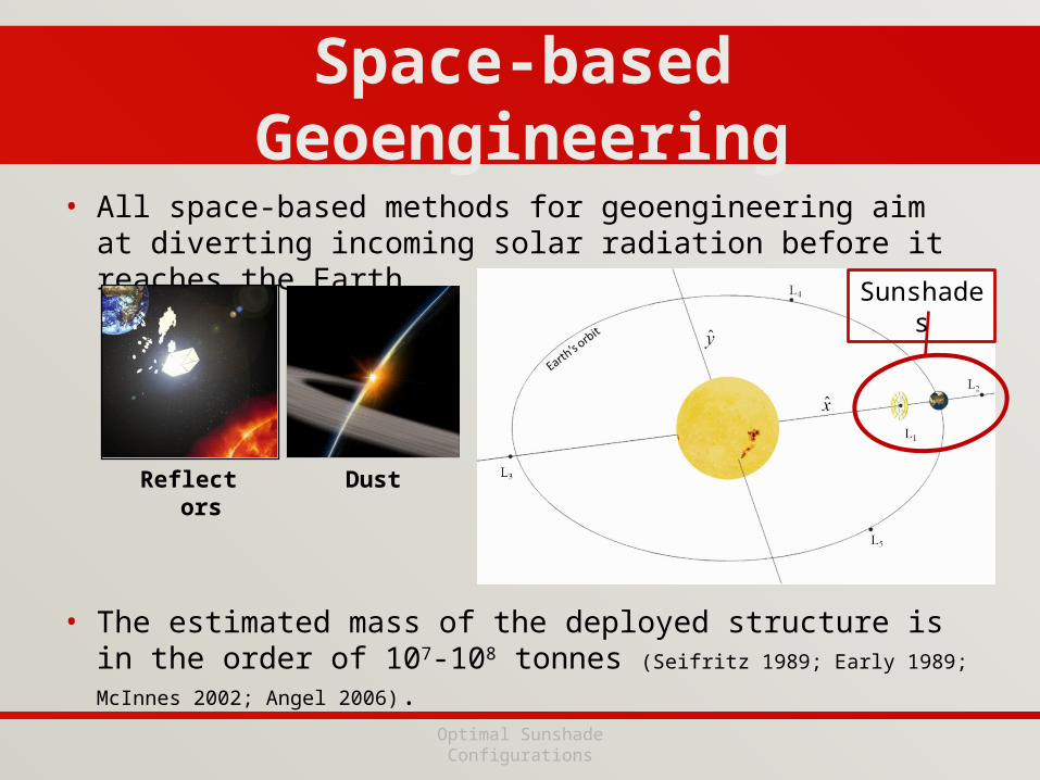
• All space-based methods for geoengineering aim at diverting incoming solar radiation before it reaches the Earth.
• The estimated mass of the deployed structure is in the order of 107-108 tonnes (Seifritz 1989; Early 1989; McInnes 2002; Angel 2006).
Space-based Geoengineering
Optimal Sunshade Configurations
Reflectors Dust
Sunshades
Optimal Sunshade Configurations for Space-based Geoengineering near the Sun-Earth L1 point
Optimal Sunshade Configurations
• Revisiting the concept of deploying a large sunshade at L1.– Most of the previous work aims at a uniform reduction of the solar
insolation by 1.7%.
• Problem: a uniform insolation reduction of 1.7% would drive important changes to regional climates (Lunt et al. 2008).– Warming at high latitudes and cooling at the tropics.
• Goal: optimal configurations of sunshades that offset regional differences such as latitudinal and seasonal difference of temperature.
S=1367 W/m2
ΔS=23.24 W/m2Disk
Diskd S
R Rd S
1,489 DiskR km
*at the SRP-displaced equilibrium point
Table of Contents
GREB
Optimization
Results
Understanding of regional effects of climate change, while performing a numerically intensive search.
GREB model (Dommenget and Floter 2011)
• Globally Resolved Energy Balance model (GREB) provides an insight of the effects of altering the incoming solar insolation into the Earth’s climate system.
– GREB captures only the main physical processes by means of simplified models. It assumes fixed atmospheric circulation, cloud cover and soil moisture, which are given as boundary conditions.
• Simple and fast
2xCO2 Scenario2xCO2+Sunshade Scenario
• 2xCO2 (680 ppm) + static sunshade at L1
– An iterative secant approach is used to find the size of the disk that yields a global mean temperature of 14 Co.
Classical In-line Scenario
3D Energy Kick Function
1,434 DiskR km
Sun
EarthL1
L2
z
y
x
ˆω z
*ΔT difference with respect the control scenario (1xCO2 world)
Shade Patterns
• A static sunshade at L1 casts an almost uniform shade onto the Earth.
• By displacing the occulting disk, different shade patterns are achieved.
Sun
EarthL1L2
z
y
x
ˆω z
Sun
EarthL1
L2
z
y
x
ˆω z
7,000 kmz
Are there perhaps more suitable disk configurations that can reduce the impact of climate change further than what the Sun-Earth in-line configuration achieved?
A Multiple-Objective Optimization• More suitable disk configurations that reduce the impact of climate at
regional and seasonal scale?
Sun
EarthL1
L2
z
y
x
ˆω z
– 2 Mirrors of Shading areas A1 and A2
– 2 sinusoidal and displaced out-of-plane motions.
1 1 1 1sinz t a t c b
2 2 2 2sinz t a t c b
1 1 1 1 2 2 2 2A a b c A a b cxDesign Variables
1 2A A J f
Criteria Vector
Total Shading AreaGeoengineering
Performance Index
A Multiple-Objective Optimization• More suitable disk configurations that reduce the impact of climate at
regional and seasonal scale?– 2 Mirrors of Shading areas A1 and A2
– 2 sinusoidal and displaced out-of-plane motions.
1 1 1 1 2 2 2 2A a b c A a b cxDesign Variables
1 2A A J f
Criteria Vector
Total Shading AreaGeoengineering
Performance Index
Pareto Optimal Set
Geoengineering Performance Index
• Optimal sunshade configurations were sought that minimize J
– J is the root-mean-square difference of temperature with respect to the control scenario, averaged over the entire Earth’s surface.
– Return the largest fraction of Earth’s surface to a climate within ±0.1 Co
difference of the surface temperatures of that of the 1xCO2 world.
1:48
1:48
cos
cos
i f ii
ii
ii
J w T
w
if 0.1
0 if 0.1
AnnualRMS AnnualRMS oLat i Lat i
f i AnnualRMS oLat i
T T CT
T C
2 2 2
50 50 50
1, t , t ... , t
12th th th
AnnualRMSscenario
Jan Feb Dec
year year year
T
T T T
2 2:2 1, , ,GeoEng xCO xCOT t T t T t
1:96
, ,
,96
scenario jj
scenario
T t
T t
Multiple-objective Optimization Problem
• Pareto optimal design solutions that minimize both J and the total shading area At required for 2 sunshades.
1 2A A J f
1 1 1 1 2 2 2 2A a b c A a b cx
sinz t a t c b
J0 =0.325 Co Classical inline Sc.
½J0
Case I
Case II
Classical In-line Scenario
CASE I• A solution with At as in the
classical in-line geoengineering solution. – J = 0,275 Co
– Improvement of 0.05oC.– Case I returns nearly 40% of the
Earth surface to pre-global warming temperatures, while the classical geoengineering scenario achieves less than 10%.
1 1,200 mR k
2 790 mR k
CASE I• The motion required cannot be
generated with the natural periodic motion that exist near L1. – Specific control law are thus
required.
CASE II• Minimum At to achieve ½·J0
– 1.5 times the At of the classical inline geoengineering solution.
– J = 0,162 Co
– Environmental risk is reduced to a quarter.
1 1,522 mR k
2 880 mR k
Conclusions
• This work provides new insights into the possibilities offered by space-based geoengineering using orbiting solar reflectors.
• Optimal configurations of orbiting sunshades were investigated that not only offset a global temperature increase, but also mitigate regional differences such as latitudinal and seasonal difference of monthly mean surface temperature.
• Two configurations of two orbiting occulting disks were presented that achieve clear gains with respect to a static disk near the Sun-Earth L1 point.
3D Energy Kick Function
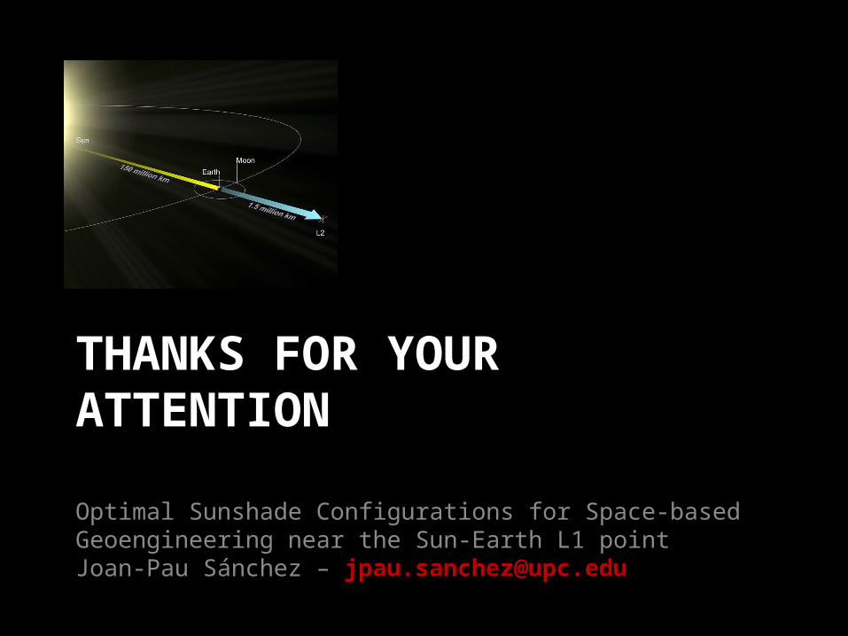
THANKS FOR YOUR ATTENTION
Optimal Sunshade Configurations for Space-based Geoengineering near the Sun-Earth L1 pointJoan-Pau Sánchez – [email protected]
APPENDIX
Optimal Sunshade Configurations
Space-based Geoengineering
Optimal Sunshade Configurations
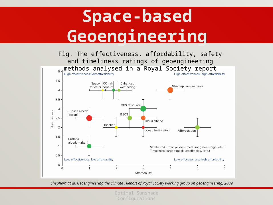
Fig. The effectiveness, affordability, safety and timeliness ratings of geoengineering methods analysed in a Royal Society report
Shepherd at al. Geoengineering the climate , Report of Royal Society working group on geoengineering, 2009
Optimal Configuration for Sun-Earth L1 Occulting Disk
Sun
EarthL1
L2
z
y
x
ˆω z
7,000 kmz (McInnes et al. 1994)
Libration Point Orbits
Shade Patterns
Sun
EarthL1
L2
z
y
x
ˆω z
7,000 kmz
Libration Point Orbits
• A static sunshade at L1 casts an almost uniform shade onto the Earth.
Sun
EarthL1
L2
z
y
x
ˆω z
• By displacing the occulting disk, different shade patterns are achieved.