The ratios of gas flow to steam flow are huge in heat recovery steam generators (HRSGs) compared to othersteam generators. So the volume which is occupied by components of the HRSG such as economizer, evapo-rator and superheater is important factor when the HRSG is applied in structures including buildings andships. The optimum volume of a HRSG is deduced through optimization of entropy generation and cost eval-uation. By increasing volume, second law of thermodynamics is improved, but this improvement may not beeconomical. In this work, the best dimensions and arrangements of flows in HRSG are obtained by constructaldesign and the optimization method is algorithm genetic. In this case, super heater temperature, pinch point,water/steam flow rate and gas pressure drop are derived from configuration which designed by constructaltheory for HRSG. The effects of gas flow rate and inlet gas temperature are examined on the values of opti-mum volume.
In last decades, depletion of fossil fuels is a critically important forhuman beings. Moreover, replacement energies, renewable energiesare economically less efficient than fossil fuels. In this case, optimizeduse of fossil fuels can be help. HRSG is an instrument to recover wasteheat from various industries. The HRSG is one of the most importantcomponents of the plant and its design affects to a large extent theefficiency and the cost of the whole plan. There are a number of stud-ies on the combined cycles and HRSGs, most of which focus on per-formance evaluation and efficiency improvement. M. Valdes et al.[1] represented a method for optimization of the HRSG in a com-bined cycle based on the application of influence coefficients. Themain advantage of the proposed method is that it permits a betterunderstanding the influence of the design parameters on the cycleperformance. C. casarosa et al. [2] represented that high efficiencycombined cycle depends on optimized matching components. Thethermodynamic optimization is based on the minimization of exergyloss, while the thermoeconomic optimization is based on theminimiza-tion of the total HRSG cost. A. Franco et al. [3] used a kind of compactheat exchanger to increase the efficiency and reduce the size of theunit. Omer F.can et al. [4] introduced a simplified energy, exergy andeconomical analysis of a cogeneration system, and the analysis was per-formed based on the measured data during the operation time of the
system. Further research works on the performance evaluation and op-timization of the HRSG have been done by several researchers duringthe three last decades [5–8].
Constructal law was stated by Adrian Bejan in 1996 as follows:“For a finite-size system to persist in time, it must evolve in such away that it provides easier access to the imposed currents that flowthrough it.” The morphing of structure is a result of the conflict be-tween the global objective and the global constraints. The first andsecond laws of thermodynamics speak of a black box, and they saynothing about the configuration (drawings) of systems. The constru-ctal law complements the existing principles (mass, momentum andenergy conservation and the second law of thermodynamics) andprovides new insights into finding the flow configuration. The config-uration emerges such that its performance is maximized by distribut-ing the flow resistance better and better through the availablevolume. The constructal law can be applied for any dissipative sys-tems, whether they are living or non-living. A growing body ofwork and literature illustrates the constructal theory [9–18] appliedto different topics (steam generator architecture and struc-ture [11,12], desalination [19], assembly of fins [20], designed porousmedia for heat transfer [21], design and performance evaluation ofdifferent types of heat exchangers [22], nanofluids [23], heat transferin nanofluid, cavities and channel [24], and design of biosphere [25]).
Minimizing total entropy generation under fixed total volume,constructal design of a HRSG unit is a robust design method whichis represented in this paper. Thermodynamic and geometric varia-bles are not independent. It means if all the geometric variables areknown, thermodynamic variables and gas pressure drop can beobtained. In this work, the constant volume constraint changes to
Ai tube inner surface area (m2)At surface area of finned tube (m2)Aw average wall surface area (m2)cp specific heat (kJ kg-1 K-1)CRF capital recovery factorCI total exergy costCIP pressure irreversibilities costCI thermal irreversibilities costCT specific cost of thermal irreversibilitiesCW specific cost of work exergy lossd diameter (m)ffi fouling factors inside (W-1 m2 K)ffo fouling factors outside (W-1 m2 K1)G gas mass velocity (kg m-2 s-1)h heat transfer coefficient (Wm-2 K-1)hf height fin (m)hg Specific Enthalpy of dry saturated gas (kJ kg-1)hinw Specific Enthalpy of inlet water (kJ kg-1)hl Specific Enthalpy of dry saturated liquid (kJ kg-1)hlg Latent heat (kJ kg-1)H functioning duration of the plant (hour)i interest ratek specific cost of surfaceL length (m)LL long life (year)P3 turbine inlet pressure (Pa)_m flow rate (kg s-1)NTU number of transfer unitNL number of rows deepNs entropy generation numberNw number of tubes wideP pressure (Pa)R specific gas constant (kJ kg-1 K-1)S pitch (m)T temperature (K)Ting superheater gas inlet temperature (K)Td economizer gas outlet temperature (K)T3 turbine inlet temperature (K)U overall heat transfer coefficient (Wm-2 K-1)
Greek symbolsρ density (kg m-3)ε heat exchanger effectivenessα ratio of tube pitch to diameterΔP gas side pressure drop (kPa)ηf fin effectivenessηt turbine efficiency
w waterx length or longitudinal dimensiony heightz width or transversal dimension0 environment
1287E. Norouzi, M. Amidpour / International Communications in Heat and Mass Transfer 39 (2012) 1286–1292
different amounts in order to find the most appropriate volume. Ineach volume, the best geometry and arrangement of HRSG are deter-mined and thermodynamic parameters of HRSG are calculated. Fi-nally, the suitable volume is selected by a comparison betweencapital cost and cost of entropy generation.
2. Process description and problem formulation
In present study, a water tube waste heat recovery steam genera-tor with an economizer, an evaporator and a superheater is consid-ered. After a pre-heating step in the economizer, water enters intothe drum, slightly sub cooled. From the top drum through the downcomer tube, the water flows to the bottom drum and through risertube returns as a water/steam mixture to the drum where waterand steam are separated. It must be mentioned that down comertube is not exposed to the exhaust gas. The saturated steam leavesthe drum to the superheater where it reaches the maximum temper-ature. The steam is generated in the HRSG then is expanded in steamturbine for power generation or is used to meet the process heatingrequirements.
Various dimensions and arrangements of the tubes (configurations)could be used in three main sections of HRSG in order to transfer heatfrom the hot gas to the water stream. Obviously, each configurationhas its own heat transfer characteristics, pressure drop, entropy gener-ation and cost.
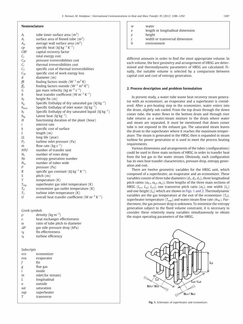
There are twelve geometric variables for the HRSG unit, whichcomposed of a superheater, an evaporator and an economizer. Thesevariables consist of three tube diameters (d1, d2, d3), three longitudinalpitch ratios (αL1, αL2, αL3), three lengths of the three main sections ofHRSG (Lx1, Lx2, Lx3), one transverse pitch ratio (αz), one width (Lz)and one height (Ly) which are shown in Figs. 1 and 2. Thermodynamicvariables are the gas temperature at the exit of the economizer (Td),superheater temperature (Tsup) and water/steam flow rate _mWð Þ. Fur-thermore, the gas pressure drop is unknown. Tominimize the entropygeneration subject to the fixed volume constraint, it is necessary toconsider these relatively many variables simultaneously to obtainthe major operating parameters of the HRSG.
Fig. 1. Schematic of superheater and economizer.
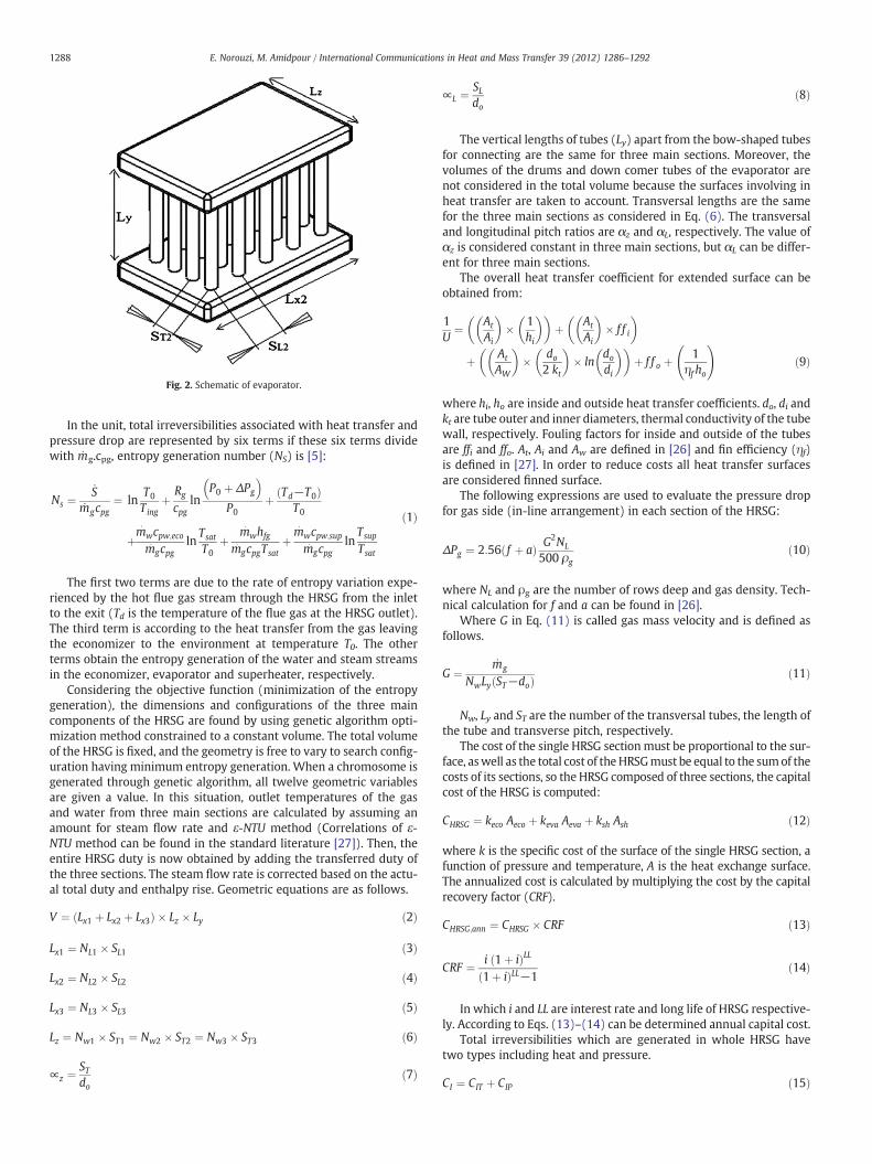
Fig. 2. Schematic of evaporator.
1288 E. Norouzi, M. Amidpour / International Communications in Heat and Mass Transfer 39 (2012) 1286–1292
In the unit, total irreversibilities associated with heat transfer andpressure drop are represented by six terms if these six terms dividewith _mg.cpg, entropy generation number (NS) is [5]:
Ns ¼_S
_mgcpg¼ ln
T0
Tingþ Rg
cpgln
P0 þ ΔPg
� �P0
þ Td−T0ð ÞT0
þm�wcpw;eco
m� gcpgln
Tsat
T0þ m� whfgm� gcpgTsat
þm� wcpw;sup
m� gcpgln
Tsup
Tsat
ð1Þ
The first two terms are due to the rate of entropy variation expe-rienced by the hot flue gas stream through the HRSG from the inletto the exit (Td is the temperature of the flue gas at the HRSG outlet).The third term is according to the heat transfer from the gas leavingthe economizer to the environment at temperature T0. The otherterms obtain the entropy generation of the water and steam streamsin the economizer, evaporator and superheater, respectively.
Considering the objective function (minimization of the entropygeneration), the dimensions and configurations of the three maincomponents of the HRSG are found by using genetic algorithm opti-mization method constrained to a constant volume. The total volumeof the HRSG is fixed, and the geometry is free to vary to search config-uration having minimum entropy generation. When a chromosome isgenerated through genetic algorithm, all twelve geometric variablesare given a value. In this situation, outlet temperatures of the gasand water from three main sections are calculated by assuming anamount for steam flow rate and ε-NTU method (Correlations of ε-NTU method can be found in the standard literature [27]). Then, theentire HRSG duty is now obtained by adding the transferred duty ofthe three sections. The steam flow rate is corrected based on the actu-al total duty and enthalpy rise. Geometric equations are as follows.
V ¼ Lx1 þ Lx2 þ Lx3ð Þ � Lz � Ly ð2Þ
Lx1 ¼ NL1 � SL1 ð3Þ
Lx2 ¼ NL2 � SL2 ð4Þ
Lx3 ¼ NL3 � SL3 ð5Þ
Lz ¼ Nw1 � ST1 ¼ Nw2 � ST2 ¼ Nw3 � ST3 ð6Þ
∝z ¼STdo
ð7Þ
∝L ¼SLdo
ð8Þ
The vertical lengths of tubes (Ly) apart from the bow-shaped tubesfor connecting are the same for three main sections. Moreover, thevolumes of the drums and down comer tubes of the evaporator arenot considered in the total volume because the surfaces involving inheat transfer are taken to account. Transversal lengths are the samefor the three main sections as considered in Eq. (6). The transversaland longitudinal pitch ratios are αz and αL, respectively. The value ofαz is considered constant in three main sections, but αL can be differ-ent for three main sections.
The overall heat transfer coefficient for extended surface can beobtained from:
1U
¼ At
Ai
� �� 1
hi
� �� �þ At
Ai
� �� f f i
� �
þ At
AW
� �� do
2 kt
� �� ln
dodi
� �� �þ f f o þ
1ηf ho
!ð9Þ
where hi, ho are inside and outside heat transfer coefficients. do, di andkt are tube outer and inner diameters, thermal conductivity of the tubewall, respectively. Fouling factors for inside and outside of the tubesare ffi and ffo. At, Ai and Aw are defined in [26] and fin efficiency (ηf)is defined in [27]. In order to reduce costs all heat transfer surfacesare considered finned surface.
The following expressions are used to evaluate the pressure dropfor gas side (in-line arrangement) in each section of the HRSG:
ΔPg ¼ 2:56 f þ að Þ G2NL
500 ρgð10Þ
where NL and ρg are the number of rows deep and gas density. Tech-nical calculation for f and a can be found in [26].
Where G in Eq. (11) is called gas mass velocity and is defined asfollows.
G ¼_mg
NwLy ST−doð Þ ð11Þ
Nw, Ly and ST are the number of the transversal tubes, the length ofthe tube and transverse pitch, respectively.
The cost of the single HRSG sectionmust be proportional to the sur-face, aswell as the total cost of theHRSGmust be equal to the sumof thecosts of its sections, so the HRSG composed of three sections, the capitalcost of the HRSG is computed:
CHRSG ¼ keco Aeco þ keva Aeva þ ksh Ash ð12Þ
where k is the specific cost of the surface of the single HRSG section, afunction of pressure and temperature, A is the heat exchange surface.The annualized cost is calculated by multiplying the cost by the capitalrecovery factor (CRF).
CHRSG;ann ¼ CHRSG � CRF ð13Þ
CRF ¼ i 1þ ið ÞLL1þ ið ÞLL−1
ð14Þ
In which i and LL are interest rate and long life of HRSG respective-ly. According to Eqs. (13)–(14) can be determined annual capital cost.
Total irreversibilities which are generated in whole HRSG havetwo types including heat and pressure.
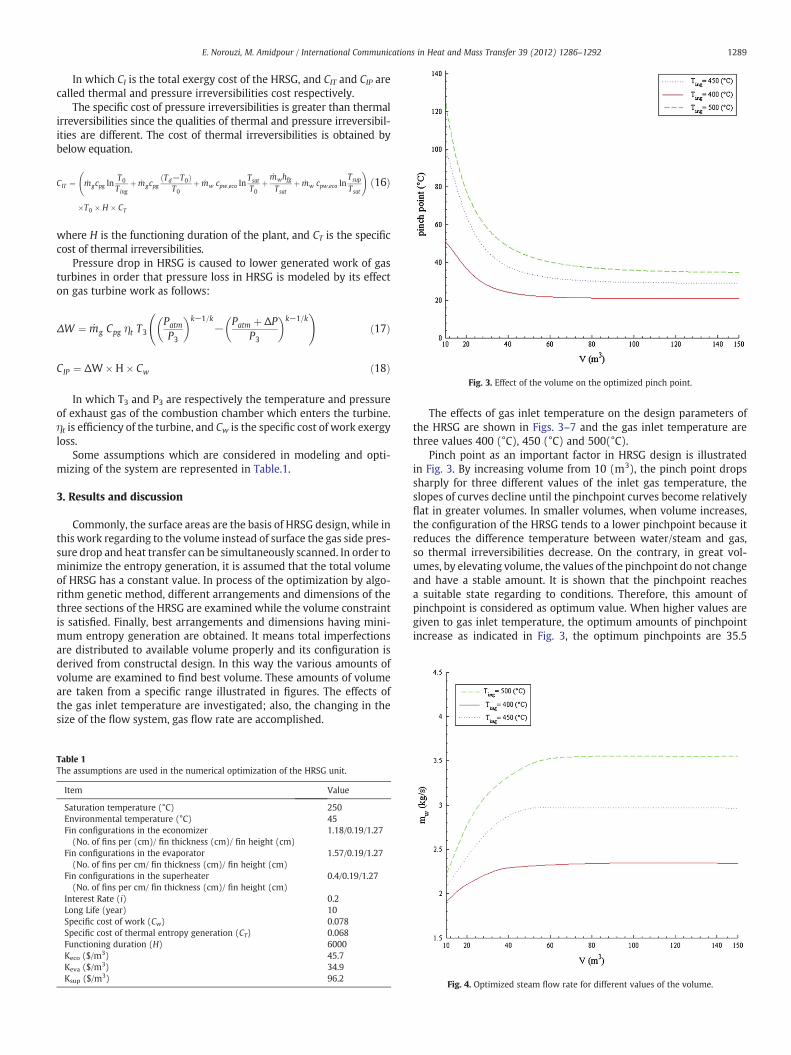
Fig. 3. Effect of the volume on the optimized pinch point.
1289E. Norouzi, M. Amidpour / International Communications in Heat and Mass Transfer 39 (2012) 1286–1292
In which CI is the total exergy cost of the HRSG, and CIT and CIP arecalled thermal and pressure irreversibilities cost respectively.
The specific cost of pressure irreversibilities is greater than thermalirreversibilities since the qualities of thermal and pressure irreversibil-ities are different. The cost of thermal irreversibilities is obtained bybelow equation.
CIT ¼ _mgcpg lnT0
Tingþ _mgcpg
Td−T0ð ÞT0
þ _mw cpw;eco lnTsat
T0þ
_mwhfgTsat
þ _mw cpw;eco lnTsup
Tsat
!
�T0 � H � CT
ð16Þ
where H is the functioning duration of the plant, and CT is the specificcost of thermal irreversibilities.
Pressure drop in HRSG is caused to lower generated work of gasturbines in order that pressure loss in HRSG is modeled by its effecton gas turbine work as follows:
ΔW ¼ _mg Cpg ηt T3Patm
P3
� �k−1=k− Patm þ ΔP
P3
� �k−1=k !
ð17Þ
CIP ¼ ΔW�H� Cw ð18Þ
In which T3 and P3 are respectively the temperature and pressureof exhaust gas of the combustion chamber which enters the turbine.ηt is efficiency of the turbine, and Cw is the specific cost of work exergyloss.
Some assumptions which are considered in modeling and opti-mizing of the system are represented in Table.1.
3. Results and discussion
Commonly, the surface areas are the basis of HRSG design, while inthis work regarding to the volume instead of surface the gas side pres-sure drop and heat transfer can be simultaneously scanned. In order tominimize the entropy generation, it is assumed that the total volumeof HRSG has a constant value. In process of the optimization by algo-rithm genetic method, different arrangements and dimensions of thethree sections of the HRSG are examined while the volume constraintis satisfied. Finally, best arrangements and dimensions having mini-mum entropy generation are obtained. It means total imperfectionsare distributed to available volume properly and its configuration isderived from constructal design. In this way the various amounts ofvolume are examined to find best volume. These amounts of volumeare taken from a specific range illustrated in figures. The effects ofthe gas inlet temperature are investigated; also, the changing in thesize of the flow system, gas flow rate are accomplished.
Table 1The assumptions are used in the numerical optimization of the HRSG unit.
Item Value
Saturation temperature (°C) 250Environmental temperature (°C) 45Fin configurations in the economizer(No. of fins per (cm)/ fin thickness (cm)/ fin height (cm)
1.18/0.19/1.27
Fin configurations in the evaporator(No. of fins per cm/ fin thickness (cm)/ fin height (cm)
1.57/0.19/1.27
Fin configurations in the superheater(No. of fins per cm/ fin thickness (cm)/ fin height (cm)
0.4/0.19/1.27
Interest Rate (i) 0.2Long Life (year) 10Specific cost of work (Cw) 0.078Specific cost of thermal entropy generation (CT) 0.068Functioning duration (H) 6000Keco ($/m3) 45.7Keva ($/m3) 34.9Ksup ($/m3) 96.2
The effects of gas inlet temperature on the design parameters ofthe HRSG are shown in Figs. 3–7 and the gas inlet temperature arethree values 400 (°C), 450 (°C) and 500(°C).
Pinch point as an important factor in HRSG design is illustratedin Fig. 3. By increasing volume from 10 (m3), the pinch point dropssharply for three different values of the inlet gas temperature, theslopes of curves decline until the pinchpoint curves become relativelyflat in greater volumes. In smaller volumes, when volume increases,the configuration of the HRSG tends to a lower pinchpoint because itreduces the difference temperature between water/steam and gas,so thermal irreversibilities decrease. On the contrary, in great vol-umes, by elevating volume, the values of the pinchpoint do not changeand have a stable amount. It is shown that the pinchpoint reachesa suitable state regarding to conditions. Therefore, this amount ofpinchpoint is considered as optimum value. When higher values aregiven to gas inlet temperature, the optimum amounts of pinchpointincrease as indicated in Fig. 3, the optimum pinchpoints are 35.5
Fig. 4. Optimized steam flow rate for different values of the volume.
Fig. 7. Optimized entropy generation number values by varying volume.Fig. 5. Effect of the volume on the optimized superheater temperature.
1290 E. Norouzi, M. Amidpour / International Communications in Heat and Mass Transfer 39 (2012) 1286–1292
(°C), 30 (°C) and 21 (°C) for gas inlet temperatures 500 (°C), 450 (°C)and 400 (°C) respectively. In addition, by increasing gas inlet temper-ature, the curves of pinchpoint-V in greater volumes reach a relativelyflat region.
Regarding Fig. 4 the amounts of water/steam flow rate _mwð Þ risesharply at the beginning but in greater volumes, the slopes of curvesdecline until become flat. Totally, decreasing water flow rate leads toreduce fourth, fifth and sixth term of the entropy generation. But, forbalancing energy, Tsup or Td increases. In these cases, last or third termof the entropy generation grows. Therefore, there is an optimumamount for _mw. When entropy generation is minimized By increasingTing, it is obvious to get a greater stable amount and it is realized in agreater volume.
Fig. 5 shows the amounts of superheater temperature for volumes10 (m3) to 150 (m3). In entropy generation function Eq. (1), if Tsupdecreases, the last term of Eq. (1) will have a lower value. In thiscase, _mW or Td increase in order to balance energy and they leads toincrease the last four terms of Eq. (1). Thus, there is an optimum
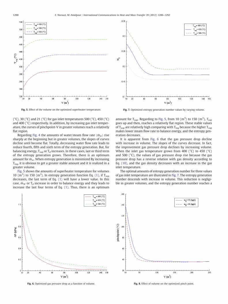
Fig. 6. Optimized gas pressure drop as a function of volume.
amount for Tsup. Regarding to Fig. 5, from 10 (m3) to 150 (m3), Tsupgoes up and then, reaches a relatively flat region. These stable valuesof Tsup are relatively high comparing with Ting because the higher Tsupmakes lower steam flow rate to balance energy, and the entropy gen-eration decreases.
It is apparent from Fig. 6 that the gas pressure drop declinewith increase in volume. The slopes of the curves decrease. In fact,the improvement gas pressure drop declines by increasing volume.When the inlet gas temperature grows from 400 (°C) to 450 (°C)and 500 (°C), the values of gas pressure drop rise because the gaspressure drop has a reverse relation with gas density according toEq. (10), and the gas density decreases with an increase in the gasinlet temperature.
The optimal amounts of entropy generation number for three valuesof gas inlet temperature are illustrated in Fig. 7. The entropy generationnumber descends with increase in volume. This reduction is negligi-ble in greater volumes, and the entropy generation number reaches a
Fig. 8. Effect of volume on the optimized pinch point.
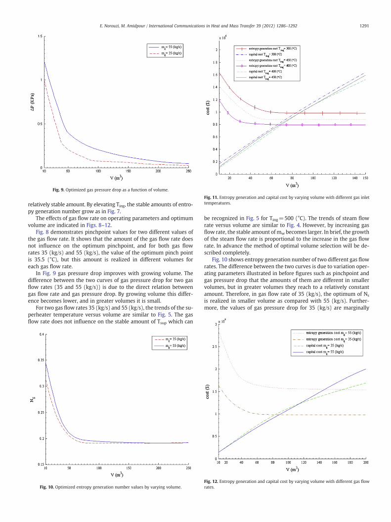
Fig. 11. Entropy generation and capital cost by varying volume with different gas inlettemperatures.
Fig. 9. Optimized gas pressure drop as a function of volume.
1291E. Norouzi, M. Amidpour / International Communications in Heat and Mass Transfer 39 (2012) 1286–1292
relatively stable amount. By elevating Ting, the stable amounts of entro-py generation number grow as in Fig. 7.
The effects of gas flow rate on operating parameters and optimumvolume are indicated in Figs. 8–12.
Fig. 8 demonstrates pinchpoint values for two different values ofthe gas flow rate. It shows that the amount of the gas flow rate doesnot influence on the optimum pinchpoint, and for both gas flowrates 35 (kg/s) and 55 (kg/s), the value of the optimum pinch pointis 35.5 (°C), but this amount is realized in different volumes foreach gas flow rate.
In Fig. 9 gas pressure drop improves with growing volume. Thedifference between the two curves of gas pressure drop for two gasflow rates (35 and 55 (kg/s)) is due to the direct relation betweengas flow rate and gas pressure drop. By growing volume this differ-ence becomes lower, and in greater volumes it is small.
For two gas flow rates 35 (kg/s) and 55 (kg/s), the trends of the su-perheater temperature versus volume are similar to Fig. 5. The gasflow rate does not influence on the stable amount of Tsup which can
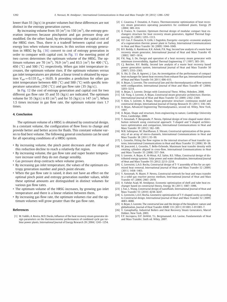
Fig. 10. Optimized entropy generation number values by varying volume.
be recognized in Fig. 5 for Ting=500 (°C). The trends of steam flowrate versus volume are similar to Fig. 4. However, by increasing gasflow rate, the stable amount ofmw becomes larger. In brief, the growthof the steam flow rate is proportional to the increase in the gas flowrate. In advance the method of optimal volume selection will be de-scribed completely.
Fig. 10 shows entropy generation number of two different gas flowrates. The difference between the two curves is due to variation oper-ating parameters illustrated in before figures such as pinchpoint andgas pressure drop that the amounts of them are different in smallervolumes, but in greater volumes they reach to a relatively constantamount. Therefore, in gas flow rate of 35 (kg/s), the optimum of Ns
is realized in smaller volume as compared with 55 (kg/s). Further-more, the values of gas pressure drop for 35 (kg/s) are marginally
Fig. 12. Entropy generation and capital cost by varying volume with different gas flowrates.
1292 E. Norouzi, M. Amidpour / International Communications in Heat and Mass Transfer 39 (2012) 1286–1292
lower than 55 (kg/s) in greater volumes but these differences are notdistinct in the entropy generation curves.
By increasing volume from 10 (m3) to 150 (m3), the entropy gen-eration improves because pinchpoint and gas pressure drop aremodified. On the other hand, by elevating volume the capital cost ofthe HRSG rises. Thus, there is a tradeoff between capital cost andexergy loss when volume increases. In this section entropy genera-tion in HRSG by Eq. (16) convert to cost of entropy generation inorder to compare with capital cost. In Fig. 11 the meeting point oftwo curves determines the optimum volume of the HRSG. The op-timum volumes are 70 (m3), 76.9 (m3) and 83.5 (m3) for 400 (°C),450 (°C) and 500 (°C) respectively. When gas inlet temperature in-creases, the optimum volume rises. If the optimum volumes versusgas inlet temperatures are plotted, a linear trend is obtained by equa-tion Vopt=0.135 Ting+16.05. It provides a prediction for other gasinlet temperature between 400 (°C) and 500 (°C) with specific tem-perature saturation (250 (°C)) and gas flow rate (35 (kg/s)).
In Fig. 12 the cost of entropy generation and capital cost for twodifferent gas flow rate 35 and 55 (kg/s) are indicated. The optimumvolume for 35 (kg/s) is 83 (m3) and for 55 (kg/s) is 147 (m3). When1.5 times increase in gas flow rate, the optimum volume rises 1.7times.
4. Conclusion
The optimum volume of a HRSG is obtained by constructal design.In a constant volume, the configuration of flow frees to change andprovide better and better access for fluids. This constant volume var-ies to find best volume. The following general conclusions can be usedfor all operating conditions of a HRSG system.
• By increasing volume, the pinch point decreases and the slope ofthis reduction decline to reach a relatively flat region.
• By increasing volume, the gas flow rate and super heater tempera-ture increase until they do not change sensibly.
• Gas pressure drop contracts when volume grows.• By increasing gas inlet temperature, the values of the optimum en-tropy generation number and pinch point elevate.
• When the gas flow rate is raised, it does not have an effect on theoptimal pinch point and entropy generation number values, whilethese optimal amounts are distinguished in distinct volumes forvarious gas flow rates.
• The optimum volume of the HRSG increases, by growing gas inlettemperature and there is a linear relation between them.
• By increasing gas flow rate, the optimum volumes rise and the op-timum volumes will grow greater than the gas flow rate.
References
[1] M. Valdés, A. Rovira, M.D. Durán, Influence of the heat recovery steam generator de-sign parameters on the thermoeconomic performances of combined cycle gas tur-bine power plants, International Journal of Energy Research 28 (2004) 1243–1254.
[2] C. Casarosa, F. Donatini, A. Franco, Thermoeconomic optimization of heat recov-ery steam generators operating parameters for combined plants, Energy 29(2004) 389–414.
[3] A. Franco, N. Giannini, Optimum thermal design of modular compact heat ex-changers structure for heat recovery steam generators, Applied Thermal Engi-neering 25 (2005) 1293–1313.
[4] O.F. Can, F. Donatini, N. Celik, I. Dagtekin, Energetic–exergetic–economic analysesof a cogeneration thermic power plant in Turkey, International Communicationsin Heat and Mass Transfer 36 (2009) 1044–1049.
[5] B.V. Reddy, G. Ramkiran, K.K. Ashok, P.K. Nag, Second law analysis of a waste heatrecovery steam generator, International Journal of Heat and Mass Transfer 45(2002) 1807–1814.
[6] P.K. Nag, S. De, Design and operation of a heat recovery steam generator withminimum irreversibility, Applied Thermal Engineering 17 (1997) 385–391.
[7] C.J. Butcher, B.V. Reddy, Second law analysis of a waste heat recovery basedpower generation system, International Journal of Heat and Mass Transfer 50(2007) 2355–2363.
[8] X. Shi, D. Che, B. Agnewi, J. Gao, An investigation of the performance of compactheat exchanger for latent heat recovery from exhaust flue gas, International Journalof Heat and Mass Transfer 54 (2011) 606–615.
[9] A. Bejan, S. Lorente, The constructal law and the thermodynamics of flow systemswith configuration, International Journal of Heat and Mass Transfer 47 (2004)3203–3214.
[10] A. Bejan, S. Lorente, Design with Constructal Theor, Wiley, Hoboken, 2008.[11] S.K. Yong, S. Lorente, A. Bejan, Constructal steam generator architecture, Elsevier,
International Journal of Heat and Mass Transfer 52 (2009) 2362–2369.[12] Y. Kim, S. Lorente, A. Bejan, Steam generator structure: continuous model and
constructal design, International Journal of Energy Research 35 (2011) 336–345.[13] A. Bejan, Advanced Engineering Thermodynamics, second ed. Wiley, New York,
1997.[14] A. Bejan, Shape and structure, from engineering to nature, Cambridge University
Press, Cambridge, 2000.[15] Y. Azoumah, P. Bieupoude, P. Neveu, Optimal design of tree-shaped water distri-
bution network using constructal approach: T-shaped and Y-shaped architec-tures optimization and comparison, International Communications in Heat andMass Transfer 39 (2012) 182–189.
[16] M.R. Salimpour, M. Sharifhasan, E. Shirani, Constructal optimization of the geom-etry of an array of micro-channels, International Communications in Heat andMass Transfer 38 (2011) 93–99.
[17] L. Gosselin, Fitting the flow regime in the internal structure of heat transfer sys-tems, International Communications in Heat and Mass Transfer 33 (2006) 30–38.
[18] M. Joucaviel, L. Gosselin, T. Bello-Ochende, Maximum heat transfer density withrotating cylinders aligned in cross-flow, International Communications in Heatand Mass Transfer 35 (2008) 557–564.
[19] S. Lorente, A. Bejan, K. Al-Hinai, A.Z. Sahin, B.S. Yilbas, Constructal design of dis-tributed energy systems: Solar power and water desalination, International Journalof Heat and Mass Transfer 55 (2012) 2213–2218.
[20] G. Lorenzini, L.A.O. Rocha, Constructal design of T–Y assembly of fins for an opti-mized heat removal, International Journal of Heat and Mass Transfer 52 (2009)(2011) 1458–1463.
[21] Y. Azoumah, N. Mazet, P. Neveu, Constructal network for heat and mass transferin a solid–gas reactive porous medium, International Journal of Heat and MassTransfer 47 (2004) 2961–2970.
[22] A. Vahdat Azad, M. Amidpour, Economic optimization of shell and tube heat ex-changer based on constructal theory, Energy 36 (2011) 1087–1096.
[23] J. Fan, L. Wang, Constructal design of nanofluids, International Journal of Heat andMass Transfer 53 (2010) 4238–4247.
[24] G. Lorenzini, L.A.O. Rocha, Geometric optimization of T-Y-shaped cavity accordingto Constructal design, International Journal of Heat and Mass Transfer 52 (2009)4683–4688.
[25] A. Bejan, S. Lorente, The constructal law and the design of the biosphere: nature andglobalization, Journal of Heat Transfer ASME 133 (2011) 011001-1-011001-7.
[26] V. Ganaphathy, Industrial Boilers and Heat Recovery Steam Generators, MarcelDekker, New York, 2003.
[27] F.P. Incropera, D.P. DeWitt, T.L. Bergmanand, A.S. Lavine, Fundamentals of Heatand Mass Transfer, Sixth ed. Wiley, 2007.