Indian Geotechnical Conference 2017 GeoNEst 14-16 December 2017, IIT Guwahati, India 1 Optimisation of Base Width of a Typical Concrete Gravity Dam under Different Seismic Conditions using Static Seismic Loading Sukanya Talukdar Prasanna Kumar Khaund Department of Civil Engineering, Jorhat Engineering College, Jorhat - 785007 E-mail: [email protected]; [email protected]ABSTRACT: A concrete gravity dam is a major hydraulic structure and it is very essential to consider the earthquake forces, to get a proper design base width, so that the entire weight of the dam resists the overturning moment due to earthquake and other forces. The main objective of this study is to obtain the design base width of a dam for different seismic conditions by varying the earthquake coefficients in both vertical and horizontal directions. This shall be done by equating the different factors of safety for a dam with their limiting conditions under both tail water and no tail water condition. The shape of the Mettur dam in India is considered for the study. The study has been done taking a constant head of water at the reservoir, which is the maximum reservoir water level and a constant height of tail water. Using linear approximation method of Newton Raphson, the obtained equations against different factors of safety under different earthquake conditions are solved using a programme in C++ to get different values of base width of dam for varying earthquake conditions. Keywords: Design Base Width, Horizontal Earthquake Coefficient, Tail Water, Vertical Earthquake Coefficient. 1. Introduction A dam is a major hydraulic structure which restricts the flow of water or underground streams thereby creating reservoirs. The water stored by reservoirs can be used for different purposes like irrigation, human consumption, hydropower, industrial use, aquaculture and navigability. The retained water from the dam can also be evenly distributed between locations. A concrete gravity dam is a structure whose own weight resists the external forces like water pressure, uplift pressure, pressure due to earthquake forces, silt pressure, ice pressure, wind pressure and wave pressure etc. It is the most durable and requires very little maintenance. The resisting moment of a dam makes it stable. By the end of the 20th century it was seen that over 45,000 large dams were built in 150 countries as per the data base from International Commission on Large Dams - ICOLD (Mohan and Ramancharla, 2013). In India nearly 3200 major and minor dams and barrages had been constructed by the year 2012. Maharashtra has the largest number of dams in India which was reported to be 1676 numbers in the year 2009, followed by Madhya Pradesh having as many as 899 numbers of major/minor dams during the same year. Gujarat, Andhra Pradesh, Chhattisgarh, Karnataka, Rajasthan, Orissa, Uttar Pradesh, Uttarakhand and Tamil Nadu are some of the states with the largest numbers of dams in the country. The Subansiri Lower Dam, on the Subansiri River in North Eastern India is a concrete gravity dam undergoing construction and if it is completed as planned, it will be the largest hydroelectric project in India supplying 2000 MW of hydroelectricity. Consideration of earthquake forces is a major concern for the construction of major structures like dams. Based on the severity of earthquake, entire India is divided into four seismic zones using IS-1893 (Part 1), 2002. For the purpose of simplification of the analysis, the forces due to wind pressure, ice pressure, silt pressure and wave pressure are not taken into consideration. Fenves et al (1987) did a comparison of the seismic analysis of a concrete gravity dam using EAGD-84 to one that was obtained using traditional method. The analysis comprised of a two stage procedure in which the preliminary design and safety evaluation was done using the fundamental vibration obtained from the earthquake design spectrum. The second step included the idealization of the dam monolith using refined response history analysis procedure that was used to compute the dynamic response of the structure and to check the accuracy of the values so obtained from the preliminary evaluation. The analysis was done for Pine Flat Dam over Kings River in United States. Four cases of the dam were studied for both rigid and flexible foundation with reservoir full and empty condition and fundamental mode properties were evaluated and stresses evaluated and were compared in both upstream and downstream face for both simplified and refined procedure. Ali et al (2012), did a comparison in the design and analysis of concrete gravity dam by using ANSYS where vertical, principal and shear stresses were obtained, with the one done by 2D gravity method and earthquake forces were taken within the range of 0.1g-0.3g. It was seen that using 2D gravity method, the volume of concrete required per meter length of the dam, increased exponentially to make the dam safe for horizontal earthquake pressure, while other loads were not varied. It was found that the principal stresses at the toe of the dam using FEM analyses for 0.10g - 0.15g could be made safer by flattening the upstream face of the dam. However it was not possible to make it safe in the case of 2D gravity method for horizontal earthquake intensity of 0.3g and greater. Moreover, it was very difficult to achieve the required factor of safety against sliding, especially for 0.3g horizontal earthquake intensity. From the study it was concluded that it would not be feasible to construct a concrete gravity dam for horizontal earthquake acceleration values greater than 0.3g without changing other loads or dimension of the dam for the particular site conditions.
Transcript
Indian Geotechnical Conference 2017 GeoNEst14-16 December 2017, IIT Guwahati, India
1
Optimisation of Base Width of a Typical Concrete Gravity Dam under Different Seismic Conditions using Static Seismic Loading
Sukanya Talukdar Prasanna Kumar Khaund Department of Civil Engineering, Jorhat Engineering College, Jorhat - 785007 E-mail: [email protected]; [email protected]
ABSTRACT: A concrete gravity dam is a major hydraulic structure and it is very essential to consider the earthquake forces, to get a proper design base width, so that the entire weight of the dam resists the overturning moment due to earthquake and other forces. The main objective of this study is to obtain the design base width of a dam for different seismic conditions by varying the earthquake coefficients in both vertical and horizontal directions. This shall be done by equating the different factors of safety for a dam with their limiting conditions under both tail water and no tail water condition. The shape of the Mettur dam in India is considered for the study. The study has been done taking a constant head of water at the reservoir, which is the maximum reservoir water level and a constant height of tail water. Using linear approximation method of Newton Raphson, the obtained equations against different factors of safety under different earthquake conditions are solved using a programme in C++ to get different values of base width of dam for varying earthquake conditions.
1. Introduction A dam is a major hydraulic structure which restricts the flow of water or underground streams thereby creating reservoirs. The water stored by reservoirs can be used for different purposes like irrigation, human consumption, hydropower, industrial use, aquaculture and navigability. The retained water from the dam can also be evenly distributed between locations. A concrete gravity dam is a structure whose own weight resists the external forces like water pressure, uplift pressure, pressure due to earthquake forces, silt pressure, ice pressure, wind pressure and wave pressure etc. It is the most durable and requires very little maintenance. The resisting moment of a dam makes it stable.
By the end of the 20th century it was seen that over 45,000 large dams were built in 150 countries as per the data base from International Commission on Large Dams - ICOLD (Mohan and Ramancharla, 2013). In India nearly 3200 major and minor dams and barrages had been constructed by the year 2012. Maharashtra has the largest number of dams in India which was reported to be 1676 numbers in the year 2009, followed by Madhya Pradesh having as many as 899 numbers of major/minor dams during the same year. Gujarat, Andhra Pradesh, Chhattisgarh, Karnataka, Rajasthan, Orissa, Uttar Pradesh, Uttarakhand and Tamil Nadu are some of the states with the largest numbers of dams in the country. The Subansiri Lower Dam, on the Subansiri River in North Eastern India is a concrete gravity dam undergoing construction and if it is completed as planned, it will be the largest hydroelectric project in India supplying 2000 MW of hydroelectricity.
Consideration of earthquake forces is a major concern for the construction of major structures like dams. Based on the severity of earthquake, entire India is divided into four seismic zones using IS-1893 (Part 1), 2002. For the purpose of simplification of the analysis, the forces due to wind pressure, ice pressure, silt pressure and wave pressure are not taken into consideration.
Fenves et al (1987) did a comparison of the seismic analysis of a concrete gravity dam using EAGD-84 to one that was obtained using traditional method. The analysis comprised of a two stage procedure in which the preliminary design and safety evaluation was done using the fundamental vibration obtained from the earthquake design spectrum. The second step included the idealization of the dam monolith using refined response history analysis procedure that was used to compute the dynamic response of the structure and to check the accuracy of the values so obtained from the preliminary evaluation. The analysis was done for Pine Flat Dam over Kings River in United States. Four cases of the dam were studied for both rigid and flexible foundation with reservoir full and empty condition and fundamental mode properties were evaluated and stresses evaluated and were compared in both upstream and downstream face for both simplified and refined procedure.
Ali et al (2012), did a comparison in the design and analysis of concrete gravity dam by using ANSYS where vertical, principal and shear stresses were obtained, with the one done by 2D gravity method and earthquake forces were taken within the range of 0.1g-0.3g. It was seen that using 2D gravity method, the volume of concrete required per meter length of the dam, increased exponentially to make the dam safe for horizontal earthquake pressure, while other loads were not varied. It was found that the principal stresses at the toe of the dam using FEM analyses for 0.10g - 0.15g could be made safer by flattening the upstream face of the dam. However it was not possible to make it safe in the case of 2D gravity method for horizontal earthquake intensity of 0.3g and greater. Moreover, it was very difficult to achieve the required factor of safety against sliding, especially for 0.3g horizontal earthquake intensity. From the study it was concluded that it would not be feasible to construct a concrete gravity dam for horizontal earthquake acceleration values greater than 0.3g without changing other loads or dimension of the dam for the particular site conditions.
Optimisation of Base Width of a Typical Concrete Gravity Dam under Different Seismic Conditions using Static Seismic Loading
2
Verma et al (2012) studied the Hirakud Dam, which is a composite dam made of concrete and masonry and did a dynamic earthquake analysis using CADAM, during strong ground acceleration caused by earthquake. The design of the dam was checked for the PGA of an earlier earthquake which was taken to be 0.16g. The Hirakud dam was checked whether any up gradation was necessary from seismic point of view.
Arun and Raghuraman (2016) made a study on the response of gravity dam under different earthquake accelerations using ANSYS on the Koyna Dam in Maharashtra, India. The dam was checked for a varying earthquake conditions and was seen to fail due to tension when an earthquake force of 0.5g was applied. Hence the upstream face was remodeled by varying the angle of the upstream slope which increased the base width and the result of the new model was analysed using ANSYS.
2. Dam Model The shape of the model of the dam is considered for this study is of Mettur dam. Mettur dam is one of the oldest concrete gravity dam situated over the Kaveri River in Salem district of Tamil Nadu, India. Figure 1 represents the model of the dam. In the present analysis the variation of base width of the dam with respect to the variation of seismic coefficients are observed for a given height of a dam and particular tail water level. Although this study has been done for the Mettur dam, it can be applied for any gravity dam at different sites by changing the height of the dam, uplift parameters and earthquake coefficients for a given site condition.
Fig. 1 Model of dam
3. Methodology The constant height of dam considered for the analysis is 50.0m with a freeboard of 4.0m and a tail water of 10.0m. A coefficient of friction of 0.75 and shear strength of concrete of 1400N/mm2 is chosen from the user, although these may vary as per convenience. An uplift coefficient is arbitrarily taken as 2/3. The base of the dam is divided into three sections in proportion to B. The forces considered are the weight of the dam, water pressure, uplift of water, hydrodynamic pressure and earthquake pressure. According to Zangler, total hydrodynamic pressure, for a reservoir of height H is given by,
0.726 (1)
where the hydrodynamic force, pey, is given as,
(2)
0.735 /90° (3)
Where,
Ө Inclination of upstream face with horizontal,
γw Unit weight of Water and
αh = Horizontal earthquake acceleration. The moment of this force above base is
0.412 (4)
The net vertical and horizontal forces are calculated and hence the resisting moments, MR, and the total overturning moments, MO, are computed. Equating the factor of safety against overturning = 1.5, sliding = 1, shear friction factor = 4, and accepting the values of αv and αh from the user, equations are obtained in terms of the variable B, i.e. the base width of the dam. These equations are solved by Newton Raphson method in C++ to arrive at a particular value of base width, B. Earthquake coefficients within the range of αh = 0.0-0.10g and αv = 0.0-0.10g are chosen with an increment of 0.01g.
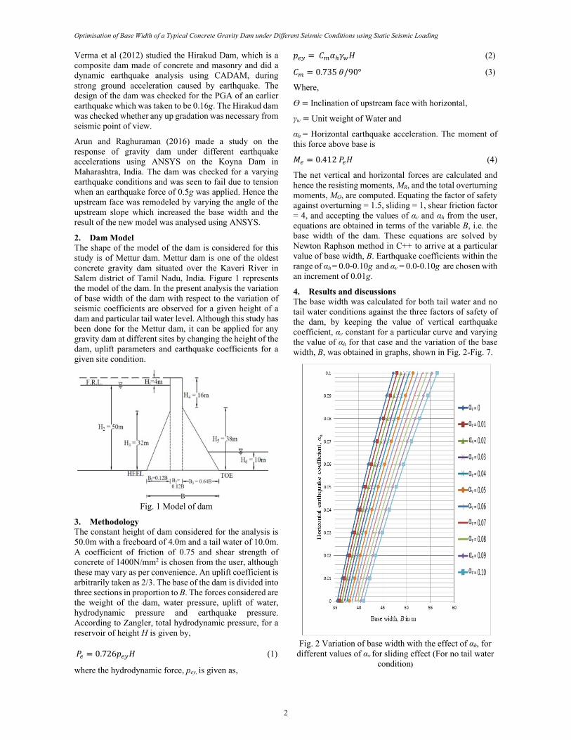
4. Results and discussions The base width was calculated for both tail water and no tail water conditions against the three factors of safety of the dam, by keeping the value of vertical earthquake coefficient, αv constant for a particular curve and varying the value of αh for that case and the variation of the base width, B, was obtained in graphs, shown in Fig. 2-Fig. 7.
Fig. 2 Variation of base width with the effect of αh, for
different values of αv for sliding effect (For no tail water condition)
Indian Geotechnical Conference 2017 - GeoNEst 14-16 December 2017, IIT Guwahati, India
3
Fig. 3 Variation of base width with the effect of αh, for different values of αv for overturning (For no tail water
condition)
Fig. 4 Variation of base width with the effect of αh, for
different values of αv for safety against shear friction (For no tail water condition)
Fig. 5 Variation of base width with the effect of αh, for different values of αv for sliding effect (For tail water
condition)
Fig. 6 Variation of base width with the effect of αh, for
different values of v for overturning (For tail water condition)
Optimisation of Base Width of a Typical Concrete Gravity Dam under Different Seismic Conditions using Static Seismic Loading
4
Fig. 7 Variation of base width with the effect of αh, for different values of v for shear friction (For tail water
condition)
The above results signify that there is an increase in the base width with the variation of earthquake coefficients. The graphs show a distinct variation of base width for the dam when the earthquake acceleration parameters are varied for αv = 0-0.1g and αh = 0-0.1g. Variation of base width for no tail water condition is represented in Fig. 2-Fig. 4, for factor of safety against sliding, overturning and shear friction, while the variation in base width for tail water condition is plotted in Fig. 5-Fig. 7. For smaller values of αh the variation in base width between two consecutive curves is less than when αh increases. Thus the variation increases as the earthquake coefficient, αh, increases. Again it is seen that the value of B, is more in case of reservoir with tail water than in the no tail water condition because of the presence of uplift pressure in the tail water condition whose effect is more dominating, that it increases the overturning moment. Only in the case of factor of safety for shear friction factor such a trend is not followed due to the effect of shear strength of concrete which is kept as a constant value. Also the variation in base width is seen to be least in case of the base width calculated for factor of safety against shear friction.
5. Conclusions The study concludes the trend of variation of base width of a concrete gravity dam for a given full reservoir level, keeping free board and top width as constant parameters. The study has been made for two different tail water conditions, with a given tail water depth and also for no tail water condition under different static earthquake
loading conditions. As earthquake load increases the base width also increases. It may be observed that the value of base width, B, is nearly linear upto αh = 0.05 after which the variation in the curve increases on increasing the value of αh. Amongst all the three factor of safety considered, the limiting value for factor of safety for shear friction is least, while it is maximum for factor of safety for sliding only when the αv and αh are less. The base width gradually increases and becomes maximum in case of factor of safety for overturning as αv and αh increases to 0.1g. For the design purpose, maximum value of base width for a particular earthquake and tail water condition is to be considered. The trend of variation of base width is seen to be similar in case of both the tail water conditions.
Although this study has been done for the Mettur dam, it can be applied for any gravity dam at different sites by changing the height of the dam, uplift parameters and earthquake coefficients applicable for a given site condition.
References
Ali, M.H., Alam M.R., Haque M.N.and Alam, M.H. (2012) Comparison of Design and Analysis of Concrete Gravity Dam, Natural Resources, 3(1), pp. 18-28, http://dx.doi.org/10.4236/nr.2012.31004.
Arun, K.S. and Raghuraman, S. (2016) Study of response of gravity dam under earthquake acceleration, IJSTE – Int. J. of Sci. Tech. & Engg., 2(12), pp. 461-465.
Fenves, G. and Chopra, A.K. (1987) Simplified earthquake analysis of concrete gravity dams, J. of Str. Engg., ASCE, 113(8), pp. 1688-1708.
IS: 1893 (Part I)-2002. Indian Standard on Criteria for Earthquake Resistant Design of Structures: General Provisions and Buildings. Bureau of Indian Standards, New Delhi.
Mohan, K.J. and Ramancharla, P.K. (2013) Earthquakes and dams in India: An overview, Int. J. of Civil Engg. and Tech.(IJCIET), Report No: IIIT/TR/2013/-1, 4(6): 101-115.
Verma, G., Verma, M.K. and Tripathi, R.K. (2012) Dynamic analysis of Hirakud dam due to seismic forces, Int. J. of Scientific and Res. Publications, 2(9).
Zangler, C.N. (1952) Hydrodynamic Pressures on Dams Due to Horizontal Earthquake Effects, Engg. Monographs, No.11, U.S. Bureau of Reclamation.