Page 1
i
OPTIMISATION OF INSULATOR DESIGN FOR
IMPROVED ELECTRIC FIELD PERFORMANCE
HAIRILASRI BIN AHMAD
A project report submitted in partial fulfillment of the
requirement for the award of degree
Master of Electrical Engineering
Faculty of Electrical and Electronic Engineering,
Universiti Tun Hussein Onn Malaysia
JUNE 2015
Page 2
v
ABSTRACT
Insulators are the integral part of the power system. Among them polymeric insulators
are essential for the better performance. Polymer insulators become popular due to
various advantages offered such as light weight, ease of installation and lower cost.
Despite numerous advantages offered, there are also some problems regarding the
polymer insulators. One of the factors governing the electrical performance of polymeric
insulator is characterized by its field distribution along their length. This thesis has been
made to analyse insulator performance via their electric field distribution. By improving
the electric field distribution, it will help in enhancing their long term performance of
insulator. The COMSOL Multiphysics software has been employed to investigate the
electric field stresss along the insulator‟s surface. . An 11kV of polymeric insulator in
clean and dry condition is modelled for simulation. For electric field‟s optimisation
purpose, three different techniques are used to investigate its distribution along the
insulator‟s surface. The techniques employed are as follow: i) different configuration of
metal end fittings design, ii) improve of insulator weather shed shape and iii) installation
of corona ring at appropriate location. From the observation, all the techniques proposed
have significant effect on electric field distributions. Simulation of insulator model has
shown that the maximum value of electric field stress was found to be at the region of
metal end fittings. After the application of all optimization techniques, the electric field
stress performance of the proposed insulator is reduced by 83.97% to 9.643x10⁴V/m
from 6.015x10⁵V/m at the beginning.
Page 3
vi
ABSTRAK
Penebat adalah sebahagian daripada komponen yang penting dalam sistem kuasa.
Penebat polimer dapat memberikan prestasi yang lebih baik. Populariti penebat polimer
meningkat disebabkan berbagai-bagai kelebihan yang dimiliki oleh penebat polimer.
Antara kelebihan yang dimiliki penabat polimer adalah lebih ringan, mudah untuk
dipasang dan melibatkan kos yang lebih murah dan jimat. Disebalik berbagai kelebihan
dimiliki, terdapat juga masalah berkenaan penebat polimer ini. Prestasi penebat polimer
bergantung kepada pembahagian medan elektrik di sepanjangnya. Tesis ini dihasilkan
untuk menganalisis prestasi penebat polimer melalui agihan medan elektriknya. Dengan
meningkatkan prestasi agihan medan elektrik, prestasi jangka panjang penebat polimer
dapat ditingkatkan lagi. Perisian COMSOL Multiphysics digunakan dalam mengkaji
kekuatan medan elektrik di sepanjang penebat polimer. Model penebat polimer dengan
voltan 11kV dibangunkan untuk disimulasi. Bagi tujuan mengoptimumkan medan
elektrik, tiga kaedah yang berlainan telah digunakan untuk mengkaji agihan medan
elektrik. Teknik-teknik tersebut adalah: i) konfigurasi berlainan pada rekaan
pemasangan besi hujung, ii) penambahbaikan pada rekabentuk bahagian laying cuaca
penebat dan iii) pemasangan jejari korona pada lokasi yang bersesuaian. Daripada
penilaian yang dibuat, nilai setiap teknik yang dicadangkan mempunyai kesan terhadap
agihan medan elektrik. Hasil daripada simulasi yang dibuat, nilai maksimum bagi
tekanan medan elektrik didapati berada pada bahagian pemasangan besi hujung.
Simulasi yang dibuat ke atas model penabat polimer menunjukkan nilai maksimum
medan elektrik berada dalam kawasan berhampiran pemasangan besi hujung penebat.
Selepas melaui beberapa teknik untuk mengoptimumkan prestasti medan elektrik
penabat polimer, satu profil cadangan telah berjaya dihasilkan dengan prestasi medan
elektrik berjaya dikurangkan sebanyak 83.97% kepada 9.643x10⁵V/m daripada
6.015x10⁵V/m pada peringkat permulaan.
Page 4
vii
TABLE OF CONTENT
TITLE ........................................................................................................I
DECLARATION .................................................................................... II
DEDICATION ...................................................................................... III
ACKNOWLEDGEMENT .................................................................... IV
ABSTRACT ............................................................................................ V
ABSTRAK .............................................................................................. VI
LIST OF FIGURES ................................................................................ X
LIST OF TABLES ............................................................................... XII
LIST OF SYMBOLS AND ABBREVIATIONS ..............................XIII
CHAPTER 1 INTRODUCTION ................................................................................... 1
1.1 Background..................................................................................... 1
1.2 Problem Statement.......................................................................... 3
1.3 Objectives ....................................................................................... 4
1.4 Scope Of Project ............................................................................. 5
1.5 Thesis Outline ................................................................................. 5
CHAPTER 2 A REVIEW ON POLYMERIC OUTDOOR INSULATOR ............... 7
2.1 Introduction.................................................................................... 7
2.2 Polymeric Insulators ...................................................................... 8
2.3 Electric Field ................................................................................ 10
2.4 Degradation of Polymeric Insulators ........................................... 13
2.4.1 Electrical Stresses ............................................................. 13
2.4.1.1 Corona Discharges ............................................. 14
2.4.1.2 Formation of Dry Bands .................................... 15
2.4.1.3 Wetting Discharges ............................................ 16
Page 5
viii
2.4.1.4 Insulator‟s Flashover .......................................... 16
2.4.2 Environmental Stress ........................................................ 17
2.4.3 Mechanical Stress ............................................................. 18
2.5 Field Optimisation Techniques .................................................... 18
2.5.1 End Fittings Design .......................................................... 19
2.5.2 Weather Shed Insulation ................................................... 20
2.5.3 Corona Ring ...................................................................... 20
CHAPTER 3 RESEARCH METHODOLOGY ......................................................... 21
3.1 Introduction.................................................................................. 21
3.2 Finite Element Method ................................................................ 22
3.3 COMSOL Multiphysics ............................................................... 22
3.4 Project Process Flow.................................................................... 23
3.5 Insulator Model ............................................................................ 24
3.5.1 Modelling Simulation ....................................................... 24
3.5.2 Material Properties ............................................................ 25
3.5.3 Boundary Conditions ........................................................ 26
3.5.4 Meshing ............................................................................ 26
3.5.5 Solver Study ...................................................................... 26
CHAPTER 4 RESULT, ANALYSIS AND DISCUSSION ........................................ 27
4.1 Introduction.................................................................................. 27
4.2 Electric Field Analysis ................................................................. 27
4.3 Electric Field Optimization Techniques ...................................... 29
4.3.1 End Fitting Design ............................................................ 29
4.3.2 Insulator Weather Shed Profile ......................................... 34
4.3.3 Corona Ring Installation ................................................... 38
4.3.3.1 Horizontal Location of Corona Ring ................. 40
4.3.3.2 Vertical Location of Corona Ring ..................... 41
4.3.3.3 Diameter of Corona Ring ................................... 42
4.4 Proposed Insulator Profile Design ............................................. . 43
Page 6
ix
CHAPTER 5 CONCLUSION ...................................................................................... 46
5.1 Conclusion ................................................................................. 46
5.2 Future Work Recommendation .................................................. 47
REFERENCES ...................................................................................... 48
Page 7
x
LIST OF FIGURES
Figure 1.1 : Polymeric outdoor insulators ....................................................................... 2
Figure 2.1 : Classification of power line insulators ......................................................... 8
Figure 2.2 : Cross section of composite insulator.......................................................... 10
Figure 2.3 : Illustration of electric field ......................................................................... 12
Figure 2.4 : Corona discharge effects in electrical transmission line ............................ 15
Figure 2.5 : Examples of the E-field distribution surrounding three
different designs of composite insulator end fittings ................................. 19
Figure 3.1 : Flow chart of electric field optimisation for polymeric insulator .............. 23
Figure 3.2 : Insulator model dimension ......................................................................... 24
Figure 3.3 : 2D assymentric view of insulator model .................................................... 25
Figure 4.1 : Electric field distributions along the 11 kV polymeric insulators.............. 28
Figure 4.2 : Equipotential lines around polymeric insulators ........................................ 29
Figure 4.3 : Three configuration of end fitting design for polymer insulator ................ 30
Figure 4.4 : Equipotential plots at HV terminal for three
configuration end fitting designs ................................................................ 30
Figure 4.5 : Tangential field distributions along the leakage path
for three different configuration of end fittings ......................................... 31
Figure 4.6 : Optimisation of radius parameter for end fitting round edges .................... 32
Figure 4.7 : Electric field distribution closed to the HV terminal ................................... 33
Figure 4.8 : Insulator profile with various distance between flanges
to the shed: a) 7mm b) 24mm c) 35mm ...................................................... 34
Figure 4.9 : Equipotential lines at HV terminal for different profiles ............................ 35
Figure 4.10: Tangential field distributions along the leakage path near end fitting ....... 36
Figure 4.11: Shed designs with shed radius optimisation ............................................... 37
Figure 4.12: Optimization parameters for corona ring study .......................................... 38
Figure 4.13: Equipotential lines before and after installation of corona ring ................. 39
Page 8
xi
Figure 4.14: Electric field distributions at leakage path 0.150m upwards ...................... 40
Figure 4.15: Design of proposed insulator ...................................................................... 42
Figure 4.16: Equipotential lines for proposed insulator design ...................................... 43
Figure 4.17: Electric field distributions closed to energized end fitting ......................... 44
Figure 4.18: Equipotential lines for proposed insulator design ...................................... 45
Figure 4.19: Electric field distributions closed to energized end fitting ......................... 45
Page 9
xii
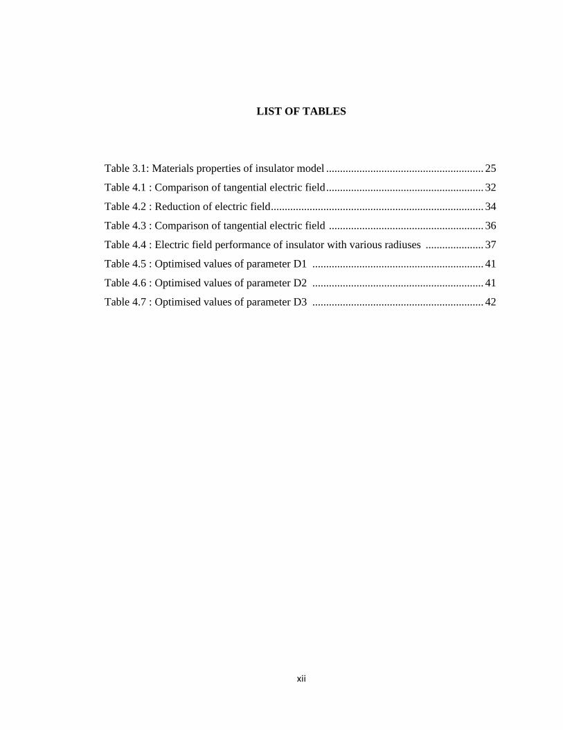
LIST OF TABLES
Table 3.1: Materials properties of insulator model ......................................................... 25
Table 4.1 : Comparison of tangential electric field ......................................................... 32
Table 4.2 : Reduction of electric field ............................................................................. 34
Table 4.3 : Comparison of tangential electric field ........................................................ 36
Table 4.4 : Electric field performance of insulator with various radiuses ..................... 37
Table 4.5 : Optimised values of parameter D1 .............................................................. 41
Table 4.6 : Optimised values of parameter D2 .............................................................. 41
Table 4.7 : Optimised values of parameter D3 .............................................................. 42
][jkjhkhj
Page 10
xiii
LIST OF SYMBOLS AND ABBREVIATIONS
SiR - Silicone Rubber
EPDM - Ethylene Propylene Diene Methylene
EPR - Ethylene Propylene Rubber
FEM - Finite Element Method
BEM - Boundary Element Method
2D - Two Dimension
3D - Three Dimension
FRP - Fiber Reinforced Rod
IEC - International Electric Commission
ZnO - Zinc Oxide
UV - Ultra Violet
HV - High Voltage
kV - Kilo Volt
rms - root mean square
mm - Milimetre
cm - Centimetre
m - Metre
E - Electric Field
F - Force
Q - Charge
εr - Realtive Permittivity
σ - Conductivity
Page 11
1
CHAPTER 1
INTRODUCTION
1.1 Background
Outdoor insulators which are widely used in overhead transmission lines as
suspension material have vital roles in power system distributions. Insulators are made
from dielectric materials such as glass, ceramic and composite materials. An insulator
ideally is a substance which does not allow electric charge to flow through it and has no
effect to electric fields. Therefore, dielectric materials which have high electric
resistance and dielectric constants are used as an insulator. Starting with simple glass
and porcelain insulators, it has rapidly developed since early of the century. These types
of insulators can be considered as classic insulators and may put into the same category
called as ceramic insulators. From research and service experience [1], they are reliable
and cost effective for major outdoor installations. Although porcelain and glass
insulators have good performance over the years [2], their main disadvantages are due to
their bulky size which make them difficult to install in remote area, vulnerable to
vandalism and most importantly is their poor performance in polluted environment.
Page 12
2
Outdoor insulators are subjected to outdoor environmental stresses such as
humidity, temperature and pollution. It has been used in electricity distribution systems
to support, separate or contain conductors at high voltage. Therefore, it has dual
functions as electrical equipment and also as mechanical equipment in the power system
networks. As electrical equipment, it provides electrical support by insulating between
conductors and transmission tower or pole and separating conductors in the transmission
line. Insulators are used as mechanical equipment in providing mechanical support by
supporting the load in the transmission line as shown in Figure 1.1 below.
Figure 1.1 Polymeric outdoor insulators
The modern style of polymeric outdoor insulators was introduced to replace
ceramic insulators. The reason of this replacement was not a failure of ceramic
insulators but the benefits offered by polymeric insulators over ceramic ones. The early
developments of modern polymeric insulators started in 1964 with prototypes for field
installations started in 1967 [3]. A report in 1996 stated that insulators installed in 1969
were performing well [4]. There are different techniques in manufacturing composite
insulators. One of the techniques is to first manufacture the sheds separately and push
them onto the core which is abandoned because these insulators experienced a lot of
problems. The weak spots were the interfaces between the sheds where moisture could
penetrate into the insulator causing internal tracking. The other method of manufacturing
Page 13
3
composite insulators is one shot moulding. This is the most commonly used technique
today. By using this technique, the housing can be chemically bonded to the core.
Therefore, the number of interfaces where moisture can penetrate is minimized.
Despite their lower weight, the easier handling, the reduced installation and
maintenance cost and their better performance under high pollution conditions,
composite insulators are more sensitive to the magnitude of electric field strength. High
values of the electric field intensify the corona effect around conductors and causes
general audio noise, radio noise, partial discharges and premature deterioration of the
insulation quality [5, 6]. Moreover, environmental factors such as heat, ozone, UV
radiation, salt and dust deposition, acid rain and wind are responsible for the gradual loss
of the hydrophobicity of the polymer material [7].
There are many shapes and types of insulators used in power system
transmission with different densities, tensile strengths and performing properties with
the aim to withstand the worst conditions such as surge during lightning and switching
operations which will voltage to spike. Reliability of the insulator is the most important
property that must take into consideration whether it is a polymeric (composite)
insulator or ceramic insulator. The good insulator should offer optimum electrical and
mechanical strengths.
1.2 Problem Statement
The performance of polymeric insulators is important for both dry and wet
condition. The insulators are exposed to various environmental stresses, which include
many forms of precipitation, UV radiation and pollution. Long term problems with
polymeric insulators are related to the degradation of polymer materials used for the
insulator, corona phenomena on the insulator‟s surface and pollution flashover. When
polymeric insulators are installed on power line, the presence of conductors, the
hardware, the tower configuration and also the other two phases of three phase system
may influence the electric field strength in the vicinity of polymeric insulators.
Page 14
4
The presence of pollution layer on composite insulator is very frequent near
industrial, agricultural and coastal areas. Existence of pollution layer and combination
with moisture due to wet weather condition such as dew, fog or drizzle, becomes
conductive and leakage current flows through it. Due to flow of leakage current, dry
bands may form on the insulator surface and the distribution of electric field and
potential to become distorted and flashover may occur.
The study of electric field on polymeric insulator when subject to high voltage
provides an important insight to improve the performance of the insulator. The design of
a post insulator plays an important role in the insulator‟s performance. The insulator‟s
shed profile can affect the water collection on the insulator‟s surface and may influence
the electric field stress distribution along the insulator‟s surface.
Therefore, for the electric field control purpose, it is important to study these
effects from a practical standpoint. The design of end fitting shape of polymeric
insulators need to carefully designed to ensure the occurrence of corona in the vicinity of
end fitting on the insulator to be kept at minimum frequency as possible. The
performance and reliability of insulators may improve with the continuous improvement
in the design.
1.3 Objectives
The main aim of this project is to optimize the electric field distribution around the
insulator and furthermore to improve electric field performance. The objectives to be
achieved are:
a. To simulate and analyse electric field distribution around polymeric insulators.
b. To evaluate the effect of insulator shape and attachment structure towards
electric field performance under various weather conditions.
c. To propose and optimised insulator profile for best electric field distribution and
performance.
Page 15
5
1.4 Scope of Project
For this project, polymeric insulator model chosen to develop is used for 11 kV.
The focuses on this project are as follow:
i. The modelling and simulation work is accomplished using Finite Element
Methods (FEM).
ii. 2D modelling and simulations for more realistic and accurate electric field
computations.
iii. Insulator developed is ideal without considering any attached or nearby structure.
1.5 Thesis Outline
The thesis can be divided in five main chapters. Chapter 1 mainly focuses on the
background of the project which is the problems faced by polymer insulators and the
objectives that driven this project. The limitation of the project has been discussed in
scope of project section.
Chapter 2 briefly discusses on polymeric insulators and factors that affecting insulators
degradation. The influence of electric field on insulator performance and the techniques
to optimize the electric field are reviewed.
In chapter 3, the method to investigate electric field distribution on insulator via
computer software simulations is discussed. Finite element method is employed for
insulator modelling to determine electric potential and field distribution along the
leakage path under dry clean conditions. A model of 11 kV polymer insulators is used to
identify the effectiveness of optimization techniques employed.
Results of the project and analysis are discussed in chapter 4. The results from various
simulation of the insulator model with different parameters such as end fittings design,
configuration of weather sheds shape and installation of corona ring at appropriate
Page 16
6
location are obtained. All the simulation results, discussion and analysis are made to
study the influence of proposed methods on electric field distribution on the insulator.
Finally, chapter 5 presents the conclusions based on the findings from this study. By
referring to to the findings, some recommendations for future investigation are outlined.
Page 17
7
CHAPTER 2
A REVIEW ON POLYMERIC OUTDOOR INSULATOR
2.1 Introduction
Insulators are widely used in electrical power systems to provide electrical
insulation property and mechanical support for overhead transmission lines. There are
three main types of insulator materials that usually used in power system distribution
networks which are ceramic, glass and polymer. Figure 2.1 below shows the
classification of the main types of insulators. It also has many shapes of insulators used
in power system transmission with different densities, tensile strengths and performing
properties. The intentions of high voltage insulators are to withstand any kind of worst
conditions such as lightning and switching operations which may cause voltage to spike.
Page 18
8
Figure 2.1 Classification of power line insulators
Porcelain insulators have a long journey of history. Initially, it has been used in
the telegraph line at the beginning of the fourth decade of 19th
century before the
expansion of the usage for power lines area. In the 1960‟s an insulator having porcelain
sheds supported by an epoxy resin fiberglass rod was developed [40]. However, the
usage was not wide because of further developments in lighter weight polymeric
insulating materials has taken place. Both porcelain and glass have outstanding
insulating properties and weather resistance. However, they are lack in terms of their
bulky size which becomes more difficult to install in remote area, vulnerable to
vandalism and also the performance in polluted area are poor. This is due to its
hydrophilic properties which enable water to easily form a continuous conductive film
along the creepage path. This formation has encouraged the flashover and could cause
the failure in power transmission lines.
2.2 Polymeric Insulators
Polymeric insulators are increasingly being used in both the distribution and
transmission voltage ranges and are steadily capturing a wider share of the market [8].
Before the introduction of polymeric, porcelain and glass have been traditionally used
widely as insulating materials for high voltage power transmission line applications.
They were introduced in 1960‟s and started to be installed in United States in 1970‟s and
Page 19
9
since then, they became major option for utility companies around the world. After the
introduction of polymeric insulators, the privilege to use it as a replacement for glass and
ceramic has tremendously increase globally since the wide range of attractive
advantages offered. They are easy to install due to their light weight and less prone to
damage due to vandalism because of their elasticity surface. One of their major
advantages is their low surface energy [9, 10] and thereby able to maintain a good
hydrophobic surface property in presence of wet conditions such as fog, dew and rain
[11]. Due to their hydrophobic surface, leakage current is reduced since it prevents
water to form solid conducting layer on its surface.
With the improvements in design and manufacturing, it becomes more attractive
to the utility companies around the world to utilize it. The developments of new
materials continue to grow with a number of new insulating materials that have been
developed and the concept of a composite structure which is advanced. Polymeric
insulators consist of a fiberglass core rode covered by weathersheds of skirts of polymer
such as silicone rubber, polytetrafluoroethylene, ethylene propylene diene monomer
(EPDM) and equipped with metal and fittings. Materials such as Ethylene Propylene
Rubber (EPR), Ethylene Propylene Diene Methylene (EPDM) or SiR are used to protect
the core from environmental stresses. Silicone rubber is mainly used for polymer
insulators or composite insulators as housing materials [12]. A housing material should
have the ability to protect the load bearing core and provide sufficient pollution
withstand. Rubbers have been chosen instead of ordinary plastic because of the ability of
the rubber to be flexible enough to follow the changes in dimension caused by
temperature or mechanical load. It is called composite insulators since it has been made
with at least two insulating parts which are a core and housing equipped with end
fittings. Figure 2.2 below shows the cross section for polymeric insulator component.
Page 20
10
Figure 2.2 Cross section of composite insulator
The insulators selection for different voltage rating is depending on minimum
specific creepage distance and IEC60815 standard requirements [41]. Regarding to the
electrical and mechanical characteristics, the insulators are designed to satisfy the
requirements set forth in IEC61109. During designing a perfect insulator, internal and
external discharge activities are consider under normal condition [13].
Despite the numerous advantages offered by polymeric insulators, there are also
some disadvantages of these insulators. The main disadvantages of composite polymeric
insulator are that they are subjected to chemical changes on the surface due to
weathering and from dry band arcing [19], suffered from erosion and tracking which
may lead ultimately to failure of the insulator [20], the difficulty to evaluate life
expectancy, long reliability is unknown and faulty insulators are difficult to detect.
2.3 Electric Field
Electric field influences the performance and the life of insulators. In the design
process, the behaviour of electric field should be given the main consideration to ensure
it will give the satisfaction in term of performance. The intensity of electric field which
is produced due to the potential of dielectric may result in electric stresses upon the
dielectric. The distribution of electric field for polymeric insulators is different
Page 21
11
compared to porcelain insulators. Electric field distribution of a composite insulator
generally is more nonlinear than that of porcelain insulators.
The electric field intensity or known as the electric field strength is defined as the
electrostatic force, F per unit positive test charge, q placed at a particular point, p in a
dielectric [14]. It is denoted by E with the SI unit is Newton per Coulumb which is
equivalent to volt per meter. Since force is a vector, then the electric field is classified as
vector quantity which the direction of the field is taken to be the direction of the force it
would exert on positive test charge. Field strength of 1 v/m represents a potential
difference of one volt between points separated by one meter. The electric field is
radially outward from a positive charge and radially inward toward a negative point
charge. The relationship between electric field and force is given in equation below:
q
FE Equation 1
Referring to the Equation (1), the magnitude of the force is equal to qE and the
direction of the force on a positively charged particle. The force on a negative particle is
opposite to the field direction.
Electric field strength is a quantitative expression of the intensity of an electric
field at a particular location. The electric field strength is often called as the electric field
stress experienced by a dielectric. Field strength of 1 Vm-1
represents a potential
difference of one volt between points separated by one meter. Any electrically charged
object produces an electric field. This field has an effect on other charged objects in the
vicinity. The field strength at a particular distance from an object is directly proportional
to the electric charge in Coulomb on that object. The field strength is inversely
proportional to the distance from a charged object.
Page 22
12
Figure 2.3 Illustration of electric field
Figure 2.3 shows the potential difference Uab between point a and point b having
scalar potential ϕa and ϕb in an electric field, E , which is defined as the work done by an
external source in moving a unit positive charge from b to a.
a
b
baab dxEU Equation 2
The rate of change between potential with distance will give the magnitude of
electric field intensity. When the direction of E is opposite to the direction in which the
potential is increasing most rapidly, the magnitude of the field intensity is at maximum.
max
max
Edx
dUab Equation 3
A physical interpretation of the electric field intensity finding process from the
scalar potential, ϕ is given by Equation (3). The electric field intensity can be obtained
from the potential gradient operation on the potential as shown in equation below:
E Equation 4
Page 23
13
Electric fields in high voltage cause polarization and electric losses in polymeric
insulators [15]. High values of the electric field intensify the corona effect around
conductors and cause in general audio noise, radio noise, partial discharges and
premature deterioration of the insulation quality [16, 17]. When the insulator is exposed
to the higher electric field, it will suffer from the phenomenon of electrical breakdown.
Insulators become conductive when they reach at the breakdown level. In long term,
space charge accumulation can persist within the insulation and its surface and this can
produce localised breakdown at the intense electric field regions which can lead to
erosion on the insulator [18].
2.4 Degradation of Polymeric Insulators
The performance of polymeric insulators may be affected and weakened by
multiple stresses encountered in service. Reservations have been voiced in the past
regarding the use of polymeric insulators, given their organic nature. Continuous service
stress can lead to deterioration of the surface of the properties such as loss of
hydrophobicity, discoloration, chalking and cracking. When the environmental stresses
overwhelm or the severe contamination dominate, the material starts degrading [21].
Polymeric has weaker ionic bonds in contrast to covalent bonds in ceramic because of its
compound chemical bond is subjected to chemical reaction. Beside material and design
of the insulator, other factors that contribute to its degradation and ageing are electrical,
mechanical and environmental stress [22, 23]. Polymers unlike ceramic and glass are
organic materials that can degrade or age under these stresses.
2.4.1 Electrical Stresses
Electrical stresses in polymeric insulators include corona discharges, formation
of dry bands, wetting discharges and insulator flashover. The strength of insulators in
withstanding the electrical stresses is depending on its properties of dielectric materials.
Insulators should have low dielectric losses to be able to deal with the high temperature
and maintain their dielectric strength. The appropriate material properties can help the
insulators to avoid electrical tracking and erosion during service.
Page 24
14
2.4.1.1 Corona Discharges
Corona is phenomenon that has the capability for degrading insulators, and can
cause systems to fail. It is also known as partial discharge where type of localized
emission resulting from transient gaseous ionization in an insulation system when the
voltage stresses or voltage gradient exceeds its critical value. There are three types of
corona which are plume, brush and glow. Plume is the most spectacular corona and it is
called as so because of its general resemblance to a plume. It also has audible
manifestations which are rather intense snapping and hissing sound. Brush corona is a
streamer projecting radially from the conductor. The audible manifestation that is
associated with brush corona is generally a continuous background type of hissing or
frying sound. The glow corona is a very faint, weak light which appears to hug the
conductor‟s surface and there is generally no sound that is associated with it.
Corona can occur within voids in insulators as well as at the conductor‟s or
insulator‟s surface. The formation of corona is dependent upon atmospheric conditions
such as air breakdown humidity and insulator‟s geometry. High potential area for the
formation of corona discharge is at highly curved regions on electrodes, such as sharp
corners, projecting points, edges of metal surfaces or small diameter wires. The high
curvature causes a high potential gradient at these locations. Therefore, to suppress
corona formation, terminals on high voltage equipment are frequently designed with
smooth large diameter with rounded shape and corona rings are often added to insulators
of high voltage transmission lines. The potential distribution depends on the insulator‟s
length and the voltage stress at the terminal that is proportional to the line voltage and
then fall rapidly with the increasing distance from terminal [24].
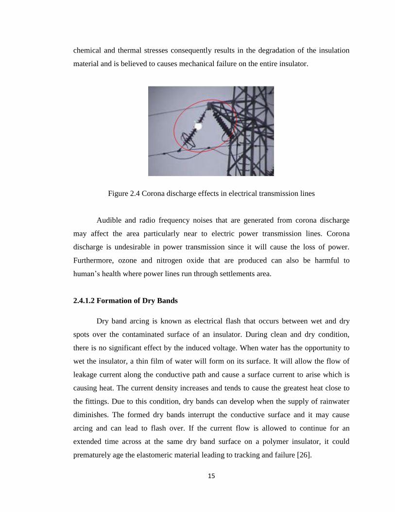
Corona phenomenon in electric power transmission line is shown in Figure 2.3.
Corona accelerates the aging of polymer by producing ozone and nitrogen oxide which
are converted into nitrous and nitric acid in the presence of moisture [25]. It produces
acids that get into the core through voids on the shed. These acids attack the insulation
surface by destroying crosslinks in the polymeric compound and the combined effects of
Page 25
15
chemical and thermal stresses consequently results in the degradation of the insulation
material and is believed to causes mechanical failure on the entire insulator.
Figure 2.4 Corona discharge effects in electrical transmission lines
Audible and radio frequency noises that are generated from corona discharge
may affect the area particularly near to electric power transmission lines. Corona
discharge is undesirable in power transmission since it will cause the loss of power.
Furthermore, ozone and nitrogen oxide that are produced can also be harmful to
human‟s health where power lines run through settlements area.
2.4.1.2 Formation of Dry Bands
Dry band arcing is known as electrical flash that occurs between wet and dry
spots over the contaminated surface of an insulator. During clean and dry condition,
there is no significant effect by the induced voltage. When water has the opportunity to
wet the insulator, a thin film of water will form on its surface. It will allow the flow of
leakage current along the conductive path and cause a surface current to arise which is
causing heat. The current density increases and tends to cause the greatest heat close to
the fittings. Due to this condition, dry bands can develop when the supply of rainwater
diminishes. The formed dry bands interrupt the conductive surface and it may cause
arcing and can lead to flash over. If the current flow is allowed to continue for an
extended time across at the same dry band surface on a polymer insulator, it could
prematurely age the elastomeric material leading to tracking and failure [26].
Page 26
16
2.4.1.3 Wetting Discharges
The water droplets play several roles in the pollution flashover and aging of
composite insulators, because of high permittivity and conductivity of water droplets,
electric field intensity increases at the insulator surface [27]. It may lead to the
breakdown of the insulator even though without the presence of actual contaminants.
The surface corona discharges from water droplets age the weather shed material of the
insulator. This phenomenon has led to the demolishing hydrophobicity and causing the
dispersed of water and adjacent water droplets to coalesce. One of the aging
mechanisms responsibles for the failure of the insulators is discharges on the surface of
polymeric insulators. The discharges usually occur between water droplets on the
insulator‟s surface. This will create several radicals and ionized species that may
chemically react with the insulator‟s surface. Therefore, the original properties of
dielectric materials may change. Water droplets will intensify the electric field strength
on the insulator‟s surface under rainny and foggy conditions.
2.4.1.4 Insulator’s Flashover
Operation of composite insulators is also exposed to the flashover phenomenon
that is caused by switching surge or lightning surge and contamination. It can result in
insulator‟s failure. Contamination increases surface conductivity which causes flashover
to persist after the arc has been initially cleared, allowing subsequent flashover to occur
on reclosed. It is believed that failure due to such flashover is very much dependent on
the duration of the faulty current [35].
When insulators are installed near industrial, agricultural or coastal areas, air
bone particles are deposited on the insulators and the pollution builds up gradually. It
will result in the flow of leakage current during wet weather conditions such as dew, fog
or drizzle. The leakage current density is non-uniformed over the insulator or surface
and in some areas when sufficient heat is developed, it will lead to the formation dry
bands [36]. High electric field intensity across dry bands is caused by voltage
redistribution along the insulator is resulted in the formation of partial arcs. For the
Page 27
17
polymeric insulators, the creation of partial arcs will lead to erosion and chemical
degradation on the insulating material. These partial arcs‟ discharges will elongate along
the insulator‟s profile due to the surface resistance which is sufficiently low and may
eventually cause the insulator‟s flashover.
2.4.2 Environmental Stress
Polymeric insulators perform satisfactorily at the beginning of their service but
will deteriorate due to continuous exposure to the stresses including environmental
stress. Both mechanical and electrical performance of the insulators can affect by the
environmental stresses. The environmental effects include ultraviolet (UV), moisture,
heat, light, atmospheric pressure and biological degradation which are caused by
microorganism in air [28]. Depending on the application and location of the installed
insulator installed, one or more factors can act together to cause aging.
One of the major factors responsible for degradation of polymeric insulator is
ultraviolet light. Insulators are exposed to sunlight under ultraviolet radiation. The main
sources of ultraviolet light are sun, corona formation and dry band arcing activities on
insulator‟s surface. The ability to resist degradation resulting from ultraviolet exposure
is an important factor in determining the service life of insulators. The energy from
sunlight that is destructive to polymers is between 320 nanometers and 270 nanometers
[29]. The absorption of this UV radiation is the result of mechanical and chemical
degradation of the polymer structure which can affect the dielectric and weathering
properties of that polymer. The rate at which the degradation occurs is dependent upon
the intensity and wavelength of the radiation.
The presence of moisture obviously will accelerate the effects on the insulator‟s
surface. This condition is becoming even worse by the presence of surface
contamination due to pollution. Ultraviolet radiation on polymer will result in negative
effects as include:
i. Crazing, checking or cracking of the surface
ii. Loss of hydrophobicity
iii. Discoloration.
Page 28
18
Pollution is one of the main causes of flashover in the insulators. When the
pollutants exist in the air settle on the insulator‟s surface and combine with the humidity
of the fog, rain or dew, it will drive the insulator to fail. Chemical attack occurs due to
pollution of the products and following of discharge activity on the insulator‟s surface.
The mixture of pollutants, plus the humidity forming a layer that can become conductor
and allowing passing currents will facilitate the conditions of short circuit. This is due to
a decrease of the resistance of the insulator surface and could cause the tracking and
erosion surface materials of polymeric insulators.
Water ingress in polymeric insulator occurs in three ways: i) through poor seals
at end fittings, ii) through surface defect or damages, iii) through absorption of water
into the polymeric material itself [30]. Corrosive chemicals and/or ionisable
contaminants that are carried by the water affect the mechanical strength of the FRP rod
and this is known to cause brittle fracture. Water absorption causes depolymerisation as
well as polarisation of the interfaces between the polymer and the fillers. The
permittivity and loss tangent will increase while the dielectric strength will decrease.
2.4.3 Mechanical Stress
Direct mechanical stress on insulators can be tensile, compressive or cantilever
loading [30]. These stresses can cause the failure by damaging the fibre reinforced
plastic (FRP) core. Mechanical stresses usually affect the insulator in combination with
other stresses. Indirect mechanical stresses trap during the manufacturing process. This
will provide arcing regions which would cause tracking and erosion.
2.5 Field Optimisation Techniques
Electric field (E-field) plays a major role in the aging processes of insulators
mainly because it is the factor that triggers partial discharges. The long term and short
term performances of insulators are directly affected by electric field due to corona and
arcing. In order to extend its life span, E-field distribution along insulators must be
controlled and kept below the threshold value. Furthermore, the maintenance cost of the
Page 29
19
insulator can also be reduced. Hence, various techniques can be considered in
controlling E-field distribution along insulators.
2.5.1 End Fittings Design
The design of the end fitting has an influence on the E-field distribution within
the composite insulator on the surface of weather shed material and on the surface of the
metallic end fittings. The large end fittings design with rounded edges tends to reduce
the peak magnitude of the E-field values in close proximity of the end fittings [31].
Figure 2.4 below shows the distribution of E-field for three different end fittings designs.
End fitting closed to the last shed
End fitting at a short distance from the last shed
End fitting partly covered by silicone rubber
Figure 2.5 Examples of the E-field distribution surrounding three
different designs of composite insulator end fittings
Page 30
20
2.5.2 Weather Shed Insulation
In controlling the E-field magnitude, the geometrical shape of polymeric
insulators should be taken into consideration. The weather sheds provide the required
leakage distance and currently are supplied with different materials, shapes, diameters,
thickness and spacing. In the compounding of the weather sheds, fillers are added to
enhance the resistance to tracking and erosion as well as to provide improved
mechanical performance in tensile strength, abrasion resistance, tear strength, modulus
and to reduce flammability.
Gorur et al. [31] has conducted a study on the effect of polymer insulator profile
on the erosion and tracking performance in salt fog. From the study, it was found that
insulators with protected profiles maintained their initial surface hydrophobicity for a
much longer time with low levels of leakage currents than other designs. The self-
cleaning aspect of insulators is important for polymeric insulators with large shed
spacing and insulators with alternating diameter sheds have shown better performance
under both desert and coastal conditions that insulator with straight sheds, which also
allows for reduced shed spacing designs [32]. As such, from the previous studies, it has
shown that the shed profile influences the performance of insulators, particularly under
contaminated conditions.
2.5.3 Corona Ring
A corona ring which is also called an anti-corona ring is a toroid of conductive
material usually metal which is attached to a terminal of high voltage equipment. Corona
ring is used to eliminate or reduce ionisation of the air with associated corona discharge.
The performance and life span of insulator may be affected with corona discharge and
can cause catastrophic insulation failure. Corona ring location and dimension must be
properly installed and chosen since it will mitigate the electric field near the energize
end at the most high electric stress region. Corona rings also improve the voltage
distribution along the insulator string by reducing the percentage of the voltage on the
unit nearest to the power transmission line. Moreover, they also alleviate corona
degradation of non-ceramic materials [33, 34].
Page 31
21
CHAPTER 3
RESEARCH METHODOLOGY
3.1 Introduction
This chapter is discussing on how the work is carried out in order to obtain the
aims of this project. The purpose of this project is to identify the highest electric field
region along the polymeric insulator. After the determination of the highest region,
optimisation technique is used to control and reduce the electric field. The reduced
intensify of electric field can help the insulator to improve its performance and
furthermore will improve its reliability. Several methods have been developed for the
computation of electric fields and potentials along an insulator string.
For this project development, numerical computational technique has been
applied. The potentials and electric fields distribution along developed polymeric
insulator has been evaluated by using Finite Element Method (FEM) computational
simulation.
Page 32
22
3.2 Finite Element Method
Finite element method (FEM) is a numerical analysis technique which is used to
obtain solutions to the differential equations. It has been applied widely in a variety of
physical and also non-physical problems. These problems include diversity from solid,
fluid and soil mechanics to electromagnetism or dynamic. The method essentially
consists of assuming the piecewise continuous function for the solution and obtaining
the parameters of the functions in a manner that reduces the error in the solution [39].
The FEM is most convenient for a field with many dielectrics, heterogeneous and
non-linear materials, complex fields and a field containing distributed space charges and
singular point. It is one of the most successful numerical methods for solving
electrostatic field problems because it involves discretization of the domain according to
the anticipated value of field distributions [38]. It is also a flexible method that is well
suited to problems with complicated geometry. The FEM leads to comparatively simpler
techniques for estimating fields at highly curved and thin electrode surfaces with
different dielectric materials.
3.3 COMSOL Multiphysics
Finite elements simulation for the developed insulator is carried out using
COMSOL Multiphysics software. It is the software that is used as a finite element
analysis, solver and simulation software for various physics and engineering applications
especially coupled phenomena or multiphysics.
There are basically three stages involved which are pre-processing, solving and
post processing. The properties of geometrical and electrical, materials, boundaries and
meshing criteria are the input that involve in the pre-processing stage. In the solving
stage, the boundaries of each geometric condition are applied and the mathematical
model express as differential equations that describe the physical problem is executed.
Page 33
23
For the evaluation of the results, the plot is generated by simulation in terms of variables
or parameters.
3.4 Project Process Flow
In obtaining and analysing electric fields distribution, the process flow of the
project can be simplified in Figure 3.1. The flow chart shows all of the processes
involved starting from the initial stage until the desired results is obtained.
Figure 3.1 Flow chart of electric field optimisation for polymeric insulator
Page 34
24
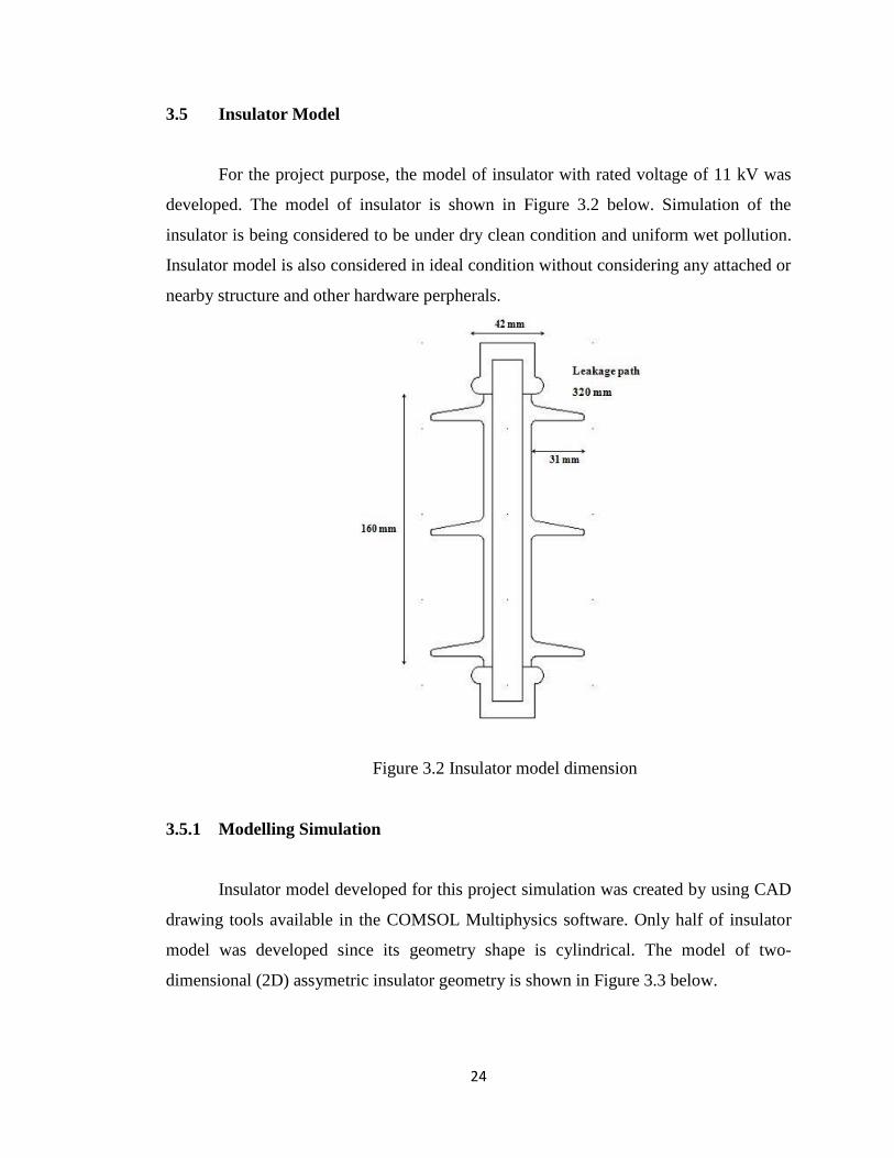
3.5 Insulator Model
For the project purpose, the model of insulator with rated voltage of 11 kV was
developed. The model of insulator is shown in Figure 3.2 below. Simulation of the
insulator is being considered to be under dry clean condition and uniform wet pollution.
Insulator model is also considered in ideal condition without considering any attached or
nearby structure and other hardware perpherals.
Figure 3.2 Insulator model dimension
3.5.1 Modelling Simulation
Insulator model developed for this project simulation was created by using CAD
drawing tools available in the COMSOL Multiphysics software. Only half of insulator
model was developed since its geometry shape is cylindrical. The model of two-
dimensional (2D) assymetric insulator geometry is shown in Figure 3.3 below.
Page 35
48
REFERENCES
[1] Hackam, R., “Outdoor high voltage polymeric insulators”, Proceedings of 1998
Interntational Symposium on ISEIM, pp. 1-16, 1998.
[2] R. S. Gorur, D. Shaffner, W. Clark, R. Vinson, D. Ruff, “Utilities Share Their
Insulator Field Experience”, Transmission & Distribution World, pp. 17-27,
2005.
[3] Reynders, J. P., Jandrell, I. R., Reynders, S. M., “ Surface Aging Mechanisms
and Their Relationship To Service Performance of Silicon Rubber Insulation”,
10th
International Symposium On High Voltage Engineering, London, UK, 22-
27th
August, 1999, pp. 54-58.
[4] Hillborg, H., Gedde, U. W., “Hydrophobicity Recovery of Poly Dimethyl
Siloxane After Exposure To Corona Discharges. Polymer”, 1998, 39(10): 1991-
1998.
[5] B. Zhang, S. Han, J. He, R. Zeng, P. Zhu, “Numerical Analysis of Electric Field
Distribution Around Composite Insulator and Head of Transmission Tower”,
IEEE Transactions On Power Delivery, Vol. 21, No. 2, pp. 959-965, April 2006.
[6] R. Boudissa, S. Djafri, A. Haddad, R. Belaicha, R. Bearsch, “ Effect of Insulator
Shape On Surface Discharges and Flashover Under Polluted Conditions”, IEEE
Transactions On Dielectrics and Electrical Insulation, Vol. 12, No. 3, pp. 429-
437, June 2005.
[7] E. Da Silva, S. M. Rowland, “In Service Surface Degradation of MV Composite
Insulators Under Severe Environmental Conditions and Low Electric Stress”,
Annual Report Conference On Electrical Insulation Dielectric Phenomena, pp.
224-227, 2008.
Page 36
49
[8] J. F. Hall, “History and Bibliography of Polymeric Insulator”, IEEE Trans. PD,
Vol. 8, pp. 376-385, 1993.
[9] S. WU, “Polymer Interface and Adhesion”, Marcel Dekker Inc., NY, 1982.
[10] J. Israelachviii, “Intermolecular and Surface Forces”, Academic Press, 1995.
[11] S. H. Kim, E. A. Cherney and R. Hackam, “Hydrophobic Behaviour of
Insulators Coated With RTV Silicone Rubber”, IEEE Trans. EI, VOl. 27, pp.
610-622, 1992.
[12] B. Marungsri, “Fundamental Investigation on Salt Fog Ageing Test of Silicone
Rubber Housing Materials For Outdoor Polymer Insulators”, Doctoral Thesis,
Chubu University, Kasugai, Aichi, Japan, 2006.
[13] R. Abd. Rahman, N. Hadrid, A. Haddad, “Stress Control on Polymeric Outdoors
Insulators”, pp.1-4, UPEC2010, 31stAug–3
rd Sept.2010.
[14] C. Bayliss, B. Hardy, “Transmission and Distribution Electrical Engineering”,
4th
Edition, Elsevier, ISBN 0080969135, 2011.
[15] Celine A. Mahieux, Environmental Degradation in Industrial Composites.
[online] Elsevier, 2005.
[16] T. Zhao, M. G. Comber: “Calculation of Electric Field and Potential
Distribution Along Nonceramic Insulators Considering the Effects of Conductors
and Transmission Towers”, IEEE Transactions On Power Delivery, Vol. 15, No.
1, pp.313-318, January 2000.
[17] B. Zhang, S. Han, J. He, R. Zeng, P. Zhu: “Numerical Analysis of Electric-Field
Distribution Around Composite Insulator and Head of Transmission Tower”,
IEEE Transactions On Power Delivery, Vol. 21, No. 2, pp. 959-965, April 2006.
[18] Varlow B.R., Robertson J. and Donnelly K.P, “Nonlinear fillers in electrical
insulating materials, ” IET Sci. Meas. Technol., vol 1 (2), pp. 96-102,2007.
Page 37
50
[19] S. H. Kim, E. A. Chemey, R. Hackam and K. G. Rutheriord, “Chemical Changes
at the Surface of RTV Silicone Rubber Coatings on Insulators During Dry Band
Arcing”, IEEE Trans. DEI, Vol. 1, pp. 106-123, 1994.
[20] R. S. Gorur, E. A. Cherney, R. Hackam and T. Orbeck, “The Electrical
Performance of Polymeric Insulating Materials Under Accelerated Aging in Fog
Chamber”, IEEE Trans. PD, Vol. 3, pp. 1157-1164, 1988.
[21] R. Sundararajan, A. Mohammad, N. Chaipanit, T. Karcher and Z. Liu, “In
Service Aging and Degradation of EPDM Transmission Line Insulators In A
Coastal Environment”, IEEE Trans. DEI, Vol. 11, No. 2, pp. 348-361, 2004.
[22] Spellman C. A., Young H. M., Haddad A., Rowlands A. R., and Waters R. T.,
“Survey of polymeric insulator ageing factors,” in Proceedings of the Eleventh
International Symposium on High Voltage Engineering, Conf. Publ. No. 467,
1999, pp. 160-163, Vol. 164.
[23] Souza, A.L., Lopes, I.J.S., “Electrical field distribution along the surface of high
voltage polymer insulators and its changes under service conditions”, IEEE
International Symposium on ELINSL, pp. 56-59. 2006.
[24] Hartings, R., “Electrical Fields Along a Post Insulator: AC Measurements and
Calculations”, IEEE Transaction on Power Delivery, Vol. 9, pp. 912-918, 1994.
[25] Venkatesulu B. and Thomas M. J., “Corona agind studies on silicone rubber
nanocomposites,“ IEEE Transactions on Dielectrics and Electrical Insulation,
vol. 17, pp. 625-634, 2010.
[26] „Environmental Stresses On External Insulation’, http://electrical- engineering-
portal.com/environmental-stresses-on-external-insulation, Retrieved on 29th
March 2013.
[27] Joneidi, I. A., Shavegeni, A. A. and Mohseni, H., “Electric Field Distribution
Under Water Droplet and Effect of Thickness and Conductivity of Pollution
Page 38
51
Layer on Polymer Insulators Using Finite Element Method”, International
Journal of Computer and Electrical Engineering, Vol. 5, No. 2, April 2013.
[28] M. Amin and M. Salman, “Aging of Polymeric Insulators (An Overview),”
Department of Electrical Engineering, University of Engineering and
Technology, Taxila, Pakistan.
[29] R. A. Bernstorf, R. K. Niedermier and D. S. Winkler, “Polymer Compounds
Used In High Voltage Insulators,” Hubbell Power Systems, The Ohio Brass
Company.
[30] Laughton, M. A., Warne, D. F., “Electrical Engineer’s Reference Book,”
Sixteenth Edition, Newnes Publication, 2002.
[31] R. S. Gorur, E. A. Cherney and R. Hackam, “Polymer Insulator Profiles
Evaluated In a Fog Chamber”, IEEE Trans. On Power Delivery, Vol. 5, No. 2,
April 1990, pp. 1078-1085.
[32] R. Znaidi, “Research and Assessment of Insulator Performance in Marine and
Desert Environment”, Insulator News Marketing Report, pp. 12-22, 2000.
[33] Sima W., Espino-Cortes F.P., Edward A.C. and Jayaram H.S., “Optimization of
Corona Ring Design fo Long-Rod Insulators Using FEM Based Computational
analysis IEEE International Symposium on Electrical Insulation”, Indianapolis,
in USA, 19-22 September 2004, pp. 480-483.
[34] Sima W., Wu K., Yang Q., Sun C., “Corona Ring Design of +/-800 kV DC
Composite Insulator Based on Computer Analysis”, IEEE International
Conference on electrical Insulation and Dielectric Phenomena, October 2006, pp.
457-460.
[35] Karady, G. G. and Brown, R. L., “Flashover Mechanism of Silicone Rubber
Insulators Used For Outdoor Insulation”, IEEE Trans. On Power Delivery,
1995, Vol. 10 (No. 4): pp. 1965-1971.
Page 39
52
[36] Muniraj. C., Krishnamorthi. K. and Chandrasekar. S., “Investigation on
Flashover Development Mechanism of Polymeric Insulators by Time Frequency
Analysis”, J Electrical Eng. Tech., Vol. 8, No. 6, pp. 1503-1511, 2011.
[37] Ilhan. S. and Ozdemir. A., “Effect of Corona Ring Desgin on Electric Field
Intensity and Potential Distribution Along an Insulator String”, IEEE ELECO,
2007.
[38] W. Sima, Q. Yang, “Potential and Electric Field Calculation along an Ice
Covered Composite Insulator with Finite Element Method”, IEEE Proceeding
Generation, Transmission and Distribution, 3, 153, 2006, pp. 343-349.
[39] Dixit. U. S., “Finite Element Method: An Introduction”, Department of
Mechanical Engineering, Indian Institute of Technology Guwahati-781 039,
India.
[40] M. T. Gencoglu, “The Comparison of Ceramic and Non-Ceramic Insulators”, e-
Journal of New World Sciences Academy, Vol. 2, No. 4, 2007.
[41] DD IEC/TS 60815 – 3: 2008 – Selection and dimensioning of high-voltage
insulators intended for use in polluted conditions - Part 3: Polymer insulators for
a.c systems : British Standard Institution Std., 2008.