Optimization and Piloted Simulation Results
of the AH-64D Modern Control Laws
Jeffrey W. Harding
Harding Consulting, Inc.
Kennesaw, Georgia
Mohammadreza H. Mansur
Mark B. Tischler
Aeroflightdynamics Directorate (AMRDEC)
U.S. Army Research, Development, and Engineering Command
Ames Research Center, Moffett Field, California
Scott J. Moody
Richard C. McCann
Aviation Engineering Directorate
U.S. Army Aviation and Missile
Research, Development, and Engineering Center
Redstone Arsenal, Alabama
ABSTRACT
The U.S. Army’s Aviation Engineering Directorate led the first phase of a program to develop modern control laws
(MCLAWS) for the AH-64D Apache Longbow to provide improved handling qualities for hover/low speed flight in a
degraded visual environment. The design approach uses the existing partial authority stability augmentation system to
provide both attitude command attitude hold and translational rate command response types over a useful range of aircraft
velocities and attitudes to reduce pilot workload in degraded visual environments based on the requirements in ADS-33E.
These new response types are integrated into a full envelope set of control laws providing a viable upgrade to the existing
aircraft. Control law gains were optimized relative to handling qualities and control system performance requirements
based on a high fidelity, analytical model drawing on deep system knowledge of relevant hardware and software related
dynamics. A piloted simulation evaluation showed reduced pilot workload and improved handling qualities for the
MCLAWS over the legacy flight control system.
NOTATION
ACAH attitude command attitude hold
DVE degraded visual environment
EDS engineering development simulator
FLYRT FLY Real Time simulation model
FTR force trim release
HQ handling qualities
HQR handling qualities rating
MCLAWS modern control laws
MTE mission task element
PH position hold
RACRS risk and cost reduction system
SAS stability augmentation system
TRC translational rate command
UCE usable cue environment
__________________________
Presented at the American Helicopter Society 63rd
Annual
Forum, Virginia Beach, VA, May 1-3, 2007. Copyright ©
2007 by the American Helicopter Society International, Inc.
All rights reserved.
INTRODUCTION
The Aviation Engineering Directorate led the first phase of
a program to develop modern control laws (MCLAWS) for
the AH-64D. These control laws are aimed at providing
both attitude command attitude hold (ACAH) and
translational rate command (TRC) response types using the
existing partial authority stability augmentation system
(SAS). The goal is to improve hover/low speed handling
qualities in a degraded visual environment (DVE) based on
the requirements of ADS-33E (Ref. 1) to address safety
issues associated with operating in harsh desert conditions
where blowing sand and dust cause brownouts leading to
increased accident rates.
Early MCLAWS development work was documented in a
previous paper by Harding, et al (Ref. 2) where the overall
design approach and the model following architecture were
presented. A key element to the approach was the use of
integrated design tools, including MATLAB/Simulink® for
creating a graphical representation of the control laws,
CIFER® (Comprehensive Identification from Frequency
Responses, Ref. 3) for model identification and
CONDUIT® (Control Designers Unified Interface, Ref. 4)
for control law analysis and optimization. CIFER® and
CONDUIT® were both developed by the U.S. Army
Aeroflightdynamics Directorate.
The program is currently in the final stages of control law
development and has recently concluded preliminary
piloted simulation evaluations in the Camber AH-64D risk
and cost reduction simulator (RACRS) in Huntsville,
Alabama. Funding has been secured for integration and
flight testing phases to be led by The Boeing Company in
Mesa, Arizona. Upcoming work includes a second piloted
simulation evaluation to be conducted in the Boeing
engineering development simulator (EDS) followed by
flight testing scheduled for mid 2008.
This paper describes the AH-64D MCLAWS, including an
overview of the three basic response modes and the
blending strategy employed to produce a full envelope
control law solution. Handling qualities analyses and
control law optimization using CONDUIT® are discussed,
including the impact of differences between the aircraft and
simulation model dynamics on gain optimization. Finally,
results of the preliminary piloted simulation evaluation to
determine handling qualities ratings for several ADS-33E
maneuvers are provided.
MODERN CONTROL LAWS
The AH-64D modern control laws were designed to provide
improved handling qualities in hover/low speed flight by
implementing appropriate response types to meet the
requirements in ADS-33E for DVE conditions. In forward
flight, the control laws are similar to the existing AH-64D
rate feedback system. MCLAWS were developed primarily
as a software upgrade to the existing partial authority SAS.
The resulting design is a three-mode control system with
automatic transitions between ACAH, TRC and rate
response modes at the appropriate flight conditions to meet
the requirements of ADS-33E.
The architecture for MCLAWS uses a model following
approach to provide ACAH in the pitch and roll axes in
hover/low speed. The pitch and roll attitude command
models are described in Reference 2. Pilot inputs are
passed through the command models to produce the desired
rates and attitudes. These are passed through an inverse
plant model to cancel the aircraft dynamics. Comparisons
with the actual rates and attitudes produce feedback signals
to reduce the difference between the two. The yaw and
collective axes at hover use simple rate feedback and pilot
command augmentation, or feed forward, similar to the
legacy control laws.
TRC is achieved by closing the ground speed feedback loop
outside the ACAH attitude loop. Pilot cyclic control inputs
produce ground speed commands which are compared to
the actual ground speed to produce error signals for the
attitude command models. Position hold (PH) takes the
same approach one step further. With PH engaged, the
position feedback loop is closed outside the ground speed
feedback loop resulting in the TRC mode being used to
hold position. This series feedback structure assures that all
feedback loops work together to achieve the same goal.
In forward flight, the control laws provide basic rate
damping in all four control axes similar to the legacy
control system. Roll attitude and velocity holds are
available and are activated by cycling the force trim release
(FTR). Additionally, heading hold and turn coordination
are provided automatically depending on pedal activity and
bank angle. For bank angles within ±4 degrees and no
pedal control inputs, heading hold is active.
Altitude or flight path angle hold is pilot selectable at any
airspeed depending on vertical rate. Altitude hold can be
engaged for vertical rates less than 100 ft/min at hover/low
speed and 200 ft/min in forward flight. Flight path angle
hold works in either descent or climb for vertical rates
above the altitude hold maximum limits. Control is
achieved by varying the vertical rate with longitudinal
ground speed to maintain a constant flight path angle.
Flight path hold automatically transitions to altitude hold
near hover or when the radar altitude goes below a safety
limit to avoid flying into the ground.
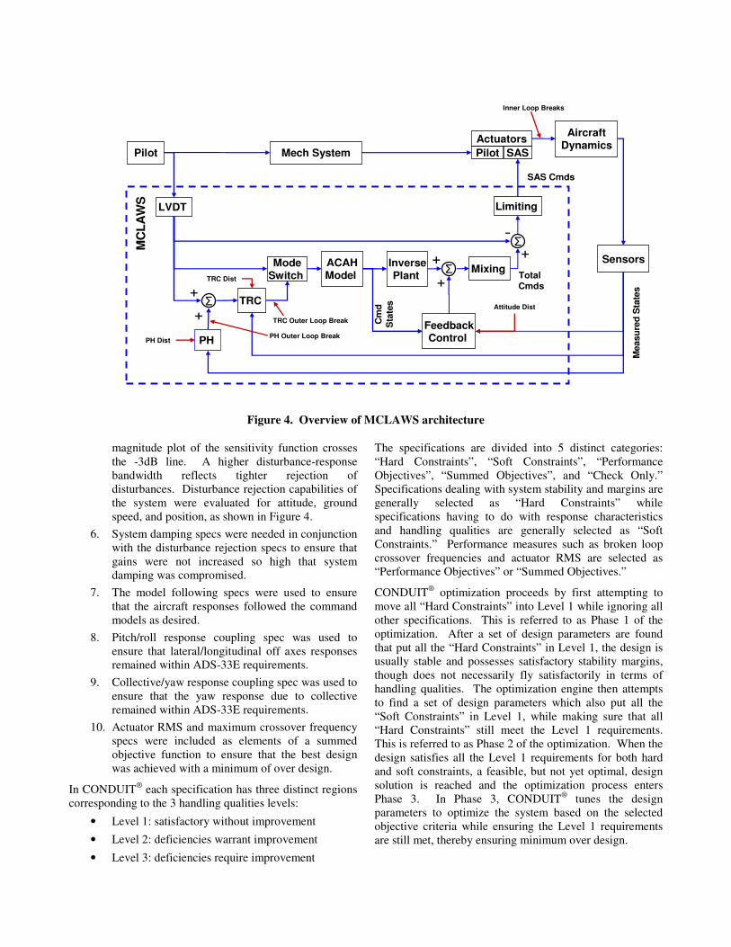
Mode Blending
The MCLAWS response type architecture is shown in
Figure 1. The basic response in hover/low speed is ACAH
which is maintained in sideward and rearward flight out to
the aircraft limit of 45 knots. With increasing forward
ground speed, the system automatically transitions from
ACAH to the forward flight rate mode between 20 and 25
knots. The transition has both ground speed and time based
fade components to limit attitude disturbances for mild or
aggressive transitions. During the transition, attitude
feedback is faded out and rate commands are faded to zero
leaving simple rate feedback. The yaw and collective axes
are rate feedback across the entire flight envelope and do
not have transition regions.
TRC and PH come together as a single pilot selectable
mode. With TRC/PH selected, the system automatically
transitions from ACAH to TRC as the aircraft’s total
ground speed goes below 10 knots. The reverse transition
from TRC to ACAH occurs in one of two ways. Slowly
increasing ground speed beyond 12 knots results in a time
based fade into ACAH. Large control inputs which would
command ground speeds greater than 14 knots cause the
system to switch directly into ACAH mode to facilitate
aggressive maneuvering from hover.
PH is available below five knots by cycling the FTR button
which causes the system to drive the aircraft ground speed
toward zero. Below one knot, position hold automatically
captures position over the ground. Altitude hold and
Longitudinal
Axis (Vx)
Forward Flt
Rate Cmd, Roll Attitude / Velocity Hold, Turn Coordination
Attitude Cmd Attitude Hold (ACAH)
Translational Rate Cmd (TRC)
(Pilot Selectable)
Position Hold (PH)
(Pilot Selectable)
Altitude or Flt Path Hold,
Heading Hold
Rearward Flt
Sideward Flt
Lateral Axis (Vy)
45 KTAS Sideward &
Rearward Flt Limit
VNE
5 knots GS
12 knots GS
20 knots GS
Low/High SpeedTransitionRegion
25 knots GS
Figure 1. MCLAWS response type architecture
heading hold automatically come with position hold. When
the cyclic controls are moved, position is released and the
system reverts back to TRC mode.
Partial Authority Limitations
The amount of augmentation available to change the basic
response of the helicopter is limited by the use of the partial
authority SAS which does not have trim actuators. Despite
this limitation, previous research has shown that most of the
workload reduction in the DVE demonstrated with full
authority ACAH systems can be achieved with a limited
authority flight control system (Refs. 5, 6). The MCLAWS
design included provisions for an expansion of the existing
SAS authority from ±10% in roll, yaw and collective, and
+20/-10% in pitch to a uniform ±20% in all axes. This
expansion would involve a hardware modification to the
SAS actuators and incorporation of improved system
redundancy management algorithms. With the expanded
SAS authority, the MCLAWS modes were designed to
provide the basic ACAH and TRC characteristics over a
useful range of aircraft velocities and attitudes to satisfy the
intent of ADS-33E without persistently saturating the SAS.
ANALYSIS MODEL
A key element in the MCLAWS development was the use
of integrated tools for modeling and analysis. Modeling
was performed using Simulink® to create a graphical
representation of the MLCAWS. Control law development
was based on very accurate linear flight dynamics models
previously identified from flight test data using CIFER®.
The identified models were linked to the control law model
to form a closed loop simulation in Simulink®. Control law
analysis and optimization was performed using
CONDUIT®.
Successful optimization depends on accuracy in the
analysis model which requires incorporating deep system
knowledge regarding aircraft dynamics, mechanical
controls, sensor filtering, and digital system delays. The
aircraft dynamics were represented by separate 12 dof
linear models at hover, 60 knots and 120 knots identified
from frequency response flight test data (Ref. 7). The
models were blended together to provide a continuous
analysis across the speed range of interest. Analytical
models of the actuator dynamics and sensor filtering were
obtained from Boeing. Digital delays associated with the
64 Hz flight computer sampling rate and 50 Hz EGI
(embedded global position system/inertial navigation unit)
sensor update rate were also incorporated into the analysis.
Piloted Simulation Model
The design approach described above produces control
system gains optimized for the actual aircraft (within the
accuracy of the analysis model). In theory, these gains
should be robust enough to perform well in the simulator.
However, discrepancies between the simulation model and
the aircraft can lead to less than optimum performance for
piloted evaluations. The reverse approach of designing
gains in the simulator produces results that often do not
work well in flight test.
The MCLAWS piloted simulation was performed at the
Camber RACRS facility. It uses the FLYRT blade element
flight simulation model developed by Boeing (Ref. 8). The
piloted evaluations documented in this paper were flown
using RACRS’ baseline FLYRT model (v6.1, 1998). Pilot
comments using this model were that the simulation did not
respond like the actual aircraft and the control loader
characteristics gave the cyclic stick a heavy feel, unlike the
aircraft. These issues led to an update of the FLYRT
model, after the initial piloted evaluations being reported in
this paper, to a more recent version available from Boeing
(v2.1.8, 2006), and to modifications to the control loader
force feel characteristics.
With the updated model, pilot comments greatly improved
as the simulator was stated to be a good representation of
the aircraft within the limitations of the fixed base
simulation environment. Nevertheless, even with the new
model simulation work using optimized gain sets for
MCLAWS revealed increased overshoots or oscillations in
the lateral axis response that were not evident in the
analysis. To address this issue, frequency response data
were collected to quantify the updated FLYRT model
dynamics at hover.
Piloted frequency sweeps were flown in the simulator with
the SAS-off. Data analysis showed the overall match
between FLYRT and flight test data was very good. This
reinforced pilot comments for the updated FLYRT model.
The data were used to identify a 6 dof linear model of
FLYRT using the same techniques used to identify the
flight test models. This provided an equivalent linear
FLYRT model for control law analysis. The goal was to
expose potential dynamic differences between the aircraft
and simulator in order to understand their impact on
optimized control law gains.
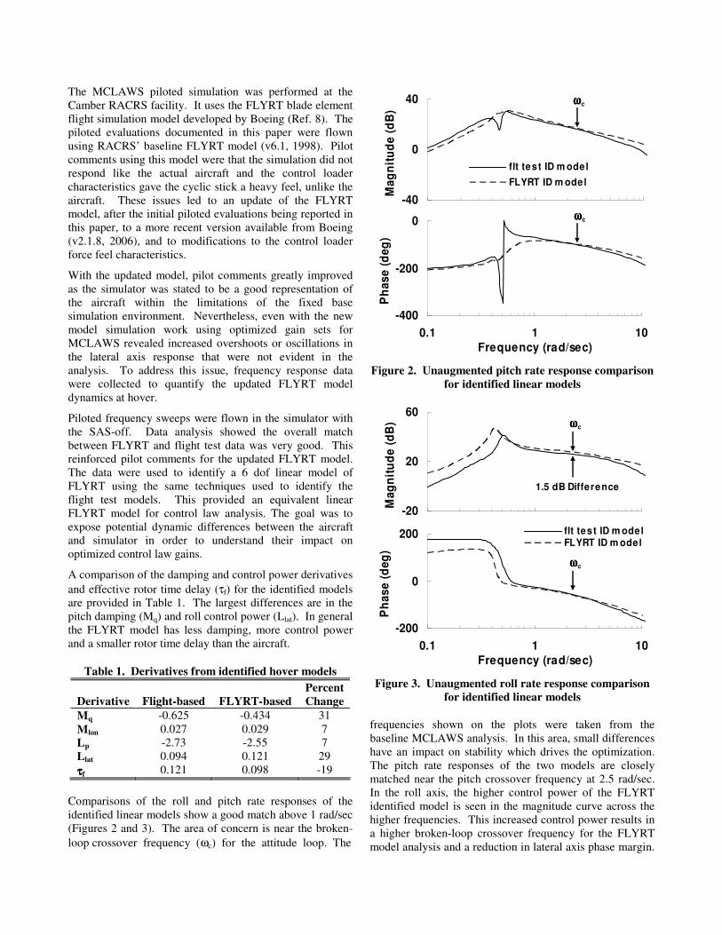
A comparison of the damping and control power derivatives
and effective rotor time delay (τf) for the identified models
are provided in Table 1. The largest differences are in the
pitch damping (Mq) and roll control power (Llat). In general
the FLYRT model has less damping, more control power
and a smaller rotor time delay than the aircraft.
Table 1. Derivatives from identified hover models
Derivative
Flight-based
FLYRT-based
Percent
Change
Mq -0.625 -0.434 31
Mlon 0.027 0.029 7
Lp -2.73 -2.55 7
Llat 0.094 0.121 29
ττττf 0.121 0.098 -19
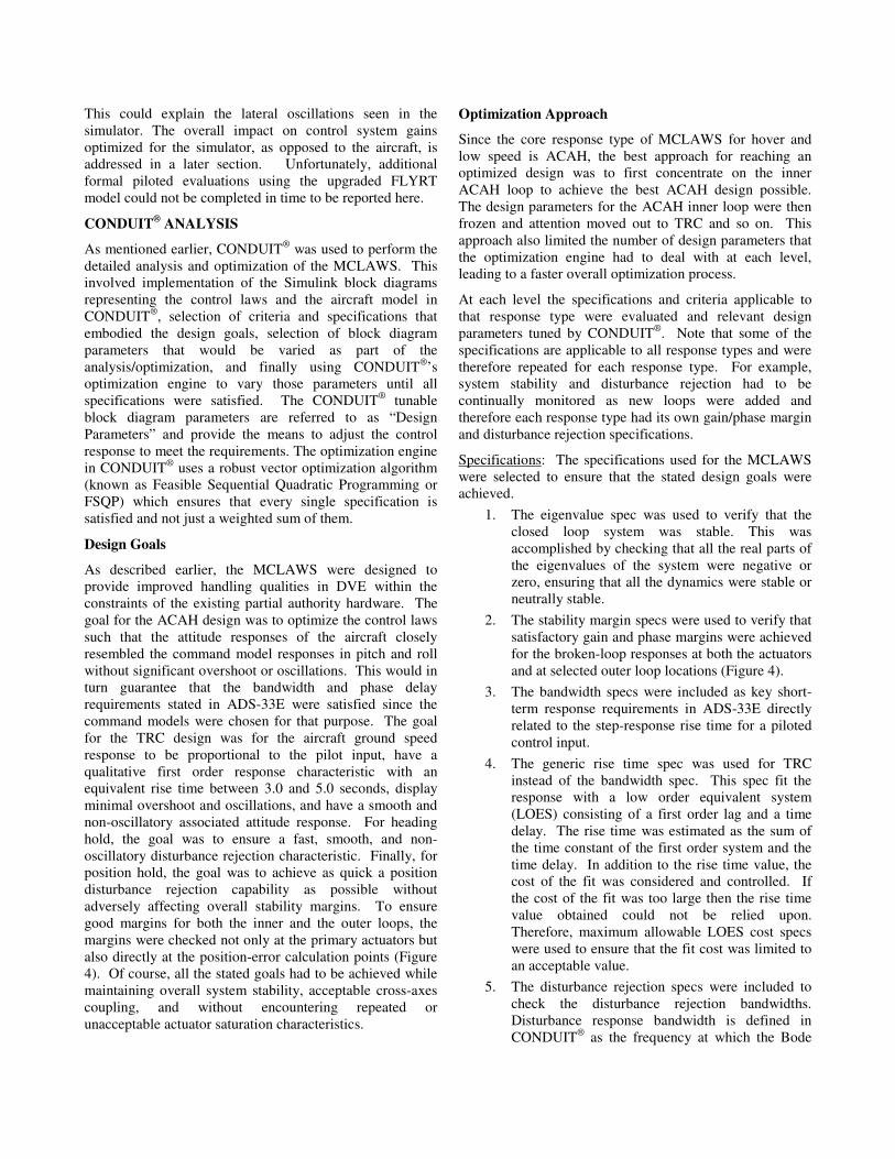
Comparisons of the roll and pitch rate responses of the
identified linear models show a good match above 1 rad/sec
(Figures 2 and 3). The area of concern is near the broken-
loop crossover frequency (ωc) for the attitude loop. The
-40
0
40
Ma
gn
itu
de
(d
B)
flt test ID m odel
FLYRT ID m odel
-400
-200
0
0.1 1 10
Frequency (rad/sec)
Ph
as
e (
de
g)
ωωωωc
ωωωωc
Figure 2. Unaugmented pitch rate response comparison
for identified linear models
-20
20
60
Ma
gn
itu
de
(d
B)
1.5 dB Difference
-200
0
200
0.1 1 10
Frequency (rad/sec)
Ph
as
e (
de
g)
flt test ID m odelFLYRT ID m odel
ωωωωc
ωωωωc
Figure 3. Unaugmented roll rate response comparison
for identified linear models
frequencies shown on the plots were taken from the
baseline MCLAWS analysis. In this area, small differences
have an impact on stability which drives the optimization.
The pitch rate responses of the two models are closely
matched near the pitch crossover frequency at 2.5 rad/sec.
In the roll axis, the higher control power of the FLYRT
identified model is seen in the magnitude curve across the
higher frequencies. This increased control power results in
a higher broken-loop crossover frequency for the FLYRT
model analysis and a reduction in lateral axis phase margin.
This could explain the lateral oscillations seen in the
simulator. The overall impact on control system gains
optimized for the simulator, as opposed to the aircraft, is
addressed in a later section. Unfortunately, additional
formal piloted evaluations using the upgraded FLYRT
model could not be completed in time to be reported here.
CONDUIT® ANALYSIS
As mentioned earlier, CONDUIT® was used to perform the
detailed analysis and optimization of the MCLAWS. This
involved implementation of the Simulink block diagrams
representing the control laws and the aircraft model in
CONDUIT®, selection of criteria and specifications that
embodied the design goals, selection of block diagram
parameters that would be varied as part of the
analysis/optimization, and finally using CONDUIT®’s
optimization engine to vary those parameters until all
specifications were satisfied. The CONDUIT® tunable
block diagram parameters are referred to as “Design
Parameters” and provide the means to adjust the control
response to meet the requirements. The optimization engine
in CONDUIT® uses a robust vector optimization algorithm
(known as Feasible Sequential Quadratic Programming or
FSQP) which ensures that every single specification is
satisfied and not just a weighted sum of them.
Design Goals
As described earlier, the MCLAWS were designed to
provide improved handling qualities in DVE within the
constraints of the existing partial authority hardware. The
goal for the ACAH design was to optimize the control laws
such that the attitude responses of the aircraft closely
resembled the command model responses in pitch and roll
without significant overshoot or oscillations. This would in
turn guarantee that the bandwidth and phase delay
requirements stated in ADS-33E were satisfied since the
command models were chosen for that purpose. The goal
for the TRC design was for the aircraft ground speed
response to be proportional to the pilot input, have a
qualitative first order response characteristic with an
equivalent rise time between 3.0 and 5.0 seconds, display
minimal overshoot and oscillations, and have a smooth and
non-oscillatory associated attitude response. For heading
hold, the goal was to ensure a fast, smooth, and non-
oscillatory disturbance rejection characteristic. Finally, for
position hold, the goal was to achieve as quick a position
disturbance rejection capability as possible without
adversely affecting overall stability margins. To ensure
good margins for both the inner and the outer loops, the
margins were checked not only at the primary actuators but
also directly at the position-error calculation points (Figure
4). Of course, all the stated goals had to be achieved while
maintaining overall system stability, acceptable cross-axes
coupling, and without encountering repeated or
unacceptable actuator saturation characteristics.
Optimization Approach
Since the core response type of MCLAWS for hover and
low speed is ACAH, the best approach for reaching an
optimized design was to first concentrate on the inner
ACAH loop to achieve the best ACAH design possible.
The design parameters for the ACAH inner loop were then
frozen and attention moved out to TRC and so on. This
approach also limited the number of design parameters that
the optimization engine had to deal with at each level,
leading to a faster overall optimization process.
At each level the specifications and criteria applicable to
that response type were evaluated and relevant design
parameters tuned by CONDUIT®. Note that some of the
specifications are applicable to all response types and were
therefore repeated for each response type. For example,
system stability and disturbance rejection had to be
continually monitored as new loops were added and
therefore each response type had its own gain/phase margin
and disturbance rejection specifications.
Specifications: The specifications used for the MCLAWS
were selected to ensure that the stated design goals were
achieved.
1. The eigenvalue spec was used to verify that the
closed loop system was stable. This was
accomplished by checking that all the real parts of
the eigenvalues of the system were negative or
zero, ensuring that all the dynamics were stable or
neutrally stable.
2. The stability margin specs were used to verify that
satisfactory gain and phase margins were achieved
for the broken-loop responses at both the actuators
and at selected outer loop locations (Figure 4).
3. The bandwidth specs were included as key short-
term response requirements in ADS-33E directly
related to the step-response rise time for a piloted
control input.
4. The generic rise time spec was used for TRC
instead of the bandwidth spec. This spec fit the
response with a low order equivalent system
(LOES) consisting of a first order lag and a time
delay. The rise time was estimated as the sum of
the time constant of the first order system and the
time delay. In addition to the rise time value, the
cost of the fit was considered and controlled. If
the cost of the fit was too large then the rise time
value obtained could not be relied upon.
Therefore, maximum allowable LOES cost specs
were used to ensure that the fit cost was limited to
an acceptable value.
5. The disturbance rejection specs were included to
check the disturbance rejection bandwidths.
Disturbance response bandwidth is defined in
CONDUIT® as the frequency at which the Bode
Mech SystemPilot
Sensors
-
+
+ +
SAS Cmds
Measu
red
Sta
tes
Cm
d
Sta
tes
Total Cmds
MC
LA
WS
Actuators
Pilot SAS
InversePlant
AircraftDynamics
ACAHModel
FeedbackControl
Mixing
TRC
PH
Limiting
Σ
Σ
LVDT
ΣMode
Switch
+
+
TRC Outer Loop Break
PH Outer Loop Break
Inner Loop Breaks
PH Dist
TRC Dist
Attitude Dist
Figure 4. Overview of MCLAWS architecture
magnitude plot of the sensitivity function crosses
the -3dB line. A higher disturbance-response
bandwidth reflects tighter rejection of
disturbances. Disturbance rejection capabilities of
the system were evaluated for attitude, ground
speed, and position, as shown in Figure 4.
6. System damping specs were needed in conjunction
with the disturbance rejection specs to ensure that
gains were not increased so high that system
damping was compromised.
7. The model following specs were used to ensure
that the aircraft responses followed the command
models as desired.
8. Pitch/roll response coupling spec was used to
ensure that lateral/longitudinal off axes responses
remained within ADS-33E requirements.
9. Collective/yaw response coupling spec was used to
ensure that the yaw response due to collective
remained within ADS-33E requirements.
10. Actuator RMS and maximum crossover frequency
specs were included as elements of a summed
objective function to ensure that the best design
was achieved with a minimum of over design.
In CONDUIT® each specification has three distinct regions
corresponding to the 3 handling qualities levels:
• Level 1: satisfactory without improvement
• Level 2: deficiencies warrant improvement
• Level 3: deficiencies require improvement
The specifications are divided into 5 distinct categories:
“Hard Constraints”, “Soft Constraints”, “Performance
Objectives”, “Summed Objectives”, and “Check Only.”
Specifications dealing with system stability and margins are
generally selected as “Hard Constraints” while
specifications having to do with response characteristics
and handling qualities are generally selected as “Soft
Constraints.” Performance measures such as broken loop
crossover frequencies and actuator RMS are selected as
“Performance Objectives” or “Summed Objectives.”
CONDUIT® optimization proceeds by first attempting to
move all “Hard Constraints” into Level 1 while ignoring all
other specifications. This is referred to as Phase 1 of the
optimization. After a set of design parameters are found
that put all the “Hard Constraints” in Level 1, the design is
usually stable and possesses satisfactory stability margins,
though does not necessarily fly satisfactorily in terms of
handling qualities. The optimization engine then attempts
to find a set of design parameters which also put all the
“Soft Constraints” in Level 1, while making sure that all
“Hard Constraints” still meet the Level 1 requirements.
This is referred to as Phase 2 of the optimization. When the
design satisfies all the Level 1 requirements for both hard
and soft constraints, a feasible, but not yet optimal, design
solution is reached and the optimization process enters
Phase 3. In Phase 3, CONDUIT® tunes the design
parameters to optimize the system based on the selected
objective criteria while ensuring the Level 1 requirements
are still met, thereby ensuring minimum over design.
Selection of initial design parameters: CONDUIT®
optimization proceeds much more smoothly and rapidly if
the design parameters are assigned initial values based on
the user’s knowledge of the system. This is especially true
of the design parameters which directly affect system
stability margins. CONDUIT® can be used in manual mode
to experiment with initial values for these design
parameters. For example, the broken loop responses of the
system can be plotted and the value of the angular rate
feedback in each axes varied until desired crossover
frequencies are achieved in all axes. The value of the
attitude feedback gains can then be adjusted until
satisfactory phase margins have been achieved. The
resulting attitude and rate gains are not the optimized
values; however, they provide a good starting point for the
optimization engine. This and similar approaches were
used to arrive at starting values of the design parameters.
Interaction of specs: One of the difficulties encountered
during optimization is the sometimes conflicting
requirements being imposed by the various specs. For
example, the angular attitude disturbance rejection specs
require an increase in the angular attitude feedback gains to
increase the disturbance rejection bandwidths. An increase
in the attitude feedback gains, however, generally result in a
lowering of the broken loop phase curves at crossover, in
turn resulting in a reduction in the phase margins.
Therefore, an increase in the attitude feedback gains needed
by the attitude disturbance rejection specs is opposed by the
gain and phase margin requirements as dictated by the gain
and phase margin specs.
As mentioned before, stability margin specifications are
generally designated as hard constraints which the
optimization engine satisfies before the soft constraints or
objective criteria. Therefore, in most cases the stability
margin specs are satisfied before the disturbance rejection
specs, thus limiting the maximum disturbance rejection
bandwidth that can be achieved. It is possible to achieve
increased disturbance rejection bandwidths while
maintaining satisfactory margins by also varying the
angular rate feedback gain along with the angular attitude
gains. The CONDUIT® optimization engine is well suited
to exploring such interactions and finding compromise
values that satisfy all requirements.
To explore the highest level of disturbance rejection that
can be achieved while maintaining satisfactory stability
margins, a new scheme employing ever increasing design
margins on the disturbance rejection specs was employed.
Taking advantage of the design margin optimization facility
of CONDUIT® and the new capability to impose a design
margin only on a selected set of specs, ever higher
disturbance rejection bandwidths were imposed and the
system re-optimized until no solution could be reached
without breaking the stability margin requirements.
Optimization Results
The CONDUIT® optimization engine was used to optimize
the design parameters of the system until Level 1
requirements were achieved for all the included
performance and handling qualities specs. Then, design
margin optimization, described earlier, was used to
systematically increase the disturbance rejection
capabilities of the design while maintaining satisfactory
margins. Finally, the design was optimized using summed
objectives including actuator RMS and maximum crossover
frequency specs to ensure that the best design was achieved
with a minimum of over design. Table 2 lists the values of
the longitudinal, lateral, and directional design parameters
along with the corresponding values from the AH-64D
legacy flight control system and the percent change
between the two. As may be seen, all values have changed
significantly compared to the legacy design, some by
several orders of magnitude.
Table 2. Optimized design parameters
Design
Parameter
AH64D
Baseline MCLAWS
Percent
Change
Ktheta 0.8594 0.33594 -61
Ktheta_int na 0.01634 -
Kq 0.4655 0.39807 -15
Ku 0.0046 0.13833 2907
Kui 0.00023 0.01127 4800
Kx 0.061 0.17852 193
Kphi 0.4641 0.2907 -37
Kphi_int na 0.06596 -
Kp 0.2149 0.05741 -73
Kv 0.0076 0.08054 960
Kvi 0.00038 0.00745 1861
Ky 0.061 0.18507 203
Kpsi 0.4297 0.2322 -46
Kpsi_int 0.1592 0.04141 -74
Kr 0.376 0.30115 -20
The main display of results in CONDUIT® is the Handling
Qualities (HQ) window (Ref. 4) which graphically displays
the current value of each spec plotted against spec
boundaries as defined by ADS-33E or other sources.
Figure 5 shows the CONDUIT® HQ window for the design
parameters shown in Table 2 and is an overview of the final
optimized results. Note that Figure 5 shows only part of the
complete handling qualities window. Also, note the
emphasis on stability margins and disturbance rejection
characteristics which provide the primary specs for trading
off system performance and stability. Consistent with the
optimization approach already described, both stability
margins and disturbance rejection bandwidths are generally
at or near the Level 1 / Level 2 boundary.
Level 1 Level 2 Level 3 Pitch Roll Yaw
Figure 5. CONDUIT® Handling Qualities window (MCLAWS, partial)
-1 0 1-0.1
-0.05
0
0.05
0.1
Real Axis
Eigenvalues (All)EigLcG1:
Ames Research Center
HAll
0 10 200
20
40
60
80
GM [db]
PM
[d
eg
]
(rigid-body freq. range)StbMgG1: Gain/Phase Margins
HACAH @ actuators
0 10 200
20
40
60
80
GM [db]
PM
[d
eg
]
(rigid-body freq. range)StbMgG1: Gain/Phase Margins
HTRC @ actuators
0 10 200
20
40
60
80
GM [db]
PM
[d
eg
]
(rigid-body freq. range)StbMgG1: Gain/Phase Margins
HPH act, DH act
0 10 200
20
40
60
80
GM [db]
PM
[d
eg
]
(rigid-body freq. range)StbMgG1: Gain/Phase Margins
HPH Outer Loop
0 10 200
20
40
60
80
GM [db]
PM
[d
eg
] (rigid-body freq. range)
StbMgG1: Gain/Phase Margins
MIL-F-9490D
Hpsi FB DH
0 10 200
20
40
60
80
GM [db]
PM
[d
eg
]
(rigid-body freq. range)StbMgG1: Gain/Phase Margins
MIL-F-9490D
HCol HH
0 2 40
0.1
0.2
0.3
0.4
Bandwidth [rad/sec]
Ph
as
e d
ela
y [
se
c]
Other MTEs;UCE>1; Div AttBnwAtH1:Bandwidth (pitch & roll)
SACAH
0 50 1000
0.2
0.4
0.6
0.8
1
LOES Cost
CostCosLoG1:Max. Allowable LOES
STRC LOES 0/1
0 1 21
1.2
1.4
1.6
1.8
2
Bandwidth [rad/sec]
(linear scale)DstBwG1:Dist. Rej. Bnw
SACAH Theta
0 1 21
1.2
1.4
1.6
1.8
2
Bandwidth [rad/sec]
(linear scale)DstBwG1:Dist. Rej. Bnw
SACAH Phi
0 2 41
1.2
1.4
1.6
1.8
2
Bandwidth [rad/sec]
(linear scale)DstBwG1:Dist. Rej. Bnw
SACAH r
0 0.2 0.41
1.2
1.4
1.6
1.8
2
Bandwidth [rad/sec]
(linear scale)DstBwG1:Dist. Rej. Bnw
STRC Vx
0 0.2 0.41
1.2
1.4
1.6
1.8
2
Bandwidth [rad/sec]
(linear scale)DstBwG1:Dist. Rej. Bnw
STRC Vy
0 0.2 0.41
1.2
1.4
1.6
1.8
2
Bandwidth [rad/sec]
(linear scale)DstBwG1:Dist. Rej. Bnw
SPHold X
0 0.2 0.41
1.2
1.4
1.6
1.8
2
Bandwidth [rad/sec]
(linear scale)DstBwG1:Dist. Rej. Bnw
SPHold Y
0 0.5 11
1.2
1.4
1.6
1.8
2
Bandwidth [rad/sec]
(linear scale)DstBwG1:Dist. Rej. Bnw
SDHold psi
0 0.5 11
1.2
1.4
1.6
1.8
2
Bandwidth [rad/sec]
(linear scale)DstBwG1:Dist. Rej. Bnw
SHHold hd
0 1 20
0.2
0.4
0.6
0.8
1
Damping Ratio (Zeta)
GenericEigDpG1:Damping Ratio
SMin Damp ACAH, TRC, PH
0 10 20
-1
-0.5
0
0.5
1
Time [sec]
HldNmH1:Normalized Attitude Hold
ADS-33D
SACAH lat/lon + DH dir
Pro
ble
m N
am
e: A
H6
4D
_M
CL
AW
S_
1 C
as
e: 1
Itera
tion
: 0 P
ag
e 1
Prin
t Tim
e: 0
1-N
ov
-20
06
, 15
:09
0 10 200
20
40
60
80
GM [db]
PM
[d
eg
] (rigid-body freq. range)
StbMgG1: Gain/Phase Margins
HACAH @ actuators
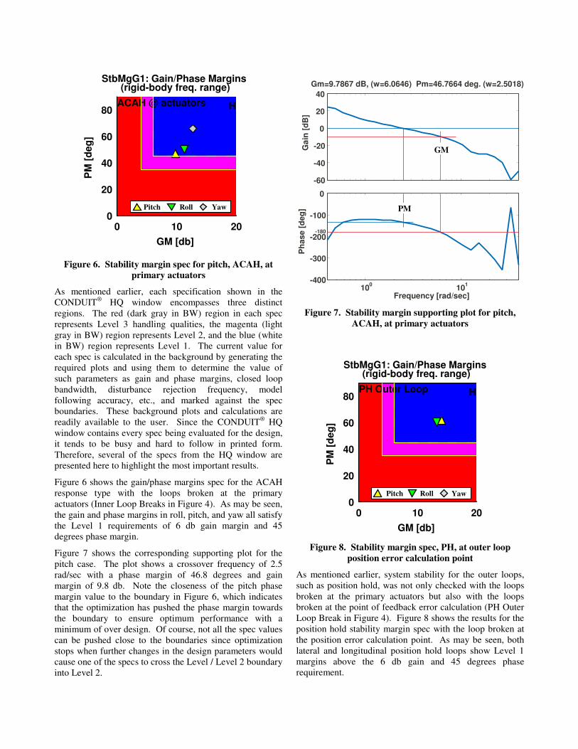
Figure 6. Stability margin spec for pitch, ACAH, at
primary actuators
As mentioned earlier, each specification shown in the
CONDUIT® HQ window encompasses three distinct
regions. The red (dark gray in BW) region in each spec
represents Level 3 handling qualities, the magenta (light
gray in BW) region represents Level 2, and the blue (white
in BW) region represents Level 1. The current value for
each spec is calculated in the background by generating the
required plots and using them to determine the value of
such parameters as gain and phase margins, closed loop
bandwidth, disturbance rejection frequency, model
following accuracy, etc., and marked against the spec
boundaries. These background plots and calculations are
readily available to the user. Since the CONDUIT® HQ
window contains every spec being evaluated for the design,
it tends to be busy and hard to follow in printed form.
Therefore, several of the specs from the HQ window are
presented here to highlight the most important results.
Figure 6 shows the gain/phase margins spec for the ACAH
response type with the loops broken at the primary
actuators (Inner Loop Breaks in Figure 4). As may be seen,
the gain and phase margins in roll, pitch, and yaw all satisfy
the Level 1 requirements of 6 db gain margin and 45
degrees phase margin.
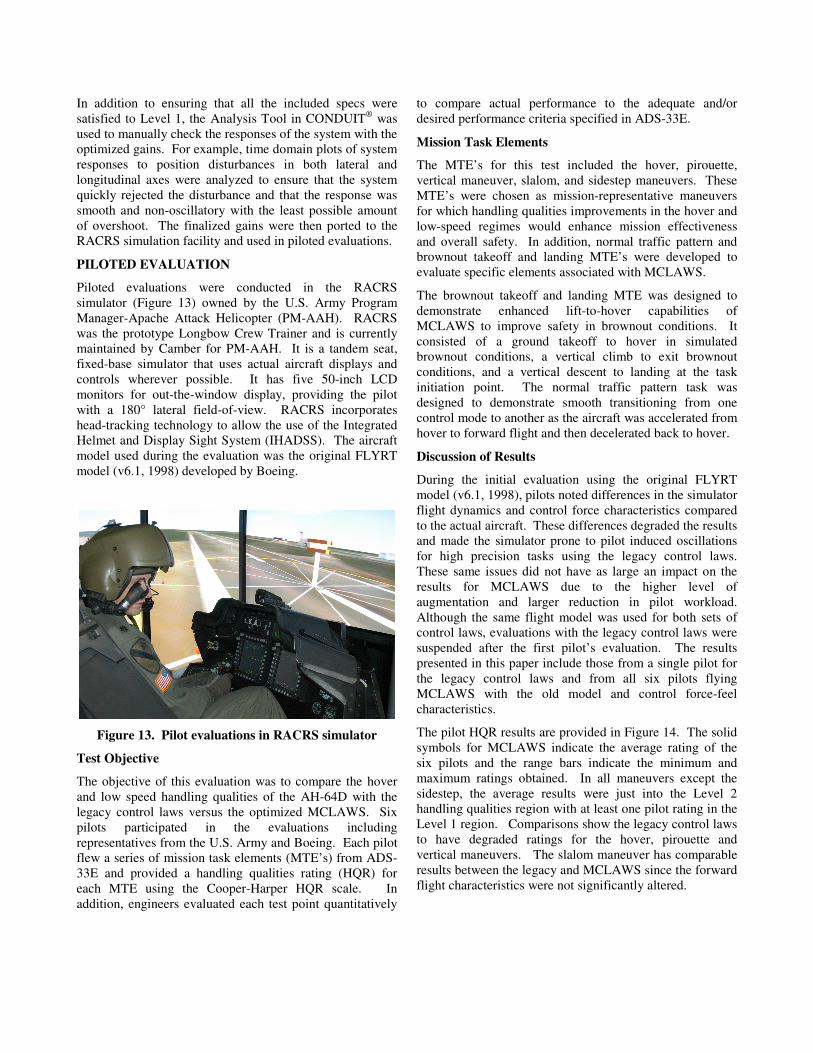
Figure 7 shows the corresponding supporting plot for the
pitch case. The plot shows a crossover frequency of 2.5
rad/sec with a phase margin of 46.8 degrees and gain
margin of 9.8 db. Note the closeness of the pitch phase
margin value to the boundary in Figure 6, which indicates
that the optimization has pushed the phase margin towards
the boundary to ensure optimum performance with a
minimum of over design. Of course, not all the spec values
can be pushed close to the boundaries since optimization
stops when further changes in the design parameters would
cause one of the specs to cross the Level / Level 2 boundary
into Level 2.
-60
-40
-20
0
20
40
Ga
in [
dB
]
Gm=9.7867 dB, (w=6.0646) Pm=46.7664 deg. (w=2.5018)
100
101
-400
-300
-200
-100
0
Frequency [rad/sec]P
hase
[d
eg
]
-180
Figure 7. Stability margin supporting plot for pitch,
ACAH, at primary actuators
0 10 200
20
40
60
80
GM [db]
PM
[d
eg
]
(rigid-body freq. range)StbMgG1: Gain/Phase Margins
HPH Outer Loop
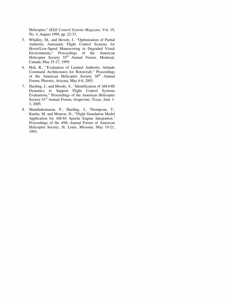
Figure 8. Stability margin spec, PH, at outer loop
position error calculation point
As mentioned earlier, system stability for the outer loops,
such as position hold, was not only checked with the loops
broken at the primary actuators but also with the loops
broken at the point of feedback error calculation (PH Outer
Loop Break in Figure 4). Figure 8 shows the results for the
position hold stability margin spec with the loop broken at
the position error calculation point. As may be seen, both
lateral and longitudinal position hold loops show Level 1
margins above the 6 db gain and 45 degrees phase
requirement.
Roll Pitch Yaw
GM
PM Pitch Roll Yaw
0 2 40
0.1
0.2
0.3
0.4
Bandwidth [rad/sec]
Ph
ase d
ela
y [
sec]
Other MTEs;UCE>1; Div AttBnwAtH1:Bandwidth (pitch & roll)
SACAH
Min Damp ACAH, TRC, PH
Pro
ble
m N
am
e: A
H64D
_M
CL
AW
S_1 C
ase: 1
Itera
tion
: 0 P
ag
e 1
Prin
t Tim
e: 0
1-N
ov-2
006, 1
5:0
9
Figure 9. Bandwidth spec, ACAH
-40
-20
0
20
Ga
in [
dB
]
100
101
-300
-200
-100
0
Frequency [rad/sec]
Ph
as
e [
de
g]
wBWphase=2.6856-135
-180
Figure 10. Bandwidth spec supporting plot for pitch,
ACAH
Figure 9 shows the bandwidth spec for ACAH with the
optimized design parameters shown in Table 2. It can be
seen that the ADS-33E bandwidth and phase delay
requirements are satisfied for all axes. It should be noted
that the primary contributor to system bandwidth for a
model following design is the command model and
therefore the results here indicate that the selected
command models are satisfactory.
Figure 10 shows the supporting bandwidth plot for the pitch
case. For an attitude response type, ADS-33E defines the
bandwidth as the 45 degree phase bandwidth which is
around 2.7 rad/sec in this case. The phase delay value is
calculated using the point of 180 degrees of phase and a
point at twice that frequency.
0 1 21
1.2
1.4
1.6
1.8
2
Bandwidth [rad/sec]
(linear scale)DstBwG1:Dist. Rej. Bnw
SACAH Theta
Figure 11. Pitch attitude disturbance rejection spec,
ACAH
-40
-20
0
20
Ga
in [
dB
]
BW=0.59
10-1
100
101
-400
-300
-200
-100
0
Frequency [rad/sec]
Ph
as
e [
de
g]
-3
Figure 12. Pitch attitude disturbance rejection spec
supporting plot, ACAH
Figure 11 shows the pitch attitude disturbance rejection
spec and shows that the pitch attitude disturbance response
has a bandwidth of almost 0.6 rad/sec. As mentioned
earlier, the Level 1 / Level 2 boundaries of the disturbance
rejection specs were continually moved to the right (higher
bandwidth) using design margin optimization until system
damping was compromised. In effect, the Level 1 / Level 2
boundaries of the disturbance rejection specs were used as
tuning knobs to maximize the disturbance rejection
capabilities of the system.
Finally, Figure 12 shows the supporting plot for the pitch
attitude disturbance rejection spec and depicts the
calculation of the 0.6 rad/sec bandwidth at -3 db of gain.
Roll Pitch Yaw
Pitch
In addition to ensuring that all the included specs were
satisfied to Level 1, the Analysis Tool in CONDUIT® was
used to manually check the responses of the system with the
optimized gains. For example, time domain plots of system
responses to position disturbances in both lateral and
longitudinal axes were analyzed to ensure that the system
quickly rejected the disturbance and that the response was
smooth and non-oscillatory with the least possible amount
of overshoot. The finalized gains were then ported to the
RACRS simulation facility and used in piloted evaluations.
PILOTED EVALUATION
Piloted evaluations were conducted in the RACRS
simulator (Figure 13) owned by the U.S. Army Program
Manager-Apache Attack Helicopter (PM-AAH). RACRS
was the prototype Longbow Crew Trainer and is currently
maintained by Camber for PM-AAH. It is a tandem seat,
fixed-base simulator that uses actual aircraft displays and
controls wherever possible. It has five 50-inch LCD
monitors for out-the-window display, providing the pilot
with a 180° lateral field-of-view. RACRS incorporates
head-tracking technology to allow the use of the Integrated
Helmet and Display Sight System (IHADSS). The aircraft
model used during the evaluation was the original FLYRT
model (v6.1, 1998) developed by Boeing.
Figure 13. Pilot evaluations in RACRS simulator
Test Objective
The objective of this evaluation was to compare the hover
and low speed handling qualities of the AH-64D with the
legacy control laws versus the optimized MCLAWS. Six
pilots participated in the evaluations including
representatives from the U.S. Army and Boeing. Each pilot
flew a series of mission task elements (MTE’s) from ADS-
33E and provided a handling qualities rating (HQR) for
each MTE using the Cooper-Harper HQR scale. In
addition, engineers evaluated each test point quantitatively
to compare actual performance to the adequate and/or
desired performance criteria specified in ADS-33E.
Mission Task Elements
The MTE’s for this test included the hover, pirouette,
vertical maneuver, slalom, and sidestep maneuvers. These
MTE’s were chosen as mission-representative maneuvers
for which handling qualities improvements in the hover and
low-speed regimes would enhance mission effectiveness
and overall safety. In addition, normal traffic pattern and
brownout takeoff and landing MTE’s were developed to
evaluate specific elements associated with MCLAWS.
The brownout takeoff and landing MTE was designed to
demonstrate enhanced lift-to-hover capabilities of
MCLAWS to improve safety in brownout conditions. It
consisted of a ground takeoff to hover in simulated
brownout conditions, a vertical climb to exit brownout
conditions, and a vertical descent to landing at the task
initiation point. The normal traffic pattern task was
designed to demonstrate smooth transitioning from one
control mode to another as the aircraft was accelerated from
hover to forward flight and then decelerated back to hover.
Discussion of Results
During the initial evaluation using the original FLYRT
model (v6.1, 1998), pilots noted differences in the simulator
flight dynamics and control force characteristics compared
to the actual aircraft. These differences degraded the results
and made the simulator prone to pilot induced oscillations
for high precision tasks using the legacy control laws.
These same issues did not have as large an impact on the
results for MCLAWS due to the higher level of
augmentation and larger reduction in pilot workload.
Although the same flight model was used for both sets of
control laws, evaluations with the legacy control laws were
suspended after the first pilot’s evaluation. The results
presented in this paper include those from a single pilot for
the legacy control laws and from all six pilots flying
MCLAWS with the old model and control force-feel
characteristics.
The pilot HQR results are provided in Figure 14. The solid
symbols for MCLAWS indicate the average rating of the
six pilots and the range bars indicate the minimum and
maximum ratings obtained. In all maneuvers except the
sidestep, the average results were just into the Level 2
handling qualities region with at least one pilot rating in the
Level 1 region. Comparisons show the legacy control laws
to have degraded ratings for the hover, pirouette and
vertical maneuvers. The slalom maneuver has comparable
results between the legacy and MCLAWS since the forward
flight characteristics were not significantly altered.
0
1
2
3
4
5
6
7
8
9
10
Hover Vertical
Maneuver
Pirouette Slalom Sidestep
Co
op
er-
Ha
rpe
r H
QR
Legacy (pilot A)
MCLAWS (average pilots A-F)
Level 1
"easy"
Level 2
"harder"
Level 3
"very hard"
Figure 14. Handling qualities ratings from piloted simulation
-3
-2
-1
0
1
0 20 40 60 80
Cy
cli
c (
in s
tk)
PitchRoll
-0.2
-0.1
0
0.1
0.2
0 20 40 60 80
Time (sec)
An
gu
lar
Ra
te (
r/s
)
Legacy
-3
-2
-1
0
1
0 20 40 60 80
Cy
cli
c (
in s
tk)
PitchRoll
-0.2
-0.1
0
0.1
0.2
0 20 40 60 80
Time (sec)
An
gu
lar
Ra
te (
r/s
)
MCLAWS
Figure 15. Time histories from legacy control laws vs MCLAWS for the ADS-33E hover maneuver
Figure 15 shows time history data of the pilot cyclic control
inputs and angular rate responses during typical hover
maneuvers. The maneuvers start with a diagonal translation
to the hover board followed by a deceleration to a stabilized
hover. The deceleration starts at about 40 secs in both
cases. Note the increased control activity and angular rate
response for the legacy control laws vs MCLAWS. This
higher level of activity correlates with the degraded HQR
results when flying the legacy control laws. It also
correlates with pilot comments regarding increased
workload while flying this maneuver with the rate response
system versus using the TRC mode with MCLAWS.
The sidestep MTE was rated as the most difficult maneuver
by each pilot. During the sidestep task, the aircraft model
tended to drift aft during deceleration. The evaluation
pilots had difficulty detecting this aft drift due to the lack of
visual cues available at high bank angles. Specifically, the
vertical field-of-view was approximately 45 degrees in the
simulator. Had additional visual cues been available, as in
the actual aircraft or in a “dome” simulator, the pilots
would likely have met the adequate performance
requirements, resulting in improved HQR’s.
All evaluation pilots agreed that the brownout takeoff and
landing MTE was very easy with the MCLAWS engaged.
In fact, the maneuver was flown as a single-axis (collective-
only) task. The normal traffic pattern MTE added value to
the evaluation in that it verified smooth transitions between
the hover, low-speed, and forward-flight control modes and
demonstrated the level flight and turn coordination
capabilities of MCLAWS.
Although this data was influenced by the simulator fidelity
issues described, the evaluation demonstrated the potential
for reduced pilot workload and improved handling qualities
with response types such as ACAH and TRC regardless of
aircraft dynamics or visual environment.
Adjusting Control Law Gains for Simulation
Very limited, piloted simulations were subsequently
conducted using the updated FLYRT model (v2.1.8, 2006).
During these simulations, certain degraded response
characteristics were noted that were not evident in the
analysis. It was thought that the differences between the
linear flight-data-based model used in the analysis and the
FLYRT model used in RACRS were contributing to these
discrepancies. Therefore, the flight-data-based model was
replaced with one generated from FLYRT frequency sweep
data and the CONDUIT® analysis was revisited with the
new model.
Using the FLYRT-based model with the gains optimized
for the flight-data-based model, it was noted that the lateral
phase margin for ACAH response type was less than 45
degrees and that the rise time for lateral TRC was faster
than 3.0 seconds. The optimized gains used with the flight-
data-based model were manually adjusted to bring all specs
into Level 1 with the FLYRT-based model. Table 3 shows
the design parameters that were changed and compares the
new values to those used with the flight-data-based model.
The low phase margin required reductions to the lateral
feedback gains thus impacting the performance of the
closed loop system. A future piloted simulation in RACRS
is planned and will use the upgraded FLYRT model and
these modified gain values which take into account the
response dynamics of the actual model being flown.
Table 3. Design parameter changes to achieve Level 1
with FLYRT-based model
DP
Flight-based
Model
FLYRT-based
Model
Percent
Change
Kx 0.17852 0.18745 5
Kphi 0.2907 0.23256 -20
Kv 0.08054 0.06846 -15
Kpsi 0.2322 0.24381 5
CONCLUSIONS
Modern control laws (MCLAWS) have been developed for
the AH-64D and evaluated in a piloted simulation to
demonstrate improved handling qualities in hover/low
speed flight. Key elements of this work include:
1. The MCLAWS were developed as a full envelope set
of control laws with three separate response types
including ACAH and TRC in hover/low speed and a
rate response in forward flight to provide a flight
control system upgrade to the existing aircraft.
2. CONDUIT® was used for detailed analysis and
optimization of MCLAWS design parameters using a
three stage process including: 1) optimization to Level
1 requirements for performance and handling qualities
specs, 2) design margin optimization to increase
disturbance rejection characteristics while maintaining
Level 1 stability margins, and 3) use of summed
objectives like actuator RMS to prevent over-design.
3. The dynamics of the simulation model impact the
performance of control laws for piloted evaluations.
Degraded stability margins could result in oscillatory
response and require feedback gain reductions.
4. Piloted simulation results demonstrated reduced pilot
workload and improved handling qualities with
MCLAWS versus the legacy control laws for the
hover/low speed MTEs evaluated.
ACKNOWLEDGMENTS
The authors would like to thank Glenn Baldwin and Steve
Mitchell from Camber Corporation and Geoffrey Jeram
from Westar Aerospace and Defense Group, Inc. for their
technical support and assistance with the model and
simulator. The authors would also like to thank the pilots
who participated in the evaluation and Channing Morse
from Morse Flight Test for his valuable insight during early
control law development and simulation evaluation phases.
REFERENCES
1. Anon, “Aeronautical Design Standard, Handling
Qualities Requirements for Military Rotorcraft,” US
Army Aviation and Missile Command, USAAM-
COM, ADS-33E-PRF, 21 March 2000.
2. Harding, J., Moody, S., Jeram, G., Mansur, M.H., and
Tischler, M., “Development of Modern Control Laws
for the AH-64D in Hover/Low Speed Flight,”
Proceedings of the American Helicopter Society 62nd
Annual Forum, Phoenix, Arizona, May 9-11, 2006.
3. Tischler, M., and Remple, R., “Aircraft and Rotorcraft
System Identification: Engineering Methods with
Flight Test Examples,”, AIAA Education Series, 2006.
4. Tischler, M. B., Colbourne, J. D., Cheung, K. K.,
Morel, M. R., Biezad, D. J., Levine, W. S., and
Moldoveanu, V., “A Multidisciplinary Flight Control
Development Environment and Its Application to a
Helicopter,” IEEE Control Systems Magazine, Vol. 19,
No. 4, August 1999, pp. 22-33.
5. Whalley, M., and Howitt, J., “Optimization of Partial
Authority Automatic Flight Control Systems for
Hover/Low-Speed Maneuvering in Degraded Visual
Environments,” Proceedings of the American
Helicopter Society 55th
Annual Forum, Montreal,
Canada, May 25-27, 1999.
6. Hoh, R., “Evaluation of Limited Authority Attitude
Command Architectures for Rotorcraft,” Proceedings
of the American Helicopter Society 58th
Annual
Forum, Phoenix, Arizona, May 6-8, 2003.
7. Harding, J., and Moody, S., “Identification of AH-64D
Dynamics to Support Flight Control Systems
Evaluations,” Proceedings of the American Helicopter
Society 61st
Annual Forum, Grapevine, Texas, June 1-
3, 2005.
8. Shanthakumaran, P., Harding, J., Thompson, T.,
Kuehn, M. and Monroe, D., "Flight Simulation Model
Application for AH-64 Apache Engine Integration,"
Proceedings of the 49th Annual Forum of American
Helicopter Society, St. Louis, Missouri, May 19-21,
1993.