Optimization and Realization of Quadruple-ridge Flared Horn withNew Spline-defined Profiles as a High-efficiency Feed over 4.6–24GHz
Downloaded from: https://research.chalmers.se, 2022-02-05 23:54 UTC
Citation for the original published paper (version of record):Dong, B., Yang, J., Dahlström, J. et al (2019)Optimization and Realization of Quadruple-ridge Flared Horn with New Spline-defined Profiles asa High-efficiency Feed over 4.6–24 GHzIEEE Transactions on Antennas and Propagation, 67(1): 585-590http://dx.doi.org/10.1109/TAP.2018.2874673
N.B. When citing this work, cite the original published paper.
This document was downloaded from http://research.chalmers.se, where it is available in accordance with the IEEE PSPBOperations Manual, amended 19 Nov. 2010, Sec, 8.1.9. (http://www.ieee.org/documents/opsmanual.pdf).
(article starts on next page)
MANUSCRIPT TO TRANSACTION ON ANTENNAS AND PROPAGATIONS 1
Optimization and Realization ofQuadruple-ridge Flared Horn with New
Spline-defined Profiles as a High-efficiency Feedfor Reflectors over 4.6 – 24 GHz
Bin Dong, Jian Yang, Senior Member, IEEE,Jens Dahlstrom, Jonas Flygare, Miroslav Pantaleev, and B-
hushan Billade, Member, IEEE,
Abstract—In this paper, we present a new optimization andrealization of a quadruple-ridge flared horn (QRFH) as a feed forreflector antennas of the Square Kilometre Array (SKA) project.The QRFH has been numerically optimized by spline-definedprofiles for both the ridges and the horn sidewall, with a conicalcavity in the back-short for maximum aperture efficiency. Thefinal aperture efficiency better than (for horizontal polarization)or around (for vertical polarization) 78% over 4.6–8 GHz, 70%over 8–15 GHz, 65% over 15–20 GHz and 60% over 20–24 GHzin the SKA offset-Gregorian dual-reflector antenna has beenachieved. The realization of the horn has been carried outcarefully by applying several new mechanical design solutionsin order to guarantee the accurate positioning of the ridges, thefeeding pins and a good electrical contact. The measured S11 ismostly better than -10 dB and the predicted aperture efficiencybased on the measured far field patterns agrees well with thesimulated result. System performance, such as the sensitivity andsystem noise temperature, are also estimated and presented.
Index Terms—quadruple-ridge flared horn, wideband feed,spine-defined profiles, aperture efficiency, sensitivity.
I. INTRODUCTION
The Square Kilometre Array (SKA) [1] is an internationalproject for the next-generation radio astronomical observationsat meter- to centimeter-wavelength. It will be an interfero-metric array with a total collecting area of about one millionsquare meters, which in its final stage will provide a sensitivitymore than 50 times higher than the current largest interfer-ometers in the world. The SKA will be constructed in twodistinct phases, SKA1 and SKA2, the former being a subsetof the latter. The SKA1 is now in its pre-construction phase.The Advanced Instrumentation Programme (AIP) is to enhancethe SKA1 baseline and demonstrate an important technologyprototype of direct relevance to SKA2 [2]. Sweden (Onsala
Manuscript received Sept. 19, 2017; revised March 2018. The design, man-ufacturing and testing of the Band-B feed was financed via the Planning Grant“Swedish contributions to the SKA radio-telescope in its pre-constructionphase”, Contract No C0546801. The project has also been partly supportedby STINT project (CH2015-6360).
B. Dong is with the National Astronomical Observatories, Chinese Acade-my of Sciences and CAS Key Laboratory of FAST, NAOC, Chinese Academyof Sciences, 100012, Beijing, China, e-mail:[email protected]. He visitedChalmers University of Technology/Onsala Space Observatory during 2016- 2017, his visit and research were supported by the State ScholarshipFund from the China Scholarship Council (CSC No. 201504910308), theNational Natural Science Foundation of China (11403053) and the OpenProject Program of the Key Laboratory of FAST, NAOC, Chinese Academyof Sciences.
J. Yang is with the Dept. of Electrical Engineering, Chalmers Universityof Technology, S-41296 Gothenburg, Sweden. e-mail:[email protected]
J. Dahlstrom, J. Flygare, M. Pantaleev, and B. Billade are with OnsalaSpace Observatory, Department of Space, Earth and Environment, ChalmersUniversity of Technology, S-41296 Gothenburg, Sweden.
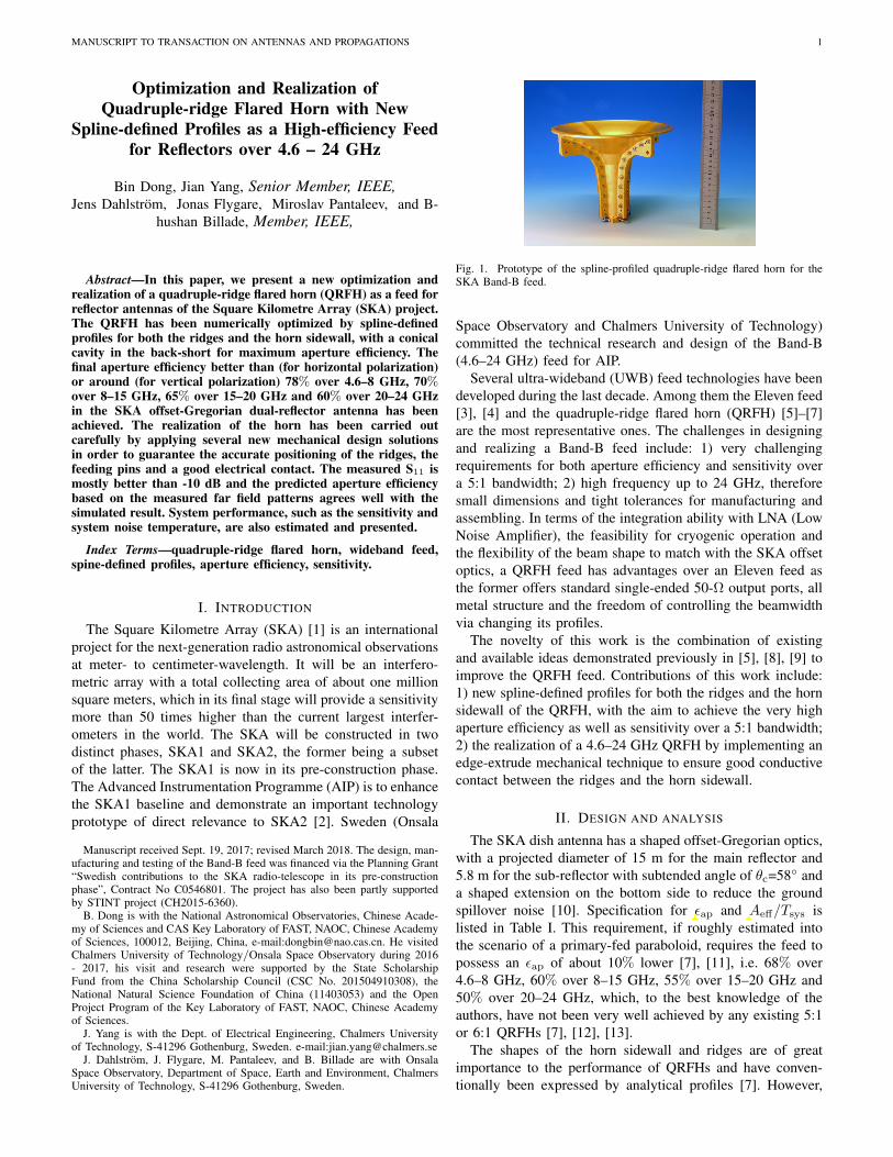
Fig. 1. Prototype of the spline-profiled quadruple-ridge flared horn for theSKA Band-B feed.
Space Observatory and Chalmers University of Technology)committed the technical research and design of the Band-B(4.6–24 GHz) feed for AIP.
Several ultra-wideband (UWB) feed technologies have beendeveloped during the last decade. Among them the Eleven feed[3], [4] and the quadruple-ridge flared horn (QRFH) [5]–[7]are the most representative ones. The challenges in designingand realizing a Band-B feed include: 1) very challengingrequirements for both aperture efficiency and sensitivity overa 5:1 bandwidth; 2) high frequency up to 24 GHz, thereforesmall dimensions and tight tolerances for manufacturing andassembling. In terms of the integration ability with LNA (LowNoise Amplifier), the feasibility for cryogenic operation andthe flexibility of the beam shape to match with the SKA offsetoptics, a QRFH feed has advantages over an Eleven feed asthe former offers standard single-ended 50-Ω output ports, allmetal structure and the freedom of controlling the beamwidthvia changing its profiles.
The novelty of this work is the combination of existingand available ideas demonstrated previously in [5], [8], [9] toimprove the QRFH feed. Contributions of this work include:1) new spline-defined profiles for both the ridges and the hornsidewall of the QRFH, with the aim to achieve the very highaperture efficiency as well as sensitivity over a 5:1 bandwidth;2) the realization of a 4.6–24 GHz QRFH by implementing anedge-extrude mechanical technique to ensure good conductivecontact between the ridges and the horn sidewall.
II. DESIGN AND ANALYSIS
The SKA dish antenna has a shaped offset-Gregorian optics,with a projected diameter of 15 m for the main reflector and5.8 m for the sub-reflector with subtended angle of θc=58 anda shaped extension on the bottom side to reduce the groundspillover noise [10]. Specification for ϵap and Aeff/Tsys islisted in Table I. This requirement, if roughly estimated intothe scenario of a primary-fed paraboloid, requires the feed topossess an ϵap of about 10% lower [7], [11], i.e. 68% over4.6–8 GHz, 60% over 8–15 GHz, 55% over 15–20 GHz and50% over 20–24 GHz, which, to the best knowledge of theauthors, have not been very well achieved by any existing 5:1or 6:1 QRFHs [7], [12], [13].
The shapes of the horn sidewall and ridges are of greatimportance to the performance of QRFHs and have conven-tionally been expressed by analytical profiles [7]. However,
jian
Inserted Text
aperture efficiency
jian
Inserted Text
sensitivity
MANUSCRIPT TO TRANSACTION ON ANTENNAS AND PROPAGATIONS 2
TABLE ITHE SKA REQUIREMENT FOR ϵap AND Aeff/Tsys OVER BAND B
QRFHs with such profiles suffer from a strong beamwidthvariation over frequency (especially in H-plane) as well asthe bad cross-polarization level (in D-plane, the maximumrelative cross-polar level is only -6 dB [7]), which makes theillumination efficiency ϵill drop towards higher frequenciesand results in a bad polarization efficiency ϵpol and BOR1
efficiency ϵBOR1 . A lot of efforts were made to improve thesesub-efficiencies, such as the utilization of quadraxial feeding[9], [12] and other kinds of aperture shapes [8], which makeϵill higher and more flat, but mostly at the cost of a worsespillover efficiency ϵsp (barely up to 95% [7], [12]). In otherwords, ϵill·ϵsp is still not good enough to meet the Band-B requirement. The quadraxial feeding managed to improvethe relative cross-polar level to -9 dB, but this differentialtechnique needs additional baluns and hence more insertionloss would be introduced. Differential LNAs feeding can beanother alternative, but it is normally more expensive andexhibits higher noise factors.
Spline-defined profile already showed very promising beamperformance in [14] and is also adopted for the Band-B feed[15]. It is more flexible than the analytical profiles and enablesa highly customizable optimization on the feed structure. Afterthe optimization, the new spline-profiled Band-B feed hasfulfilled and been very close to fulfill the SKA requirementfor aperture efficiency for horizontal and vertical polarizationsrespectively, while still keeping the spillover noise temperatureto an acceptable level.
A. The Spline-defined Profiles of Band-B Feed
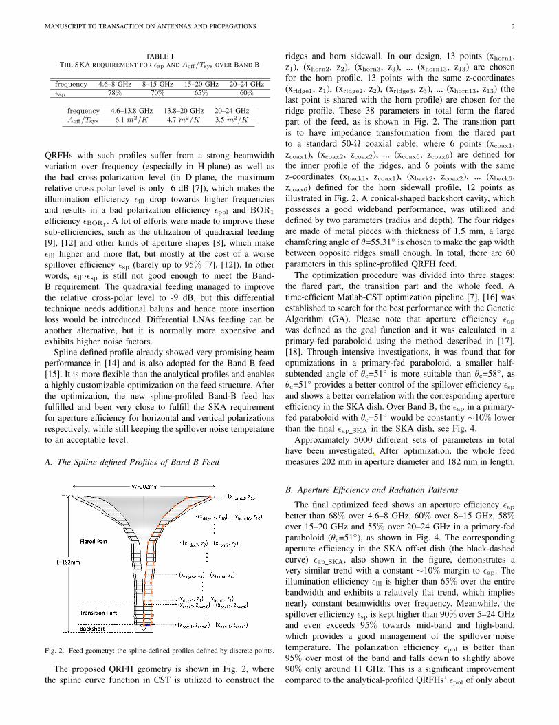
Fig. 2. Feed geometry: the spline-defined profiles defined by discrete points.
The proposed QRFH geometry is shown in Fig. 2, wherethe spline curve function in CST is utilized to construct the
ridges and horn sidewall. In our design, 13 points (xhorn1,z1), (xhorn2, z2), (xhorn3, z3), ... (xhorn13, z13) are chosenfor the horn profile. 13 points with the same z-coordinates(xridge1, z1), (xridge2, z2), (xridge3, z3), ... (xhorn13, z13) (thelast point is shared with the horn profile) are chosen for theridge profile. These 38 parameters in total form the flaredpart of the feed, as is shown in Fig. 2. The transition partis to have impedance transformation from the flared partto a standard 50-Ω coaxial cable, where 6 points (xcoax1,zcoax1), (xcoax2, zcoax2), ... (xcoax6, zcoax6) are defined forthe inner profile of the ridges, and 6 points with the samez-coordinates (xback1, zcoax1), (xback2, zcoax2), ... (xback6,zcoax6) defined for the horn sidewall profile, 12 points asillustrated in Fig. 2. A conical-shaped backshort cavity, whichpossesses a good wideband performance, was utilized anddefined by two parameters (radius and depth). The four ridgesare made of metal pieces with thickness of 1.5 mm, a largechamfering angle of θ=55.31 is chosen to make the gap widthbetween opposite ridges small enough. In total, there are 60parameters in this spline-profiled QRFH feed.
The optimization procedure was divided into three stages:the flared part, the transition part and the whole feed. Atime-efficient Matlab-CST optimization pipeline [7], [16] wasestablished to search for the best performance with the GeneticAlgorithm (GA). Please note that aperture efficiency ϵapwas defined as the goal function and it was calculated in aprimary-fed paraboloid using the method described in [17],[18]. Through intensive investigations, it was found that foroptimizations in a primary-fed paraboloid, a smaller half-subtended angle of θc=51 is more suitable than θc=58, asθc=51 provides a better control of the spillover efficiency ϵspand shows a better correlation with the corresponding apertureefficiency in the SKA dish. Over Band B, the ϵap in a primary-fed paraboloid with θc=51 would be constantly ∼10% lowerthan the final ϵap SKA in the SKA dish, see Fig. 4.
Approximately 5000 different sets of parameters in totalhave been investigated. After optimization, the whole feedmeasures 202 mm in aperture diameter and 182 mm in length.
B. Aperture Efficiency and Radiation Patterns
The final optimized feed shows an aperture efficiency ϵapbetter than 68% over 4.6–8 GHz, 60% over 8–15 GHz, 58%over 15–20 GHz and 55% over 20–24 GHz in a primary-fedparaboloid (θc=51), as shown in Fig. 4. The correspondingaperture efficiency in the SKA offset dish (the black-dashedcurve) ϵap SKA, also shown in the figure, demonstrates avery similar trend with a constant ∼10% margin to ϵap. Theillumination efficiency ϵill is higher than 65% over the entirebandwidth and exhibits a relatively flat trend, which impliesnearly constant beamwidths over frequency. Meanwhile, thespillover efficiency ϵsp is kept higher than 90% over 5–24 GHzand even exceeds 95% towards mid-band and high-band,which provides a good management of the spillover noisetemperature. The polarization efficiency ϵpol is better than95% over most of the band and falls down to slightly above90% only around 11 GHz. This is a significant improvementcompared to the analytical-profiled QRFHs’ ϵpol of only about
jian
Cross-Out
jian
Inserted Text
The optimization procedure was divided into three stages: the only flared part with two symmetric planes and the goal function of maximizing, the only transition part including the back cavity (no symmetric planes) with the goal function of minimizing and the whole feed with one symmetric plane for each polarization and the goal function of both maximizing and minimizing. The reason that we need the last optimization stage of the whole feed is that the sidewall profile of the transition has some effect, though not very strong, on the aperture efficiency. Nevertheless, with the previous stages, much fewer cases are needed for the last stage’s optimization.
jian
Cross-Out
jian
Inserted Text
Approximately XXX, xxxx and yyy sets of parameters have been investigated on optimization stages 1, 2 and 3, respectively, with CPU time of xxx, yyy and zzz hours on a server (say here the performance of the server).
MANUSCRIPT TO TRANSACTION ON ANTENNAS AND PROPAGATIONS 3
Fig. 3. Simulated radiation patterns in E-, D- and H-planes, both co-polar and cross-polar components are shown.
90% across the bandwidth [13]. The BOR1 efficiency ϵBOR1
is around 90% over the band, which is 5∼10% higher thanthat of the QRFHs using analytical profiles [7].
4 6 8 10 12 14 16 18 20 22 240
0.1
0.2
0.3
0.4
0.5
0.6
0.7
0.8
0.9
1
Freq (GHz)
Ape
rtur
e E
ffici
enci
es
εap
εill
εsp
εBOR1
εpol
εph
εap_SKA
Fig. 4. Simulated aperture efficiency and the sub-efficiencies of the optimizedspline-profiled QRFH feed, calculated in a primary-fed paraboloid with half-subtended angle of θc=51.
Fig. 3 shows the simulated radiation patterns in E-(ϕ=0),D-(ϕ=45) and H-(ϕ=90) planes, normalized co-polar as wellas relative cross-polar. The co-polar patterns exhibit verygood Gaussian shapes with sidelobe and backlobe levels wellbelow -20 dB. The beam profiles are nearly constant withfrequency, even in H-plane the fluctuation of nominal 10 dBbeamwidth is only about 2×20, an improvement on thebeam rotational symmetry from the existed QRFH’s H-planebeamwidth fluctuation of 2×(30∼35) [7], [13]. The cross-polar level is most significant in D-plane for BOR and quasi-BOR antennas and the QRFH shows a relative cross-polarlevel below -11 dB in D-plane, another improvement from theanalytical-profiled QRFHs, which is about -6 dB in [7], [13].
III. MECHANICAL REALIZATION
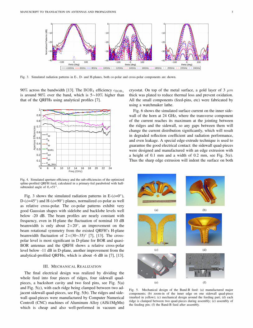
The final electrical design was realized by dividing thewhole feed into four pieces of ridges, four sidewall quad-pieces, a backshort cavity and two feed pins, see Fig. 5(a)and Fig. 5(c), with each ridge being clamped between two ad-jacent sidewall quad-pieces, see Fig. 5(b). The ridges and side-wall quad-pieces were manufactured by Computer NumericalControll (CNC) machines of Aluminum Alloy (AlSi1MgMn)which is cheap and also well-performed in vacuum and
cryostat. On top of the metal surface, a gold layer of 3 µmthick was plated to reduce thermal loss and prevent oxidation.All the small components (feed-pins, etc) were fabricated byusing a watchmaker lathe.
Fig. 6 shows the simulated surface current on the inner side-wall of the horn at 24 GHz, where the transverse componentof the current reaches its maximum at the jointing betweenthe ridges and the sidewall, so any gaps between them willchange the current distribution significantly, which will resultin degraded reflection coefficient and radiation performance,and even leakage. A special edge-extrude technique is used toguarantee the good electrical contact: the sidewall quad-pieceswere designed and manufactured with an edge extrusion witha height of 0.1 mm and a width of 0.2 mm, see Fig. 5(e).Thus the sharp edge extrusion will indent the surface on both
(a) (b)
(c) (d)
(e) (f)
Fig. 5. Mechanical design of the Band-B feed: (a) manufactured majorcomponents; (b) zoom-in of the inner edge on one sidewall quad-piece(marked in yellow); (c) mechanical design around the feeding part; (d) eachridge is clamped between two quad-pieces during assembly; (e) assembly ofthe feeding pin; (f) the Band-B feed after assembly.
MANUSCRIPT TO TRANSACTION ON ANTENNAS AND PROPAGATIONS 4
(a) (b)
Fig. 6. Surface current distribution at 24 GHz (in magnitude, based on CSTsimulation): (a) surface currents on the whole feed; (b) surface currents aroundthe radiation region.
sides of each ridge as the ridge material is a bit softer andwill act like a punching die. With the golden layer this wouldguarantee an extremely good electrical contact after tighteningthe two adjacent sidewall quad-pieces with screws.
A coaxial cable with an inner conductor diameter ofϕ=0.28 mm was chosen as the feeding pin. The inner con-ductor was inserted into the central hole of a spring-loadedcylinder stud embedded within the opposite ridge, which locksthe pin by a chuck, see Fig. 5(f). This design secures the clampof the pin and at the same time allows some small movementsof the material due to heating- and cooling-extension.
IV. MEASURED PERFORMANCE
A. Scattering Parameters
The simulated and measured scattering parameters areshown in Fig. 7. The measured S11 and S22 are mostly below-10 dB across the bandwidth except for around 10.6 GHz and23.2 GHz. At low frequencies, the measured results followthe same trend with simulation, while at high frequencies themeasured reflection coefficient is higher than the simulationfor about 5 dB. The measured port isolation is around -25 dBover the bandwidth. The inconsistency between measurementand simulation is caused mainly by a mechanical error, thaton one ridge the feeding hole was not center-drilled due to adrift of the drill, the corresponding feed pin therefore has tobe slightly bent in order to fit in.
Fig. 7. Measured and simulated S-parameters of the prototype feed.
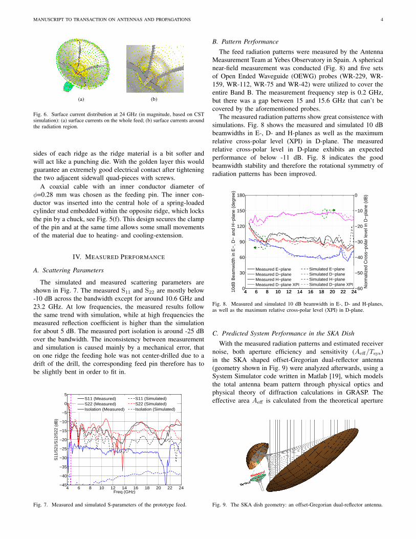
B. Pattern Performance
The feed radiation patterns were measured by the AntennaMeasurement Team at Yebes Observatory in Spain. A sphericalnear-field measurement was conducted (Fig. 8) and five setsof Open Ended Waveguide (OEWG) probes (WR-229, WR-159, WR-112, WR-75 and WR-42) were utilized to cover theentire Band B. The measurement frequency step is 0.2 GHz,but there was a gap between 15 and 15.6 GHz that can’t becovered by the aforementioned probes.
The measured radiation patterns show great consistence withsimulations. Fig. 8 shows the measured and simulated 10 dBbeamwidths in E-, D- and H-planes as well as the maximumrelative cross-polar level (XPI) in D-plane. The measuredrelative cross-polar level in D-plane exhibits an expectedperformance of below -11 dB. Fig. 8 indicates the goodbeamwidth stability and therefore the rotational symmetry ofradiation patterns has been improved.
Fig. 8. Measured and simulated 10 dB beamwidth in E-, D- and H-planes,as well as the maximum relative cross-polar level (XPI) in D-plane.
C. Predicted System Performance in the SKA Dish
With the measured radiation patterns and estimated receivernoise, both aperture efficiency and sensitivity (Aeff/Tsys)in the SKA shaped offset-Gregorian dual-reflector antenna(geometry shown in Fig. 9) were analyzed afterwards, using aSystem Simulator code written in Matlab [19], which modelsthe total antenna beam pattern through physical optics andphysical theory of diffraction calculations in GRASP. Theeffective area Aeff is calculated from the theoretical aperture
Fig. 9. The SKA dish geometry: an offset-Gregorian dual-reflector antenna.
MANUSCRIPT TO TRANSACTION ON ANTENNAS AND PROPAGATIONS 5
efficiency that is derived from the antenna directivity. A skynoise temperature model [20] for all elevations, specific to theconditions of the suggested SKA-mid site (altitude 1000 m), isweighted with the antenna beam pattern and integrated over allelevations of the sky and the hot ground to calculate the totalantenna noise TA. This sky noise temperature model mainlyincludes cosmic microwave background (CMB, ∼2.7 K), theatmospheric noise and quite weak galactic emission compo-nent away from the galaxy plane. Please note that over BandB there is a significant increase in atmospheric noise aroundthe water vapor absorption line at 22.2 GHz, as indicated byFig. 2 and Fig. 3 in [20].
Fig. 10. Predicted aperture efficiencies ϵap in the SKA dish, based on sim-ulated and measured radiation patterns, with a blue-dashed line representingthe SKA requirement.
Fig. 10 shows the aperture efficiencies in the SKA dish,based on simulated patterns and measured patterns respec-tively, with the blue-dashed line representing the SKA re-quirement. The horizontal polarization has clearly fulfilledthe requirement, with its ϵap better than 70% across mostof the bandwidth, and the measurement agrees quite wellwith simulation except for the 5.8 GHz-dip and some minorreduction of ∼1% at lower band (4.6–10 GHz). As for thevertical polarization, the measurement exhibits the same trendwith simulation but drops to some extent over 20–24 GHz,this is partly due to the worse performance caused by the bentfeeding pin in this polarization, as well as the polarizationdiscrepancy that is caused by the offset optics of the SKA dish.Though not fully qualified, the vertical polarization is stillclose to the SKA requirement, and an aperture efficiency ofbetter than 53% could be obtained over the entire bandwidth.
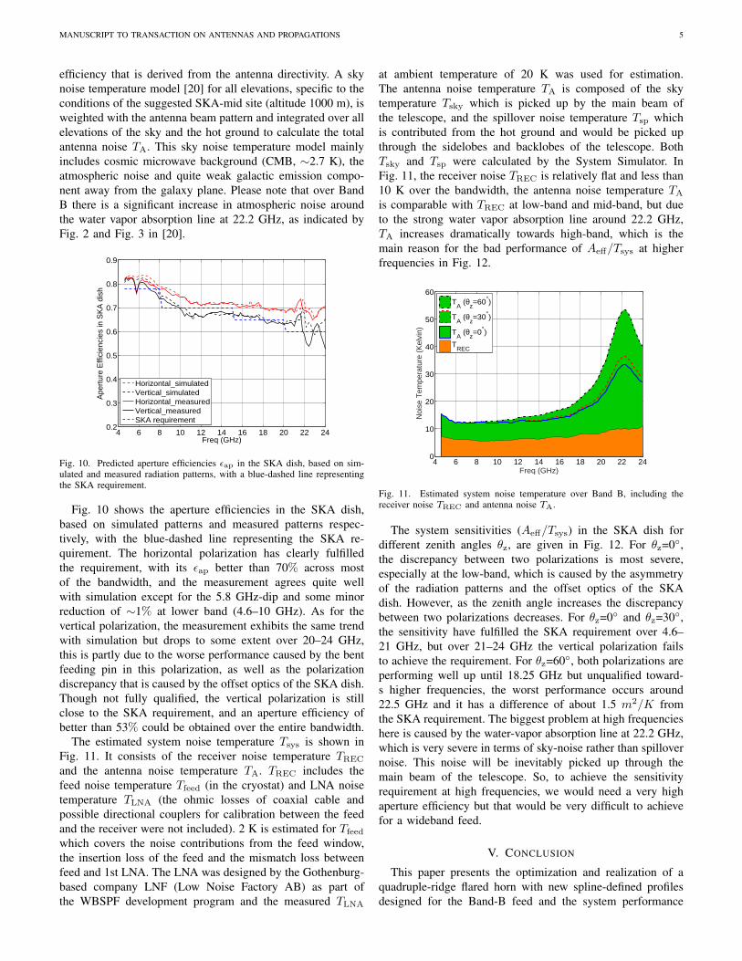
The estimated system noise temperature Tsys is shown inFig. 11. It consists of the receiver noise temperature TREC
and the antenna noise temperature TA. TREC includes thefeed noise temperature Tfeed (in the cryostat) and LNA noisetemperature TLNA (the ohmic losses of coaxial cable andpossible directional couplers for calibration between the feedand the receiver were not included). 2 K is estimated for Tfeed
which covers the noise contributions from the feed window,the insertion loss of the feed and the mismatch loss betweenfeed and 1st LNA. The LNA was designed by the Gothenburg-based company LNF (Low Noise Factory AB) as part ofthe WBSPF development program and the measured TLNA
at ambient temperature of 20 K was used for estimation.The antenna noise temperature TA is composed of the skytemperature Tsky which is picked up by the main beam ofthe telescope, and the spillover noise temperature Tsp whichis contributed from the hot ground and would be picked upthrough the sidelobes and backlobes of the telescope. BothTsky and Tsp were calculated by the System Simulator. InFig. 11, the receiver noise TREC is relatively flat and less than10 K over the bandwidth, the antenna noise temperature TA
is comparable with TREC at low-band and mid-band, but dueto the strong water vapor absorption line around 22.2 GHz,TA increases dramatically towards high-band, which is themain reason for the bad performance of Aeff/Tsys at higherfrequencies in Fig. 12.
4 6 8 10 12 14 16 18 20 22 240
10
20
30
40
50
60
Freq (GHz)
Noi
se T
empe
ratu
re (
Kel
vin)
TA (θ
z=60°)
TA (θ
z=30°)
TA (θ
z=0°)
TREC
Fig. 11. Estimated system noise temperature over Band B, including thereceiver noise TREC and antenna noise TA.
The system sensitivities (Aeff/Tsys) in the SKA dish fordifferent zenith angles θz, are given in Fig. 12. For θz=0,the discrepancy between two polarizations is most severe,especially at the low-band, which is caused by the asymmetryof the radiation patterns and the offset optics of the SKAdish. However, as the zenith angle increases the discrepancybetween two polarizations decreases. For θz=0 and θz=30,the sensitivity have fulfilled the SKA requirement over 4.6–21 GHz, but over 21–24 GHz the vertical polarization failsto achieve the requirement. For θz=60, both polarizations areperforming well up until 18.25 GHz but unqualified toward-s higher frequencies, the worst performance occurs around22.5 GHz and it has a difference of about 1.5 m2/K fromthe SKA requirement. The biggest problem at high frequencieshere is caused by the water-vapor absorption line at 22.2 GHz,which is very severe in terms of sky-noise rather than spillovernoise. This noise will be inevitably picked up through themain beam of the telescope. So, to achieve the sensitivityrequirement at high frequencies, we would need a very highaperture efficiency but that would be very difficult to achievefor a wideband feed.
V. CONCLUSION
This paper presents the optimization and realization of aquadruple-ridge flared horn with new spline-defined profilesdesigned for the Band-B feed and the system performance
MANUSCRIPT TO TRANSACTION ON ANTENNAS AND PROPAGATIONS 6
4 6 8 10 12 14 16 18 20 22 240
2
4
6
8
10
12
14
Freq (GHz)
Aef
f / T sy
s (m
2 /K)
HorizontalVerticalSKA requirement
(a)
4 6 8 10 12 14 16 18 20 22 240
2
4
6
8
10
12
14
Freq (GHz)
Aef
f / T sy
s (m
2 /K)
HorizontalVerticalSKA requirement
(b)
4 6 8 10 12 14 16 18 20 22 240
2
4
6
8
10
12
14
Freq (GHz)
Aef
f / T sy
s (m
2 /K)
HorizontalVerticalSKA requirement
(c)
Fig. 12. Predicted system sensitivities of both polarizations for different zenith angle: (a) θz=0; (b) θz=30 and (c) θz=60.
analysis in the SKA dish. The feed exhibits a good impedancematching and beam performance over more than 5:1 band-width. Its sub-efficiencies and radiation patterns show thatby adopting spline-defined profiles, more constant beamwidthand more symmetrical radiation patterns have been obtained,hence improved ϵBOR1 , ϵpol and ϵill · ϵsp can be achieved.An edge-extrude mechanical technique was implemented torealize a good contact between ridges and horn sidewall,so as to guarantee a high operational frequency. Measuredresults show reasonable agreement with simulations, predictedaperture efficiency in the SKA dish based on the measuredfarfield patterns have fulfilled the SKA requirement for itshorizontal polarization, with a polarization discrepancy thatmakes the vertical polarization unqualified over part of thebandwidth. This discrepancy is caused by the asymmetricaloptics of the SKA offset dish which are not fully optical-matched with the symmetrically-designed Band-B feed, andthus was ignored during our primary-fed-parabolic optimiza-tion. As for the predicted Aeff/Tsys, a large margin above therequirement over low- and mid-band was achieved, while athigh-band it slightly fails to satisfy the requirement due to thestrong water-vapor absorption line around 22.2 GHz.
ACKNOWLEDGMENT
The authors would like to thank Heka Mechanical Engineer-ing AB and Jocke at Micro-Slip HB for their valuable advicesduring the manufacture, and Jose Manuel Serna Puente, Dr.Jose Antonio Lopez Fernandez and Samuel Lopez Ruiz fromYebes Observatory for their efforts on the pattern measure-ment.
REFERENCES
[1] R. Taylor, “The SKA: Recent developments,” in 2015 Radio and AntennaDays of the Indian Ocean (RADIO), Sept 2015, pp. 1–2.
[2] M. Garrett, J. Cordes, D. Deboer, J. Jonas, S. Rawlings, and R. Schilizzi,“Square Kilometre Array: a concept design for Phase 1,” arXiv preprintarXiv:1008.2871, 2010.
[3] J. Yang, M. Pantaleev, P.-S. Kildal, B. Klein, Y. Karandikar, L. Helldner,N. Wadefalk, and C. Beaudoin, “Cryogenic 2–13 GHz Eleven feed forreflector antennas in future wideband radio telescopes,” IEEE Trans.Antennas Propag., vol. 59, no. 6, pp. 1918–1934, 2011.
[4] J. Yang, M. Pantaleev, B. Billade, M. Ivashina, T. Carozzi, L. Helldner,and M. Dahlgren, “A Compact Dual-Polarized 4-Port Eleven Feed WithHigh Sensitivity for Reflectors Over 0.35–1.05 GHz,” IEEE Trans.Antennas Propag., vol. 63, no. 12, pp. 5955–5960, Dec 2015.
[5] A. Akgiray, S. Weinreb, and W. Imbriale, “Design and measurementsof dual-polarized wideband constant-beamwidth quadruple-ridged flaredhorn,” in IEEE Int. Symp. Antennas Propag., July 2011, pp. 1135–1138.
[6] A. Akgiray and S. Weinreb, “Ultrawideband square and circular quad-ridge horns with near-constant beamwidth,” in IEEE Int. Conf. Ultra-Wideband. IEEE, 2012, pp. 518–522.
[7] A. Akgiray, S. Weinreb, W. A. Imbriale, and C. Beaudoin, “Circularquadruple-ridged flared horn achieving near-constant beamwidth overmultioctave bandwidth: Design and measurements,” IEEE Trans. Anten-nas Propag., vol. 61, no. 3, pp. 1099–1108, 2013.
[8] O. B. Jacobs, J. W. Odendaal, and J. Joubert, “Elliptically shaped quad-ridge horn antennas as feed for a reflector,” IEEE Antennas WirelessPropag. Lett., vol. 10, pp. 756–759, 2011.
[9] T. S. Beukman, M. V. Ivashina, R. Maaskant, P. Meyer, and C. Ben-civenni, “A quadraxial feed for ultra-wide bandwidth quadruple-ridgedflared horn antennas,” in 8th Eur. Conf. Antennas Propag.(EuCAP 2014),2014, pp. 3312–3316.
[10] R. Lehmensiek, I. P. Theron, and D. I. L. de Villiers, “Deriving an op-timum mapping function for the ska-shaped offset gregorian reflectors,”IEEE Trans. Antennas Propag., vol. 63, no. 11, pp. 4658–4666, Nov2015.
[11] D. I. L. de Villiers and R. Lehmensiek, “Dual reflector shaping forrealistic frequency dependent feed patterns with specific secondary fieldpattern targets,” in 8th Eur. Conf. Antennas Propag.(EuCAP 2014), April2014, pp. 13–17.
[12] T. S. Beukman, P. Meyer, M. V. Ivashina, and R. Maaskant, “Modal-Based Design of a Wideband Quadruple-Ridged Flared Horn Antenna,”IEEE Trans. Antennas Propag., vol. 64, no. 5, pp. 1615–1626, May2016.
[13] J. Shi, S. Weinreb, W. Zhong, X. Yin, and M. Yang, “Quadruple-ridgedflared horn operating from 8 to 50 ghz,” IEEE Transactions on Antennasand Propagation, vol. 65, no. 12, pp. 7322–7327, Dec 2017.
[14] B. Billade, J. Flygare, M. Dahlgren, M. Pantaleev et al., “A wide-band feed system for SKA Band 1 covering frequencies from 350–1050MHz,” in 10th Eur. Conf. Antennas Propag.(EuCAP 2016). IEEE, 2016,pp. 1–3.
[15] J. Yang, J. Flygare, M. Pantaleev, and B. Billade, “Development ofquadruple-ridge flared horn with spline-defined profile for band B ofthe Wide Band Single Pixel Feed (WBSPF) advanced instrumentationprogramme for SKA,” in IEEE Int. Symp. Antennas Propag., June 2016,pp. 1345–1346.
[16] A. Akgiray, “New Technologies Decade-Bandwidth Radio Astronomy:Quad-Ridged Flared Horn & Compound-Semiconductor LNAs,” Ph.DThesis, California Institute of Technology, Pasadena, California, 2013.
[17] P. S. Kildal and Z. Sipus, “Classification of Rotationally SymmetricAntennas as Types BOR0 and BOR1,” IEEE Antennas Propag. Mag.,vol. 37, no. 6, pp. 114–117, Dec. 1995.
[18] P.-S. Kildal, Foundations of Antenna Engineering: A Unified Approachfor Line-of-Sight and Multipath. Artech House, 2015.
[19] M. V. Ivashina, O. Iupikov, R. Maaskant, W. A. van Cappellen, andT. Oosterloo, “An Optimal Beamforming Strategy for Wide-Field Sur-veys With Phased-Array-Fed Reflector Antennas,” IEEE Trans. AntennasPropag., vol. 59, no. 6, pp. 1864–1875, June 2011.
[20] G. Cortes-Medellin, “Antenna Noise Temperature Calculations,” SKAMemo 95, July 2007.