INFORMATICA, 1994, Vol. 5, No. 3-4,439-451 OPTIMIZATION ASPECTS RELATIVELY TO PLACEMENT OF COMPONENTS OF GATE ARRAY VLSI Vilius ZILEVICIUS and Alfonsas MISEVICIUS Kaunas University of Technology 3028 Kaunas, Studentq St. 50-401, Lithuania Abstract. In this paper optimization aspects relatively to circuit component placement problem for gate array VLSI are discussed. Practical and theoretical aspects of the methods of component placement are concerned as well. Effective heuristic algorithms for the initial placement and iterative placement improvement are described. An original strategy of global placement optimization is investigated. Some experimental results based on an automatic placement subsystem for gate arrays - AUTO PLACE developed at Department of Practical Informatics of Kaunas University of Technology are presented. Key words: CAD, VLSI, placement, optimization. 1. Introduction. One of the most important problems in computer aided design (CAD) system for very large scale integration (VLSI) is layout design. It involves several distinct subproblems: chip planning, partitioning, placement of circuit components and {outing of wires for in- terconnected components; This paper investigates one of the key problems - placement problem - the assignment of circuit's elements to locations on the chip (master-slice). The main goal of the placement is to arrange the components on the slots in such a way, that the selected criteria of "routability" are optimized while satisfying electrical constraints. Neces- sary and sufficient conditions for the wire routing must be created. The placement problem is a complex problem to solve it exactly for large gate arrays (Odawara et aI., 1987). Therefore heuristic solutions are applied. The hard problem is broken into a cascade of simpler ones;
Transcript
INFORMATICA, 1994, Vol. 5, No. 3-4,439-451
OPTIMIZATION ASPECTS RELATIVELY TO PLACEMENT OF COMPONENTS
OF GATE ARRAY VLSI
Vilius ZILEVICIUS and Alfonsas MISEVICIUS
Kaunas University of Technology 3028 Kaunas, Studentq St. 50-401, Lithuania
Abstract. In this paper optimization aspects relatively to circuit component
placement problem for gate array VLSI are discussed. Practical and theoretical
aspects of the methods of component placement are concerned as well. Effective
heuristic algorithms for the initial placement and iterative placement improvement are described. An original strategy of global placement optimization is investigated.
Some experimental results based on an automatic placement subsystem for gate
arrays - AUTO PLACE developed at Department of Practical Informatics of Kaunas
University of Technology are presented.
Key words: CAD, VLSI, placement, optimization.
1. Introduction. One of the most important problems in computer
aided design (CAD) system for very large scale integration (VLSI) is layout design. It involves several distinct subproblems: chip planning,
partitioning, placement of circuit components and {outing of wires for in
terconnected components; This paper investigates one of the key problems
- placement problem - the assignment of circuit's elements to locations
on the chip (master-slice). The main goal of the placement is to arrange
the components on the slots in such a way, that the selected criteria of
"routability" are optimized while satisfying electrical constraints. Neces
sary and sufficient conditions for the wire routing must be created.
The placement problem is a complex problem to solve it exactly for
large gate arrays (Odawara et aI., 1987). Therefore heuristic solutions are applied. The hard problem is broken into a cascade of simpler ones;
440 Optimization aspects
the whole placement is decomposed into several distinct steps. Classical
placement scheme, according to Brady and Blanks (1987), consists of \wo main steps:, 1) initial placement and 2) iterative, replacement. Hierarcllical approaches are widely used. We introduce an Oljginal placement
optimization scheme, which includes the steps above and, additionally, placement optimization phase. Global optimization has been used for cell placement and partitions (Ding et al., 1993). We apply global optimization techniques to gate array placement. Corresponding algorithms are discussed on basis of the experimental placement subsystem AUTOPLACE for the fully automated placement of VLSI components Cnlevi~ius and Misevi~ius, 1992).
2. Placement model for VLSIon gate arrays
2.1. Practical aspects of placement on gate arrays. In the semicustom gate array approach, fixed geometry and regular structure of a basic chip are distinctive. The core cells (slots) are organized as a matrix of rows and columns on the gate array master-slice. They form the central regular part of the master-slice. Input/output peripheral cells are located around. The areas between slots are for routing (Fig. 1).
-' -----+--~---oDD D DID D D D ~°:;-!f-_7 routing area
~ D 0 0 '0 I 0 0 0 D 0
000000000 I 000000000
I Fig. 1. Gate array initial layout.
V. Zilevicius and A. Misevicius 441
Basic circuit elements containing logical gates are designed by circuit designer prior to placement and saved in the element library. They form circuit functional layout units (components) to perform certain logic functions. These functional components have to be assigned to the predefined slots on the master-slice.
Both functional components in the central part and peripheral elements in the va cells can be placed using fully automated placement subsystem. The circuit components of different types and shapes and the fixed (pre-assigned) components are taken into consideration.
2.2. Automatic placement and optimization model
The placement problem. The placement problem can be formulated in the following manner: a set of n components or elements E = { e1, e2, ... , en} is to be optimally assigned to a set of m locations or slots S = {81' 82, ... ,8m }. The optimality is measured in terms of the expected "routability" of the placement. A universal measure - the objective function to be minimized - is introduced:
n-1 n m m
F= L L LLXik·Xjr·qij"lkr,
i=l j=i+1 k=l r=l
m n
where 2: Xik = 1, i = 1, n; 2: Xik ~ 1, k = 1, m; n ~ m; k=l i=l
{ I, if element e i is assigned to a slot 8 k ; Xjk =
0, otherwise;
(1)
qij - the number of interconnections between components ej
and ej;
lkr - the distance between slots 8k and 8 r .
Because of the very complexity of optimization of the function F, approximate objective functions are investigated. Those are described in paragraph 2.4.
The placement model. In practicable applications, solving of the place· ment problem is performed in two main steps: 1) initial placement and/or
442 Optimization aspects
2) iterative replacement. A heuristic constructive algorithm for the initial placement and the iterative algorithms for the placement improvement (replacement) are applied. Placement optimizing criteria (objective functions) correlated with "routability" (for example, estimates of interconnection length and wire congestion) are selected in order to predict routing success. We consider, namely: 1) total estimated (weighted) wire length (quadratic objective function); 2) total estimated wire congestion (min-cut objective function).
Key concept of the presented placement model is the global placement optimization based on the above objective functions.
The general flow of the automatic placement subsystem is as follows:
Circuit specifications
• INITIAL PLACEMENT
• INITIAL REPLACEMENT
• GLOBAL PLACEMENT OPTIMIZATION
• FINAL PLACEMENT EDITION Layout data base.
2.3. Initial placement. The initial placement is based on the conventional constructive algorithm in combination with the special return (restart) procedure (Abraitis and Tomkevicius, 1987). The prior placed (pre-assigned) components are taken into account, that is, fixed components are initially considered to be "already placed". Then, until all components have been placed, the placement configuration is being formed by operating upon the set of unplaced components, selecting one of them and positioning in the free cell. The algorithm finds the component ei -
most connected to those components "already placed". The "most connected component" is the unplaced component having the highest sum of interconnection weights to the "already placed" components. The "best suitable position" Sk for the chosen component is the unoccupied one, which is selected in such a way, that the heuristic hik for the component ei is minimized. The heuristic hik is defined as follows:
(2)
V. Zilevicius and A. Misevicius 443
a) bloci{ed situation b) placement return/correction c) newplacet,nent configuration
00 0
00 0
00 00 -. [,] 0" .... 1 .. ····0
t current
component
00 O-
00 0-
00 DD
:'"0 ~o
00 00 00 00
00 00
o - components already placed
Fig. 2. Placement with return.
where qkp - number of connections with already placed component(s) in position 8 k ,
qp - number of connections with components placed in the same row or column just as position 8 k,
qu - number of connections with unplaced components, lp - total length of connections with placed components,
0.05, ... ,1). Presented heuristic and experimental weight coefficients seem to be
a good way to achieve sufficient expected initial wire length as well as congestion.
In case of an unsuccessful placing of the current component, the return procedure makes an attempt to get the new placement configuration in order to overcome the blocked (deadlock) situation, that is, to vacate the position for the candidate component (Fig. 2). When necessary, the restart procedure starts all the placement with quiet new initial conditions. In case of any existing pre-defined placement, initial placement phase can be omitted.
The produced placement is necessary to be improved using the iterative replacement steps described below.
2.4. Initial replacement. At this step an iterative improvement of the initial placement configuration is provided. The initial replacement
444 Optimization aspects
aims at optimizing the cost criterion based on the predictive wire length or congestion. Iterative replacement algorithms and techniques, like pairwise/group interchanges or min-cut replacement, have been applied.
A. Pairwise interchanges. In case of the pairwise interchanges, convex quadratic objective function is introduced (Brady and Blanks, 1987). The expected wire length to be minimized is calculated as the sum of squared distances between all the pairs of net points to be connected. The function to be minimized is described as follows:
where qij - the weight factor, i.e., number of interconnections between components ej ande j;
Xi, Yi, x j, Y j - the co-ordinates of the locating points of the components ei and e j.
The wire length minimization is performing by permitting pairwise interchanges of all the selected single components. A new component's position is accepted if the total wire length is decreased only.
Simulated annealing techniques (Kirkpatrick et al., 1983) relatively to pairwise interchanges may be optionally applied for the initial placement optimization.
B. Min-cut replacement. In case of the min-cut replacement vertical and horizontal cutlines are selected (Breuer, 1977a; 1977b). They partition chip surface into many rectangular areas/sections (Fig. 3). The number of wires crossing a certain cutline is called the degree of that cutline. The single components or groups of ones are interchanged in order to minimize the total summary degree of all the horizontal and vertical cutlines (segments). For that reason, techniques similar to pairwise interchanges, as well as group interchange and shifting techniques are applied (Zilevicius and Baltrusaitis, 1985). We introduce the following min-cut objective function:
lUI IVI
Fe = L U ; + LV;, (4) i=l j=l
v. Zilevicius and A. Misevicius
0 0 0 0 0
0 0
0 • 0 0 0 0
Fig. 3. Cut segments.
where U - the set of the horizontal cutlines,
V - the set of the vertical cutlines,
Ui( Vj) - the degree of the cutline - i(j).
0
445
_ horizontal cutlines
crossIng wIres
_ vertical clltline
the components in the slots
A modified min-cut replacement algorithm is used for the wire congestion optimization. The algorithm consists of the following steps:
1. select one of the cutlines;
2. find two components (or block of components) from the opposite sides of the selected cutline;
3. try to place these components on the opposite side;
4. accept new component position if value of the cost function is
decreased;
5. repeat steps 1-4 until all the cutlines are selected.
2.5. Global placement optimization. It was observed, that minimizing wire length alone is not sufficient to achieve the global minimum of the objective function and construct a "routeable" circuit layout design. Therefore, a combination of various replacement algorithms (techniques)
446 Optimization aspects
r-----------·------ .. -----) I) Minimization of the total wire length
~ II) Optimization of the wire congestion
1) Main phase of the congestion optimization .-
Global optimization iteration ,-- ---
Local optimization iteration
r- ~ Min-cut replacement
~up interchanges of the components Pairwise interchanges of the components
2) Final phase of the congestion optimization I I L _____ .
Fig. 4. Global replacement.
and progressive switching over to more measures in an objective function have been analysed.
An original strategy of the global optimization of the placement configuration is investigated. The global replacement (optimization) is based on two recursive iterative phases: a) the wire length minimization (I-replacement) and b) the wiring area congestion optimization (IIreplacement). Quadratic objective function FL and min-cut objective function Fe is minimized in the recursive way; however convexit;y of the
V. Zilevicius and A. Misevicius 447
2 1 3
• - free track for routing
• • • • • • • - pins of the component
• • • 4 3 4 2
1) # of free tracl{s = 0 2) # of free tracks = 1 (variant 1324)
Fig. S. Optimization of the placement by mirroring/rotating.
objective functions is disturbed (Fig. 6B). Therefore, a complex objective function (Z) is introduced:
where FL, Fe - functions described in paragraph 2.4; WI, W2 - weight/normalization factors.
(5)
While selecting corresponding numbers of iterations for I-replacement and II-replacement and weight coefficients, placement optimization process may be controlled. Fig. 4 illustrates the iterations of the global placement optimization.
The reason of this methodology is that wire length minimization and min-cut replacement is iteratively repeated in order to converge to possible suboptimal solution. This strategy seems to be very effective way to get out of local optimum regions, and then continue further optimization processes successfully. On basis of the experimental results we conclude that above global replacement algorithm can yield sufficient results for any initial placement.
2.6. Final placement edition. The final replacement improvement procedure is implemented in order to increase a number of free paths for the wire routing at the cell internal areas. Rotating and mirroring of the single components at their gate array positions have been introduced to optimize the configuration of signal pins (paths) of the components
448 Optimization aspects
(Fig. 5). This is helpful way to avoid local blocked situations for the wire routing in overloaded areas.
In addition, the final results may be improved using above scheme of the automatic placement repeatedly in combination with an interactive/manual placement editing tools.
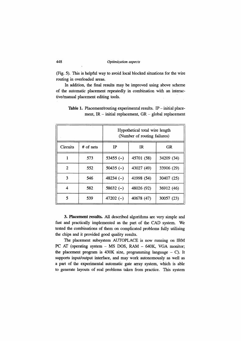
Table 1. Placement/routing experimental results. IP - initial placement, IR - initial replacement, GR - global replacement
Hypothetical total wire length (Number of routing failures)
Circuits # of nets IP IR GR
1 573 53455 (-) 45701 (58) 34209 (34)
2 552 50435 (-) 43027 (49) 33906 (29)
3 546 48234 (-) 41998 (54) 30407 (25)
4 582 58632 (-) 48026 (92) 36912 (46)
5 539 47202 (-) 40678 (47) 30057 (23)
3. Placement results. All described algorithms are very simple and fast and practically implemented as the part of the CAD system. We tested the combinations of them on complicated problems fully utilising the chips and it provided good quality results.
The placement subsystem AUTOPLACE is now running on IBM PC AT (operating system - MS DOS, RAM - 640K, VGA monitor; the placement program is 430K size, programming language - C). It supports input/output interface, and may work autonomously as well as a part of the experimental automatic gate array system, which is able to generate layouts of real problems taken from practice. This system
has been employed for VLSI manufacturing. Adaptability, flexibility,
integrity, as well as original and effective algorithms - are main features of the subsystem AUTO PLACE. The necessary userfriend graphic interface
with a designer is also supported. AUTOPLACE is able to provide fully automatic placement up to
500 functional components (5000 logic gates). Many chips (85%-95% utilised) having 150-200 cells with about 200 to 300 components were processed using this system. Some of the experimental results are illustrated in the Fig. 6 and Table 1.
REFERENCES
Abraitis, L., and A.TomkeviCius (1987). Operational scheme of the placement of components of gate array chips. Upravl. Sisto i Mash., 4, 27-32 (in Russian).
Brady, N.H., and J.Blanks (1987). Automatic placement and routing techniques
for gate array and standard cell designs. Proceedings of the IEEE, 75(6), 797-806.
Breuer, M.A. (1977a). A class of min-cut placement algorithms. 14th ACM-IEEE Design Automation Conj, 284-290.
Breuer, M.A. (1977b). Min-cut placement. J. Design Automation and FaultTolerant Computing, 1, 343-362.
Ding, Ch.L., Ch.Y. Ho and M.J.Irwin (1993). A new optimization driven clustering algorithm for large circuits. 0-818~350-1193 $3.00 1993 IEEE, 28-32.
Kirkpatrick, S., C.D.Gelatt, Jr. and M.P.Vecchi (1983). Optimization by simulated
annealing. Science, 220(4598), 671-680.
Odawara, G., T.Hiraide and O.Nishina (1987). Partitioning and placement tech
nique for CMOS gate arrays. 0278-007018710500-0355 $01.001987 IEEE, 355-363.
Zilevicius, V., and R.Baltrubitis (1985). Criteria of the uniform placement.
Avtomatizatsya kOllstruktorskogo proektirovanya v radioelektronike i vychislitel'noj technike, 5, 26-43 (in Russian).
Zilevicius, V., and A. MiseviCius (1992). An automatic placement lor LSI layout.
V. Zilevicius Or. techn., currently associate professor at Practical Informatics Department, Faculty of Informatics, Kaunas University of Technology. The main areas of interest are computer graphics, spatial data management and optimization problems related to CAD and Geographical Information Systems.
A. Misevicius was born in 1962. He received the Dipl. Eng. degree from Kaunas Polytechnic Institute, Lithuania, in 1986. From 1986 to 1991 he worked as a junior research fellow at Computer Research Laboratory, Kaunas Polytechnic Institute. Now he is a post-graduate student at Kaunas University of Technology. His research interests include CAD, VLSI layout design, engineering information systems.