OPTIMIZATION OF AUTOMATIC IMAGE REGISTRATION ALGORITHMS AND CHARACTERIZATION Ch.Venkateswara Rao a , Dr. K.M.M.Rao a , A.S.Manjunath a , R.V.N.Srinivas b a National Remote Sensing Agency, Hyderabad(rao_cv, rao_kmm, manjunath_as )@nrsa.gov.in b M.Tech project student from BIT-Mesra, Ranchi ([email protected]) PS Comission III,WG,III/8 KEY WORDS: Remote Sensing, Geometry, Medicine, Registration, Automation, Accuracy. ABSTRACT: In many image-processing applications it is necessary to register multiple images of the same scene acquired by different sensors, or images taken by the same sensor but at different times. Mathematical modeling techniques are used to correct the geometric errors like translation, scaling and rotation of the input image to that of the reference image, so that these images can be used in various applications like change detection, image fusion etc. In the conventional methods, these errors are corrected by taking control points over the image and these points are used to establish the mathematical model. The objective of this paper is to implement and evaluate a set of automatic registration algorithms to correct the geometric errors of the input image with respect to the reference image, by increasing the accuracy level of the registration and reducing the RMS error to less than a pixel. Various algorithms such as Wavelet transformation method, Fast Fourier transformation method, Morphological Pyramid approach and Genetic Algorithms are developed and compared. These algorithms are capable of considering the transformation model to sub-pixel accuracy. The benefits of these methods are accuracy, stability of estimation, automated solution and the low computational cost. 1. INTRODUCTION Image registration is one of the basic image processing operations in remote sensing. By registering the two different images acquired during different times or by different sensors can be used in various applications like change detection, image fusion (A.S.Kumar, 2003) etc. Most of image registration approaches fall into local or global methods. Local methods are referred to as rubber sheeting or the control-points method. Global methods involve finding a single transformation imposed on the whole image and are also referred to as automatic registration methods. Registration methods (L.G.Brown, 1992), can be viewed as different combinations of choices for the following four components: (1) Feature space (2) Search space (3) Search strategy and (4) Similarity metric. The Feature space extracts the information in the images that will be used for matching. The Search space is the class of transformations that is capable of aligning the images. The Search strategy decides how to choose the next transformation from this space, to be tested in the search for the optimal transformation. The Similarity metric determines the relative merit for each test. Search continues according to the search strategy until a transformation is found whose similarity measure is satisfactory. The types of variations present in the images will determine the selection for each of these components. For example, the problem of registering two images taken of the same place at different times can be considered. Assuming that the primary difference in acquisition of the images was a small translation of the scanner, the search space might be a set of small translations. For each translation of the edges of the left image onto the edges of the right image, a measure of similarity would be computed. A typical similarity measure would be the correlation between the images. If the similarity measure is computed for all translations then the search strategy is simply exhaustive. The images are registered using the translation, which optimizes the similarity criterion. However, the choice of using edges for features, translations for the search space, exhaustive search for the search strategy and correlation for the similarity metric will influence the outcome of this registration. In general all the image registration techniques evaluated during this study, were based on local methods that required manual selection of ground control points (GCPs) over the image and these points are used to establish the mathematical model .The selection of these control points is subjective and can lead to inconsistencies as it is interactive with the operator. The objective of this paper is to characterise a set of automatic registration algorithms to correct the geometric errors of the input image with respect to the reference image, by increasing the accuracy level of the registration and reducing the RMS error to less than a pixel. In the next section, we have provided a brief overview of some of the related work in this area. Sections 3 and 4 describe the methodology followed by the experimental results obtained on some common data sets. Lastly we have also provided some comparative measures on efficiency of various parameters between the different algorithms evaluated. 2.AUTOMATIC REGISTRATION METHODS The image registration process is usually carried out in three steps (Leila M. Fonesca, 1997). The first step consists of selection of features. In the next step each of these features are compared with potential corresponding features of the other image. A pair of matched features is accepted as a control point (CP). Finally using these CPs a transformation is established to model the deformation between the images. To carry out this process automatically several algorithms have been proposed and were divided into the following classes (B.S.Reddy, 1996). (1) Algorithms that directly use image pixel values (2) Algorithms that operate in the frequency domain (3) Algorithms that use low-level features such as edges and corners and (4) Algorithms that use high-level features such as identified objects, or features. After studying various algorithms the following four methods
Transcript
OPTIMIZATION OF AUTOMATIC IMAGE REGISTRATION ALGORITHMSAND CHARACTERIZATION
Ch.Venkateswara Rao a, Dr. K.M.M.Rao a, A.S.Manjunath a, R.V.N.Srinivas b
a National Remote Sensing Agency, Hyderabad(rao_cv, rao_kmm, manjunath_as )@nrsa.gov.inb M.Tech project student from BIT-Mesra, Ranchi ([email protected])
In many image-processing applications it is necessary to register multiple images of the same scene acquired by different sensors, orimages taken by the same sensor but at different times. Mathematical modeling techniques are used to correct the geometric errorslike translation, scaling and rotation of the input image to that of the reference image, so that these images can be used in variousapplications like change detection, image fusion etc. In the conventional methods, these errors are corrected by taking control pointsover the image and these points are used to establish the mathematical model. The objective of this paper is to implement andevaluate a set of automatic registration algorithms to correct the geometric errors of the input image with respect to the referenceimage, by increasing the accuracy level of the registration and reducing the RMS error to less than a pixel. Various algorithms suchas Wavelet transformation method, Fast Fourier transformation method, Morphological Pyramid approach and Genetic Algorithmsare developed and compared. These algorithms are capable of considering the transformation model to sub-pixel accuracy. Thebenefits of these methods are accuracy, stability of estimation, automated solution and the low computational cost.
1. INTRODUCTION
Image registration is one of the basic image processingoperations in remote sensing. By registering the two differentimages acquired during different times or by different sensorscan be used in various applications like change detection,image fusion (A.S.Kumar, 2003) etc. Most of imageregistration approaches fall into local or global methods. Localmethods are referred to as rubber sheeting or the control-pointsmethod. Global methods involve finding a singletransformation imposed on the whole image and are alsoreferred to as automatic registration methods. Registrationmethods (L.G.Brown, 1992), can be viewed as differentcombinations of choices for the following four components:
The Feature space extracts the information in the images thatwill be used for matching. The Search space is the class oftransformations that is capable of aligning the images. TheSearch strategy decides how to choose the next transformationfrom this space, to be tested in the search for the optimaltransformation. The Similarity metric determines the relativemerit for each test. Search continues according to the searchstrategy until a transformation is found whose similaritymeasure is satisfactory. The types of variations present in theimages will determine the selection for each of thesecomponents. For example, the problem of registering two images taken of thesame place at different times can be considered. Assuming thatthe primary difference in acquisition of the images was a smalltranslation of the scanner, the search space might be a set ofsmall translations. For each translation of the edges of the leftimage onto the edges of the right image, a measure of similaritywould be computed. A typical similarity measure would be thecorrelation between the images. If the similarity measure iscomputed for all translations then the search strategy is simplyexhaustive. The images are registered using the translation,
which optimizes the similarity criterion. However, the choice ofusing edges for features, translations for the search space,exhaustive search for the search strategy and correlation for thesimilarity metric will influence the outcome of this registration. In general all the image registration techniques evaluated duringthis study, were based on local methods that required manualselection of ground control points (GCPs) over the image andthese points are used to establish the mathematical model .Theselection of these control points is subjective and can lead toinconsistencies as it is interactive with the operator. Theobjective of this paper is to characterise a set of automaticregistration algorithms to correct the geometric errors of theinput image with respect to the reference image, by increasingthe accuracy level of the registration and reducing the RMSerror to less than a pixel.In the next section, we have provided a brief overview of someof the related work in this area. Sections 3 and 4 describe themethodology followed by the experimental results obtained onsome common data sets. Lastly we have also provided somecomparative measures on efficiency of various parametersbetween the different algorithms evaluated.
2.AUTOMATIC REGISTRATION METHODS
The image registration process is usually carried out in threesteps (Leila M. Fonesca, 1997). The first step consists ofselection of features. In the next step each of these features arecompared with potential corresponding features of the otherimage. A pair of matched features is accepted as a control point(CP). Finally using these CPs a transformation is established tomodel the deformation between the images. To carry out thisprocess automatically several algorithms have been proposedand were divided into the following classes (B.S.Reddy, 1996).
(1) Algorithms that directly use image pixel values (2) Algorithms that operate in the frequency domain (3) Algorithms that use low-level features such as edgesand corners and(4) Algorithms that use high-level features such asidentified objects, or features.
After studying various algorithms the following four methods
were identified to cover, one from each class.Wavelet-Modulus Maxima method (Leila M. Fonesca, 1997),uses image pixel values, similar to that described in (Q. Zheng,1993) except determining the feature selection. The probablecontrol points are detected from the local modulus maxima ofthe wavelet transform, applied to the input and referenceimages, after performing the wavelet decomposition up to twolevels. The correlation coefficient is used as a similaritymeasure and only the best pair-wise fitting, among all pairs offeature points, are taken as actual control points. A polynomialtransform, which can take care of translation and rotationalerrors, is then used to model the deformation between theimages and their parameters are estimated in a coarse to finemanner. The refinement matching is achieved using the warpedimage and the set of feature points detected in the referenceimage. After processing all levels the final parameters aredetermined and used to warp the original input image.Fast Fourier Transform (FFT) technique (B.S.Reddy, 1996,Y.Keller, 2002) is a frequency domain approach in which itdoes not use any control points, instead the FFT ratio iscomputed. The displacement between two given images can bedetermined by computing the ratio F1.conj(F2)/|F1.F2|, theinverse of this ratio results as an impulse like function. This isapproximately zero everywhere except at the displacement, thisdetermines the translation error between the images. Convertingthese images from rectangular coordinates to log-polarcoordinates and by calculating the similar ratio, we canrepresent rotation and scaling errors also as shifts. These threeparameters are used to establish the mathematical model andthe image is geometrically rectified with respect to thereference image. Morphological Pyramid Image Registration algorithm(Zhongxiu HU, 2000) uses the low level shape features todetermine the global affine transformation model along with theradiometric changes between the images. The multi resolutionimages are represented by a Morphological Pyramid (MP), asthe MP’s have the capability to eliminate details and tomaintain shape features. The Levenberg Marquardt non-linearoptimization algorithm is employed to estimate the matchingparameters of translation, rotation and scaling errors up to subpixel accuracy. In this approach intensity mapping function isintegrated into geometric mapping function.
Image Registration using Genetic Algorithms (GAs) (J.H.Holland, 1975) uses the comparison of identified solutions toensure a population’s survival under changing environmentalconditions. GAs are iterative procedures that maintain apopulation of candidate solutions encoded in the form ofchromosome strings. The initial population can be generatedrandomly. These candidates will be selected using a selectioncriterion for the reproduction in the next generation based ontheir fitness values. GAs search is used to efficiently explorethe huge solution space required by the image registration to asub pixel accuracy.
3. METHODOLOGY
Mathematical modeling techniques are used to correct thegeometric errors like translation, rotation and scaling of theinput image to that of the reference image. Let the image to bewarped be called the input image and to which it is reduced iscalled the reference image. There are two cases to consider forthe image registration algorithms: a) The images have the same ground resolution (pixel size) b) The images are taken from different sensors and havedifferent ground resolutions.Each of the above algorithms models the same deformation in
its own way. The input image needs to be interpolated whilewarping. The simplest scheme for gray-level interpolation isbased on the nearest neighbor approach called zero-orderinterpolation. But the nearest neighbor interpolation yieldsundesirable artifacts such as stair-stepped effect arounddiagonal lines and the curves. Bilinear interpolation producesthe output images that are smoother and without the stairstepped effect. It’s a reasonable compromise betweensmoothness and computational cost.
3.1 Wavelet-Modulus Maxima method
As the wavelet approach (Leila M. Fonesca, 1997), assumesthat the images have the same ground resolution, so the imagewith the highest resolution is reduced to the lower resolution.After reducing the images to the same spatial resolution,compute the discrete multi-resolution wavelet transform (Llevels). This helps in decomposing the signal into the coarserresolution, which consists of the low frequency approximationinformation and the high frequency detail information calledsub bands. During the decomposition, the resolution decreasesexponentially at the base of 2. For generating the sub bands thealgorithm proposed in (S.G.Mallat 1989), is used for itscomputational efficiency. In sub band coding, an image isdecomposed into a set of band-limited components, called subbands, which can be reassembled to reconstruct the originalimage without error. We call LL, LH, HL, HH the four imagescreated at each level of decomposition. When thedecomposition level j decreases, the resolution decreases in thespatial domain and increases in the frequency domain. The nextphase aims to identify features that are present in both imagesin each level of decomposition. The modulus maxima of thewavelet transform is used to detect sharp variation points,which correspond to edge points in the images.Let us call asmoothing function Φ(x, y), the impulse response of a 2-D low-pass filter. The first order derivative of Φ(x,y) decomposed intwo components along the x and y directions , respectively, are
and these functions can be used as wavelets. For calculating thepartial derivatives, the difference between each pixel and itsadjacent pixel is calculated. This difference is calculated bothin the x and y directions, separately. For any function f, thewavelet transform at scale a=2j defined with respect to thesetwo wavelets has two components.
W12
j [f(x,y)] = f * ψ12
j (x,y) = f * (2j∂/∂x Φ2
j (x,y)) = 2j∂/∂x(f * Φ2
j)(x,y) (3) W2
2j [f(x,y)] = f * ψ2
2j (x,y)
= f * (2j∂/∂y Φ2j (x,y))
= 2j∂/∂y(f *Φ2j)(x,y) (4)
Therefore, these two components of the wavelet transform areproportional to the coordinates of the gradient vector of f(x,y)smoothened by Φ2
j(x,y). They characterize the singularitiesalong x and y directions, respectively.
M[f(2j,x,y)]=(| W12j [f(x,y)]|2 + | W2
2j [f(x,y)]|2)1/2 (5)
M[f(2 j,x,y)] > T2 j (6)
Which is the modulus of the wavelet transform at the scale2j.The maximum of the differences calculated at each pixel inthe x and y directions are squared and summed and their squareroot is taken, which will be the modulus maxima (5). Athreshold procedure is applied on the wavelet transformmodulus image in order to eliminate non-significant featurepoints. Then, a point (x ,y) is recorded only if (6) is valid.T2
j = α(σ2j + μ 2
j), α is a constant whose initial value is definedby the user and σ2
j and μ 2j are the standard deviation and mean
of the wavelet transform modulus image at level 2j,respectively. The parameter α controls the number of featurepoints selected . Since the number of feature points increases inthe finer resolutions the parameter α is also increased in thehigher levels in order to select the most significant featurepoints in the images. The matching pairs of control points areidentified using correlation. Reliable matches can be identifiedthrough consistency check and RMSE verification, which areused to determine a warping model that gives the bestregistration of the LL sub bands to the precision available atthat level. Solving the warping model and determining theunknown coefficients create new pixel locations. Bilinearinterpolation can assign gray values to these new locations. Thepoint matching and image warping steps can be performed atprogressively higher resolutions in a similar fashion to thatdescribed. The refinement matching is achieved using thewarped image and the set of feature points detected in thereference image. After processing all levels the final parametersare determined and used to warp the original input image. Theimplementation issues are discussed in the next section.
3.2 FFT TECHNIQUE
The FFT- based automatic registration algorithm relies on theFourier shift theorem (De Castro, 1987), if two images I1 and I2
differ only by a shift, (x0, y0), i.e. I2 (x, y)= I1 [x- x0, y-y0], thentheir Fourier transforms are related by
F (ξ,η) = e-j2ξ(xξ +yη ) F1(ξ,η) (7)
The ratio of two images I1 and I2 is defined as
F1 (ξ,η) * conj ( F(ξ,η )) R = ————————————— (8) Abs (F1 (ξ,η)) * abs (F (ξ,η))
Where conj is the complex conjugate, and abs is absolute value.By taking the Inverse Fourier Transform of R, we see that theresulting function is approximately zero every-where except fora small neighborhood around a single point (B.S.Reddy,1996) . This single point is where the absolute value of theInverse Fourier Transform of R attains its maximum value. Itcan be shown that the location of this point is exactly thedisplacement (x0, y0), needed to optimally register the images.Then converting these images from rectangular coordinates (x,y) to log-polar coordinates (log (r,θ)) makes it possible torepresent both rotation and scaling as shifts. To transfer theimage from rectangular to log-polar coordinates (Young. D,2000) the steps of the angle (Dtheta) and the logarithmic base(b) are calculated. In order to attain high accuracy, we mustrequire that the polar plane have the same number of rows as
the rectangular plane. The implementation issues are discussedin the next section.
3.3 MORPHOLOGICAL PYRAMID APPROACH
Mathematical morphology is a set-theoretic approach to imageanalysis (Zhongxiu Hu , 2000). The morphological filters, suchas open and close, can be designed to preserve edges or shapesof objects, while eliminating noise and details in an image.Successive application of morphological filtering and subsampling (A. Morales, 1995) can construct the MorphologicalPyramid (MP) of an image: IL = [ ( IL-1 o K) ● K] ↓ d L=0,1,2,…n (9)
Where K is a structuring element, d is a down sampling factor, oand ● are open and close filters. Thus the image at any level Lcan be created. The spatial-mapping function and parameters inMPIR are described by a global affine transformation. Theglobal affine transformation (Allieny .S 1986, L.G. Brown1982), includes translation (tx, ty), rotation (θ), scaling (sx, sy),and shearing (shx, shy).
g1(X) = a1x+a2y+a5 (10)g1(y) = a3x+a4y+a6 (11)
In addition to these errors this approach compensate forbrightness and contrast (P.Thevenaz, 1998) variation betweenthe images. The intensity-mapping function is defined as
g2 = a7 g1+ a8 (12)
g 1 and g 2 are the gray scale images. Levenberg - Marquardt(LM) algorithm used to estimate the transformation parametersiteratively. The LM nonlinear optimization algorithm is wellsuited for performing registration based on least-squarescriterion. Combining the spatial mapping and the intensitymapping functions, we achieve the complete relationshipbetween the two input images:
g 2 (r,c)=[ a7 g1(p,q) +a8] + n(r,c) (13)
where n(r,c) is due to noise existing in both images, and theeight transformation parameters ak , k = 1, 2, … , 8 areestimated using the intensity-based method for matching, sinceregistration methods based on initial intensity values can makeeffective use of all data available. The parameters (a1 to a8) areestimated by the procedure similar to (Y.Keller, 2002). Theimplementation issues are discussed in the next section.
3.4 REGISTRATION USING GENETIC ALGORITHM
Highest similarity between the input and the reference imagesindicates the proper registration of images. This similarity canbe achieved by properly identifying the correct transformationprocedure. Unlike traditional linear search, the GAs adaptivelyexplore the search solution space in a hyper - dimensionfashion (J.H. Holland, 1975, D.E. Goldburg, 1989), so that theycan improve computational efficiency.
GAs are iterative procedures that maintain a population ofcandidate solutions encoded in the form of chromosomestrings. A chromosome is a vector of length n of the form <x1,x2, …, xn>, where each xi is an allele or gene. The type of agene can be binary digit, integer, or floating-point number.Binary genes are widely used in GA applications. The initialpopulation can be generated randomly. Each candidate isevaluated and is assigned the fitness value that is generally afunction of the decoded bits contained in each candidate’schromosome. These candidates will be selected using selectioncriteria for the reproduction, based on their fitness values.Reproduction process uses three basic genetic operations calledSelection, Crossover and Mutation.The selected candidates are combined using the geneticrecombination operation “crossover” to produce the nextgeneration. The “mutation” is then applied to perturb the bits ofthe chromosome as to guarantee that the probability ofsearching a particular subspace of the problem space is neverzero (Q. Zheng, 1993). It also prevents the algorithm frombecoming trapped on local optima(Hongjie Xie, 2003, D.E.Goldburg 1989). The whole population is evaluated again inthe next generation and the process continues until it reachesthe termination criteria which can be triggered by finding anacceptable approximate solution, or reaching a specific numberof generations, or until the solution converges.
4.EXPERIMENTAL RESULTS
Indian Remote Sensing (IRS) PAN data sets are used to testthese algorithms. Common data set of 512X512 is used to testall the algorithms, which is extracted from larger data sets toreduce processing time. The two data sets are acquired by thesame sensor but at two different times. Figure 1 shows the datathat is used as a reference image. Figure 2 shows the data whichis to be warped.
Figure-1 Reference Image
4.1 WAVELET MODULUS MAXIMA APPROACH
The wavelet decomposition is carried out upto the third level.The actual feature point matching is achieved by maximizingthe correlation coefficient over small windowssurrounding the points with the LL sub bands of the wavelet
Figure-2 Input Image to be warped
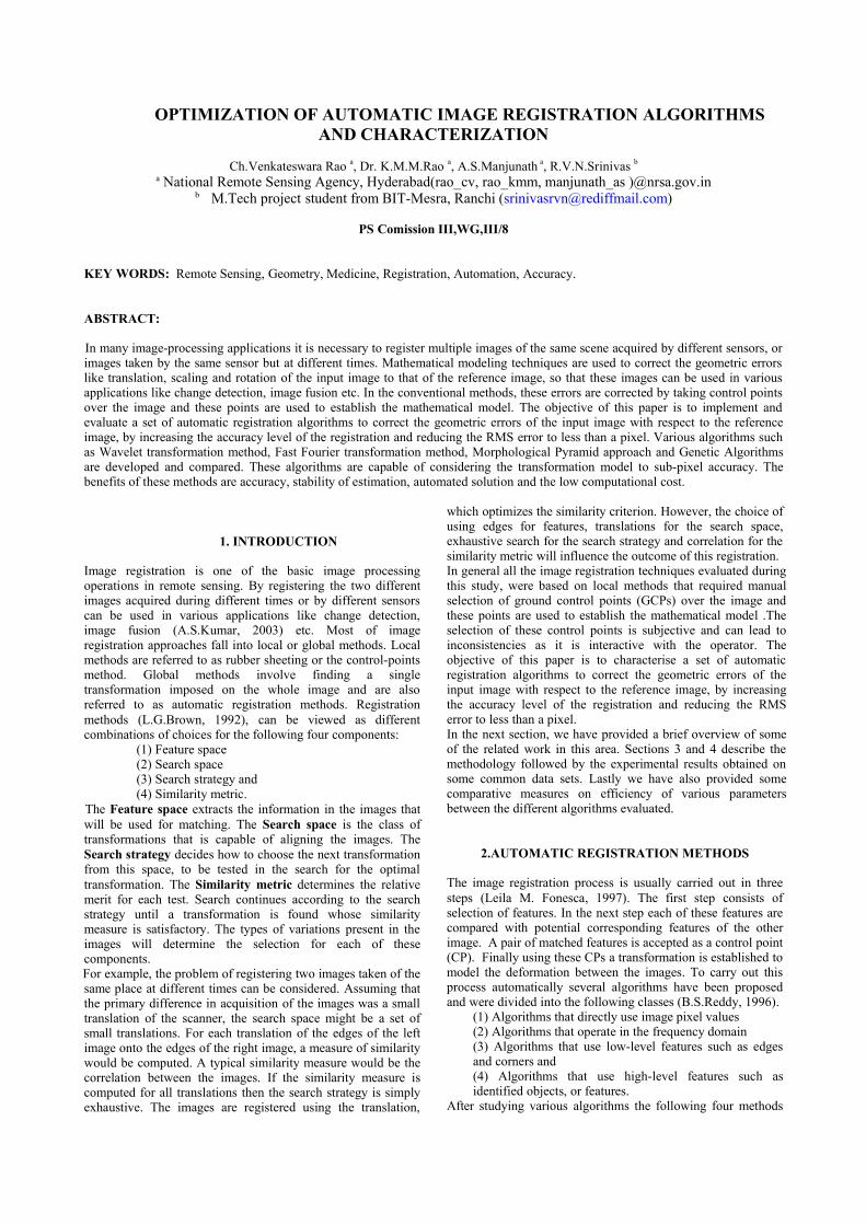
transform. A point from the input image is taken and itscorrelations with all the points from the reference image arecalculated. Then, the point with which it has the maximumcorrelation is its most similar feature point. A constant α=2.5 isused to control the number of feature points selected for thematching in the modulus maxima. In order to select the mostsignificant feature points α is also in the higher levels. ACorrelation threshold Tc = 0.85 is defined to limit the numberof matched control point pairs. If the achieved correlation isgreater than this threshold, then both the points are matched.The area of matching window wc = 7, the size of refinementmatching window wr = 3 is chosen for finding the correlation.We have taken care of the well distribution of the control pointsthrough out the image by splitting the image into 5X5 grids andin each grid minimum of one control point is selected. Theactual consistency check(H. Li, 1995) is done in an iterativefashion through which the most likely incorrect match isidentified recursively in each step. If RMSE is too large,another round of consistency check is carried out. The iterationcontinues until acceptable RMSE is achieved. This first part ofthe matching process is the crucial phase of the registrationprocess. The algorithm is progressive at higher levels ofwavelet sub bands to improve the registration accuracy. TheRMSE at the finer level is achieved as 0.45 pixels. Fig 3 showsthe warped image.
4.2 FAST FOURIER TRANSOFROM APPROACH
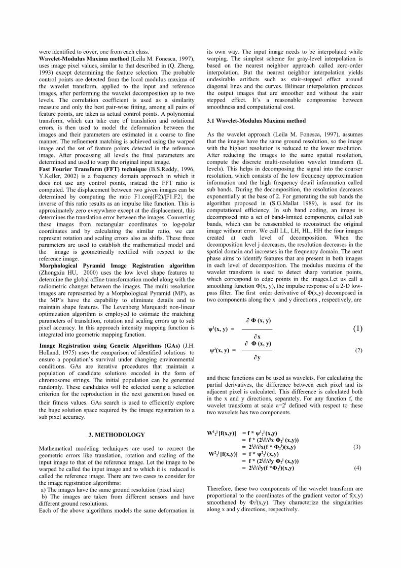
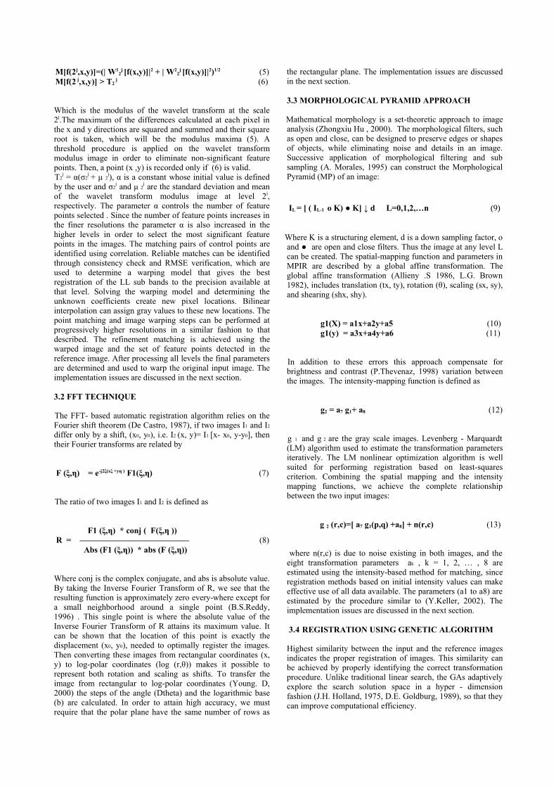
Rotation and Scale can be represented as shifts in the log –polar coordinates. From this log – polar images (Young.D,2000) by using phase correlation and Fourier shift theoremrotation and scale is derived. But while computing the log –polar image from the original rectangular coordinates leads topoints that are not located exactly at points in the original grid.This demands the interpolation. In this implementation bilinearinterpolation is adopted. An image is simulated for knownerrors of translation and rotation. The simulated image is shownin Figure 4. The corresponding log – polar image is shown inFigure 5. To implement this algorithm IDL/ENVI(HongjieXie, 2003) is being used. The FFT of the log – polar images ofboth input and reference images are created. By using theInverse FFT of the phase correlation ratio, the maximum
Figure 3 Warped Imge using Wavelet Modulus Maxima
absolute value and location indicates the rotation and scale. Anew image constructed by applying the rotation and scale and itis created by using bilinear interpolation. Once again by findingthe phase correlation ratio of the newly generated image withthe reference image, shift between the images are identified.The maximum absolute value of the Inverse FFT of this ratioprovides the shifts in both x and y directions. After deriving all
Figure 4 Simulated Image to be warped using FFT
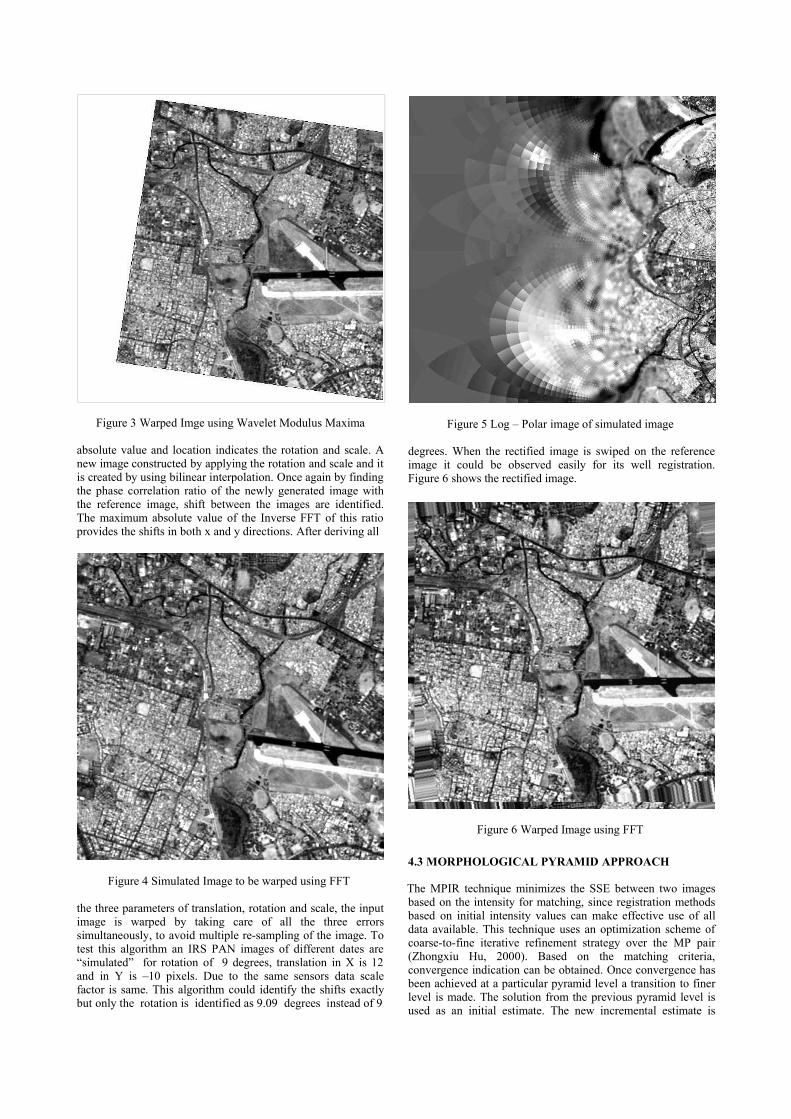
the three parameters of translation, rotation and scale, the inputimage is warped by taking care of all the three errorssimultaneously, to avoid multiple re-sampling of the image. Totest this algorithm an IRS PAN images of different dates are“simulated” for rotation of 9 degrees, translation in X is 12and in Y is –10 pixels. Due to the same sensors data scalefactor is same. This algorithm could identify the shifts exactlybut only the rotation is identified as 9.09 degrees instead of 9
Figure 5 Log – Polar image of simulated image
degrees. When the rectified image is swiped on the referenceimage it could be observed easily for its well registration.Figure 6 shows the rectified image.
Figure 6 Warped Image using FFT
4.3 MORPHOLOGICAL PYRAMID APPROACH
The MPIR technique minimizes the SSE between two imagesbased on the intensity for matching, since registration methodsbased on initial intensity values can make effective use of alldata available. This technique uses an optimization scheme ofcoarse-to-fine iterative refinement strategy over the MP pair(Zhongxiu Hu, 2000). Based on the matching criteria,convergence indication can be obtained. Once convergence hasbeen achieved at a particular pyramid level a transition to finerlevel is made. The solution from the previous pyramid level isused as an initial estimate. The new incremental estimate is
computed by minimizing the SSE between the re-sampledimages g1 and image g2.. This whole process is iterated at eachpyramid level to achieve the final estimation. Gray scale MPsare created using 3X3 structuring element and then sub-sampling the filtered image with d = 2. The initial estimatedparameters are identified arbitrarily. Using Levenberg –Marquardt algorithm by verifying the matching criteria theparameters a0 to a7 are iteratively identified in each of thepyramid levels.
4.4 REGISTRATUION USING GENETICS APPROACH
Randomly initialize the population, sufficiently large to berepresentative of the search as a whole. Each chromosome is oflength 32 bits(Prachya, 1999) allocates 12bits for rotation, 10bits for translation in x-direction and 10 more bits fortranslation in y-direction. Each field is a signed magnitudebinary number. A precision factor is used to improve theaccuracy. Evaluate the fitness function for each solution in thepopulation to see if the termination criteria for optimality aremet. In our case study correlation is used as fitness function.Used a weighted roulette wheel sampling to reproduce stringsof the next generation in proportion to their fitness. Evaluatethe fitness of each new individual. Thus we obtain a solutionstring or chromosome, which is used to transform the imageusing affine transformation and bilinear interpolation.Population size and number of generations were limited to 150,regstration accuracy observed as less than a pixel.
5. CONCLUSIONS
Wavelet Modulus Maxima appraoch assumes the images are ofsame resolution. In this method threshold parameters need to beinteractively provided. Due to pyramidal approach it allows forfaster implementation and higher registering precision. It ismore adequate to register images taken from the same sensor.It worked well for images taken at different times, which aretypical to remote sensing applications. Since this uses thecontrol points approach it can rectify the local errors, whichemulates manual registration of images. FFT techniqueprovides accuracy acceptably good. The algorithm works forimages in which the scale change is less than 1.8 (Hongjie Xie,2003). Due to the global transform this approach cannotdetermine local geometric distortions. The MPIR algorithmwith an intensity-based differential matching technique isreliable and efficient. This algorithm capable of measuring theerrors, to sub pixel accuracy, the displacement between imagessubjected to affine transformation, which includes simultaneoustranslation, rotation, scaling, and shearing. GAs can efficientlysearch the solution space and gives the solution to achieve thesub pixel accuracy without identifying the control points.Through global transformation a model can be established fortranslation and rotation errors. The proposed algorithm expectsboth the images are of same scale. Computational efficiencycan be improved by adopting the pyramidal approach.Depending on the type of variations in the medical images ofComputerized Tomography, PET or MRI images some of thesetechniques can be adopted for making the various observations.It is unlikely that a single registration scheme will worksatisfactorily. To characterize these algorithms the commondata sets from IRS PAN are used and there is no scale variation.
ACKNOWLEDGEMENTS
The authors would like to thank Dr. R. R. Naval gund, DirectorNRSA for encouraging us to carry out this work at NRSA.
REFFERENCES
Alliney, S., Anij Morandi, C. 1986, Digital image registrationusing projections IEEE Trans. PAMI-8, 2 (Mar.), 222-233.
A. Morales, T. Acharya, and S. Ko, “Morphological pyramidswith alternating sequential filters”, IEEE Trans. ImageProcessing, vol.4, pp. 965-977, 1995.
A.S.Kumar, A.S.Manjunath and K.M.M. Rao , “ Merging IRS-Multispectral and PAN images by A-Trous wavelets”. Int.Journal of Remote Sensing , 2003 (communicated).
B.S.Reddy and B.N.Chatterji, “An FFT-based technique fortranslation, rotation and scale invariant image registration”,IEEE Transactions on Image Processing, 5(8): 1266 –1271,1996.
De Castro E, and Morandi C, 1987. Registration of translatedand rotated images using finite Fourier Transforms, IEEETrans. PAMI-9, 5 (Sept.),700-703.
D. E. Goldburg, Genetic Algorithms in Search: optimizationand machine learning, Reading, Mass. Addison-Wesley,1989.
H. Li, B. S. Manjunath, and S. K. Mitra, “A contour-basedapproach to multisensor image registration,” IEEE Trans.ImageProcessing, vol.4, pp. 320-334, 1995.
Hongjie Xie,NigelHicks,G.randy Keller Haitao Huang ,”AnIDL/ENVI implementation of the FFT-based algorithm forautomatic image registration” .Int.Jl of Computers andGeosciences, vol .29 ,pp 1045-1055, 2003.
J. H. Holland, “Adaptation in Natural and Artificial System,”University of Michigan Press, Ann Arbor, 1975.
Leila M.Fonesca and Max H.M.Costa,”Automatic Regestrationof Satellite Images”,Proceedings on IEEE transaction ofcomputer society,1997,pp 219-226.
Prachya Chalermwat, Tarek A. El-Chazawi “Multi resolutionimage registration using Genetics, ICIP(2) 1999:452-456.
P. Thevenaz, U.E. Ruttimann, and M. Unser, “A pyramidapproach to sub pixel registration based on intensity,” IEEETrans. Image Processing, vol.7, pp. 27-41, 1998.
Q.Zheng and R.A.Chellappa. “Computational vision approachto image registraion”. IEEE Transactions on Image Processing,2(3) : 311-326, July 1993.
S.G. Mallat “A theory for multi-resolution signaldecomposition: the wavelet representation.” IEEE Trans. OnPattern Anal. And Machine Intell. , 11(7):674-693, July 1989.
YOUNG.D “Straight lines and circles in the log-polar image”.Proceedings of the British Machine Vision Conference 2000,BMVC, 2000, Bristol, UK, 11-14 September 2000, pp 426-435
Zhongxiu Hu and Scott T.Acton,”Morphological PyramidImage Registration” 4th IEEE south west symposium 2000.P227.