Page 1
2016 Science in the Age of Experience 1 http://www.3ds.com/events/science-in-the-age-of-experience
Optimization of Heavy-Duty Cylinder Head Gasket Manufacturing Press Using Isight
Jason M. Tyrus, Rohit Ramkumar, Kevin Shaver
Power Technologies Group, Dana Holding Corporation, Lisle, IL, USA
Kevin Harris
Dassault Systemes, SIMULIA, Johnston, RI, USA
Abstract: The production of heavy-duty cylinder head gaskets requires processing large sheet
materials in a relatively short amount of time. In many cases, there is a need to quickly heat the
materials to a consistent and uniform temperature. This high-volume process contrasts with a
typical heated-press molding operation where the time required for each press cycle is much
longer, on the scale of multiple minutes rather than seconds. Raw material weight of several
kilograms and a required temperature increase of more than one-hundred degrees Celsius cause
the power supply and control requirements to be very complex. Modification of platen designs and
development of a new process require unique simulation techniques to optimize the process and
equipment.
In this paper, Isight and Abaqus are used to simulate and improve the multiple-stage
manufacturing process of heavy-duty cylinder head gaskets. An iterative procedure using Abaqus
with custom scripting is first used to identify the required power input to achieve steady-state
press operation. An Isight process flow is then developed to simulate the manufacturing process of
coils of material being fed into continuous process equipment and automatically bonded in a
heated platen press simulated by Abaqus. Isight parameter studies are then applied to examine the
heater power required to maintain a consistent temperature on the platens to minimize both heat
loss and press stabilization time. The combination of Abaqus and Isight is used to improve both
the heavy-duty gasket manufacturing process performance and the resulting product
quality.
Keywords: Design Optimization, Heat Transfer, Optimization, Output Database, Postprocessing,
Powertrain, Seal, Parameter Study, Manufacturing, Composites
Page 2
2 2016 Science in the Age of Experience http://www.3ds.com/events/science-in-the-age-of-experience
1. Introduction
Many processes involved in the manufacture of automotive components require the input of heat
in a controlled manner. Some examples include the cure of a coating, injection molding of plastic
components, and adhesive cross-linking. These processes almost always involve several different
variables which will affect both the speed of the process and the quality of the finished product. It
is imperative to design the process and equipment in such a way that both the time involved and
the part quality will meet the required criteria. One such automotive component in which the
process and equipment design play a crucial role is the manufacture of heavy-duty cylinder head
gaskets for use on diesel engines.
Today’s diesel engines produce high engine firing pressures and elevated temperatures. These
demands can place stress on the cylinder-head gasket. In the gasket design process, it is necessary
to choose a material that matches the application requirements. Materials used to make heavy-duty
cylinder head gaskets must be relatively thick, strong, and conformable. It is common to combine
several different types of materials, such as steel and graphite, into one multi-layer composite in
order to meet these requirements. Victocor® cylinder-head gaskets use a patented material capable
of withstanding these high cylinder pressures and elevated temperatures where other gaskets fail.
1.1 Victocor® Cylinder-Head Gasket Design
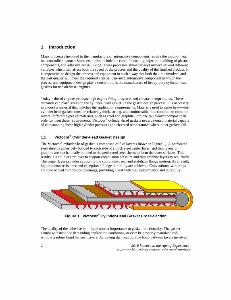
The Victocor®
cylinder-head gasket is composed of five layers (shown in Figure 1). A perforated
steel sheet is adhesively bonded to each side of a thick steel center layer, and thin layers of
graphite are mechanically bonded to the perforated steel sheets to form the outer surfaces. This
results in a solid center layer to support combustion pressure and thin graphite layers to seal fluids.
The center layer provides support to the combustion seal and stabilizes flange motion. As a result,
high blowout resistance and exceptional flange durability are achieved. Conventional wire rings
are used to seal combustion openings, providing a seal with high performance and durability.
Figure 1. Victocor® Cylinder-Head Gasket Cross-Section
The quality of the adhesive bond is of utmost importance to gasket functionality. The gasket
cannot withstand the demanding application conditions, or even be properly manufactured,
without a robust bond between layers. Achieving the most durable bond between layers involves
Page 3
2016 Science in the Age of Experience 3 http://www.3ds.com/events/science-in-the-age-of-experience
the use of time, temperature, and pressure to effectively cross-link the adhesive. Once these
parameters are determined, it must be verified that the manufacturing equipment is capable of
providing these conditions in a repeatable and reliable fashion.
2. Manufacturing Process
Heavy-duty cylinder head gaskets are considered large in size with dimensions exceeding 1 meter
in length and 0.3 meters in width. The proportions of the gasket require the use of heated presses
with correspondingly high surface area to induce the heat transfer under predefined conditions of
time, temperature, and pressure. A high volume gasket manufacturer may produce more than
1,000,000 of these gaskets per year. The competitive business environment and practical
production limitations require a fast process, on the order of seconds rather than minutes or hours.
To process the large sheet materials in a relatively short amount of time, a multi-stage
manufacturing process is utilized. The process consists of coils of material being fed into
continuous process equipment and automatically bonded in a heated platen press. Process speed
requirements dictate that an enormous amount of energy be quickly transferred between the press
platen and the gasket material. The gasket material temperature must be increased several hundred
degrees Celsius and maintain a precise set point until the cross-linking is sufficient. The variation
of the temperature must be kept as low as possible to minimize any deviations in product quality
within sheets.
Figure 2. Heated Platen Press.
The design of the heated platens is an ambitious project. Even though there is a wide knowledge
base for guidelines involving heated presses, they almost exclusively apply to slower, low-
Page 4
4 2016 Science in the Age of Experience http://www.3ds.com/events/science-in-the-age-of-experience
powered production where fast response and uniformity are of less concern. There are complicated
interactions between material and press equipment which are more significant in a fast process.
These interactions have severe effects on the resulting process capabilities. The large platens are
an expensive item to procure, making upfront design work and simulation critical to the success of
the proposed production line. Isight is used to determine the power requirements for the heater
cartridges of such a platen system while avoiding potentially costly mistakes.
3. Simulation Approach
The main goal of the analysis is to determine the minimum power output required by the heater
cartridges in order to maintain a nearly uniform set point temperature at the platen surface. The
heater cartridges are then sized appropriately for the press. Thermocouples in the lamination
platens of the press measure the temperature at set sensor points to ensure a uniform surface
temperature. To solve the problem, an iterative procedure using Abaqus is first used to identify the
initial power input required to achieve a uniform steady-state temperature on the lamination
platens of the press prior to operation. This initial analysis utilizes Abaqus/Standard with custom
scripting. The inputs are adjusted for correlation to temperature readouts from the press
thermocouples at steady-state operation. Next, an Isight process flow simulates the manufacturing
process of coils of material being fed into and automatically bonded in a heated platen press
simulated by Abaqus. Using the steady-state temperature map obtained as an initial condition on
the press, Isight parameter studies are applied to examine the heater power required to maintain a
consistent temperature on the platens in order to minimize both heat loss and press stabilization
time during continuous operation. To achieve the objective, the heater cartridge power that will
balance a shorter warmup time with a reasonable surface temperature distribution must be
determined. If the heater power is too low, the time required to stabilize the system may exceed
1000 seconds, which is not considered acceptable. If the heater cartridge power is too high, the
control algorithms will not be able to sustain a low deviation from the set point across the entire
platen surface.
3.1 Press Initial Condition Analysis
The first step in the analysis is to calibrate the heated platen press model (shown in Figure 3) to
achieve the desired target temperature during steady-state operation. Abaqus/Standard is used to
apply surface flux to the heater cartridge locations (shown in Figure 4) in order to achieve the
steady-state operation temperature recorded from thermocouple data on the actual press without
the gasket in the model. There is no feedback loop modeled in this stage of the analysis; rather, the
heat flux is continuously applied until steady-state is reached. The manufacturing process
simulation begins once good temperature correlation is achieved.
Page 5
2016 Science in the Age of Experience 5 http://www.3ds.com/events/science-in-the-age-of-experience
Figure 3. Heated Platen Press Model.
3.2 3-Stage Process with Abaqus and Custom Scripting
The temperature map from the baseline analysis is used as input to the 3-stage heavy-duty cylinder
head gasket manufacturing process. The first stage is the material feed, during which the press is
open and there is material contact with the bottom lamination platen only. The graphite and steel
core are set to the initial condition during this material feed step. The next stage in the process is
the press closure. During this step, there is material contact with the top and bottom lamination
platens and there is heat transfer across the components. There are two meshed model input files
that are changed in the control deck through the use of a control deck included file specification to
simulate either an open press or a closed press. The third stage in the process loop consists of the
press opening during which the press opens and there is again material contact with the bottom
lamination platen only. Throughout all steps of the 3-stage analysis, it is necessary to use a
feedback loop. The feedback loop is employed through the use of the Abaqus subroutine UAMP
to apply heat flux based on nodal temperatures. There are twelve heater cartridges in the press
which are controlled by thermocouple sensors (shown in Figure 4). Each thermocouple sensor
controls two heater cartridges.
Page 6
6 2016 Science in the Age of Experience http://www.3ds.com/events/science-in-the-age-of-experience
Figure 4. Heater Cartridge and Sensor Node Locations.
The feedback from the sensor nodes using the subroutine UAMP along with custom scripting
either turns each pair of heater cartridges off or on separately. Each heater’s status depends on the
comparison of the temperature at each sensor node to a defined set point temperature. The heaters
are turned off or on as needed to maintain a uniform temperature on each platen based on the
deviation of each sensor reading from the set point after each time increment. Turning a heater off
or on is done by setting the amplitude of the flux applied to that heater to 0 or 1 through the use of
the subroutine. Using the temperature map obtained from the initial baseline run as the initial
condition on the press, heat transfer analysis is run continuously for 1540 seconds, which amounts
to 110 gasket sheets. The temperature on the gasket is reset to the initial condition for each new
sheet to simulate new material sheets entering the press. The press temperature is not reset for
each new gasket sheet; rather, the temperature condition on the press from the last increment in the
preceding step becomes the initial condition of each successive step, thereby simulating
continuous operation of the press over time. The input files are generated through the use of a
Python submission script and the temperature initial condition in the input file for each successive
stage in the process is set through the use of the same Python script. This looping procedure must
be repeated each time a new power level is desired to be tested. After the simulation is run, there is
also the task of extracting the results and plotting the data. This tedious method of running the
model is an ideal candidate for automation.
3.3 3-Stage Process with Isight Implementation
Isight is used to fully automate the heat press heat transfer analysis process (shown in Figure 5)
and applied to determine the best heater cartridge power setting to be used by the heat press for
manufacturing a given number of gaskets.
Page 7
2016 Science in the Age of Experience 7 http://www.3ds.com/events/science-in-the-age-of-experience
Figure 5. Isight Workflow.
The root of the process, the level with which users are to primarily interact, is configured with the
primary input and output parameters needed to drive the process to determine the best power
setting. The root level input parameters are:
• Heater_Cartridge_Power: the heater cartridge power setting in Watts. This parameter is
defined by the user, but is also the primary parameter that is automatically iterated upon using
a Design of Experiments (DOE) method.
• Number_Gasket_Sheets: the number of gasket sheets to run through the heat press at a given
heater cartridge power setting during the manufacturing process.
• Set_Point: the desired temperature where all 12 sensors stabilize as the manufacturing process
progresses. The best heater cartridge power setting is the one at which all sensor temperatures
stabilize in the shortest amount of cumulative time of the simulated manufacturing process.
• Job_Name: the Abaqus job name and the name used throughout the process to represent and
name the associated content created, such as the runtime directory, output files, etc.
The root level output parameters defined to expose measures that quantify the heat press analysis
process results per a given heat press power setting are the following:
• SetPoint_Aggregate_CT: the sum of the cumulative time (CT) for each sensor to reach the
setpoint temperature after the first initial temperature drop. This parameter assumes that a
heater cartridge power setting that achieves the lowest value of this parameter, compared to
the others, would be preferred as this represents the heat press achieving an overall steady
state in a shorter amount of time than the others.
• Min_Temp_Over_All_Sensors: the minimum temperature observed over all sensors
throughout the heat press analysis process.
• Sensor_Slowest_to_Reach_Setpoint: the sensor number that has the slowest cumulative time
to reach the desired set point temperature.
Page 8
8 2016 Science in the Age of Experience http://www.3ds.com/events/science-in-the-age-of-experience
The root level is set to a Design of Experiments component configured to perform a parameter
study. This parameter study is configured to modify a single factor, Heater_Cartridge_Power.
This factor is set at 6 power setting levels: 1500, 2000, 2500, 3000, 3500, and 4000 Watts. This
configuration defines an entire multi-gasket heat press analysis process for each
Heater_Cartridge_Power factor setting. The flexibility of the Isight Design of Experiments
component allows the study to evolve in the future as it can be easily expanded and modified to
include more parameters at different configurations with different Design of Experiments
methods. This can also be easily modified to change from a Design of Experiments method to an
Optimization method as desired in the future.
The subflow of the Isight process is the portion of the process that automatically executes all the
steps and manages all of the data (both parametric and files) required to complete the simulated
heat press manufacturing process for a given number of gasket sheets for each heater cartridge
power setting. The steps within the subflow consist of:
• A Calculator component, using the Heater_Cartridge_Power parameter within a formula to
create the surface flux used on each of the 12 heater cartridges.
• An Operating System (OS) command component, configured with a windows batch file using
SSH copy and execution commands, to stage the remote HPC runtime directory that is used
throughout the power setting process pass. This staging includes:
o The creation of a uniquely named HPC runtime directory
o The transfer of the initial condition Abaqus output database (ODB) file to the HPC
runtime directory. This file is referenced to apply the initial temperature of the first
Abaqus solve.
o The transfer of three included files to the HPC runtime directory, which are needed
for each of the 3 Abaqus solves per gasket sheet.
• A Loop component (configuration shown in Figure 6) to iterate over the value of the
Number_Gasket_Sheets parameter. By setting up a parameter for the number of gasket sheets
to be solved, the number of iterations is controlled easily from the root components
parameters.
Page 9
2016 Science in the Age of Experience 9 http://www.3ds.com/events/science-in-the-age-of-experience
Figure 6. Isight Looping Component.
Within the subflow of the loop component, there are three simulation code components, each
configured to create the unique input deck and perform the distributed Abaqus execution for the
following stages of each gasket loop pass:
• Abaqus solve 1: material feed
• Abaqus solve 2: press closure
• Abaqus solve 3: press opening
Each of these simulation code components has an input file parse used to create a unique input
deck and a windows batch file, changed during runtime, to perform the respective distributed
Abaqus execution on a Linux HPC.
The input file parse does two important file parsing actions to the respective Abaqus input deck
template to generate a unique input deck:
1) Write the Abaqus output database (ODB) file from the previous Abaqus solve as the
current solve’s initial temperature reference. If this happens to be the very first
Abaqus solve, then the staged initial condition ODB file created from the heated
platen press steady-state calibration analysis is used.
2) Replace the value of surface flux (from the calculation) to each of 12 DSFLUX
commands within the respective Abaqus input deck template.
Page 10
10 2016 Science in the Age of Experience http://www.3ds.com/events/science-in-the-age-of-experience
Once the input deck is parsed and created, the OS command portion of the respective simulation
code component, configured with a windows batch script, is executed to copy the newly created
input deck to the HPC runtime working directory. The file is provided as the argument to Abaqus
within the distributed working directory.
After the loop is complete, having executed the three Abaqus solves per gasket, an OS command
is used to execute a Python script in the runtime directory of the remote HPC to extract the
temperature data for each sensor node and place it in a single ASCII file. This single file is parsed
with a data exchange component and places the values of the 12 sensor temperatures per
cumulative time in Isight resizable arrays. These arrays are passed to a final calculation
component configured to create the root level output parameters (SetPoint_Aggregate_CT,
Min_Temp_Over_All_Sensors, and Sensor_Slowest_to_Reach_Setpoint) for each
Heater_Cartridge_Power factor setting as defined within the root level Design of Experiments
parameter study.
4. Results
Since the heaters are all off at the start of the simulation due to the press being heated to steady-
state prior to operation, the temperature immediately drops below the set point as cold material
sheets begin to enter the press in operation, thereby causing the heater cartridges to turn on. There
is some lag observed for the heat transfer to reach the sensor nodes once the application of heat
flux begins after the sensor nodes fall below the set point since the heater cartridge surfaces and
sensor nodes are not at the same location. No sensors have stabilized about the set point in 1540
seconds at the 1500 W power setting (shown in Figure 7), while all sensors have stabilized about
the set point after 1140 seconds at the 2500 W power setting except sensors 7 and 12 (shown in
Figure 8). These two sensors are located at the outside ends of the bottom platen, and are losing
the most heat in operation to the outside of the press and the cold gasket sheets entering the press.
All sensors have returned to the set point in less than 1000 seconds using the 3500 W power
setting for the heater cartridges (shown in Figure 9). Sensor 7 is the slowest sensor to stabilize
about the set point at the power settings of interest. Only the 3500 W and 4000 W settings allow
sensor 7 to return to the set point in less than 1000 seconds (shown in Figure 10).
Page 11
2016 Science in the Age of Experience 11 http://www.3ds.com/events/science-in-the-age-of-experience
Figure 7. Sensor Temperature Versus Time For All Sensors at 1500W Power.
Figure 8. Sensor Temperature Versus Time For All Sensors at 2500W Power.
Page 12
12 2016 Science in the Age of Experience http://www.3ds.com/events/science-in-the-age-of-experience
Figure 9. Sensor Temperature Versus Time For All Sensors at 3500W Power.
Figure 10. Sensor 7 Temperature Versus Time.
Page 13
2016 Science in the Age of Experience 13 http://www.3ds.com/events/science-in-the-age-of-experience
The results of the parameter study are summarized in Table 1. Heater cartridge power less than
3000 W is not sufficient to allow all sensors to return to the set point before 1540 seconds has
elapsed. A power setting of 3000 W results in 1190 seconds elapsing before all sensors return to
the set point; however, it is desired that less than 1000 seconds elapse before all sensors return to
the set point to reduce the scrap rate. Therefore, we see that the minimum heater cartridge power
required in order to return all sensors back to the defined set point in less than 1000 seconds while
keeping the scrap rate below the desired limit is 3500 W.
Table 1. Results
Heater Cartridge Power (W)
Time for All Sensors to Return to Set Point
(s)
Number of Scrap Sheets Before Set Point is Reached
Sensor Slowest to Reach Set Point
1500 > 1540 > 110 1 2000 > 1540 > 110 1 2500 > 1540 > 110 7 3000 1190 85 7 3500 829 60 7 4000 659 48 7
5. Conclusions
The Isight results demonstrate that a cartridge power of 3500 W achieves the desired balance of
less than 1000 seconds for system stabilization and minimal surface temperature variation. The
uniform surface temperatures improve the quality of the bond in difficult areas near platen edges,
eliminating layer delamination and corresponding gasket leakage, thereby creating a more robust
gasket. Additionally, the scrap rate experienced in production decreases since the problematic
warm up period is reduced. With a working Isight model in place, future work of modifying the
lamination platens and the heater platens will be undertaken.